Design of Rate-Compatible Parallel Concatenated Punctured Polar Codes for IR-HARQ Transmission Schemes


Communication Engineering Research Centre, Harbin Institute of Technology (Shenzhen), Shenzhen 518055, China
*
Authors to whom correspondence should be addressed.
†
These authors contributed equally to this work.
Entropy 2017, 19(11), 628; https://doi.org/10.3390/e19110628
Submission received: 16 August 2017
/
Revised: 2 November 2017
/
Accepted: 20 November 2017
/
Published: 21 November 2017
(This article belongs to the Section Information Theory, Probability and Statistics)
Abstract
:In this paper, we propose a rate-compatible (RC) parallel concatenated punctured polar (PCPP) codes for incremental redundancy hybrid automatic repeat request (IR-HARQ) transmission schemes, which can transmit multiple data blocks over a time-varying channel. The PCPP coding scheme can provide RC polar coding blocks in order to adapt to channel variations. First, we investigate an improved random puncturing (IRP) pattern for the PCPP coding scheme due to the code-rate and block length limitations of conventional polar codes. The proposed IRP algorithm only select puncturing bits from the frozen bits set and keep the information bits unchanged during puncturing, which can improve 0.2–1 dB decoding performance more than the existing random puncturing (RP) algorithm. Then, we develop a RC IR-HARQ transmission scheme based on PCPP codes. By analyzing the overhead of the previous successful decoded PCPP coding block in our IR-HARQ scheme, the optimal initial code-rate can be determined for each new PCPP coding block over time-varying channels. Simulation results show that the average number of transmissions is about 1.8 times for each PCPP coding block in our RC IR-HARQ scheme with a 2-level PCPP encoding construction, which can reduce half of the average number of transmissions than the existing RC polar coding schemes.
1. Introduction
Polar codes, proposed by Arikan [1], are the first class of structured channel codes that can provably achieve the capacity of the binary-input discrete memoryless symmetric channels via a low-complexity successive cancellation (SC) decoder [2,3,4,5,6]. The encoding and decoding complexity of polar codes are log, where N is the block length [7,8]. Furthermore, in [9,10], Ido Tal and Niu Kai have independently derived a successive cancellation list (SCL) decoding algorithm, which can achieve maximum likelihood decoding performance with decoding complexity log, where L is the size of the list. In addition, by adding a few extra bits of cyclic redundancy check (CRC) to the transmitted bits, polar codes with an SCL decoding algorithm are comparable with state-of-the-art low-parity parity check (LDPC) codes and Turbo codes [11]. Because of their good performance and low complexity, polar codes have been selected for use in the upcoming fifth-generation (5G) communication systems [12,13,14,15].
In general wireless communication scenarios in future 5G systems, flexible and adaptive transmission techniques are required due to the time-varying nature of wireless channels [16,17,18]. One approach is to have several pairs of different code-rate encoders and decoders to adapt to the channel variations [19]. However, this requires extra coding complexity.
As an alternative, a popular solution to compensate for channel state variations is incremental redundancy hybrid automatic repeat request (IR-HARQ) [20,21,22], where the parity bits are sent in an incremental fashion depending on the quality of the time-varying channel. In this way, the rate-compatible (RC) codes are well-suited for the IR-HARQ scheme to address the scalable code-rate requirement, which can be implemented with a single encoder/decoder pair. Therefore, if decoding is not successful at a particular rate, then the receiver can request only the additional parity bits from the transmitter, instead of the full set of parity bits of the code with a lower rate.
Although polar codes can achieve the capacity of any binary memoryless symmetric channel, which is natural to be applied to IR-HARQ transmission schemes [23], their RC constructions are not in general capacity-achieving due to the limitation of the block length of conventional polar codes being restricted to a power of two.
In general, a family of RC polar codes typically obtained by puncturing, where the set of parity bits of a code with a higher rate is a subset of the set of parity bits of a code with a lower rate. The study of puncturing patterns for polar codes to obtain arbitrary block lengths and code-rates are considered in [24,25,26,27]. However, puncturing of polar codes incurs a loss of performance, and the performance of these punctured codes are worse than the conventional polar codes even if they have the same length and code rate. Authors in [28] proposed an efficient polar coding scheme for optimizing jointly the puncturing patterns and the set of information bits of the polar code, and showed that it outperformed the LDPC codes defined in WiMAX standard. Moreover, the puncturing patterns in [25,26,27,28] are optimized according to the set of information bits, these methods cannot be used to design a family of RC punctured codes for IR-HARQ, which requires the same information set that should be used for all punctured codes from a mother code in the family. Consider the heuristic search algorithm presented in [24], which developed a good puncturing pattern for a fixed information set. Therefore, in order to determine an optimal RC puncturing patterns, one needs to consider the trade-offs between complexity and reliability [29,30,31], which is still an open problem.
Recently, Refs. [32,33] have proposed RC polar-like codes that are provably capacity-achieving over any class of a degraded family of channels. Both solutions take advantage of the nested property of polar codes for degraded channels, where the transmitter keeps sending additional code bits of a mother code to the receiver until a decoding succuss is announced. Then, the receiver can decode the whole block through a sequential decoding procedure. However, due to the block length and code-rate limitation of polar codes, both constructions of RC polar codes can achieve the capacity only for a sequence of rates that satisfy a certain relationship. Furthermore, these RC coding schemes can be used only when the family of channels over which the transmission takes place is ordered by degradation; otherwise, the nested property does not hold.
Therefore, we develop an IR-HARQ transmission scheme based on a family of RC polar codes named parallel concatenated punctured polar (PCPP) codes in this paper. The PCPP coding scheme are optimized for a sequence of successively degraded channels and used for our IR-HARQ transmission scheme, for which the main ideas are exploited from concatenated polar coding construction that can be decoded by a sequence of parallel polar decoders [33]. The main contribution and novelty of this paper can be summarized as follows:
- We investigate an improved random puncturing (IRP) pattern for the PCPP coding scheme to obtain a sequence of nested encoding functions in a PCPP coding block transmission, for which the set of parity bits of a higher code-rate polar code is a subset of the set of parity bits of a lower code-rate polar code for a PCPP coding block IR-HARQ transmission. The proposed IRP algorithm only selects puncturing bits from the frozen bits set and keeps the information bits unchanged during puncturing, which can achieve 0.2–1 dB decoding performance improvement more than the existing random puncturing (RP) algorithm.
- To realize multiple blocks transmission over a time-varying channel, we develop an RC IR-HARQ transmission scheme based on PCPP codes, where Refs. [32,33] were only optimized in a single block transmission case. By analyzing the overhead of the previous successful decoded PCPP coding block in our IR-HARQ scheme, the optimal initial code-rate can be determined for each new PCPP coding block over time-varying channels. Simulation results show that the average number of transmissions is about 1.8 times for each PCPP coding block in our RC IR-HARQ scheme with a 2-level PCPP encoding construction, which reduces half of the average number of transmissions than the existing RC polar coding schemes.
The remainder of this paper is organized as follows. In Section 2, we present some preliminaries of polar codes and rate-compatibility. In Section 3, we introduce our IRP algorithm that limits the selection of puncturing patterns on the set of frozen bits. Then, we propose our RC PCPP coding scheme for IR-HARQ transmission in Section 4. In Section 5, the optimal initial code-rate is analyzed for multiple RC PCPP coding blocks for IR-HARQ schemes over time-varying channels. The simulation results and comparisons for the proposed scheme and existing schemes are presented in Section 6. Finally, Section 7 concludes the paper with some remarks and suggestions of further research work.
2. Preliminaries
2.1. Polar Codes
Polar codes are proposed based on the phenomenon of channel polarization: N polarized sub-channels () can be obtained by channel combining and splitting operation on N independent discrete memoryless channels (DMCs). In this work, the most reliable K sub-channels will be selected by a Density Evolution (DE) algorithm [29] to transmit information sets and the rest of the sub-channels will be used to transmit frozen sets, where K is the number of information bits.
Polar codes can be uniquely determined by three parameters , where is the block length, is the code-rate and K-element subset , where and . We refer to this set as the information set, and the complementary set is referred to as the frozen set. Let denote an information vector of size . The K information bits are placed in those elements of corresponding to the set , and frozen bits (deterministic values, typically zeros) are placed in corresponding to the complementary set . The codeword corresponding to an information vector to be transmitted is then generated by
where is the generator matrix, is an permutation matrix that acts as a bit-reversal operator, is a kernel of the polarizing transformation and is the n-th Kronecker power of .
2.2. Successive-Cancellation (SC) Decoding
Arikan proposed a Successive cancellation (SC) decoding algorithm for polar codes [1], the SC decoder generates the estimate of i-th bit based on the previous estimates of and the channel output , and we denote that for . The transition probabilities are used to define the N binary-input coordinate channels , which is denoted as follows:
where and denote the output and input of , respectively. and denote the input and transition probabilities of synthesized channel after the channel combining phase [1]. Then, the log likelihood ratio (LLR) for the i-th bit is calculated by
where is defined as
Accordingly, each LLR can be calculated as follows:
where and denote the sub-vectors consisting of elements of with odd and even indices, and ⊕ denotes modulo-2 addition. According to the initial values, .
In addition, the belief propagation (BP) decoding algorithm for polar codes is also proposed in [1], which can outperform the SC algorithm with higher complexity , where t is the number of BP decoding iterations.
The most effective polar decoding algorithm is the successive-cancellation list (SCL) decoding algorithm, which is proposed in [9,10] as an upgrade version of the SC algorithm. SCL can be regarded as a joint optimization method of the SC algorithm and the maximum likelihood (ML) algorithm [34]. In the SCL decoding process, source bit is not decoded immediately at each step, instead of finding a maximum of l candidate paths. For each source bit , the SCL algorithm doubles the number of decoding paths by pursuing both and options, and then preserves the most likely l paths in a list and discards others. When all the source bits are traversed, the most reliable path is chosen as the output of the decoder. The complexity of SCL decoding is log.
The simple successive cancellation (SSC) [35] is proposed to decrease the decoding complexity of the SC algorithm. The successive cancellation stack (SCS) [36] is proposed to reduce the complexity of SCL in some conditions. The SCL decoding can combine with cyclic redundancy check (CRC) in a concatenated coding fashion to further improve the performance of polar codes [11], which substantially outperformed the state-of-art turbo and LDCP codes.
2.3. Rate-Compatible Polar Codes
Let denote a family of J channels. If their respective capacity is , we call that a sequence of successively degraded channels [37] and it is referred as . A family of rate-compatible (RC) polar codes can be designed for such degraded channels where their respective information sets are such that , which is called nested property. Each polar code for has the same block length N and with code-rates and each .
Li, B. et al. [32] and Hong, S.-N. et al. [33] proposed two RC polar-like coding schemes. In both schemes, the sender first transmits the code block with a predetermined maximum rate . If the decoding is successful at the receiver, this block is successfully transmitted and the procedure ends; otherwise, an error message (NACK) is fed back to the sender, and the received data is stored in the buffer and waits for decoding with further transmission data blocks. In the second transmission, the code block with rate will be transmitted. The second code block is constructed by the information bits that were put on the indices in the first transmission, and these information bits are now put on the indices , and rest are frozen bits. Here, represents the relative complement of in .
The transmission will be stopped until the k-th code block is decoded successfully, where and the information bits are those with the indices in all of the previous transmissions, and the length of the frozen bits is .
After the k-th code block is decoded successfully, then the receiver can decode the previous buffered code block in a backward decoding strategy according to the nested property. The decoded bits will be used as frozen bits to help decode the -th polar code block . Then, the code-rate of the -th code block is reduced to . Therefore, the -th code block can be decoded. Likewise, all the previous buffed code blocks can be decoded backwards after times decoding and all the information bits are recovered.
Though these schemes can provide a simple way to construct a family of RC codes with the degraded rates , we find it is unable to achieve arbitrary rates in [32], and the puncturing scheme in [25] caused serious performance loss, and the information bits may be punctured and the nested property does not hold. Moreover, both of the schemes lack introduction of how to measure the reliabilities of the subchannels without any channel information in the first transmission. Thus, we need to address these problems in our new scheme in this paper.
3. Improved Random Puncturing Algorithm Polar Codes
To break the limitation of the block length of the polar codes, which is restricted to a power of two in practical communication systems, an effective way is puncturing. Let denote the puncturing pattern, and indicate that the i-th coded bit will be punctured. Ref. [31] has investigated the impact of puncturing on a given information set, and proved that the overall system performance depends on the performance of both the punctured and the unpunctured (mother) code, which are further constrained by a joint optimization of both and .
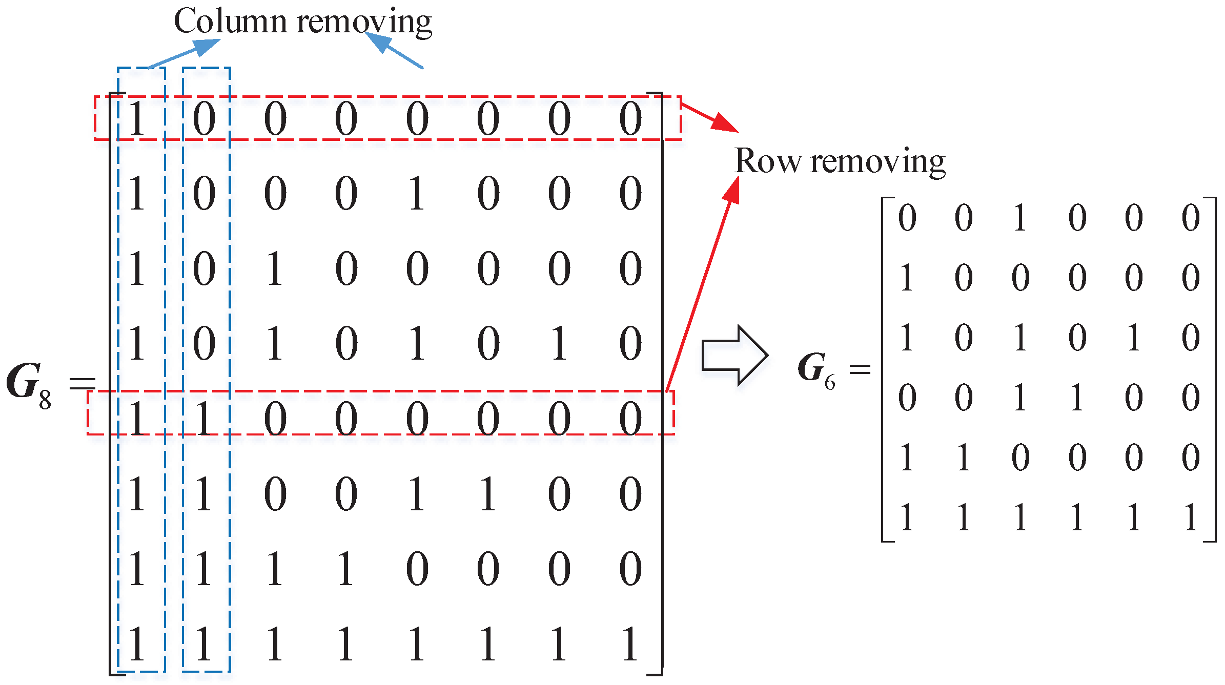
Let and denote the block length and code-rate of the mother polar code, and denote the block length and code-rate of the punctured polar code, respectively. A punctured polar code with block length can be obtained by puncturing bits from a mother code with block length , which is equivalent to moving columns and rows from generation matrix . In order to ensure that the puncturing matrix is reversible [26], the indices of the moved columns vectors i are the same as the puncturing positions, and the indices of the puncturing rows vector are , where is the bit-reversal function. Figure 1 shows how to construct a polarizing matrix when . If the puncturing codewords are and , then the 1st, the 2nd column and the 1st and the 5th row should be moved from generation matrix .
Recall the encoding process in Equation (1), it can be rewritten as
where denotes the frozen part of source block , is the sub-matrix of formed by the row with indices in , and is defined in the same fashion.
We can identify from Equation (6) that the random puncturing algorithms allow the chance to puncture some important information bits, which will lead to a block error [38], and the simulation result will be shown in Section 6. On the other hand, the same information set should be used for all punctured codes in a family of RC codes.
Consider the equivalent puncturing positions , if i is the position of puncturing information bits, then the rows to be moved are , which is equivalent to the columns to be moved are . Therefore, we can limit the puncturing positions in the set [38], and propose an improved random puncturing (IRP) algorithm.
Let a mother polar code with block length and the code-rate be , and the punctured code is with block length . The IRP algorithm is briefly described as follows:
Stage 1: Initialize the values in a puncturing pattern and set as all ones;
Stage 2: The encoder randomly selects bits in the frozen bits set for puncturing, and the corresponding indices in are flipped to zeros.
4. System Model
Base on a family of the above RC punctured polar codes, we can construct our parallel concatenated punctured polar (PCPP) codes over any sequence of successively degraded channels to transmit K information bits. Their information sets are nested and the block length and the corresponding code-rate for each PCPP coding block are satisfied
where is equal to the number of the information bits in the PCPP codes. In addition, for each block length , we can use our IRP algorithm to construct a sequence of nested punctured polar codes with rates , and the length of the information bits in each punctured code block is the same to satisfy
The RC PCPP coding scheme for IR-HARQ transmission is described as follows. In the first transmission, the sender transmits the code block while carrying all the K information bits. If the first transmission fails, the received data will be stored and the second code block will be transmitted. The information bits located at the indices of the first block should be put at the current information set and encoded, where is the information set that consists of the most reliable indices when the block length is . If the second transmission also fails, the third block will be constructed by the information bits located at the indices of the first block and the information bits located at indices of the second block. Continuously, the transmission will be stopped if the decoding succeeds after the k-th block is transmitted or . Then, we could decode the previous blocks backward to recover all of the K information bits as well as the decoding of the RC polar codes in Section 2.3.
In the following, we will give a more detailed explanation of the main idea through a 3-level RC PCPP coding scheme as shown in Figure 2. In this case, a information set of 12 bits will be transmitted through three transmissions and a 3-level PCPP code block is needed to encode where with the parameters , , , . We start by constructing the PCPP coding block for the 1st transmission, as shown in Figure 2a, where are the information bits. When the 1st transmission fails, the 2nd PCPP coding block will be sent, where can be calculated according to Equation (7), and the information bits are by calculating .
Assuming the 2nd transmission also fails in this example, the sender performs the 3rd transmission with , for which the block length is not satisfy power of two and can not be obtained by polar encoder directly. Then, we use the IRP algorithm to construct the 3rd PCPP coding block. In addition, to avoid the block error caused by puncturing too many bits, we should do our best to minimize the number of puncturing bits. Hence, we choose a mother polar code with block length , and the number of information bits in the 3rd transmission can be calculated as ; then, the code-rate of the mother code is . The 3rd polar code has been punctured eight bits from the mother code, and the information bits in are . Then, the sender finishes all three transmissions of the 3-level RC PCPP coding blocks.
As shown in Figure 2b, the backward decoding process begins when the 3rd PCPP coding block can be decoded successfully.
Step 1: the receiver starts by decoding the 3rd PCPP coding block and recovers the information bits , which can be used to decode the other two previously received PCPP coding blocks that were stored in the buffer.
Step 2: according to the nested property, the decoded bits are regarded as frozen bits in , and the 2nd PCPP coding block turn to a coding block, where the rate 2nd PCPP coding block is reduced to . Then, the remaining information bits can be decoded successfully.
Step 3: the information bits in the two previously decoded PCPP coding block are regarded as frozen bits in , to decode the remaining information bits with the code-rate also being reduced to . Therefore, all of the 12 information bits have been decoded through the 2 times backward decoding.
According to the above analysis, it is worth noting that, although the RC PCPP coding scheme can achieve arbitrary rates and block lengths, the coding complexity needs to be optimized. First, assume that K information bits are transmitted successfully after k time transmissions and the sender has been transmitting k-level PCPP coding blocks; then, there are k pairs of encoders and decoders that are needed to construct the k-level PCPP codes, which lead to a complex system structure. The key to addressing this problem is by considering the continuous block transmission over time-varying channels, where the last successive transmission of the PCPP coding blocks can help the sender to determine the optimization coding parameters for the next data block encoding in the first transmission. We will discuss this optimization RC IR-HARQ transmission scheme in detail in the following.
5. Rate-Compatible IR-HARQ Transmission Scheme Based on PCPP Codes
In this section, we design a RC IR-HARQ transmission scheme based on PCPP codes, to transmit multiple data blocks continuously over a time-varying channel. In our RC IR-HARQ transmission scheme, a channel capacity estimation is fed back to the sender after each PCPP coding block is successfully transmitted. Then, an optimal initial code-rate is determined by the sender for the next transmission. The optimization method for determining the coding parameters of each 1st PCPP coding block is as follows.
5.1. Initial Code-Rate and Number of Transmissions of the RC IR-HARQ Scheme
A general method of constructing RC IR-HARQ transmission scheme for transmitting multiple data blocks over a time-varying channel is described as follows. Assuming the first data block is encoded by the PCPP coding scheme with the initial code-rate (the rate of ), after k transmissions the receiver can be decoded successfully and the final rate is . Then, a simple analysis of the number of transmissions corresponding to the different initial code-rates for the second data block is shown in Table 1.
Obviously, in a continuous data block transmission over a time-varying channels scenario, is closer to the real channel capacity than , which leads to a simpler structure of PCPP codes as well as less transmissions. Therefore, the key to simplifying the RC IR-HARQ scheme is to choose an optimal initial code-rate that is close to the time-varying channel capacity . However, the exact is unavailable for the sender in a practical wireless system.
Let denote a capacity interval after the n-th data block is transmitted successfully and , where is the final code-rate of the PCPP coding block and is the code-rate of the last PCPP coding block that cannot be decoded. Then, the initial code-rate of for the -th data block can be chosen according to for the time-varying channel. Similarly, we can get such interval after the transmission of each data block and choose an optimal rate according to the interval for the next data block. The detail of the optimization method for determining the initial code-rate for the 1st PCPP coding block of RC IR-HARQ transmission scheme is given in the next subsection.
5.2. Optimization Method for the 1st PCPP Coding Block of the RC IR-HARQ Transmission Scheme
As analyzed above, an estimation interval of the channel capacity can be obtained after each data block is transmitted successfully in our RC IR-HARQ transmission scheme. Here, let denote the capacity interval after the 1st block is transmitted successfully and . Then, the initial code-rate of for the 2nd data block can be chosen according to . Furthermore, let denote the capacity interval after the n-th data block is transmitted successfully, and denote the corresponding channel capacity and . In a practical time-varying wireless system, the estimation error of the real channel state information is hard to eliminate. However, our optimization method for the 1st PCPP coding block of RC IR-HARQ transmission scheme can work well, and we will discuss the affection of the estimation error in the following.
First, let denote the variation range of the time-varying channel capacity that can be obtained from the statistical information of the time-varying channel; denotes the difference of the code-rates between any two adjacent PCPP coding blocks; is the k-th PCPP coding block in the n-th block transmission, where the receiver begins the backward decoding with the k-th received PCPP coding block; is a sequence of nested punctured polar codes, where is the j-th puncturing pattern and the mother code is .
Recall the variation range of the time-varying channel capacity . Then, our optimization method for choosing the initial code-rate of the -th data block from the capacity interval can be distinguished into three possible cases, which are illustrated in Figure 3.
Case 1: the minimum channel capacity satisfies and the maximum channel capacity satisfies as shown in Figure 3a. Then, the optimal initial code-rate for the -th block is .
If the time-varying channel capacity increases, and the channel capacity satisfies , since the maximum channel capacity is , and the initial code-rate is , which is beyond the channel capacity as , then the rate of the 2nd PCPP coding block is . Hence, a 2-level PCPP code for the -th block can be constructed with rates and , and two time transmissions can ensure the data block delivery, and we have at the end of this data block transmission. In particular, if , the -the data block with the initial code-rate PCPP coding block can be transmitted successfully in one time transmission.
Else, if the time-varying channel capacity decreases, the channel capacity satisfies , and the initial code-rate is . Similarly, we then need to construct the 2nd PCPP coding block with rate , and this can be decoded by receiver. Therefore, a 2-level PCPP codes for the -th data block is needed to construct with rates and , and the final state is .
Case 2: if the minimum channel capacity satisfies and the maximum channel capacity satisfies as shown in Figure 3b, then, the optimal initial code-rate for the -th block is .
If the time-varying channel capacity increases, and the channel capacity satisfies with the maximum channel capacity satisfying , similar to the previous case, a 2-level PCPP code for the -th data block needs to be constructed with rates and to successfully deliver the data block in two time transmissions with for the next data block transmission. In addition, if and the initial code-rate for the -th data block is , the data block can be delivered in one time transmission.
Else, if the channel capacity decreases, we can distinguish two subcases: if the channel capacity satisfies , the construction of the -th data block is the same as in Case 1, which is a 2-level PCPP code with rates and ; if the channel condition goes through a severe deterioration as , the initial code-rate and 2nd code-rate are higher than the channel capacity, until the 3rd PCPP coding block with the code-rate is transmitted, and the receiver can begin the backward decoding. Therefore, a 3-level PCPP codes for the -th data block needs to be constructed, and is fed back to the sender.
Case 3: if the minimum channel capacity satisfies and the maximum channel capacity satisfies as shown in Figure 3c, then the optimal initial code-rate for the -th block is , which is obtained by puncturing a mother code .
In this case, when the channel capacity increases, the channel capacity can increase to . If we choose as the initial code-rate for the -th block, the -th data block can be transmitted successfully in one time transmission. However, if we do so, we will have , which is decreasing the efficiency of the channel use. Therefore, the sender in Case 3 needs to construct a punctured polar code with initial code-rate from the mother code with code-rate .
If the channel capacity increases, we can distinguish three subcases: If , the -th data block with the initial code-rate PCPP coding block can be transmitted successfully in one time transmission, and the feedback channel capacity interval is . Else, if , a 2-level PCPP code with rates and can transmit the -th data block successfully in two time transmissions with for the next data block transmission. In addition, puncturing does not need extra encoders and decoders, and the transmission in this subcase only needs one pair of encoder and decoder. Last, if , then a 3-level PCPP codes for the -th data block needs to be constructed with code-rate , and , respectively. Furthermore, the data delivery is finished in three time transmissions with two pairs of encoders and decoders.
Else, if the channel capacity decreases, similarly, two subcases can be distinguished: if the channel capacity satisfies , the -th data block with a initial code-rate 2-level PCPP codes can be transmitted successfully in two time transmissions as well as the above subcase in Case 3. Else, if , then the sender needs to construct 3-level PCPP codes for the -th data block transmission, with code-rate , and , respectively. Furthermore, the final state feedback to the sender is .
In summary, in our RC IR-HARQ transmission scheme, the main idea to determine an optimal initial code-rate for the PCPP coding block is according to the capacity interval feedback from the last successful data block transmission. If the initial code-rate lower than , the PCPP coding block can be transmitted successfully in one time transmission, but it will be suboptimal if the channel capacity increases in the next several data blocks transmission. If we choose an initial code-rate larger than , then the number of transmission may be larger than 2. As analyzed above, in most situations, a 1-/2-level PCPP coding construction can reliably transmit the data blocks by using our optimal initial code-rate method over a time-varying channel.
5.3. Parameter Optimization
a. Rate difference and the variation range of the time-varying channel
In Section 5.2, we analyzed the optimal initial code-rate for the PCPP coding block in our RC IR-HARQ transmission scheme over a time-varying channel in three different cases, where the key parameters of our design method are dependent on the rate difference and the variation range of the time-varying channel . The complete characterization of the optimal initial code-rate with these two parameters in Section 5.2 are given in Table 2.
b. Number of punctured bits
Recall the Case 3 in Section 5.2, where we need to construct a punctured polar code with initial code-rate from the mother code with code-rate to transmit the -th data block. Let be a sequence of nested punctured polar codes, where is the -th puncturing pattern. Let denote the number of punctured bits and meet the conditions that and .
Our IRP algorithm has limited the puncturing pattern to avoid selecting from the information bits set, such that we have and the number of punctured bits is calculated as
6. Simulation and Comparison
6.1. Performance of the Improved Random Puncturing Algorithm
In this subsection, we present Monte Carlo simulation results to evaluate the performance of our IRP algorithm over a binary-input additive white Gaussian noise (BI-AWGN) channel with antipodal signaling , and other system parameters are provided in Table 3.
The bit error rate (BER) and frame error rate (FER) performance of our IRP algorithm, the random puncturing (RP) algorithm [25], the stop-tree puncturing (STP) algorithm [25], and the reliability-Type I algorithm [38] are shown in Figure 4. Obviously, we can observe that by avoiding information bit punctured, the IRP algorithm significantly outperforms the other three algorithms, and the STP algorithm provides the worst BER and FER performance due to the requirement of a BP decoding algorithm instead of the SCL decoding algorithm [8].
When the punctured polar code-rate is , the performance of punctured codes under IRP algorithm obtains a 0.2 dB gain at BER and 0.2 dB at FER more than the RP algorithm. With the increasing of the punctured polar code-rate, the advantages of our proposed IRP algorithm increases. When the punctured polar code-rate is , the IRP algorithm outperforms the RP algorithm and obtains a 1 dB gain at BER and 0.3 dB at FER , respectively. Moreover, the RP algorithm suffers from an error-floor when the punctured polar code-rate is , where our IRP algorithm can completely avoid the problem.
6.2. Performance of the RC IR-HARQ Transmission Scheme
In this subsection, we simulate the performance of our RC IR-HARQ transmission scheme, the Monte Carlo simulation result of the average number of transmissions of data blocks with the PCPP coding scheme is present. The system parameters are the same as provided in Table 3, and the rest of the simulation parameters are shown in Table 4. The simulation result of the average number of transmissions is shown in Figure 5 and Figure 6, where the horizontal axis is the index of data blocks, and lines with the marker “○” denotes the results of our proposed scheme, while the marker “∗” represent the results of the RC polar-like (RCP) scheme in [33].
Figure 5 shows the average number of transmissions of our RC IR-HARQ scheme and the RCP scheme for a sequential of 100 data blocks transmission in 3 cases with the initial channel capacity . Our RC IR-HARQ scheme can reduce half of the average number of transmissions than the RCP scheme as shown in Figure 5a, and also significant less than the RCP scheme in Figure 5b,c. Because all the initial code-rates of the data blocks in the RCP scheme are equal to , the average number of transmissions for the sequential data blocks is substantially equal to the first data block, and the successful transmission of previous data block does not help enhance the efficiency of the next ones. Therefore, the average number of transmissions in the RCP scheme is about 2.8 times in Case 1 as shown in Figure 5a, and 3.5 times in Case 2 as shown in Figure 5b, and 2.7 times in Case 3 as shown in Figure 5c.
In contrast with the RCP scheme, our RC IR-HARQ scheme is more adaptable to the continuously data blocks transmission. The PCPP codes for the 1st data block are with the initial code-rate PCPP coding block; then, the optimal initial code-rate of the PCPP codes for the continuously data block transmission can be determined in different cases as discussed in Section 5.2. Therefore, after the 1st data block transmission, the average number of transmissions of our RC IR-HARQ scheme is rapidly decreased compared to the RCP scheme. The average number of transmissions in the RC IR-HARQ scheme is about 1.8 times in Case 1, as shown in Figure 5a, and 2.4 times in Case 2, as shown in Figure 5b, and 2.5 times in Case 3, as shown in Figure 5c, which is verified by our theoretical analysis, as shown in Table 2. It is worth noting that our RC IR-HARQ scheme has the best performance in Case 1, which means the accurate statistical information of the time-varying channel can help the PCPP encoding and decoding in the RC IR-HARQ transmission scheme, and it can help joint optimization with the channel estimation.
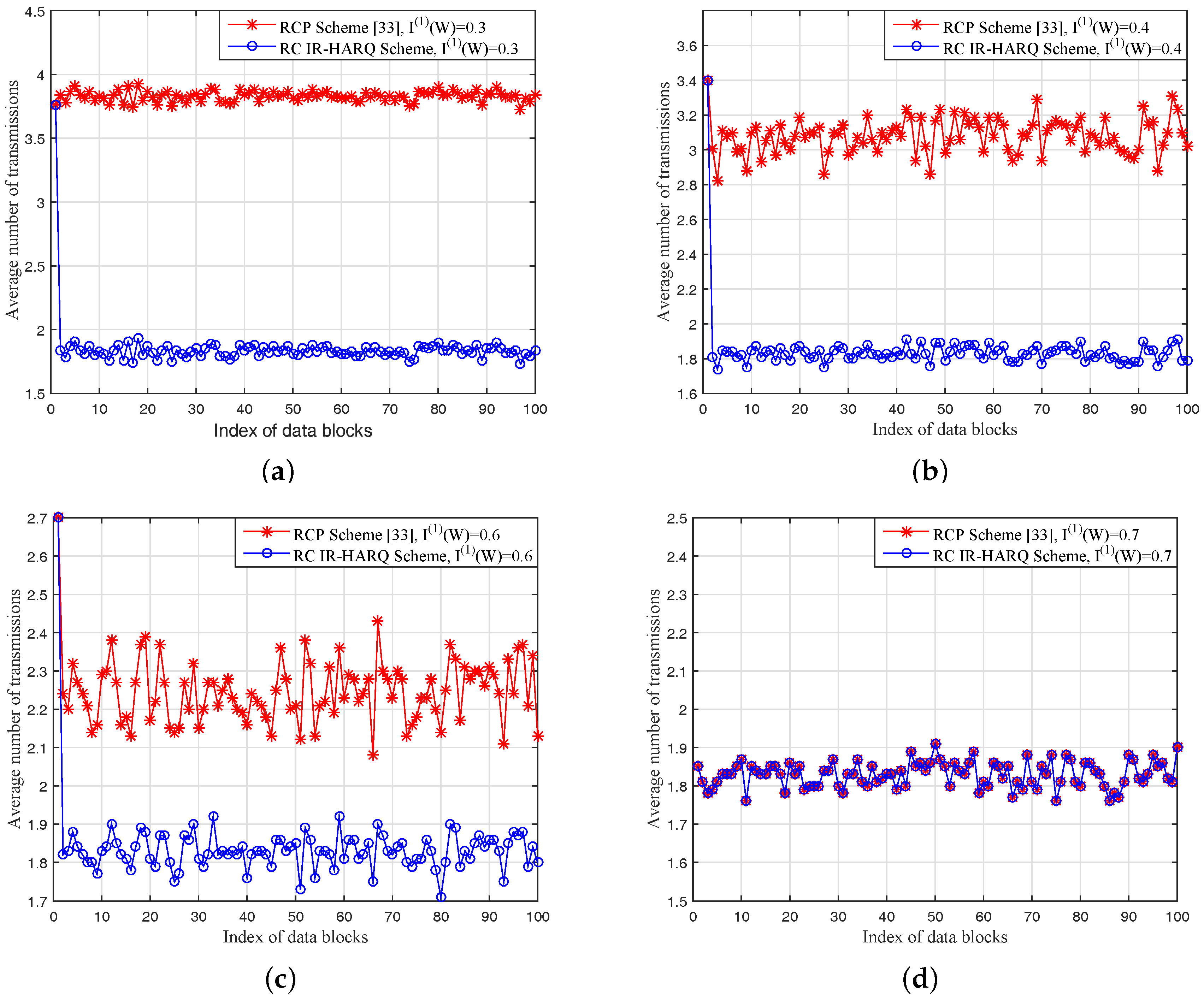
Moreover, we simulate the performance with different initial channel capacity in Case 1 as shown in Figure 6, where is 0.3, 0.4, 0.6, and 0.7, and other simulation parameters are the same as is given in Table 4. The average number of transmissions in the RCP scheme are 3.8 times, 3.1 times, 2.2 times, and 1.8 times in Figure 6a–d, respectively. Obviously, the average number of transmissions of the RCP scheme is strongly dependent on the difference between and the , as shown in Figure 6a–d.
It is worth noting that the average number of transmissions in both schemes is about 1.8 times when , as shown in Figure 6d. Because the initial code-rates in Case 1 is , and for both schemes, when , both schemes can finish the transmission in no more than two time transmissions.
In our RC IR-HARQ scheme, the average number of transmission in Figure 6 are all about 1.8 times under different , which proves that our scheme can perform well over the time-varying channel if the sender has statistical information on the channel. Furthermore, as the average number of transmissions is less than the RCP scheme, the encoder and decoder pairs are also less in the sender and receiver, which is important in practical wireless communication systems.
7. Conclusions
In this paper, we proposed a RC IR-HARQ transmission scheme based on PCPP codes to support data transmission over a time-varying channel. First, we designed an improved random puncturing algorithm that limited the puncturing patterns in the frozen bits of polar codes, which can provide RC polar codes for practical wireless communication systems, and gain about 0.2–1 dB decoding performance better than the existing puncturing schemes. Then, considering the continuous block transmission over a time-varying channels scenario, by utilizing analyzing the overhead of the previous successful decoded PCPP coding block in our RC IR-HARQ scheme, the optimal initial code-rate can be determined for each new PCPP coding block over time-varying channels. Simulation results show that the average number of transmissions is about 1.8 times for each PCPP coding block in our RC IR-HARQ scheme with a 2-level PCPP encoding construction, if the sender has the accurate statistical information of the time-varying channel. Our proposed scheme is independent of channel state and can be flexible over the time-varying channel. Furthermore, if the statistical information of the channel is not accurate, the PCPP codes can achieve joint optimization with a channel estimation algorithm for future work.
Acknowledgments
This work was supported in part by the National Natural Sciences Foundation of China (NSFC) under Grants 61771158, 61701136, 61525103 and 61371102, the Natural Scientific Research Innovation Foundation in Harbin Institute of Technology under Grant HIT. NSRIF. 2017051, and the Shenzhen Fundamental Research Project under Grant JCYJ20160328163327348 and JCYJ20150930150304185.
Author Contributions
Jian Jiao and Sha Wang put forward the main idea and designed the RC IR-HARQ transmission scheme. Jian Jiao, Sha Wang and Bowen Feng performed the analysis and prepared the manuscript. All authors participated in writing the manuscript. All authors read and approved the final manuscript.
Conflicts of Interest
The authors declare no conflict of interest.
References
- Arikan, E. Channel polarization: A method for constructing capacity-achieving codes for symmetric binary-input memoryless channels. IEEE Trans. Inf. Theory 2009, 55, 3051–3073. [Google Scholar] [CrossRef] [Green Version]
- Mori, R.; Tanaka, T. Performance and construction of polar codes on symmetric binary-input memoryless channels. In Proceedings of the IEEE International Symposium on Information Theory(ISIT), Seoul, Korea, 28 June–3 July 2009. [Google Scholar]
- Vangala, H.; Viterbo, E.; Hong, Y. A comparative study of polar code constructions for the awgn channel. arXiv 2015, arXiv:1501.02473. [Google Scholar]
- Li, H.; Yuan, J. A practical construction method for polar codes in awgn channels. In Proceedings of the IEEE Tencon Spring Conference (TSC), Sydney, Australia, 17–19 April 2013. [Google Scholar]
- Mondelli, M.; Hassani, S.; Maric, I.; Hui, D.; Hong, S. Capacity-achieving rate-compatible polar codes for general channels. In Proceedings of the IEEE Wireless Communications and Networking Conference Workshops (WCNCW), San Francisco, CA, USA, 19–22 March 2017. [Google Scholar]
- Arikan, E. A performance comparison of polar codes and reed-muller codes. IEEE Commun. Lett. 2008, 12, 447–449. [Google Scholar] [CrossRef] [Green Version]
- Mondelli, M.; Urbanke, R.; Hassani, S.H. Unified scaling of polar codes: Error exponent, scaling exponent, moderate deviations, and error floors. In Proceedings of the IEEE International Symposium on Information Theory (ISIT), Hong Kong, China, 14–19 June 2015. [Google Scholar]
- Hussami, N.; Korada, S.B.; Urbanke, R. Performance of polar codes for channel and source coding. In Proceedings of the IEEE International Symposium on Information Theory (ISIT), Seoul, Korea, 28 June–3 July 2009; pp. 1488–1492. [Google Scholar]
- Tal, I.; Vardy, A. List decoding of polar codes. In Proceedings of the IEEE International Symposium on Information Theory (ISIT), St. Petersburg, Russia, 31 July–5 August 2011. [Google Scholar]
- Chen, K.; Niu, K.; Lin, J.R. List successive cancellation decoding of polar codes. Electron. Lett. 2012, 48, 500–501. [Google Scholar] [CrossRef]
- Niu, K.; Chen, K. CRC-aided decoding of polar codes. IEEE Commun. Lett. 2012, 16, 1668–1671. [Google Scholar] [CrossRef]
- Saber, H.; Marsland, I. An incremental redundancy hybrid ARQ scheme via puncturing and extending of polar codes. IEEE Trans. Commun. 2015, 63, 3964–3973. [Google Scholar] [CrossRef]
- Kim, H. Coding and modulation techniques for high spectral efficiency transmission in 5G and satcom. In Proceedings of the 23rd European Signal Processing Conference (EUSIPCO), Nice, France, 31 August–4 September 2015; pp. 2746–2750. [Google Scholar]
- Pandey, M.K.; Gaurav, A.; Kumar, V. Social, technical and economical challenges of 5G technology in indian prospective: Still 4G auction not over, but time to think about 5G in india. In Proceedings of the 2015 International Conference on Computer and Computational Sciences (ICCCS), Noida, India, 7–29 January 2015; pp. 157–162. [Google Scholar]
- Pirinen, P. A brief overview of 5g research activities. In Proceedings of the 1st International Conference on 5G for Ubiquitous Connectivity (5GU), Akaslompolo, Finland, 26–28 November 2014. [Google Scholar]
- Droste, H.; Rost, P.; Doll, M. An adaptive 5G multiservice and multitenant radio access network architecture. Trans. Emerg. Telecommun. Technol. 2016, 27, 1262–1270. [Google Scholar] [CrossRef]
- Posnakides, D.; Mavromoustakis, C.X.; Skourletopoulos, G. Performance analysis of a rate-adaptive bandwidth allocation scheme in 5G mobile networks. In Proceedings of the IEEE Symposium on Computers and Communication (ISCC), Larnaca, Cyprus, 6–9 July 2015. [Google Scholar]
- Simsek, M.; Zhang, D.; Öhmann, D. On the flexibility and autonomy of 5G wireless networks. IEEE Access 2017, 5, 22823–22835. [Google Scholar] [CrossRef]
- Babich, F.; Noschese, M.; Vatta, F. Analysis and design of rate compatible LDPC codes. In Proceedings of the International Symposium on Personal, Indoor, and Mobile Radio Communications (PIMRC), Valencia, Spain, 4–8 September 2016. [Google Scholar]
- Choi, J. On channel-aware secure HARQ-IR. IEEE Trans. Inf. Forens. Secur. 2017, 12, 351–362. [Google Scholar] [CrossRef]
- Khosravirad, S.R.; Pedersen, K.I.; Mudolo, L.; Bakowski, K. HARQ enriched feedback design for 5G technology. In Proceedings of the IEEE 84th Vehicular Technology Conference (VTC-Fall), Montreal, QC, Canada, 18–21 September 2016. [Google Scholar]
- Larsson, P.; Rasmussen, L.K.; Skoglund, M. Throughput analysis of Hybrid-ARQ—A matrix exponential distribution approach. IEEE Trans. Commun. 2016, 64, 416–428. [Google Scholar] [CrossRef]
- Mohammadi, M.; Collings, I.; Zhang, Q. Simple hybrid ARQ schemes based on systematic polar codes for IoT applications. IEEE Commun. Lett. 2017, 21, 975–978. [Google Scholar] [CrossRef]
- Zhang, L.; Zhang, Z.; Wang, X.; Yu, Q. On the puncturing patterns for punctured polar codes. In Proceedings of the IEEE International Symposium on Information Theory (ISIT), Honolulu, HI, USA, 29 June–4 July 2014; pp. 121–125. [Google Scholar]
- Eslami, A.; Pishro-Nik, H. A practical approach to polar codes. In Proceedings of the IEEE International Symposium on Information Theory Proceedings (ISIT), St. Petersburg, Russia, 31 July 2011. [Google Scholar]
- Shin, D.M.; Lim, S.-C.; Yang, K. Design of length-compatible polar codes based on the reduction of polarizing matrices. IEEE Trans. Commun. 2013, 61, 2593–2599. [Google Scholar] [CrossRef]
- Niu, K.; Chen, K.; Lin, J.R. Beyond turbo codes: Rate-compatible punctured polar codes. In Proceedings of the IEEE International Conference on Communications (ICC), Budapest, Hungary, 9–13 June 2013. [Google Scholar]
- Miloslavskaya, V. Shortened polar codes. IEEE Trans. Inf. Theory 2015, 61, 4852–4865. [Google Scholar] [CrossRef]
- Feng, B.; Jiao, J.; Wang, S.; Wu, S.; Zhang, Q. Construction of polar codes concatenated to space-time block coding in MIMO system. In Proceedings of the IEEE 84th Vehicular Technology Conference (VTC-Fall), Montreal, QC, Canada, 18–21 September 2016. [Google Scholar]
- Feng, B.; Zhang, Q.; Jiao, J. An efficient rateless scheme based on the extendibility of systematic polar codes. IEEE Access 2017, 5, 23223–23232. [Google Scholar] [CrossRef]
- Hong, S.-N.; Hui, D.; Marić, I. On the catastrophic puncturing patterns for finite-length polar codes. In Proceedings of the 50th Asilomar Conference on Signals, Systems and Computers (ACSSC), Pacific Grove, CA, USA, 6–9 November 2016. [Google Scholar]
- Li, B.; Tse, D.; Chen, K.; Shen, H. Capacity-achieving rateless polar codes. In Proceedings of the IEEE International Symposium on Information Theory (ISIT), Barcelona, Spain, 10–15 July 2016. [Google Scholar]
- Hong, S.-N.; Hui, D.; Mari, I. Capacity-achieving rate-compatible polar codes. In Proceedings of the IEEE International Symposium on Information Theory (ISIT), Barcelona, Spain, 10–15 July 2016. [Google Scholar]
- Niu, K.; Chen, K.; Lin, J.; Zhang, Q.T. Polar codes: Primary concepts and practical decoding algorithms. Commun. Mag. IEEE 2014, 52, 192–203. [Google Scholar] [CrossRef]
- Alamdar-Yazdi, A.; Kschischang, F.R. A simplified successive-cancellation decoder for polar codes. IEEE Commun. Lett. 2011, 15, 1378–1380. [Google Scholar] [CrossRef]
- Niu, K.; Chen, K. Stack decoding of polar codes. Electron. Lett. 2012, 48, 695–697. [Google Scholar] [CrossRef]
- Hassani, S.H.; Urbanke, R. Universal polar codes. In Proceedings of the IEEE International Symposium on Information Theory, Honolulu, HI, USA, 29 June–4 July 2014. [Google Scholar]
- Performance of Rate Matching Schemes for Polar Codes. R1-1712647, Prague, Czech Republic, 21–25 August 2017. Available online: http://portal.3gpp.org/ngppapp/TdocList.aspx (accessed on 28 August 2017).
Figure 1.
An example of puncturing from a generation matrix, where , and .

Figure 2.
The encoder and decoder structure of a 3-level PCPP code, where and : (a) encoder structure; (b) decoder structure.
Figure 2.
The encoder and decoder structure of a 3-level PCPP code, where and : (a) encoder structure; (b) decoder structure.
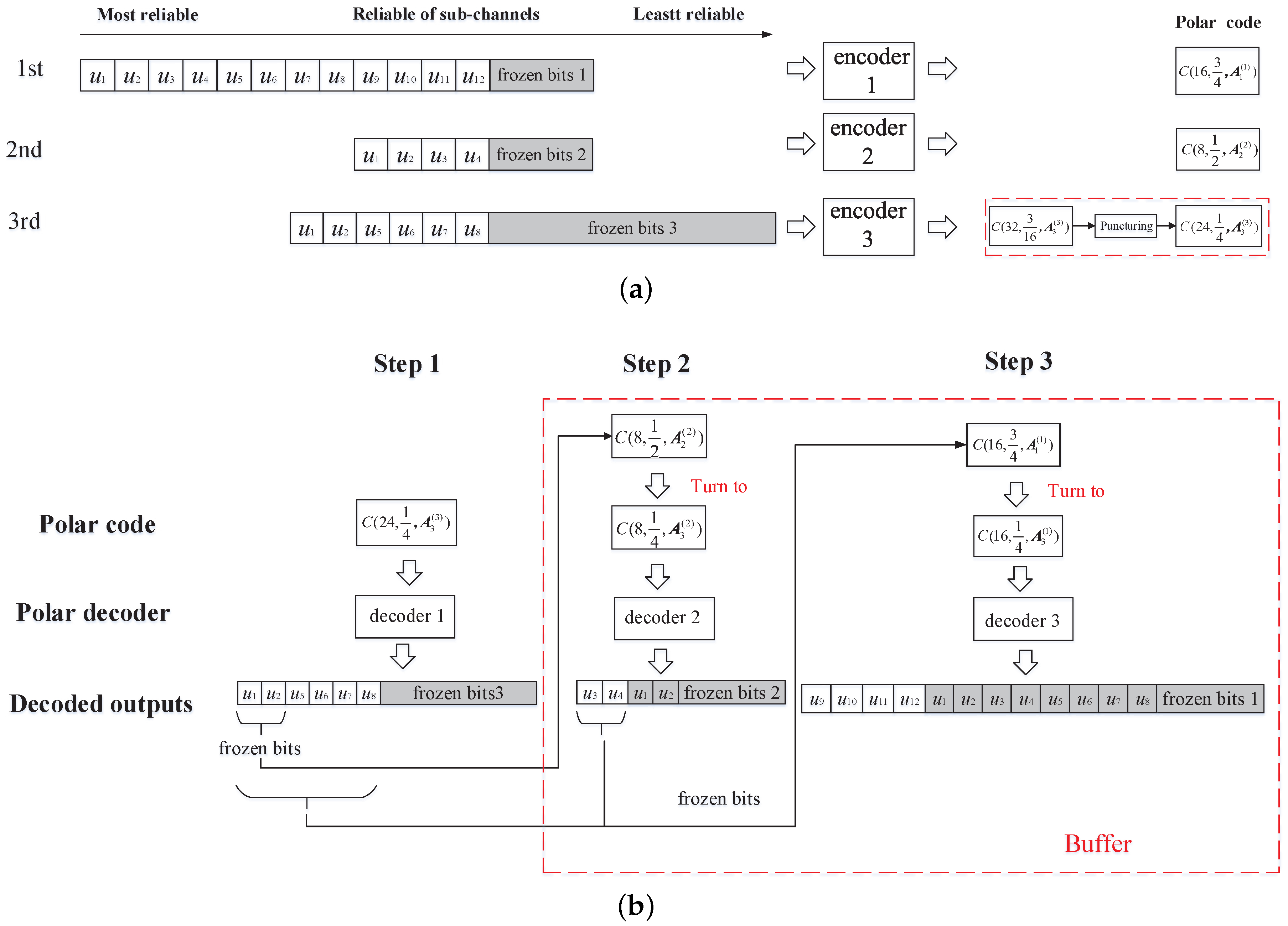
Figure 3.
Illustration of our optimization method in different cases: (a) ; (b) ; (c) .
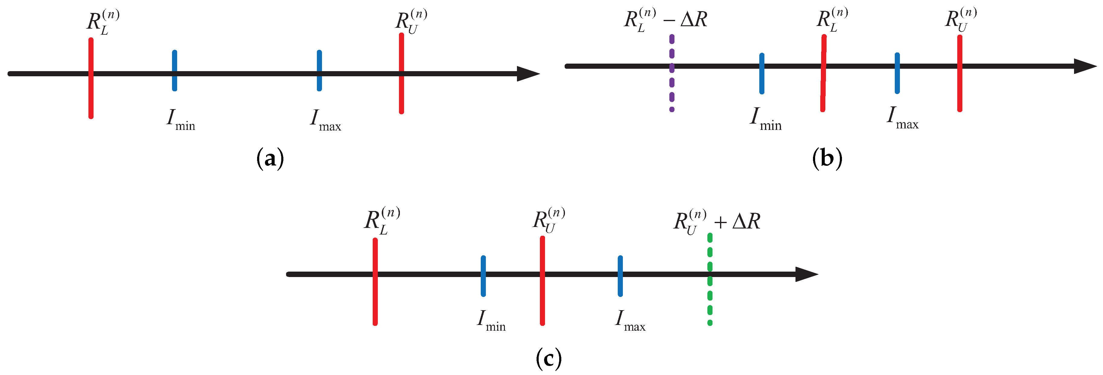
Figure 4.
The comparison of polar codes with punctured rate , , under different puncturing algorithms in the BI-AWGN channel, where the block length of the mother code is and the code-rate is : (a) BER; (b) FER.
Figure 4.
The comparison of polar codes with punctured rate , , under different puncturing algorithms in the BI-AWGN channel, where the block length of the mother code is and the code-rate is : (a) BER; (b) FER.
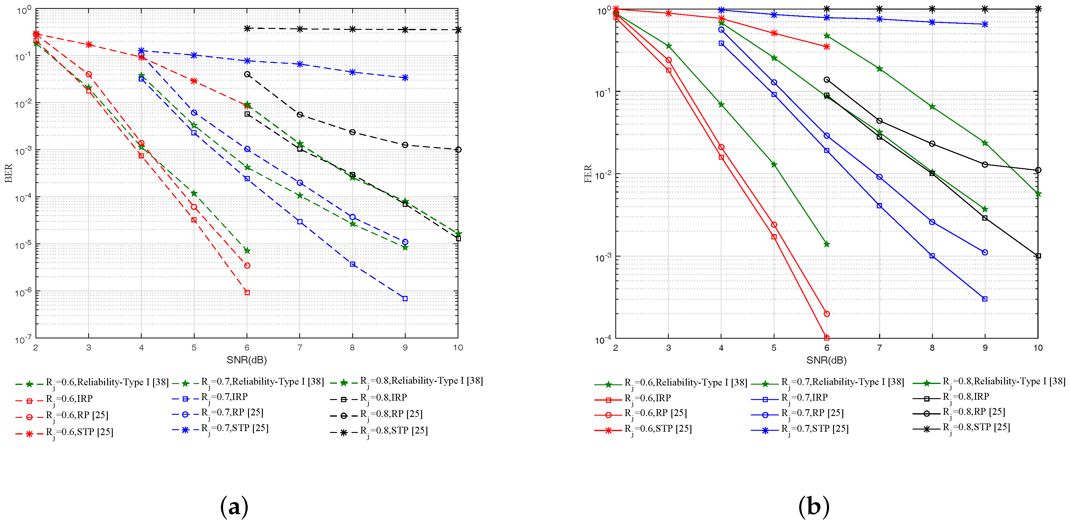
Figure 5.
The comparison of the average number of transmissions of 100 data blocks in our RC IR-HARQ scheme and the RCP scheme with initial channel capacity in three cases: (a) Case 1: ; (b) Case 2: ; (c) Case 3: .
Figure 5.
The comparison of the average number of transmissions of 100 data blocks in our RC IR-HARQ scheme and the RCP scheme with initial channel capacity in three cases: (a) Case 1: ; (b) Case 2: ; (c) Case 3: .
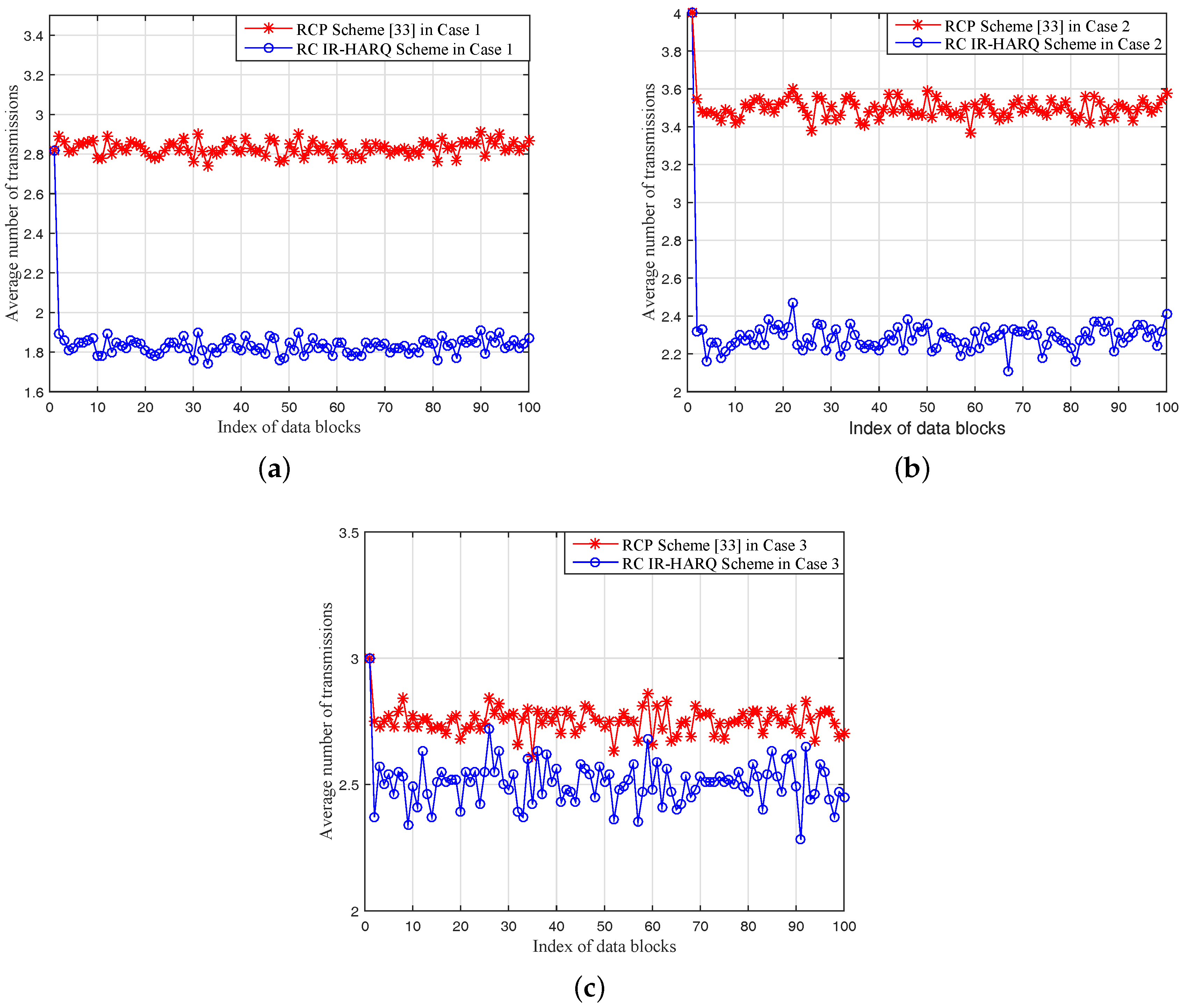
Figure 6.
The comparison of the average number of transmissions of 100 data blocks in our RC IR-HARQ scheme and the RCP scheme in Case 1 with different initial channel capacity : (a) ; (b) ; (c) ; (d) .
Figure 6.
The comparison of the average number of transmissions of 100 data blocks in our RC IR-HARQ scheme and the RCP scheme in Case 1 with different initial channel capacity : (a) ; (b) ; (c) ; (d) .

Table 1.
The relationship between the initial code-rate and the number of transmissions over a time-varying channel.
Table 1.
The relationship between the initial code-rate and the number of transmissions over a time-varying channel.
| Initial Code-Rate | Channel Capacity | Result |
|---|---|---|
| increase | transmissions at most | |
| decrease | transmissions at least | |
| increase | 1 transmission | |
| decrease | 2 transmissions at least |
Table 2.
The relationship between the optimal initial code-rate of the PCPP coding block and two key parameters.
Table 2.
The relationship between the optimal initial code-rate of the PCPP coding block and two key parameters.
| Initial Code-Rate | Channel Capacity | Value Range of | Transmission Rounds | Coding Pairs |
|---|---|---|---|---|
| Case 1: | increase | 1 | 1 | |
| 2 | 2 | |||
| decrease | 2 | 2 | ||
| Case 2: | increase | 1 | 1 | |
| 2 | 2 | |||
| decrease | 2 | 2 | ||
| 3 | 3 | |||
| Case 3: | increase | 1 | 1 | |
| 2 | 1 | |||
| 3 | 2 | |||
| decrease | 2 | 2 | ||
| 3 | 2 |
Table 3.
Simulation parameters of the puncturing algorithms.
| Parameters | Value |
|---|---|
| Block length of mother polar codes | 1024 |
| Mother polar code-rate | 0.5 |
| Punctured polar code-rates | 0.6, 0.7, 0.8 |
| Polar codes decoder | SCL |
| Modulation | BPSK |
SCL: SCL decoding; BPSK: Binary Phase Shift Keying.
Table 4.
Simulation parameters of the IR-HARQ transmission scheme.
| Parameters | Value |
|---|---|
| The initial code-rate of the first data block | 0.8 |
| Variation range of the channel capacity | |
| The number of data blocks | 100 |
| The simulation times for each data block | 100 |
| Initial channel capacity in Figure 5 | 0.5 |
| Rate difference of the 3 cases in Figure 5 | Case 1: Case 2: Case 3: |
| Initial channel capacity in Figure 6 | 0.3, 0.4, 0.6, 0.7 |
| Rate difference of the Case 1 in Figure 6 | Case 1: |
© 2017 by the authors. Licensee MDPI, Basel, Switzerland. This article is an open access article distributed under the terms and conditions of the Creative Commons Attribution (CC BY) license (http://creativecommons.org/licenses/by/4.0/).
Share and Cite
MDPI and ACS Style
Jiao, J.; Wang, S.; Feng, B.; Gu, S.; Wu, S.; Zhang, Q. Design of Rate-Compatible Parallel Concatenated Punctured Polar Codes for IR-HARQ Transmission Schemes. Entropy 2017, 19, 628. https://doi.org/10.3390/e19110628
AMA Style
Jiao J, Wang S, Feng B, Gu S, Wu S, Zhang Q. Design of Rate-Compatible Parallel Concatenated Punctured Polar Codes for IR-HARQ Transmission Schemes. Entropy. 2017; 19(11):628. https://doi.org/10.3390/e19110628
Chicago/Turabian StyleJiao, Jian, Sha Wang, Bowen Feng, Shushi Gu, Shaohua Wu, and Qinyu Zhang. 2017. "Design of Rate-Compatible Parallel Concatenated Punctured Polar Codes for IR-HARQ Transmission Schemes" Entropy 19, no. 11: 628. https://doi.org/10.3390/e19110628
Note that from the first issue of 2016, this journal uses article numbers instead of page numbers. See further details here.