Strain Measurements of Composite Laminates with Embedded Fibre Bragg Gratings: Criticism and Opportunities for Research

Abstract
: Embedded optical fibre sensors are considered for structural health monitoring purposes in numerous applications. In fibre reinforced plastics, embedded fibre Bragg gratings are found to be one of the most popular and reliable solutions for strain monitoring. Despite of their growing popularity, users should keep in mind their shortcomings, many of which are associated with the embedding process. This review paper starts with an overview of some of the technical issues to be considered when embedding fibre optics in fibrous composite materials. Next, a monitoring scheme is introduced which shows the different steps necessary to relate the output of an embedded FBG to the strain of the structure in which it is embedded. Each step of the process has already been addressed separately in literature without considering the complete cycle, from embedding of the sensor to the internal strain measurement of the structure. This review paper summarizes the work reported in literature and tries to fit it into the big picture of internal strain measurements with embedded fibre Bragg gratings. The last part of the paper focuses on temperature compensation methods which should not be ignored in terms of in-situ measurement of strains with fibre Bragg gratings. Throughout the paper criticism is given where appropriate, which should be regarded as opportunities for future research.
1. Introduction
1.1. Composite Structures
There is a growing interest in the use of fibre reinforced plastics (FRPs) as high-grade construction materials that need to be lightweight, yet strong under sometimes harsh loading conditions, for various applications [1–3]. Despite the growing popularity of structural composite materials, one has to realize that their mechanical behaviour is significantly different compared to conventional isotropic construction materials. The feedback from recorded loads, deformations and temperatures of (and especially inside) existing structures in real conditions, can lead to highly valuable information for design criteria. In particular, strain monitoring of an in-service structure should greatly enhance the insight and confidence in the (long-term) behaviour of high performance composite structures.
Therefore, research is being conducted worldwide on evaluation techniques to measure strain of different types of materials and structures. A major field of research concerns the application of optical fibre sensors [4–7], which have a number of well-known advantages including insensitivity to electromagnetic interference, small dimensions, light weight, multiplexing capabilities and resistance to corrosion [8]. The compatibility of these sensors with the manufacturing process of fibrous composite materials (e.g., pultrusion [9], co-braided with braided composites [10–13], laminates [14], etc.) can be seen as an extra advantage.
Within the group of the embedded optical fibre sensors, fibre Bragg gratings (FBGs) are the most widespread for measuring the internal deformations of various types of fibrous composite structures. By integrating an FBG into a structure, it becomes very robust and it can survive the sometimes harsh environment in which FRPs are used.
1.2. Technical Issues Concerning Embedding FBGs in Composite Materials
Despite the many advantages of embedded optical fibre sensors, integrating them into structures leads to a number of specific problems which need to be tackled. A major issue is the entry point of the optical fibre lead in the composite material, which is prone to breaking. An overview of the literature on approaches to overcome this problem is given by Green et al. [15]. Two main options exist to protect the fibre egress point in composite laminates: either integrating a fibre connector at the edge or surface of the laminate [16] or integration of a fibre feed-through mechanism [17]. Both methods enable the optical fibre to be led smoothly out of the stiff laminate (surface or edge) without excessive bending and curvature. However, decades of research have enabled the research community to come up with the ideal entry point in a material which is insensitive to delamination. Perhaps one should focus on eliminating the entry point entirely by wireless transmission of data from the embedded sensor to a read-out unit. On this subject, Teitelbaum et al. focused on wireless transmission of video data via a multimode fibre in a smart structure [18,19]. In SMARTFIBER, a European FP7-project, the researchers try to miniaturize the read-out unit, so that it can be embedded in the composite material [20]. With the last two solutions, edge trimming, which is commonly needed after composite fabrication, will become possible.
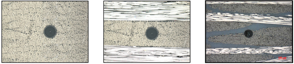
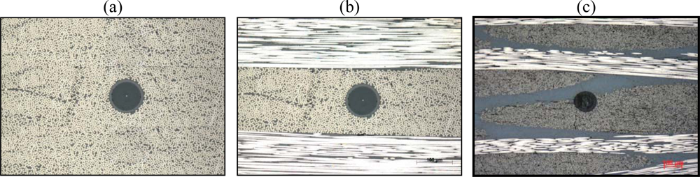
Another issue is the distortion of the composite structure in the surroundings of the optical fibre. The size of the FBG sensor ranges from 125 μm (which is a classical telecom fibre) down to 52 μm [21]. This is still one order of magnitude larger than the most commonly used reinforcement fibres (glass: 5–20 μm, carbon: 5–10 μm). Thus, the embedded optical fibre will inevitably cause a local distortion in the host material (Figure 1).
Minimizing the optical fibres will reduce the composite distortion. However, not only the mismatch in size between the optical fibres and the reinforcement fibres, but also the type of composite material which is used (uni-directional, woven fabric, stitched, braided, etc.), and the relative alignment of the optical fibre with respect to the reinforcement fibres influences the distortion. Research has proven that small diameter optical fibres do not cause any significant reduction in strength of composites and standard 125 μm optical fibres produce a minimum perturbation of the host material when embedded parallel to the reinforcing fibres in laminates [22,23]. In addition, for small diameter optical fibres, no resin-rich regions (also called resin pocket) are found around the fibre which to the contrary in some cases, can be found for embedded standard telecom optical fibres [24]. Shivakumar and Emmanwori embedded optical fibres with a relative orientation to the reinforcement fibres and found that the structural properties were not affected when the fibre was embedded parallel to the reinforcement fibres [25].
1.3. Strain Measurement Technique with Embedded FBG
The above mentioned structural strength analysis does not consider the disturbance of the strain field in the composite material. The strain field around an embedded optical fibre is significantly changed and the interfacial stresses are increased [26]. In addition, the stress/strain field present in the composite host material will differ significantly from the one present in the core of the optical fibre, due to the different mechanical properties of both materials. Several authors have accepted the challenge of measuring strains with FBGs embedded in several types of composite material for axial as well as multi-axial strain measurements. Even cure monitoring using embedded FBGs has been tackled in the literature. This review paper gives an overview of the methods to measure strain in composite materials with embedded fibre Bragg gratings and of the problems which needed to be tackled. Wherever necessary, critical notes will be made concerning the referred papers which should be seen as an opportunity for future research. It should be mentioned that the focus is on strain measurements and less on direct damage detection, though some reference to the authors concerned may occur. The paper starts by giving a short introduction on the basic principle of FBGs and how they are used to measure external strain and temperature influences.
2. Basic FBG Principle
A fibre Bragg grating is a local modulation of the refractive index in the optical fibre which can be created by an appropriate sideways illumination with UV-light (spatial fringe pattern) of a photo-sensitive optical fibre. This pattern in the core of the optical fibre can be created by using a holographic method (first introduced by Meltz et al. [27]) or a phase mask method. Both techniques can also be combined [28]. A point-by-point technique using a pulsed laser (each pulse inscribes one grating period) can be used as well. This technique is mainly used to inscribe long period gratings [29]. Although several grating types (uniform, chirped, apodized, etc.) exist, uniform FBGs will be the main focus of this review paper. When light with a broadband spectrum is coupled into a single mode (SM) optical fibre and interacts with the grating, only a small part of the light spectrum will be back reflected. The reflected spectrum is centred on the Bragg-wavelength (λB) and depends on the effective index of refraction (neff) and on the Bragg period (Λ) of the grating according to the well known Bragg equation:
2.1. Strain Sensitivity
In most cases, for FBGs written in conventional single mode optical fibres, the centre strain approximation can be used to determine the theoretical strain and temperature response [30]. Under this approximation, each Bragg peak wavelength (corresponding with the 1’- and 2’-axis, Figure 2) is dependent on the total strain field present in the core of the optical fibre sensor. Under the assumption of an isothermal condition (ΔT = 0) the wavelength shifts for small strain perturbations can be written as:
2.2. Temperature Sensitivity
Under the assumption of a strain free condition (εi = 0) the Bragg peak shift under relatively small temperature load can be written as:
Equation (3) represents the effects of temperature on the Bragg wavelength. A temperature increase causes a thermal expansion of the fibre with Bragg grating (and thus a change of its Bragg period) and also a change in the refractive index. This fractional wavelength shift for a small temperature change ΔT may be written as [33]:
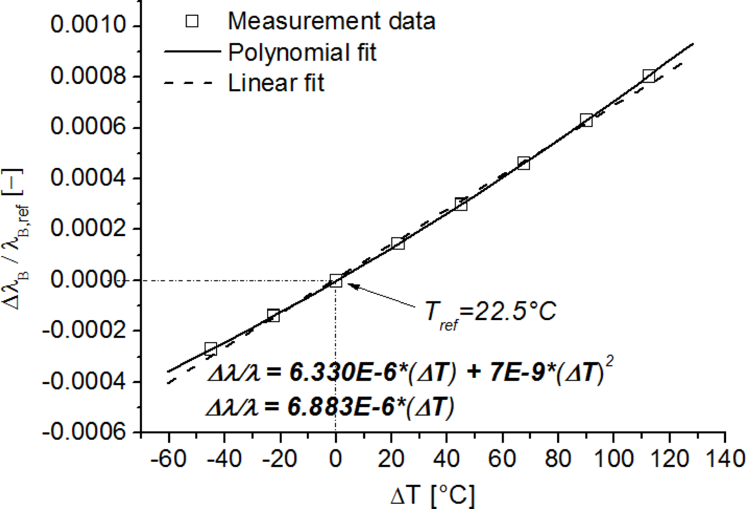
In many cases bigger temperature variations are to be expected (e.g., in cure monitoring of FRPs). Therefore, one cannot rely on the linear relation of Equation (4) anymore. Note that the expansion coefficient αf is constant over a high temperature range [37], however, the thermo-optic coefficient αn is temperature dependent (αn = αT + b, [38]). Therefore, when considering high temperature ranges, a more accurate equation is necessary. By substituting this linear dependency in Equation (4), it can be rewritten as:
Pal et al. [39] already fitted data of temperature calibrations of fibre Bragg gratings to higher order polynomials and found satisfying results for a quadratic polynomial. An example of typical non-linear effects in the temperature calibration curve of an FBG written in a Ge-doped optical fibre is shown in Figure 3. Here, the normalized wavelength shift ΔλB/λB is plotted against the temperature shift ΔT, with respect to a reference temperature (e.g., Tref = 22.5 °C). If a linear regression is used instead of a polynomial (Figure 3), large errors can be made if used when compensating strain measurements for temperature fluctuations, in for example real-life applications. For a temperature change of 120 °C, a wavelength shift error of approximately 60 pm or a longitudinal strain error of approximately 70 μstrain is introduced.
It should be apparent that any change in wavelength, associated with the action of an external perturbation to the grating, is the sum of mechanical deformation and temperature terms. Therefore, in sensing applications where only one perturbation is of interest, the de-convolution of temperature and strain becomes necessary! An overview of methods to decouple the temperature and strain cross sensitivity is given in Section 4, however, focus will first be on pure strain measurements.
3. Strain Measurements with Embedded FBGs
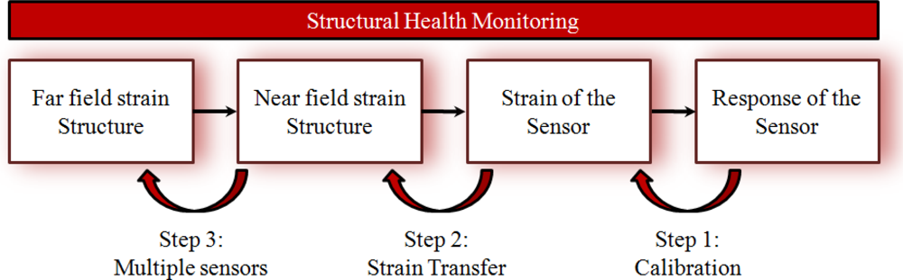
The monitoring scheme of Figure 4 gives an overview of the different steps necessary to relate the output of an embedded FBG to the strain of the structure in which it is embedded. Each step has been addressed in literature, and an overview can be found in this review paper.
When going from right to left in this monitoring scheme, the response of the sensor (Bragg wavelength shifts) should be related to the strain of the sensor (longitudinal and/or transversal). This requires a basic (theoretical and experimental) know-how on the strain dependency of FBGs written in optical fibres (step 1, calibration). The shape of the cured spectrum can play a significant role in this (Section 3.1). Secondly, since the sensor (silica glass optical fibre) and the host material (fibre reinforced plastic) have different material properties, the mechanical interaction between the embedded sensor and its host should be evaluated (this is step 2, strain transfer relationship) to determine the near field strain in the structure. In the third and final step, the strain at some discrete positions in the structure can be used as a measure for its global condition (step 3, multiple sensors), i.e., the far field strain in the structure. In this paper the authors focus on the first two steps in the scheme.
3.1. FBG Sensor Response
3.1.1. Calibration of a Non-Embedded FBG
Calibration of a non-embedded FBG, or step 1 (Figure 4) has been extensively addressed in the literature without considering the embedded situation. It should be subdivided in longitudinal strain and transversal strain calibrations. Longitudinal strain calibrations of FBGs are more or less straight-forward and therefore, only a few research results are to be reported. For example Abe et al. [41] fixed the fibre between two displacement stages, where a known deformation can be applied by a calibrated micrometer. The longitudinal strain sensitivity of an internal elliptical cladding fibre was determined. One should, however, mention that this method is not suited for locally stripped fibres. The strain will vary significantly when comparing a coated section in the fibre with the locally stripped fibre section. Hence, large errors are induced when determining the strain sensitivity. To determine the strain sensitivity of stripped FBGs, one needs to measure the applied load during calibration and relate that to the stress/strain in the fibre.
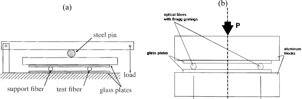
When transversal strains are envisaged a different approach is necessary. Generally, a diametrical compression test set-up is used for transversal strain calibrations (Figure 5). By applying a diametric load on an axi-symmetric optical fibre in which an FBG is inscribed, a well known state of plane strain (ε3′ = 0) is produced [42]. Then, by substituting this strain state in Equation (2) the strain-optic coefficients can be determined experimentally.
In the literature several designs for transverse strain calibrations are proposed, which can be subdivided into two main groups. The first group of authors uses a leverage arm and calibrated weights to load the fibre [30,43–46], the other group directly press the fibre with calibrated weights or with a test bench [32,42,47–50] (Figure 5). In the first group, Abe et al. [44] used two support fibres and one test fibre to quantify the effect of transverse loads on the Bragg spectrum. Two support fibres can, however, compromise the measurement, since, the load should be exactly on top of the test fibre and all fibres should have exactly the same diameter. Therefore, Wagreich et al. [43] used only one support fibre. Later, Lawrence et al. [30] and Bosia et al. [45] improved the test set-up by reducing the number of steel pins. The resulting test set-up is shown in Figure 5(a). In the second group, the differences amongst the different test set-ups are mainly related to the use of guiding pins of the load stamp [47,48] or not [32,49,50]. By removing the guiding pins, all friction is eliminated out of the system, however, when the load stamp moves during calibration, the orientation of the optical fibre (certainly for polarization maintaining fibres (PM-fibres)) becomes uncertain.
Both methods are mostly used for calibration of FBGs written in high birefringent fibres (HiBi-fibres). Often the obtained Bragg shifts are only related with the diametrical applied force (in Nmm−1) and not with the necessary induced strain field in the core of the fibre. Stress applying parts in such HiBi-fibres make it difficult to predict those strains field. Therefore, it is far from easy to define the exact strain-optic coefficients of such fibres [45]. In addition, in most of these set-ups the researchers use a single FBG and a dummy support fibre to spread the applied load. Guemes and Menendez [32] were the first to suggest the use of two FBGs to improve the accuracy of the calibration set-up. As such, averaging possible asymmetries due to misalignments in the applied loads can be done. Voet et al. [50] used the same method and found little variation in the strain-optic coefficients for draw tower gratings (DTG®s) compared to what Bertholds and Dändliker found for standard telecom fibre [51]. DTG®s are single axial fibre Bragg gratings, written in highly GeO2-doped silica fibre using a single laser shot, during the fibre drawing process [52].
3.1.2. FBG Spectral Response after Embedding
Dependent on the composite morphology, in which the FBG is embedded and the coating of the FBG, the reflected spectrum of the Bragg grating (after curing) can remain uniform, specifically distorted, or highly randomly distorted. Distortion of the FBG spectrum is mainly caused by the existence of residual strains, which build up during the composite manufacturing process. These strains exist in the absence of any external load (mechanical, and thermal).
On the microscopic level they arise from the mismatch in material properties between the (stiff) reinforcement fibres and the (soft) resin. On macroscopic level, they can arise from ply anisotropy (e.g., non balanced, non symmetric laminate). For composite structures in general, these strains play a significant role in their future mechanical performance.
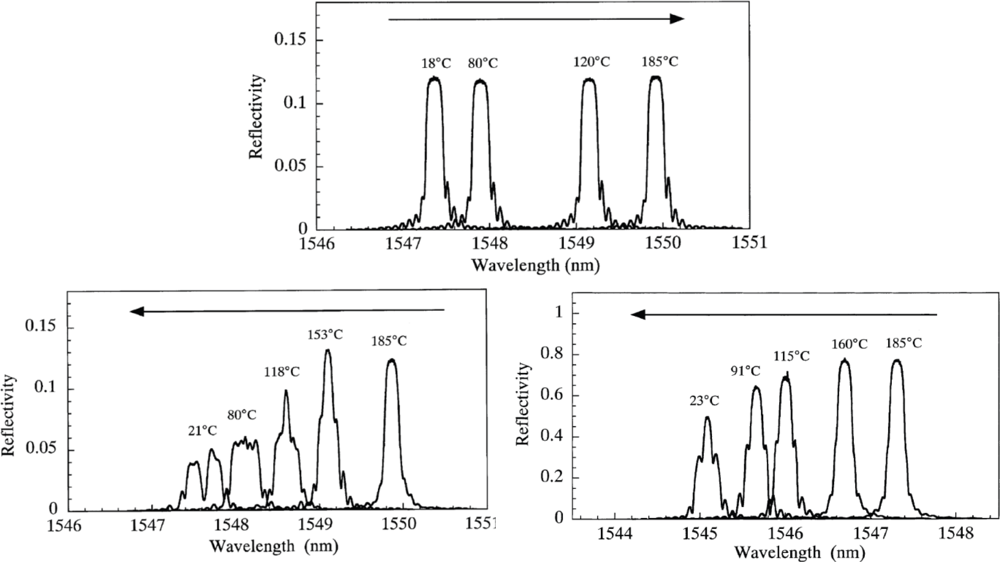
In the literature, the initiation and growth of spectral distortion has been addressed, and some examples are given. Guemes and Menéndez [32] embedded two uni-axial FBGs in a carbon/epoxy laminate with a quasi-isotropic configuration ([45,−45,0,90,0,−45,45,0,90,45,−45]2s). The fibres were embedded in between two intermediate plies parallel to the reinforcing fibres. They observed that the shape of the spectrum remained unaltered during the heating process. However, at the beginning of the cooling process, the residual strains promoted by the thermal contraction appear, which affect the spectrum and even lead to a splitting of the Bragg peak. This splitting indicates that a certain transverse strain component (Δε1′−Δε2′) has developed during the curing. Okabe et al. [53] compared the influence of the occurring residual curing strain on uncoated, polyimide coated normal and polyimide coated small diameter FBG sensors. The fibres were embedded in a cross ply laminate [02,904,02] in the 0 degree ply, in contact with the 90 degree ply. During the heating process, the shape of the spectrum of all sensors remained unaltered (Figure 6, top). During the cooling process, for the uncoated FBG sensor, birefringence effects are induced in the optical fibre, leading to a spectrum with two distinct peaks (Figure 6, bottom left). This spectral splitting was not observed for the embedded polyimide coated FBGs (Figure 6, bottom right), which indicates that a coated fibre exhibits a kind of “buffering” effect for transversal strains. Kim et al. [54] embedded an array of FBG sensors in a carbon laminate [0,45,90,−45]2s. During curing, a broadening of the spectrum could be observed, which indicates the occurrence of transverse stress.
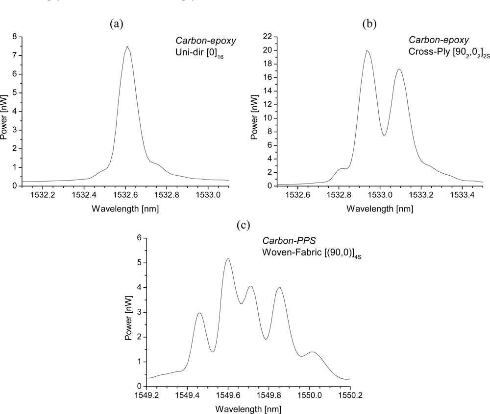
It should be clear that every type of distortion needs a different approach in determining the strain components of the structure in which the sensor is embedded. Examples of the spectral response of embedded FBGs in different FRP laminates, is shown in Figure 7. An overview of the possible methods to interpret these spectra is given in the next section.
3.1.3. Bragg Wavelength Determination
The interpretation of the spectrum in Figure 7(a) is straightforward. During a longitudinal calibration, the shift of the spectrum can directly be linked with the gauge factor of the FBG. Several methods are reported to analyze the shift of such a spectrum of which the ‘Full Width at Half Maximum’ (FWHM) algorithm and the ‘centre of gravity’ (COG), or ‘centroid’ algorithm are the most popular ones [55,56].
We note that the measurement of the Bragg-wavelength first of all depends on the stability and reproducibility of the employed interrogators. The measurement algorithm of the interrogator, however, is as important. The determination of the Bragg wavelength using a FWHM algorithm can differ from a Bragg wavelength determined by a centroid calculation algorithm. This is due to the influence of the grating characteristics (mainly uniformity of the spectral shape, amplitude) and the sampling density of the FBG spectrum, as well as on the uncertainty of the curve fit algorithm for the determination of the Bragg wavelength. An overview of other demodulation techniques, using for example tuneable filters, are reported in Zhao et al. [57].
For the second spectrum [Figure 7(b)], the occurring residual strains during the production process of a carbon-epoxy cross-ply laminate causes the spectrum to split into two well-separated Bragg peaks one for each propagation mode. It should be mentioned that the FBG used in this example is non-coated and thus not buffered from the transversal strains present in the material. As a consequence, in most loading cases, the wavelength shift of light travelling according to both eigenaxes (1′ and 2′) will differ because of a different change of the refractive index induced by the strain field present in the core of the optical fibre [Equation (2)]. Both Bragg peaks can then be monitored separately (FWHM- or COG-algorithm). By adding one [30,41,44,58–60], or several [61,62] extra FBGs, one can think of making a multi-axial strain sensor. For example, Lawrence et al. [30], and Mawatari and Nelson [58] suggest inscribing an extra grating at the position of the first grating in a PM-fibre. To obtain a working solution, the wavelength of both Bragg sensors should be chosen sufficiently separated (for example, in the 1,300 nm and 1,550 nm range). A drawback of this solution is the need for two separate light sources. In Luyckx et al. [60] this drawback is overcome by encapsulating the second grating in a capillary. As such, the second grating is isolated from transverse stresses and will react differently to external loading of the composite structure than the first grating. The capillary will, however, locally cause more distortion to the composite. In most of these research papers the suggested sensors are only calibrated without considering embedment in composite structures.
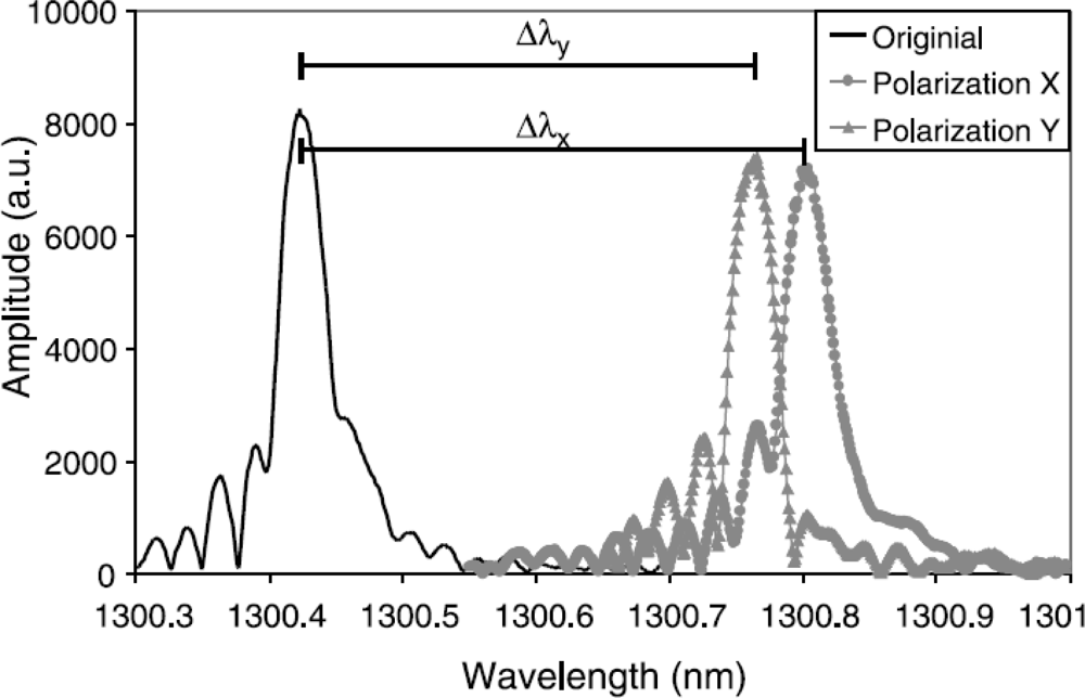
FBGs can be considered as a point sensor. However, local strain gradients (axial [63,64] as well as transversal strain [53,65–67]) can severely distort the Bragg spectrum. The difference between both is often difficult to make. A method to discriminate between both types can be found in the polarization control of the input light sent in the optical fibre [68,69] (Figure 8). Apart from this, the gradients can be related to the embedding process [70,71] of the FBG in the composite material or can originate from a specific loading case (e.g., bending [64,72]). For example Figure 7(c) represents the spectrum of an FBG embedded in a 5-harness satin weave thermoplastic composite. The axial strain profile of such a material has been numerically determined by Daggumati et al. [73]. The authors found that a clear strain gradient exist over the length of the grating and that matching axial strain results were found between the numerically determined profiles and measured profile. Kang et al. studied the response of a grating mounted on a beam which is clamped at one side and bended at the other [64]. In this way, a strain gradient is created over the length of the beam and the grating. One of the conclusions in this research is keeping the grating length as short as possible to minimize strain gradients over the grating. One should however remark that when embedded and measuring only the local strain over a short gauge distance inside a fibrous composite structure, this is not necessarily equal to the global strain of the structure [73–75].
Black et al. and Wang et al. characterized high birefringent fibres subjected to non-homogeneous transverse loads [65,76]. Under these non-homogeneous loads one of the peaks gets heavily distorted. Ling et al. simulated the reflection spectra of FBGs using the T-matrix formulation for a linear and a quadratic strain gradient [77]. This was done for small as well as for large strain gradients. Peters et al. presented a experimental verification of the response of embedded FBGs in epoxy specimens to applied non-homogeneous strain fields [78]. These strain fields could be controlled by machining the cross section of the specimen.
It is certain, that for heavily distorted FBG spectra, a simple demodulation technique such as FWHM-algorithm will not satisfy the need to quantify the global strain of a structure under load. Therefore, certain new techniques are necessary to predict the strain in a structure, and perhaps other parameters of the grating could be measured simultaneously.
A spectrum of an FBG written in a multimode optical fibre typically consists of more than one peak (dependent on the reflected modes). This forced Lim et al. to develop a cross-correlation algorithm to quantify the variation of wavelength shift caused by altering strain or temperature [79]. Caucheteur et al. developed a similar demodulation technique which evaluates the position of the reflection spectrum at the measurand (in this case temperature) with respect to the spectrum of an undisturbed sensor in the specific case of a twin Bragg grating [80]. One should note that for measurements subjected to large strain gradients a relative modulation technique will be more reliable.
3.2. Strain Transfer between Optical Fibre Sensor and Host Material
In the strain transfer step (step 2, Figure 4), a relation has to be found between the measured strain in the optical fibre and the one in the composite material. Beforehand, a clear difference should be made between uni-axial and multi-axial strain sensing.
3.2.1. Uni-Axial Strain Sensing Applications
For uni-axial strain sensing applications, the optical fibre is usually provided with a protective polymer layer, i.e., fibre coating. If one considers an embedded optical fibre, the coating will act as the interface between the optical fibre and the host material. It is clear that this can have a definite impact on the transfer of strains from the matrix to the fibre and by choosing the right coating, the strain transfer can be improved in certain principal directions. For example, it is possible to choose a coating for which stress concentrations around the fibre can be avoided and composite distortion minimize [81,82]. A lot of research on strain transfer mechanisms is related to surface mounted FBGs. One should, however, remark that the relation of the strain of the sensor to that of the substrate for surface mounted FBG strain sensors, embedded in a thin layer of adhesive, and bonded to the surface of a structure is substantially different from that of embedded strain sensors. In the first case, the adhesive layer thickness and mechanical properties of this layer have a certain influence on the strain transferred from the structure to the bonded FBG [83]. Moreover, when bonded on a thin and low-modulus substrate, the FBG could change the original strain of the substrate [84]. Wan et al. [85] found that for a surface bonded fibre, the strain transfer is dominated by: (i) adhesive thickness between the bottom of the fibre and the substrate and (ii) the bond length of the fibre. Since embedded fibres are completely surrounded by the host material, one cannot speak of bond thickness and bond length in the second case. In this matter, apparent strain gradients only exist over ∼2 mm (depending on the material properties) starting at the entry point of the embedded fibre [86].
Several authors have embedded optical fibre Bragg sensors in composite specimens to measure axial strain. In the meantime, the relationship between the axial strain of the sensor and host material is discussed. Cox [87] analytically determined the uni-axial strain transfer for the case of a finite length cylindrical inclusion embedded into an isotropic material subjected to an axially constant strain field. This theory is often referred to as the shear-lag analysis, because the axial strain of the host material is transferred through the shear strain in the interface coating/optical fibre. However, this theory does not consider the mechanical properties of the host material. Afterwards, several authors improved the shear-lag theory. For example, Jiang et al. [88] developed formulas to predict the strain field distributions of fibre and host material by combining the shear-lag theory and the theory of elasticity. In 2009, Li et al. [89] gave an overview of the parameters (mechanical properties of the coating and host material, and the gauge length of the FBG) which can affect the strain transfer. Anyhow, the above referred literature proves the necessity of in-situ calibration of the gauge factor of embedded optical fibre sensors.
In some cases no coating (recoating) at the location of the FBG is chosen in axial strain sensing applications. As such, the strain acts directly onto the cladding’s surface of the optical fibre sensor. Fan et al. [90] determined experimentally the influence of the additionally induced radial strain in optical fibres when embedding them in a host material. The authors tried to quantify this mismatch by producing two [08,904]s composite specimens in which two FBGs were embedded; one along the 0 degree direction and one along the 90 degree direction. Measurement errors up to 8% were found when using the bare FBGs gauge factor for axial strain. To correct this gauge factor, the authors suggested to use a coefficient which is dependent on the type of load, +3% for tensile loads and −8% for compressive loads. Care should, however, be taken by introducing correction coefficients which are dependent on the type or direction of the load.
3.2.2. Multi-Axial Strain Sensing Applications
Nevertheless, direct strain transfer of the host material to the a optical fibre sensor without coating can be interesting in terms of multi-axial strain measurements of composite laminates. Former research activities by other authors [91,92] pointed out the need to determine the total strain field response of an embedded FBG in a host material. Bosia et al. [45] studied the response of a sensor embedded in an epoxy specimen experiencing biaxial loading. Finite elements showed the stress distribution in the vicinity of the embedded fibre. The difference in transverse strain of the host material and embedded sensor was evaluated for transversally applied loads. It proves the necessity of a multi-axial strain transfer approach in such situations. Prabhugoud and Peters [93] predicted the spectral response of an (embedded) FBG under a multi-axial strain field through a combined opto-mechanical study. Even the FBG spectral response for non-uniform strain and stress in the laminate could be predicted. The reverse problem, however, was not tackled. Kollar and Vansteenkiste [94] developed an analytical model of the multi-axial strain transfer between an embedded optical fibre and an infinite anisotropic host material. The stress and strain relationships where derived for loading and boundary conditions applied at infinity. However, composites can be relatively thin and the lay-up of the laminate and the position of the sensor in a certain layer should be taken into account to improve multi-axial measurements with optical fibres [40,50]. At the moment, an experimental approach is still non existing, although, the author believes that multi-axial strain measurements can be of added value in monitoring the structural integrity of composites.
It should be mentioned that the risk of fibre breakage when handling a stripped fibre is high, certainly with respect to embedding of the FBG. By using coated fibre sensors this risk can be diminished.
4. Temperature Compensation
The sections above have elaborated mainly on the effect on the FBG-spectrum of homogenous and non-homogenous strains, and on how this affects the method of measuring the Bragg peak wavelength shift, and on the influence of the strain transfer (longitudinal as well as transverse) with respect to the measured strain field with the optical fibre sensor, considering an atmosphere with constant temperature. However, since for FBGs a cross-sensitivity for the strain and temperature exists, one has to find solutions to compensate the strain for temperature effects. Several methods are studied in literature, a short overview is given below. For each solution, one can check if it is suitable for embedded strain sensing applications.
4.1. Extra Strain-Free Reference (FBG) Sensor
The most simple method is measuring the temperature with an external temperature sensor and then using it to compensate the intrinsic temperature effects of the embedded grating. A reference FBG can, for example, be used as an external temperature sensor. An extra strain free FBG is added in the measurement system [95–97] and discrimination between strain and temperature can be done by separately evaluating the Bragg wavelength shifts of both FBGs (ΔλB,1,ΔλB,2) with their respective strain and temperature sensitivity (kε,kT):
Although not necessary for temperature compensation, the use of an identical FBG makes compensation very easy by just subtracting the wavelength shift of the strain free sensor from the total wavelength shift of the strain sensor. For embedded strain sensors this method can be expanded by embedding an extra Bragg sensor in a strain free compensating plate which has an identical lay-up as the structure in which the strain sensor is embedded [98]. As such, one can focus only on strain fields caused by external loads. The reference FBG should be located in the same thermal environment as the strain sensor. If one only wants to compensate for the intrinsic temperature behaviour of the grating, one can think of encapsulating a reference grating and embed this in the material. This reference grating should be isolated from the existing strain field in the material by ending it strain–free inside the capillary (glass, fused silica or metal) (Figure 9) [60,99–102].
4.2. Extra FBG Imposed on a Different Strain Field
Instead of a strain free configuration, one can also think of the use of an extra grating, imposed on a different strain field than the first grating. Since both gratings are then sensitive to strain and temperature, the discrimination method of Equation (6) should be extended with extra strain and temperature coefficients:
For example, when both gratings are loaded similarly, but opposite in sign (e.g., like in a bending experiment), temperature is compensated by just subtracting both wavelength shifts and dividing the result by two [103–105]. By artificially enlarging the stiffness of the compensating grating, it will sense a different strain (by integrating it in a capillary [101], by bonding it to another dummy fibre [106], or embedding it into another material [107]). Another special configuration is introduced by Silva et al. [108]. A transversal load sensor is created by winding a grating which is written in a polarization maintaining fibre, around a classical single mode fibre with grating so both gratings will react differently to transverse load, and temperature can be discriminated. James et al. [109] proposed a sensor configuration with an extra grating written in an optical fibre with a smaller diameter spliced to the first FBG (strain sensor). The same effect can be reached by etching the fibre at the grating position so that it becomes smaller [110]. However, it should be mentioned that, these configurations are prone to breaking during the embedding process and lose all of their efficiency (like any of the extra grating configuration discussed before) when considering the embedded situation.
4.3. Extra FBGs Which React Differently to the Same Strain Field
Another technique is adding an extra grating which reacts differently to the same strain field. This can be done by using different FBG types which have different temperature-induced wavelength shifts [111–114], or by using a second grating which is differently doped than the first one [115–118]. A lot of research has been done on the fabrication of hybrid sensors which combine an FBG with another (‘similar’) type of sensor [119–122]. These last configurations all have in common that the demodulation of the sensor signal becomes a lot more complicated. In the last decade, researchers have also focused on discrimination of strain and temperature using Bragg gratings written in polarization maintaining (PM) and micro-structured fibres. Although a small difference exists in temperature sensitivity [48,123,124] for the Bragg peaks of FBGs written in classical PM-fibres (bow-tie, panda, and elliptical core), discriminating axial strain and temperature remains very difficult [44,60]. In classical PM-fibre, birefringence is most of the time induced by temperature dependent stress applying parts while in micro-structured fibre, this mainly originates from the micro-structure inside the fibre. Therefore, almost no difference exists in temperature sensitivity for both polarization axes of the micro-structure fibre. By subtracting both wavelength shifts, one creates a temperature-independent measurement [125,126].
Note that in most of the discussed configurations a discrimination is made between temperature and axial strain. The user should, however, be careful when the fibre Bragg grating is embedded, for example in reinforced plastics, that transversal strains act in a different way on the grating than when not embedded. In addition, note that if a second order polynomial temperature effect is considered (Section 2) which is definitely necessary for cure monitoring purposes, only the reference temperature sensor method can be used (Section 4.1).
5. Conclusions
This review paper has given an overview on how to measure strains in composite materials, using embedded fibre Bragg gratings. Although it is clear that FBGs, thanks to their compatibility with fibrous composite materials, are the best choice for embedded strain monitoring of composite materials, some side remarks were given on the difficulties to implement them in a controlled and automated manner (e.g., the fibre entry point). The strain and temperature sensitivity were briefly discussed. Attention was drawn to the non-linearity of the Bragg wavelength shift as a function of temperature for high temperature ranges.
Then, a monitoring scheme was introduced, which showed the different steps necessary to relate the output of an embedded FBG with the strain of the structure in which it is embedded. The first step is about the calibration of non-embedded FBGs. The longitudinal strain calibration is more or less straightforward. However, it should be mentioned that, when being embedded, the FBG is subjected to transverse strains (in-plane and out-of-plane) as well. Therefore, an FBG needs to be calibrated for transverse strains. Research has shown that transverse strain calibrations are difficult to control and that the wavelength shifts are difficult to relate to the induced strains, certainly in the case of high birefringent fibres. New and controlled techniques are necessary to perform a correct transverse strain calibration, which can relate the applied load to the strains in embedded FBGs. It has been shown that the back-reflected light spectrum of an FBG tends to distort during the curing process. The shape of the distortion depends on the type of composite laminate (UD, crossply, etc.) in which it has been embedded. Consequently, different Bragg wavelength determination methods are necessary. A thorough and complete overview of available methods can be found in the literature. Once the strain of the optical fibre is determined, it should be related to the strain of the composite structure. In this matter, it should not be forgotten that embedded FBGs are subjected not only to longitudinal strains but to the complete internal strain field of the structure!
Last but not least, some useful temperature compensation techniques for embedded FBG strain monitoring are discussed. A conclusion is that, if the non-linearity of the wavelength shift as function of temperature is considered (Section 2), the only possible method is the reference temperature sensor method. It should be clear from this review paper that a lot of effort has gone into to making FBG-sensors the best to measure internal strains of composite structures. However, despite the enormous effort, several difficulties remain for research to overcome.
Acknowledgments
The authors wish to thank the European Commission for their financial support for the SMARTFIBER FP7-project.
References and Notes
- Airbus. Available online: http://www.airbus.com/en/aircraftfamilies/a350/advanced_materials.html (accessed on 27 December 2010).
- Gebremichael, Y.M.; Li, W.; Boyle, W.J.O.; Meggitt, B.T.; Grattan, K.T.V.; McKinley, B.; Fernando, G.F.; Kister, G.; Winter, D.; Canning, L.; Luke, S. Integration and assessment of fibre Bragg grating sensors in an all-fibre reinforced polymer composite road bridge. Sens. Actuat. A Phys 2005, 118, 78–85. [Google Scholar]
- Microcosm, Available online: http://www.smad.com/42_inch_tank_pressrelease.pdf (accessed on 27 December 2010).
- Degrieck, J.; De Waele, W.; Verleysen, P. Monitoring of fibre reinforced composites with embedded optical fibre Bragg sensors, with application to filament wound pressure vessels. NDT E Int 2001, 34, 289–296. [Google Scholar]
- De Baere, I.; Voet, E.; Van Paepegem, W.; Vlekken, J.; Cnudde, V.; Masschaele, B.; Degrieck, J. Strain monitoring in thermoplastic composites with optical fiber sensors: Embedding process, visualization with micro-tomography, and fatigue results. JTCM 2007, 20, 453–472. [Google Scholar]
- Degrieck, J.; Van Paepegem, W.; Cnudde, V.; De Baere, I.; De Baets, P.; Declercq, N.; Luyckx, G.; Masschaele, B.; Moentjens, A.; Quintelier, J.; Sol, H.; Van Hemelrijck, D.; Vlekken, J. Monitoring of fatigue, impact and wear in Cetex TPC, Cetex—Thermoplastic composites. From scratch to flight. Proceedings of the First Cetex Conference, Delft, The Netherlands, 14 June 2006; pp. 51–61.
- de Oliveira, R.; Ramos, C.A.; Marques, A.T. Health monitoring of composite structures by embedded FBG and interferometric Fabry-Pérot sensors. Comput. Struct 2008, 86, 340–346. [Google Scholar]
- Othonos, A.; Kalli, K. Fiber Bragg Gratings: Fundamentals and Applications in Telecommunications and Sensing; Artech House: Norwood, MA, USA, 1999. [Google Scholar]
- Kalamkarov, A.L.; Fitzgerald, S.B.; MacDonald, D.O.; Georgiades, A.V. The mechanical performance of pultruded composite rods with embedded fiber-optic sensors. Compos. Sci. Tech 2000, 60, 1161–1169. [Google Scholar]
- Li, X.H.; Zhao, C.S.; Lin, J.; Yuan, S.F. The internal strain of three-dimensional braided composites with co-braided FBG sensors. Opt. Lasers Eng 2007, 45, 819–826. [Google Scholar]
- Yuan, S.F.; Huang, R.; Rao, Y.J. Internal strain measurement in 3D braided composites using co-braided optical fiber sensors. J. Mater. Sci. Technol 2004, 20, 199–202. [Google Scholar]
- Jung, K.; Kang, T.J. Cure monitoring and internal strain measurement of 3-D hybrid braided composites using fiber Bragg grating sensor. J. Compos. Mater 2007, 41, 1499–1519. [Google Scholar]
- Jung, K.; Kang, T.J.; Lee, B.; Kim, Y. Estimation of residual strain and stress in interply hybrid composite using fiber bragg grating sensor. Fiber. Polym 2007, 8, 438–442. [Google Scholar]
- Mulle, M.; Collombet, F.; Olivier, P.; Grunevald, Y.H. Assessment of cure residual strains through the thickness of carbon-epoxy laminates using FBGs, Part I: Elementary specimen. Compos. A Appl. Sci. Manufact 2009, 40, 94–104. [Google Scholar]
- Green, A.K.; Shafir, E. Termination and connection methods for optical fibres embedded in aerospace composite components. Smart Mater. Struct 1999, 8, 269–273. [Google Scholar]
- Sjogren, B.A. Static strength of CFRP laminates with embedded fiber-optic edge connectors. Compos. A Appl. Sci. Manufact 2001, 32, 189–196. [Google Scholar]
- Green, A.K.; Zaidman, M.; Shafir, E.; Tur, M.; Gali, S. Infrastructure development for incorporating fibre-optic sensors in composite materials. Smart Mater. Struct 2000, 9, 316–321. [Google Scholar]
- Teitelbaum, M.E.; O’Brien, D.J.; Wetzel, E.D.; Goossen, K.W. Passive and Active Data Porting to Composite Integrated Optical Fibers via Integrated Optics. Proceedings of Conference on Active and Passive Smart Structures and Integrated Systems, San Diego, CA, USA, 10–13, March 2008; pp. Q9282–Q9282.
- Teitelbaum, M.E.; Yarlagadda, S.; O’Brien, D.J.; Wetzel, E.D.; Goossen, K.W. Normal incidence free space optical data porting to embedded communication links. IEEE Trans. Compon. Packag. Tech 2008, 31, 32–38. [Google Scholar]
- SMARTFIBER—European FP7 project. Available online: http://www.smartfiber-fp7.eu/ (accessed on 27 December 2010).
- Takeda, N.; Okabe, Y.; Kuwahara, J.; Kojima, S.; Ogisu, T. Development of smart composite structures with small-diameter fiber Bragg grating sensors for damage detection: Quantitative evaluation of delamination length in CFRP laminates using Lamb wave sensing. Compos. Sci. Tech 2005, 65, 2575–2587. [Google Scholar]
- Saton, K.; Fukuchi, K.; Kurosawa, Y.; Hongo, A.; Takeda, N. Polyimide-Coate Small-Diameter Optical Fiber Sensors for Embedding in Composite Laminate Structures; SPIE: Newport Beach, CA, USA, 2001; pp. 285–294. [Google Scholar]
- Jensen, D.W.; Sirkis, J.S. Integrity of composite structures with embedded optical fibers. In Fiber Optic Smart Structures; Udd, E., Ed.; Wiley: New York, NY, USA, 1995; pp. 109–129. [Google Scholar]
- Leka, L.G.; Bayo, E. A close look at the embedment of optical fibers into composite structures. J. Compos. Tech. Res 1989, 11, 106–112. [Google Scholar]
- Shivakumar, K.; Emmanwori, L. Mechanics of failure of composite laminates with an embedded fiber optic sensor. J. Compos. Mater 2004, 38, 669–680. [Google Scholar]
- Jensen, D.W.; Pascual, J.; August, J.A. Finite Element Analysis of Composite Laminates Containing Transversely Embedded Optical Fiber Sensors. Proceedings of ECCM-1: First European Conference on Smart Structures and Materials, Glasgow, UK; SPIE: Glasgow, UK; pp. 115–122.
- Meltz, G.; Morey, W.W.; Glenn, W.H. Formation of Bragg gratings in optical fibers by a transverse holographic method. Opt. Lett 1989, 14, 823–825. [Google Scholar]
- Dockney, M.L.; James, S.W.; Tatam, R.P. Fibre Bragg gratings fabricated using a wavelength tuneable laser source and a phase mask based interferometer. Meas. Sci. Tech 1996, 7, 445–448. [Google Scholar]
- Malo, B.; Hill, K.O.; Bilodeau, F.; Johnson, D.C.; Albert, J. Point-by-point fabrication of micro-Bragg gratings in photosensitive fiber using single excimer pulse refractive-index modification techniques. Electron. Lett 1993, 29, 1668–1669. [Google Scholar]
- Lawrence, C.M.; Nelson, D.V.; Udd, E.; Bennett, T. A fiber optic sensor for transverse strain measurement. Experiment. Mech 1999, 39, 202–209. [Google Scholar]
- De Waele, W. Structural monitoring of composite elements using optical fibres with Bragg-sensors. Ph.D. Thesis,. Department of Mechanical Construction and Production, Ghent University, Ghent, Belgium, 2002. [Google Scholar]
- Guemes, J.A.; Menendez, J.M. Response of Bragg grating fiber-optic sensors when embedded in composite laminates. Compos. Sci. Tech 2002, 62, 959–966. [Google Scholar]
- Butter, C.D.; Hocker, G.B. Fiber optics strain gauge. Appl. Opt 1978, 17, 2867–2869. [Google Scholar]
- Fibercore. Available online: http://www.fibercore.com (accessed on 27 December 2010).
- Sugden, K.; Zhang, L.; Williams, J.A.R.; Fallon, R.W.; Everall, L.A.; Chisholm, K.E.; Bennion, I. Fabrication and characterization of bandpass filters based on concatenated chirped fiber gratings. J. Lightw. Tech 1997, 15, 1424–1432. [Google Scholar]
- Hagemann, V.J. Untersuchungen zum dynamischen Einzelpuls-Einschreiben von Faser-Bragg-Gittern un zu deren Anwendung. Friedrich-Schiller University: Jena, Germany, 2001. [Google Scholar]
- Kühn, B.; Schadrack, R. Thermal expansion of synthetic fused silica as a function of OH content and fictive temperature. J. Non-Cryst. Solid 2009, 355, 323–326. [Google Scholar]
- Leviton, D.B.; Frey, B.J. Temperature-dependent absolute refractive index measurements of synthetic fused silica. Available online: http://ntrs.nasa.gov/archive/nasa/casi.ntrs.nasa.gov/20070018851_2007019043.pdf (accessed on 27 December 2010).
- Pal, S.; Sun, T.; Grattan, K.T.V.; Wade, S.A.; Collins, S.F.; Baxter, G.W.; Dussardier, B.; Monnom, G. Non-linear temperature dependence of Bragg gratings written in different fibres, optimised for sensor applications over a wide range of temperatures. Sens. Actuat. A Phys 2004, 112, 211–219. [Google Scholar]
- Luyckx, G.; Voet, E.; De Waele, W.; Degrieck, J. Multi-axial strain transfer from laminated CFRP composites to embedded Bragg sensor: I. Parametric study. Smart Mater. Struct 2010, 19, 105017. [Google Scholar]
- Abe, I.; Kalinowski, H.J.; Frazao, O.; Santos, J.L.; Nogueira, R.N.; Pinto, J.L. Superimposed Bragg Gratings in High-Birefringence Fibre Optics: Three-Parameter Simultaneous Measurements. Proceedings of 16th International Conference on Optical Fibre Sensor (OFS-16), Nara City, Japan, 14–17 October 2003; pp. 1453–1457.
- Fernandez, A.F.; Ottevaere, H.; Van Ierschot, C.; Panajatov, K.; Berghmans, F.; Thienpont, H. Multi-Parameter Force Sensing with Fiber Bragg Grating Sensors. Proceedings of Symposium IEEE/LEOS Benelux Chapter, Amsterdam, The Netherlands, December 2002.
- Wagreich, R.B.; Atia, W.A.; Singh, H.; Sirkis, J.S. Effects of diametric load on fibre Bragg gratings fabricated in low birefringent fibre. Electron. Lett 1996, 32, 1223–1224. [Google Scholar]
- Abe, I.; Frazao, O.; Schiller, M.W.; Nogueira, R.N.; Kalinowski, H.J.; Piinto, J.L. Bragg gratings in normal and reduced diameter high birefringence fibre optics. Meas. Sci. Tech 2006, 17, 1477–1484. [Google Scholar]
- Bosia, F.; Giaccari, P.; Botsis, J.; Facchini, M.; Limberger, H.G.; Salathe, R.P. Characterization of the response of fibre Bragg grating sensors subjected to a two-dimensional strain field. Smart Mater. Struct 2003, 12, 925–934. [Google Scholar]
- Udd, E.; Schulz, W.L.; Seim, J.M. Measurement of multidimensional strain fields using fiber grating sensors for structural monitoring. Proceedings of the SPIE Conference on Fiber Optic Sensor Technology and Applications, Boston, MA, USA, 20–22 September 1999; pp. 24–34.
- Ye, C.C.; Staines, S.E.; James, S.W.; Tatam, R.P. A polarization-maintaining fibre Bragg grating interrogation system for multi-axis strain sensing. Meas. Sci. Tech 2002, 13, 1446–1449. [Google Scholar]
- Chehura, E.; Ye, C.C.; Staines, S.E.; James, S.W.; Tatam, R.P. Characterization of the response of fibre Bragg gratings fabricated in stress and geometrically induced high birefringence fibres to temperature and transverse load. Smart Mater. Struct 2004, 13, 888–895. [Google Scholar]
- Suo, R.; Chen, X.F.; Zhou, K.M.; Zhang, L.; Bennion, I. In-Fibre Directional Transverse Loading Sensor based on Excessively Tilted Fibre Bragg Gratings. Proceedings of 19th International Conference on Optical Fibre Sensors, Perth, Australia, 15–18 April 2008.
- Voet, E.; Luyckx, G.; De Waele, W.; Degrieck, J. Multi-axial strain transfer from laminated CFRP composites to embedded Bragg sensor: II. Experimental validation. Smart Mater. Struct 2010, 19, 105018. [Google Scholar]
- Bertholds, A.; Dandliker, R. Determination of the individual strain-optic coefficients in single mode optical fibers. J. Lightw. Tech 1988, 6, 17–20. [Google Scholar]
- Chojetzki, C.; Rothhardt, M.; Ommer, J.; Unger, S.; Schuster, K.; Mueller, H.R. High-reflectivity draw-tower fiber Bragg gratings—Arrays and single gratings of type II. Opt. Eng 2005, 44, 060503. [Google Scholar]
- Okabe, Y.; Yashiro, S.; Tsuji, R.; Mizutani, T.; Takeda, N. Effect of thermal residual stress on the reflection spectrum from fiber Bragg grating sensors embedded in CFRP laminates. Compos. A Appl. Sci. Manufact 2002, 33, 991–999. [Google Scholar]
- Kim, B.; Nesbitt, A.; Walker, W. Optimization and Strain Measurements of FBG Sensors Embedded in Carbon Composites. Proceedings of ECCM 13: 13rd European Conference on Composite Materials, Stockholm, Sweden; 2008; p. 107. [Google Scholar]
- Dyer, S.D.; Williams, P.A.; Espejo, R.J.; Kofler, J.D.; Etzel, S.M. Key metrology considerations for riber Bragg grating sensors. In Smart Structures and Materials 2004: Smart Sensor Technology and Measurement Systems; Udd, E., Inaudi, D., Eds.; SPIE: Bellingham, WA, USA, 2004; Volume 5384, pp. 181–189. [Google Scholar]
- Fernandez, A.F.; Gusarov, A.; Berghmans, F.; Kalli, K.; Polo, V.; Limberger, H.; Beukema, M.; Nellen, P. Round-robin for fibre Bragg grating metrology during COST270 action. In Reliability of Optical Fiber Components, Devices, Systems, and Networks II; Limberger, H.G., Matthewson, M.J., Eds.; SPIE: Bellingham, WA, USA, 2004; Volume 5465, pp. 210–216. [Google Scholar]
- Zhao, Y.; Liao, Y.B. Discrimination methods and demodulation techniques for fiber Bragg grating sensors. Opt. Lasers Eng 2004, 41, 1–18. [Google Scholar]
- Mawatari, T.; Nelson, D. A multi-parameter Bragg grating fiber optic sensor and triaxial strain measurement. Smart Mater. Struct 2008, 17, 035033. [Google Scholar]
- Udd, E.; Nelson, D.; Lawrence, C. Three Axis Strain and Temperature Fiber Optic Grating Sensor. Proceedings of the Conference on Smart Sensing, Processing, and Instrumentation—Smart Structures and Materials 1996, San Diego, CA, USA, 26–28 February 1996; pp. 104–109.
- Luyckx, G.; De Waele, W.; Degrieck, J.; Van Paepegem, W.; Vlekken, J.; Vandamme, S.; Chah, K. Three-dimensional strain and temperature monitoring of composite laminates. Insight 2007, 49, 10–16. [Google Scholar]
- Matrat, J.; Levin, K.; Jarlas, R. Implementation of a Bragg Grating Strain Rosette Embedded in Composites. Proceedings of the Smart Structures and Materials Conference 2001, Newport Beach, CA, USA, 5–8 March 2001; pp. 168–179.
- Levin, K.; Matrat, J. Strain Measurements Using an Interferometrically Interrogated Embedded Fibre Optic Rosette. Proceedings of the 3rd European Workshop on Optical Fibre Sensors, Naples, Italy, 4–6 July 2007; pp. 61945–61945.
- Kuang, K.S.C.; Kenny, R.; Whelan, M.P.; Cantwell, W.J.; Chalker, P.R. Residual strain measurement and impact response of optical fibre Bragg grating sensors in fibre metal laminates. Smart Mater. Struct 2001, 10, 338–346. [Google Scholar]
- Kang, D.H.; Park, S.O.; Hong, C.S.; Kim, C.G. The signal characteristics of reflected spectra of fiber Bragg grating sensors with strain gradients and grating lengths. NDT E Int 2005, 38, 712–718. [Google Scholar]
- Black, K.; Udd, E.; Schulz, W.; Kreger, S.; Kunzler, M.; Taylor, T.; Lumsden, R. Using Multi-Axis Fiber Grating Strain Sensors to Measure Transverse Strain and Transverse Strain Gradients in Composite Materials with Complex Weave Structures; SPIE: Bellingham, WA, USA, 2002. [Google Scholar]
- Michaille, L.; McCall, M.W.; Lai, Y.C.; Williams, J.A.R. Analysis of single and multiple, non-permanent, tunable, birefringent spectral holes in a fibre-Bragg grating stop-band produced via uniaxial pressure. Opt. Commun 2003, 222, 1–8. [Google Scholar]
- Torres, P.; Valente, L.C.G. Spectral response of locally pressed fiber Bragg grating. Opt. Commun 2002, 208, 285–291. [Google Scholar]
- Yamate, T.; Schroeder, R.J.; Ramos, R.T.; Udd, E. Seperation method of dual peaks produced by birefringence using polarization control. Proceedings of OFS 16, Nara, Japan, 13–17 October 2003; pp. 64–67.
- Sorensen, L.; Gmur, T.; Botsis, J. Residual strain development in an AS4/PPS thermoplastic composite measured using fibre Bragg grating sensors. Proceedings of 2nd International Conference on Composites Testing and Model Identification, Bristol, England, 21–23 September 2004; pp. 270–281.
- Ivanov, D.S.; Lomov, S.V.; Ivanov, S.G.; Verpoest, I. Stress distribution in outer and inner plies of textile laminates and novel boundary conditions for unit cell analysis. Compos. A Appl. Sci. Manufact 2010, 41, 571–580. [Google Scholar]
- Summerscales, J.; Russell, P.M. Observations on the fibre distribution and fibre strain in a woven fabric reinforcement. Adv. Compos. Lett 2004, 13, 135–139. [Google Scholar]
- Tao, X.; Tang, L.; Du, W.-C.; Choy, C.-L. Internal strain measurement by fiber Bragg grating sensors in textile composites. Compos. Sci. Tech 2000, 60, 657–669. [Google Scholar]
- Daggumati, S.; Voet, E.; Van Paepegem, W.; Degrieck, J.; Xu, J.; Lomov, S.V. Local strain in a 5-harness satin weave composite under static tension: part I—Experimental analysis. Compos. Sci. Tech 2010. in review.. [Google Scholar]
- Lang, E.J.; Chou, T.W. The effect of strain gage size on measurement errors in textile composite materials. Compos. Sci. Tech 1998, 58, 539–548. [Google Scholar]
- Vieira, A.; de Oliveira, R.; Frazão, O.; Baptista, J.M.; Marques, A.T. Effect of the recoating and the length on fiber Bragg grating sensors embedded in polymer composites. Mater. Design 2009, 30, 1818–1821. [Google Scholar]
- Wang, Y.P.; Yun, B.F.; Chen, N.; Cui, T.P. Characterization of a high birefringence fibre Bragg grating sensor subjected to non-homogeneous transverse strain fields. Meas. Sci. Tech 2006, 17, 939–942. [Google Scholar]
- Ling, H.Y.; Lau, K.T.; Jin, W.; Chan, K.C. Characterization of dynamic strain measurement using reflection spectrum from a fiber Bragg grating. Opt. Comm 2007, 270, 25–30. [Google Scholar]
- Peters, K.; Pattis, P.; Botsis, J.; Giaccari, P. Experimental verification of response of embedded optical fiber Bragg grating sensors in non-homogeneous strain fields. Opt. Lasers Eng 2000, 33, 107–119. [Google Scholar]
- Lim, J.; Yang, Q.P.; Jones, B.E.; Jackson, P. R. Strain and temperature sensors using multimode optical fiber Bragg gratings and correlation signal processing. IEEE Trans. Instrum. Meas 2002, 51, 622–627. [Google Scholar]
- Caucheteur, C.; Chah, K.; Lhomme, F.; Blondel, M.; Megret, P. Autocorrelation demodulation technique for fiber Bragg grating sensor. IEEE Photon. Tech. Lett 2004, 16, 2320–2322. [Google Scholar]
- Dasgupta, A.; Sirkis, J.S. Importance of coatings to optical fiber sensors embedded in smart structures. AIAA J 1992, 30, 1337–1343. [Google Scholar]
- Sirkis, J.S.; Dasgupta, A. Optimal coating for intelligent structure fiber optical sensors. Proceedings of Conference on Fiber Optic Smart Structures and Skins 3, San Jose, CA, USA, 19–21 September 1990; pp. 129–140.
- Cheng, C.C.; Lo, Y.L.; Pun, B.S.; Chang, Y.M.; Li, W.Y. An investigation of bonding-layer characteristics of substrate-bonded fiber Bragg grating. J. Lightw. Tech 2005, 23, 3907–3915. [Google Scholar]
- Li, W.Y.; Cheng, C.C.; Lo, Y.L. Investigation of strain transmission of surface-bonded FBGs used as strain sensors. Sens. Actuat. A Phys 2009, 149, 201–207. [Google Scholar]
- Wan, K.T.; Leung, C.K.Y.; Olson, N.G. Investigation of the strain transfer for surface-attached optical fiber strain sensors. Smart Mater. Struct 2008, 17, 035037. [Google Scholar]
- Chang, C.C.; LeBlanc, M.; Vohra, S. Investigation of Transverse Stress Measurements by Using Embedded Fiber BRAGG Grating Sensors Subjected to Host Poisson’s Effect. Proceedings of Smart Structures and Materials 2000 Conference, Newport Beach, CA, USA, 5–9 March 2000; pp. 472–479.
- Cox, H.L. The elasticity and strength of paper and other fibrous materials. Br. J. Appl. Phys 1952, 3, 72–79. [Google Scholar]
- Jiang, Z.G.; Lian, J.S.; Yang, D.Z.; Dong, S.G. An analytical study of the influence of thermal residual stresses on the elastic and yield behaviors of short fiber-reinforced metal matrix composites. Mater. Sci. Eng. A Struct. Mater. Propert. Microstruct. Process 1998, 248, 256–275. [Google Scholar]
- Li, H.N.; Zhou, G.D.; Ren, L.; Li, D.S. Strain transfer coefficient analyses for embedded fiber Bragg grating sensors in different host materials. J. Eng. Mech. ASCE 2009, 135, 1343–1353. [Google Scholar]
- Fan, Y.; Kahrizi, M. Characterization of a FBG strain gage array embedded in composite structure. Sens. Actuat. A Phys 2005, 121, 297–305. [Google Scholar]
- Luyckx, G.; Voet, E.; De Waele, W.; Van Paepegem, W.; Degrieck, J.; Vlekken, J. Strain monitoring of FRP elements using an embedded fibre optic sensor. Adv. Sci. Tech 2008, 56, 435–440. [Google Scholar]
- Voet, E.; Luyckx, G.; Degrieck, J. Response of embedded fibre Bragg gratings: Strain transfer effects. Proceedings of OFS 20, Edinbrugh, UK; 2009. [Google Scholar]
- Prabhugoud, M.; Peters, K. Finite element model for embedded fiber Bragg grating sensor. Smart Mater. Struct 2006, 15, 550–562. [Google Scholar]
- Kollar, L.P.; Van Steenkiste, R.J. Calculation of the stresses and strains in embedded fiber optic sensors. J. Compos. Mater 1998, 32, 1647–1679. [Google Scholar]
- Kim, M.J.; Kim, Y.H.; Mudhana, G.; Lee, B. H. Simultaneous measurement of temperature and strain based on double cladding fiber interferometer assisted by fiber grating pair. IEEE Photon. Tech. Lett 2008, 20, 1290–1292. [Google Scholar]
- Xu, M.G.; Archambault, J.L.; Reekie, L.; Dakin, J.P. Thermally-compensated bending gauge using surface mounted fiber gratings. Int. J. Optoelectron 1994, 9, 281–283. [Google Scholar]
- Wong, A.C.L.; Childs, P.A.; Peng, G.D. Spectrally-overlapped chirped fibre Bragg grating sensor system for simultaneous two-parameter sensing. Meas. Sci. Tech 2007, 18, 3825–3832. [Google Scholar]
- Tanaka, N.; Okabe, Y.; Takeda, N. Temperature-compensated strain measurement using fiber Bragg grating sensors embedded in composite laminates. Smart Mater. Struct 2003, 12, 940–946. [Google Scholar]
- Montanini, R.; D'Acquisto, L. Simultaneous measurement of temperature and strain in glass fiber/epoxy composites by embedded fiber optic sensors: I. Cure monitoring. Smart Mater. Struct 2007, 16, 1718–1726. [Google Scholar]
- Mulle, M.; Zitoune, R.; Collombet, F.; Olivier, P.; Grunevald, Y.H. Thermal expansion of carbon-epoxy laminates measured with embedded FBGS—Comparison with other experimental techniques and numerical simulation. Compos. A Appl. Sci. Manufact 2007, 38, 381414–381424. [Google Scholar]
- Song, M.H.; Lee, S.B.; Choi, S.S.; Lee, B.H. Simultaneous measurement of temperature and strain using two fiber Bragg gratings embedded in a glass tube. Opt. Fiber Tech 1997, 3, 194–196. [Google Scholar]
- Montanini, R.; D'Acquisto, L. Simultaneous measurement of temperature and strain in glass fiber/epoxy composites by embedded fiber optic sensors: II. Post-cure testing. Smart Mater. Struct 2007, 16, 1727–1735. [Google Scholar]
- Zhao, Y.; Liao, Y.B.; Lai, S.R. Simultaneous measurement of down-hole high pressure and temperature with a bulk-modulus and FBG sensor. IEEE Photon. Tech. Lett 2002, 14, 1584–1586. [Google Scholar]
- Sheng, H.J.; Liu, W.F.; Lin, K.R.; Bor, S.S.; Fu, M.Y. High-sensitivity temperature-independent differential pressure sensor using fiber Bragg gratings. Opt. Express 2008, 16, 16013–16018. [Google Scholar]
- Zhao, Y.; Zhao, M.G. Novel force sensor based on a couple of fiber Bragg gratings. Measurement 2005, 38, 30–33. [Google Scholar]
- Frazao, O.; Marques, L.; Marques, J.M.; Baptista, J.M.; Santos, J.L. Simple sensing head geometry using fibre Bragg gratings for strain-temperature discrimination. Opt. Commun 2007, 279, 68–71. [Google Scholar]
- Jin, L.; Zhang, W.G.; Zhang, H.; Liu, B.; Zhao, H.; Tu, Q.C.; Kai, G.Y.; Dong, X.Y. An embedded FBG sensor for simultaneous measurement of stress and temperature. IEEE Photon. Tech. Lett 2006, 18, 154–156. [Google Scholar]
- Silva, S.F.O.; Frazao, O.; Santos, J.L.; Araujo, F.M.; Ferreira, L.A. Discrimination of temperature, strain, and transverse load by using fiber Bragg gratings in a twisted configuration. IEEE Sens. J 2006, 6, 1609–1613. [Google Scholar]
- James, S.W.; Dockney, M.L.; Tatam, R.P. Simultaneous independent temperature and strain measurement using in-fibre Bragg grating sensors. Electron. Lett 1996, 32, 1133–1134. [Google Scholar]
- Yan, J.H.; Zhang, A.P.; Shao, L.Y.; Ding, J.F.; He, S. Simultaneous measurement of refractive index and temperature by using dual long-period gratings with an etching process. IEEE Sens. J 2007, 7, 1360–1361. [Google Scholar]
- Frazao, O.; Lima, M.J.N.; Santos, J.L. Simultaneous measurement of strain and temperature using type I and type IIA fibre Bragg gratings. J. Opt. A Pure Appl. Opt 2003, 5, 183–185. [Google Scholar]
- Shu, X.W.; Liu, Y.; Zhao, D.H.; Gwandu, B.; Floreani, F.; Zhang, L.; Bennion, I. Dependence of temperature and strain coefficients on fiber grating type and its application to simultaneous temperature and strain measurement. Opt. Lett 2002, 27, 701–703. [Google Scholar]
- Chehura, E.; James, S.W.; Tatam, R.P. Temperature and strain discrimination using a single tilted fibre Bragg grating. Opt. Commun 2007, 275, 344–347. [Google Scholar]
- Kang, S.C.; Kim, S.Y.; Lee, S.B.; Kwon, S.W.; Choi, S.S.; Lee, B. Temperature-independent strain sensor system using a tilted fiber Bragg grating demodulator. IEEE Photon. Tech. Lett 1998, 10, 1461–1463. [Google Scholar]
- Yoon, H.J.; Costantini, D.M.; Limberger, H.G.; Salathe, R.P.; Kim, C.G.; Michaud, V. In situ strain and temperature monitoring of adaptive composite materials. J. Intell. Mater. Syst. Struct 2006, 17, 1059–1067. [Google Scholar]
- Frazao, O.; Santos, J.L. Simultaneous measurement of strain and temperature using a Bragg grating structure written in germanosilicate fibres. J. Opt. A Pure Appl. Opt 2004, 6, 553–556. [Google Scholar]
- Guan, B.O.; Tam, H.Y.; Ho, S.L.; Chung, W.H.; Dong, X.Y. Simultaneous strain and temperature measurement using a single fibre Bragg grating. Electron. Lett 2000, 36, 1018–1019. [Google Scholar]
- Patrick, H.J.; Williams, G.M.; Kersey, A.D.; Pedrazzani, J.R.; Vengsarkar, A.M. Hybrid fiber Bragg grating/long period fiber grating sensor for strain/temperature discrimination. IEEE Photon. Tech. Lett 1996, 8, 1223–1225. [Google Scholar]
- Rao, Y.J.; Ran, Z.L.; Liao, X.; Deng, H.Y. Hybrid LPFG/MEFPI sensor for simultaneous measurement of high-temperature and strain. Opt. Express 2007, 15, 14936–14941. [Google Scholar]
- Kang, H.K.; Kang, D.H.; Hong, C.S.; Kim, C.G. Simultaneous monitoring of strain and temperature during and after cure of unsymmetric composite laminate using fibre-optic sensors. Smart Mater. Struct 2003, 12, 29–35. [Google Scholar]
- Singh, H.; Sirkis, J.S. Temperature and strain measurement by combining ILFE and Bragg grating optical fiber sensors. Experiment. Mech 1997, 37, 414–419. [Google Scholar]
- Lin, C.M.; Liu, Y.C.; Liu, W.F.; Fu, M.Y.; Sheng, H.J.; Bor, S.S.; Tien, C.L. High-sensitivity simultaneous pressure and temperature sensor using a superstructure fiber grating. IEEE Sens. J 2006, 6, 691–696. [Google Scholar]
- Chen, G.H.; Liu, L.Y.; Jia, H.Z.; Yu, J.M.; Xu, L.; Wang, W.C. Simultaneous pressure and temperature measurement using Hi-Bi fiber Bragg gratings. Opt. Commun 2003, 228, 99–105. [Google Scholar]
- Chen, G.H.; Liu, L.Y.; Jia, H.Z.; Yu, J.M.; Xu, L.; Wang, W.C. Simultaneous strain and temperature measurements with fiber Bragg grating written in novel Hi-Bi optical fiber. IEEE Photon. Tech. Lett 2004, 16, 221–223. [Google Scholar]
- Frazao, O.; Carvalho, J.P.; Ferreira, L.A.; Araujo, F.M.; Santos, J.L. Discrimination of strain and temperature using Bragg gratings in microstructured and standard optical fibres. Meas. Sci. Tech 2005, 16, 2109–2113. [Google Scholar]
- Luyckx, G.; Voet, E.; Geernaert, T.; Chah, K.; Nasilowski, T.; De Waele, W.; Van Paepegem, W.; Becker, M.; Bartelt, H.; Urbanczyk, W.; Wojcik, J.; Degrieck, J.; Berghmans, F.; Thienpont, H. Response of FBGs in Microstructured and Bow Tie Fibers Embedded in Laminated Composite. IEEE Photon. Tech. Lett 2009, 21, 1290–1292. [Google Scholar]


© 2011 by the authors; licensee MDPI, Basel, Switzerland. This article is an open access article distributed under the terms and conditions of the Creative Commons Attribution license (http://creativecommons.org/licenses/by/3.0/).
Share and Cite
Luyckx, G.; Voet, E.; Lammens, N.; Degrieck, J. Strain Measurements of Composite Laminates with Embedded Fibre Bragg Gratings: Criticism and Opportunities for Research. Sensors 2011, 11, 384-408. https://doi.org/10.3390/s110100384
Luyckx G, Voet E, Lammens N, Degrieck J. Strain Measurements of Composite Laminates with Embedded Fibre Bragg Gratings: Criticism and Opportunities for Research. Sensors. 2011; 11(1):384-408. https://doi.org/10.3390/s110100384
Chicago/Turabian StyleLuyckx, Geert, Eli Voet, Nicolas Lammens, and Joris Degrieck. 2011. "Strain Measurements of Composite Laminates with Embedded Fibre Bragg Gratings: Criticism and Opportunities for Research" Sensors 11, no. 1: 384-408. https://doi.org/10.3390/s110100384