Modeling and Characterization of the Implant Intra-Body Communication Based on Capacitive Coupling Using a Transfer Function Method

Abstract
: Implantable devices have important applications in biomedical sensor networks used for biomedical monitoring, diagnosis and treatment, etc. In this paper, an implant intra-body communication (IBC) method based on capacitive coupling has been proposed, and the modeling and characterization of this kind of IBC has been investigated. Firstly, the transfer function of the implant IBC based on capacitive coupling was derived. Secondly, the corresponding parameters of the transfer function are discussed. Finally, both measurements and simulations based on the proposed transfer function were carried out, while some important conclusions have been achieved, which indicate that the achieved transfer function and conclusions are able to help to achieve an implant communication method with the highly desirable characteristics of low power consumption, high data rate, high transmission quality, etc.1. Introduction
Intra-body communication (IBC) is a technology using the human body as transmission medium for electrical signals [1]. In general, IBC technology has two application forms: on-body IBC [2–4] and implant IBC [5,6], in which on-body IBC is used for the data exchange among electrical devices which are worn on the body [2,7], while implant IBC is used for the communication among implantable electrical devices [5].
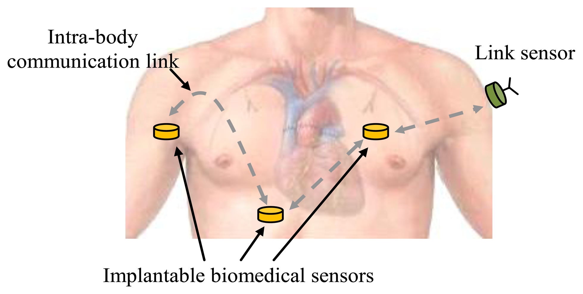
Like on-body IBC, the implant IBC provides benefits to many applications, such as biomedical monitoring systems [6,8] and other related application fields [9–11]. Compared with other implantable device communication methods [12,13], implant IBC has the advantages of low transmission power, small size, etc. [5]. Implant IBC can be applied in monitoring patient's condition and in the diagnosis and treatment of many diseases, including heart disease, neurological disorders and cancer detection [5,13,14], etc. In a biomedical monitoring system based on implant IBC, biomedical data are collected by implantable biomedical sensors located at different parts of the human body and are transmitted to other sensors using the IBC techniques, as shown in Figure 1. Finally, the data can be received and transmitted to the hospital by a link sensor, which is attached on the body, and integrated conventional wireless modules. Therefore, implant IBC is particularly important for implantable biomedical sensors to communicate with each other in biomedical monitoring system.
However, the previous works in this field have some limitations, which can be summarized as follows: (1) Comparatively higher signal attenuation. Previous investigations on implant IBC mainly concentrated on the implant IBC based on galvanic coupling [6,15], which has comparatively higher signal attenuation. In implant IBC based on galvanic coupling, an alternating current is applied with a pair of transmitter electrodes to the human tissue and detected by a pair of receiver electrodes [16,17]. Due to the fact that the two coupling electrodes of the transmitter contact with the body directly, a primary current flow between the coupler electrodes is established and only a small secondary current propagates into the conductive body parts [5]. As a result, the body effectively shorts the signal from the transmitter, which increases the signal attenuation and the power consumption, and greatly shortens the operation time of the implant [18,19]; (2) The lack of a corresponding mathematical model. As for the research of implant IBC, the corresponding mathematical model is very important for achieving the characteristics of implant IBC [16,20]. However, the previous works failed to develop the corresponding transfer function of the implant IBC. As a result, some of the implant IBC phenomena can 't be explained in theory, while other characteristics remain unrevealed so far.
On the other hand, it has been proved that on-body IBC based on capacitive coupling has comparatively lower signal attenuation. In the on-body IBC based on capacitive coupling, only the signal electrodes of the transmitter and receiver are attached to the body skin directly, while both the transmitting ground electrode and the receiving ground electrode remain floating [10,21,22]. As a result, this avoids the body shorting the signal from the transmitter and more signal energy can reach the receiver electrodes [18]. Therefore, a comparatively lower power consumption can be achieved. However, the principle of IBC based on capacitive coupling has not been used in the implant IBC so far. In this paper, an implant intra-body communication method based on capacitive coupling has been proposed, while the modeling and characterization of this kind of IBC have been investigated.
The rest of the paper is organized as follows: In Section 2, a circuit model of the implant IBC based on capacitive coupling was developed, then the corresponding transfer function was derived. Some important parameters of the transfer function were discussed and modeled in detail in Section 3. In Section 4, measurement experiments were carried out for verifying the reliability of the proposed transfer function, while some important characteristics of the proposed method were studied. Finally, Section 5 concludes this paper.
2. Transfer Function
2.1. Circuit Model
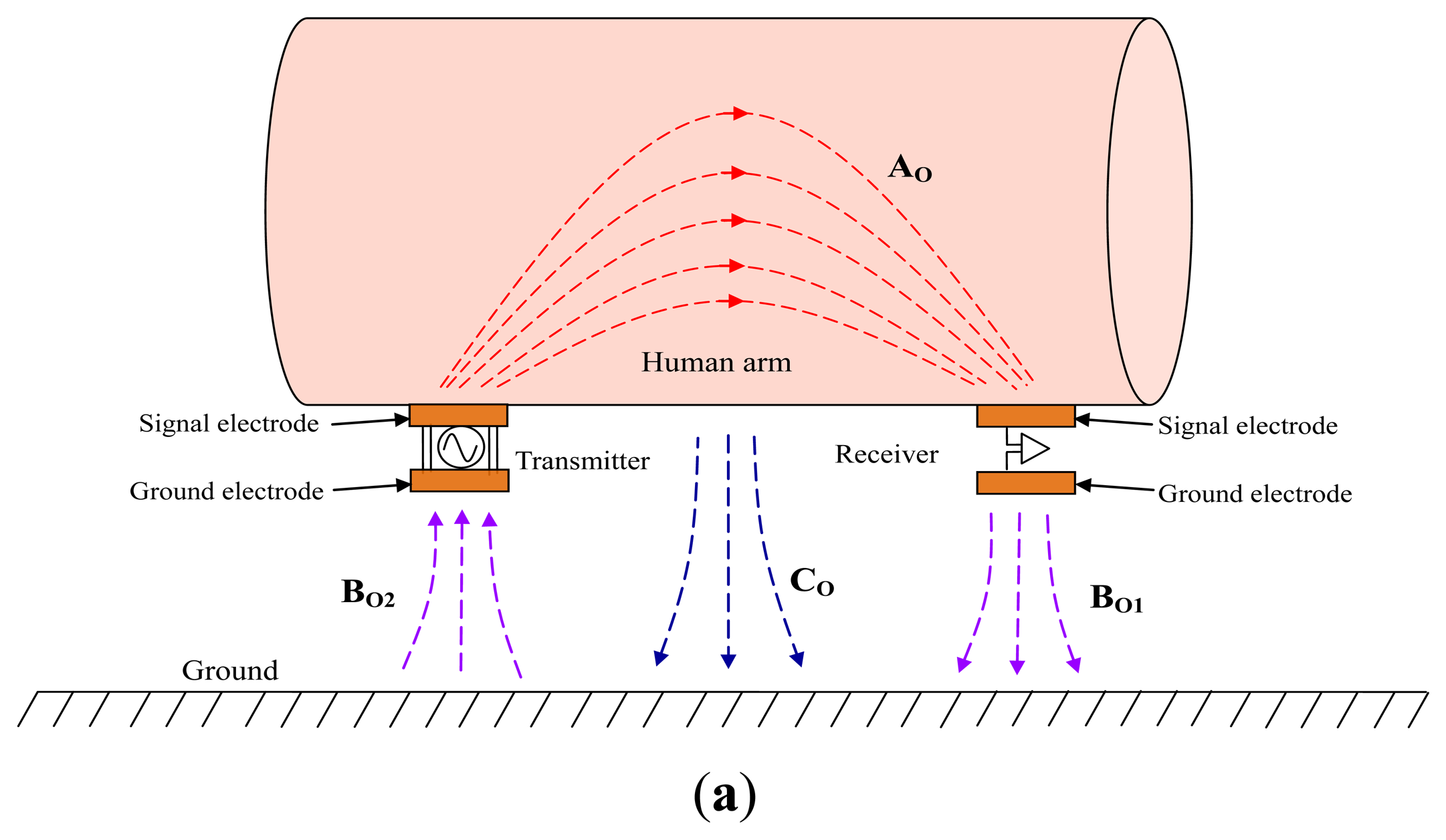
Firstly, the difference between the on-body IBC based on capacitive coupling and the implant IBC based on capacitive coupling is analyzed. In the on-body IBC based on capacitive coupling, as shown in Figure 2a, only two signal electrodes are attached on the human body (e.g., human arm), while an electric field AO forms between them though the body. Meanwhile, both the transmitting ground electrode and the receiving ground electrode remain floating, which results in an electric field BO2 between the ground electrode of transmitter and ground as well as an electric field BO1 between the ground electrode of receiver and the ground. Finally, the return path of signal is established by the electric field of BO1, the ground and the electric field of BO2, thereby signal transmission between the transmitter and the receiver can be achieved. On the other hand, there is also an electric field CO between the body and the ground because of the body potential, which affects the signal transmission of IBC to some extent [1].
In the implant IBC based on capacitive coupling, both the transmitter and receiver are implanted into human body, as shown in Figure 2b. In our investigation, each implant capacitive electrode contains a signal electrode made of a metal stick and a ground electrode made of a metal cylindrical casing. Meanwhile, the signal electrode contacts with the human tissue directly, and the ground electrode is insulated from the human tissue as well as the signal electrode by using an insulating shell, which avoids the body shorting the signal between the signal electrode and the ground electrode. Moreover, compared with the coupling between the signal electrode and the ground electrode, a comparatively bigger capacitive coupling between the two ground electrodes can also be achieved because of the comparatively bigger surface area of the two ground electrodes. Thereby, signal transmission between the transmitter and the receiver can be achieved with low attenuation.
In the implant IBC based on capacitive coupling shown in Figure 2b, there is an electric field AI between the signal electrode of transmitter and that of the receiver in human tissue, which is similar to electric field AO shown in Figure 2a. On the other hand, instead of locating outside the human body as shown in Figure 2a, the return path of the implant IBC based on capacitive coupling locates inside the human body, which is the capacitive coupling represented as the electric field BI between the two ground electrodes through the insulating shell and human tissue. Therefore, signal transmission between the implanted transmitter and the implanted receiver can be achieved through electric field AI and BI. Additionally, there is also a coupling between the body and the external ground through the electric field CI, as shown in Figure 2b. Considering the fact that both the signal electrode and ground electrode couple with the ground through the human tissue, thereby the electric field CI affects the coupling between the ground electrodes (electric field BI) and that between the signal electrodes (electric field AI) synchronously.
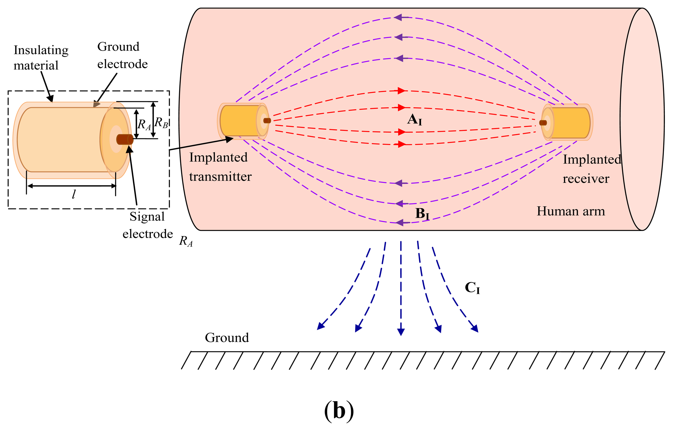
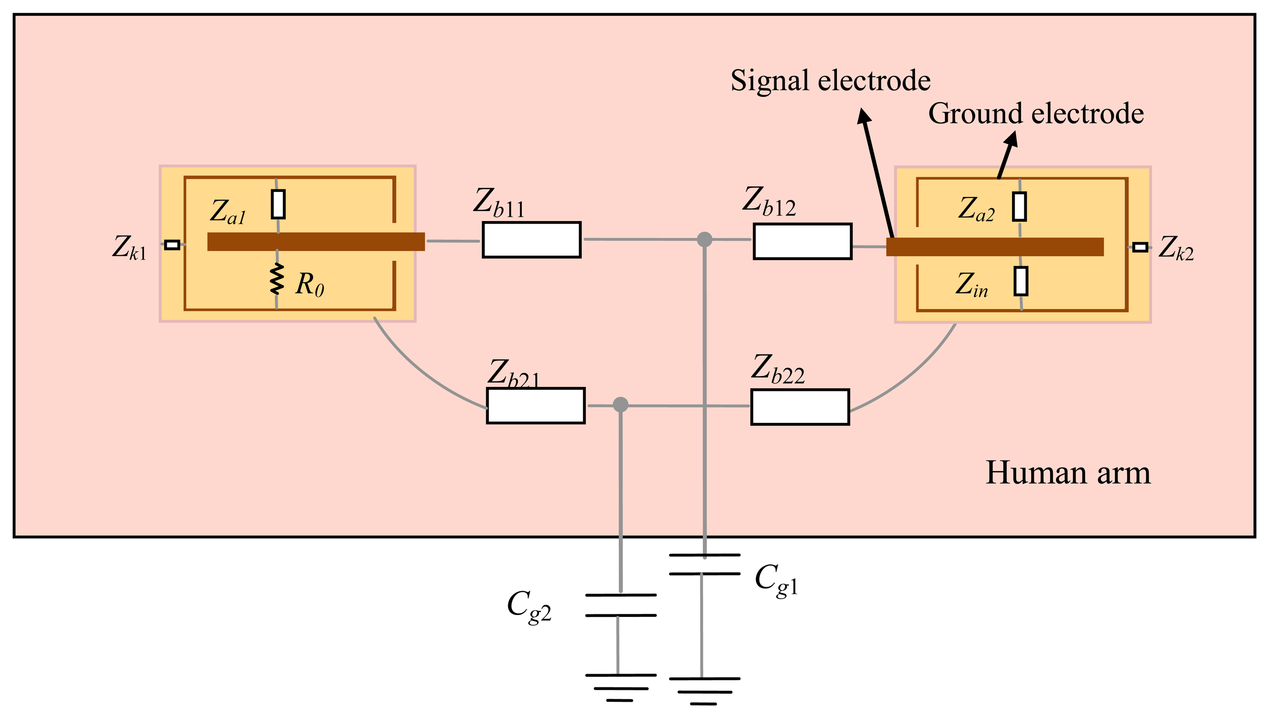
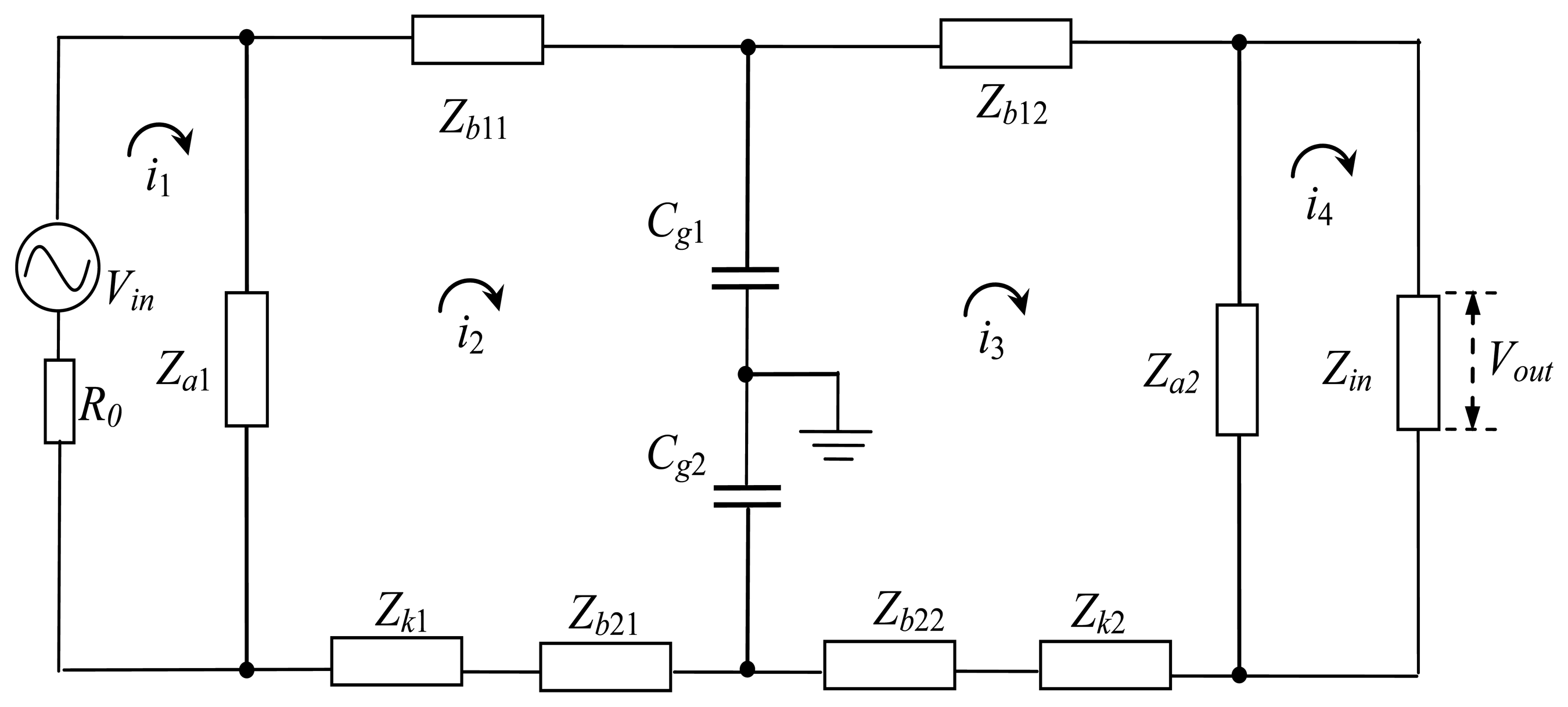
According to Figure 2b, the circuit model of the implant IBC can be obtained, as shown in Figure 3. The electrical model of each unit block can be represented as an impedance Z, which is equivalent to the parallel connection of corresponding capacitance C and resistance R [2,18], as shown in Equation (1):
In the circuit model of the transmitter, as shown in Figure 3, R0 represents the output resistance of the transmitter, Za1 is the impedance between the ground electrodes and the signal electrodes, and Zk1 represents the impedance of insulating shell between the ground electrode and the human tissue. On the other hand, Zb11 and Zb12 represent the transverse impedance between the two signal electrodes, and Zb21 and Zb22 represent the impedance between the two ground electrodes. Meanwhile, the coupling capacitances between the human body and the external ground are represented as Cg1 and Cg2, which affect the coupling paths between the signal electrodes (Zb11 and Zb12) and that between the ground electrodes (Zb21 and Zb22), respectively. Additionally, in the circuit model of the receiver, Zin represents the input impedance of the receiver, while the other parameters are similar to that of the transmitter.
The equivalent circuit of the circuit model in Figure 3 is shown in Figure 4, in which Vin represents the output voltage of the transmitter, and Vout represents the input voltage of the receiver.
2.2. Derivation of the Transfer Function
The transfer function of the implant IBC based on capacitive coupling can be derived by Kirchhoff voltage law (KVL) mesh equations [23,24], because the equivalent circuit of it is a linear system. In Figure 4, in (n = 1, 2, 3, 4) is the current of the corresponding mesh, then the following equation can be expressed as:
It is assumed that mesh impedance matrix Z contains the respective impedances in the circuit, which is a diagonal 4 × 4 square matrix as follows:
On the other hand, the column matrix of the voltage sources V and the matrix of the mesh currents I can be expressed as:
As a result, Equation (2) can be summarized as a matrix equation:
Furthermore, the mesh admittance matrix is determined by inverting the mesh impedance matrix as:
Therefore, the current i4 can be obtained by calculating the mesh current matrix I:
Then the output voltage of the implant IBC can be expressed as:
Finally, based on Equations (5) and (8), the attenuation of the signal transmission in the capacitive coupling IBC can be determined by:
3. Parameters
The following is the discussion with respect to the parameters of the deduced transfer function.
3.1. Transverse Impedance (Zb)
Due to the fact that the human body generally consists of five layers (skin, fat, muscle, cortical bone, and bone marrow), Zb can be expressed as the parallel connection of the impedances corresponding to the different layers [25]:
3.2. Impedance of Insulating Shell (Zk1 and Zk2)
Zk1 and Zk2, which are the impedances of insulating shell between the ground electrode and the human tissue, can be obtained by Equation (1) using Ck1, Ck2 and Rk1, Rk2. The capacitances of Ck1 and Ck2 represent the capacitances between two coaxial cylinders, which are expressed by Equation (11):
3.3. Capacitance Between the Human Body and the External Ground (Cg1, Cg2)
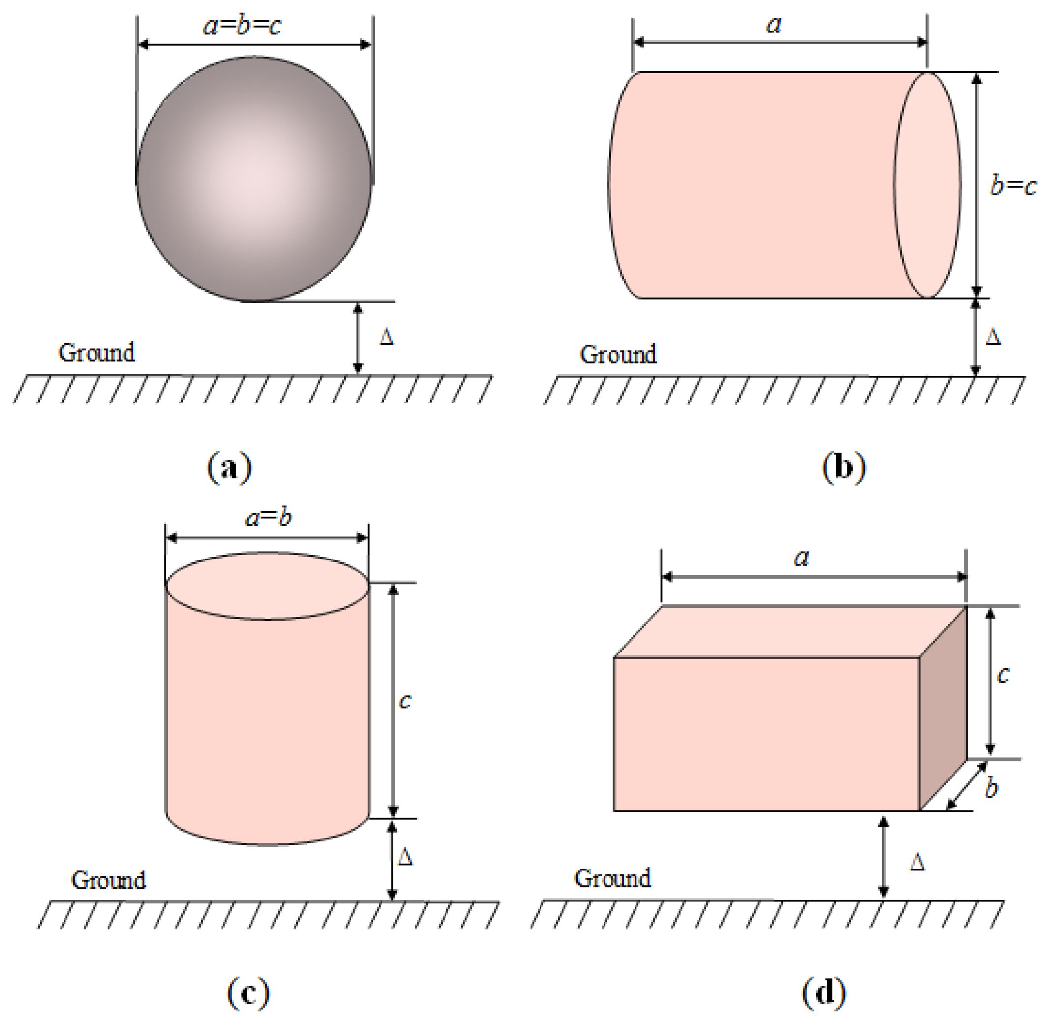
It is assumed that if a person stands in an open space, and the human body is approximated as a conductive cylinder or sphere [1], then the capacitance (Cg) between the human body and the external ground can be represented as [27]:
As a result, the capacitance between the object and the ground of infinity C∞, can be assumed as a sphere with diameter le in free space, which is calculated as follows [27]:
In our investigation, the arm attached with the electrodes is abstracted as a cylinder, of which the diameter is d and the height is l. According to Equations (13) and (14), C∞ between the arm and the ground of infinity can be calculated by:
On the other hand, the capacitance of CP can be approximated as [27]:
4. Experiments and Discussion
In order to verify the validity of the proposed models and parameters, the measurements of implant IBC and the mathematical simulations based on the proposed transfer function were carried out. Moreover, the characteristics of the implant IBC based on capacitive coupling were also analyzed.
4.1. Experiment Setup
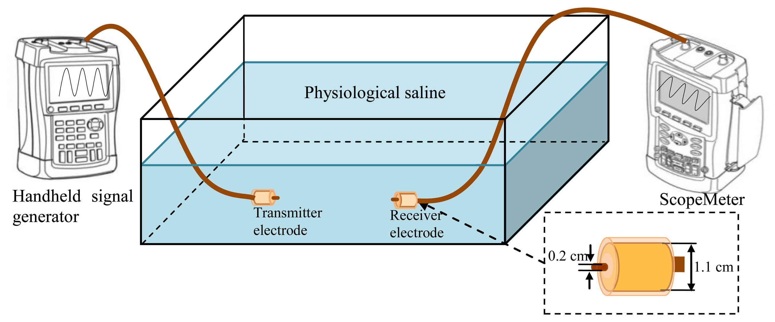
In our investigation, the experiment setup of the implant IBC based on capacitive coupling was composed of a handheld signal generator, a ScopeMeter, a pair of implantable capacitive coupling electrodes and a rectangle tank, as shown in Figure 6. The handheld signal generator (DSO8060, R0 = 50 Ω) was used to provide the output signal at the transmitter terminal, and the ScopeMeter (Fluke 196C, Rin = 1 MΩ and Cin = 15 pF) was used to measure the signal at the receiving terminal. Both the handheld signal generator and the ScopeMeter were powered by battery for decreasing the influence of the external ground and simulating the actual application of implant IBC. Additionally, all the measurements were carried out at room temperature (298.15 K).
A rectangle tank with the size of 45 × 35 × 20 cm was used for simulating the human body, as shown in Figure 6. The tank was filled with physiological saline [28], which is assumed to be isotropic, as well as has the conductivity (σ) of 1.75 S/m and the relative permittivity (εr) of 80.4, as shown in Table 1. Therefore, the resistance and capacitance of the transmission path can be obtained by R = L/σA and C = εrε0A/L, where A is the cross-section area of the transmission path, and L is the length of the transmission path. C∞ of the measurement tank can be calculated by Equation (14), while its CP can be calculated according to Equation (16), which is equal to:
In our experiment setup, the ground electrode of the capacitive coupling electrodes is cylindrical casing and packed with insulating shell (σ = 1 × 10⁻¹⁴, εr = 3). The radius RA of the ground electrode is 0.55 cm, and the radius RB of the insulating shell is 0.6 cm. Meanwhile, the signal electrode with the radius of 0.1 cm, is contacted with the physiological saline directly, as shown in Figure 6.
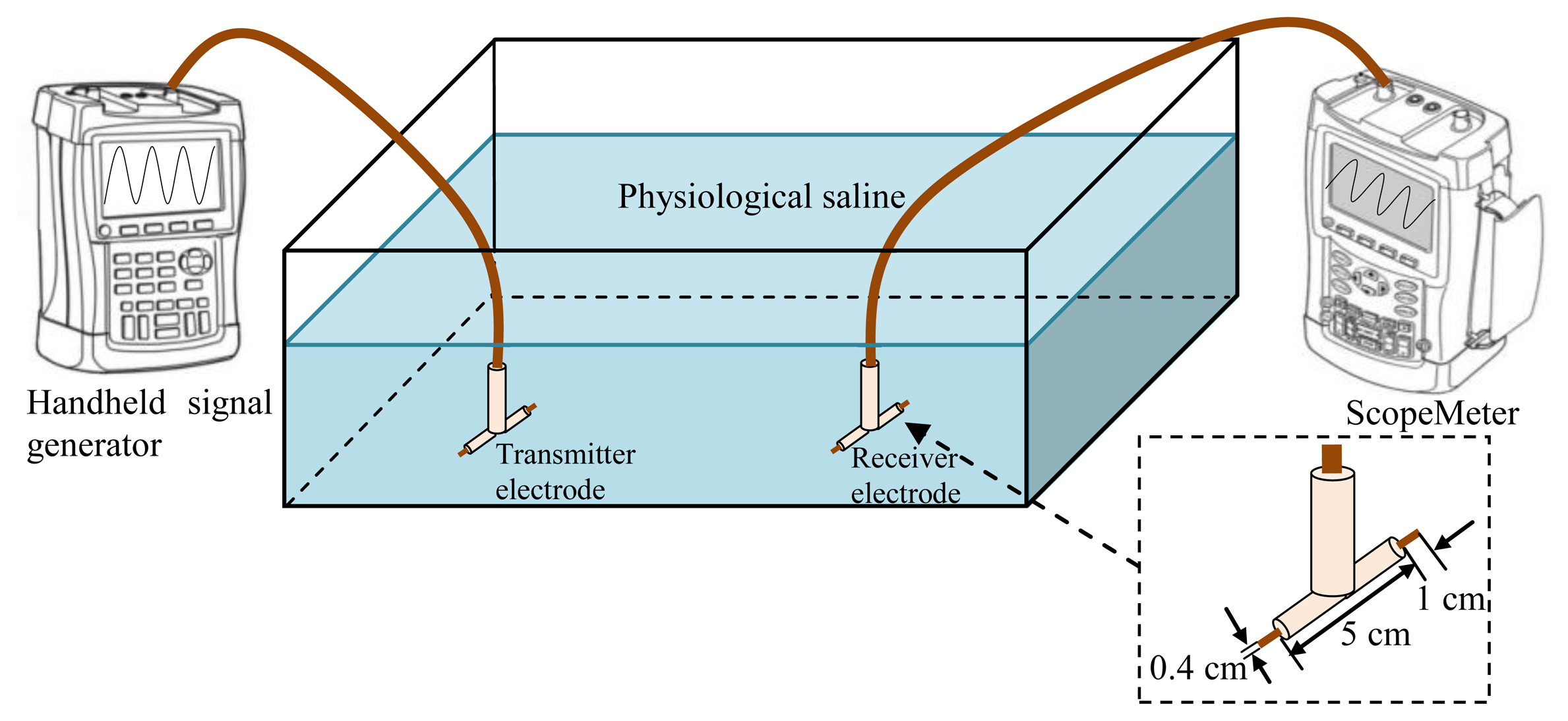
Moreover, in order to verify the advantages of implant IBC based on capacitive coupling compared with the implant IBC based on galvanic coupling, the electrodes of the implant IBC based on galvanic coupling were also developed, which had two cylindrical copper endings (length 1 cm and diameter 4 mm) and the distance between them was 5 cm [5]. Figure 7 shows the experiment setup of the implant IBC based on galvanic coupling.
4.2. Comparison of Implant IBC Based on Two Coupling Methods
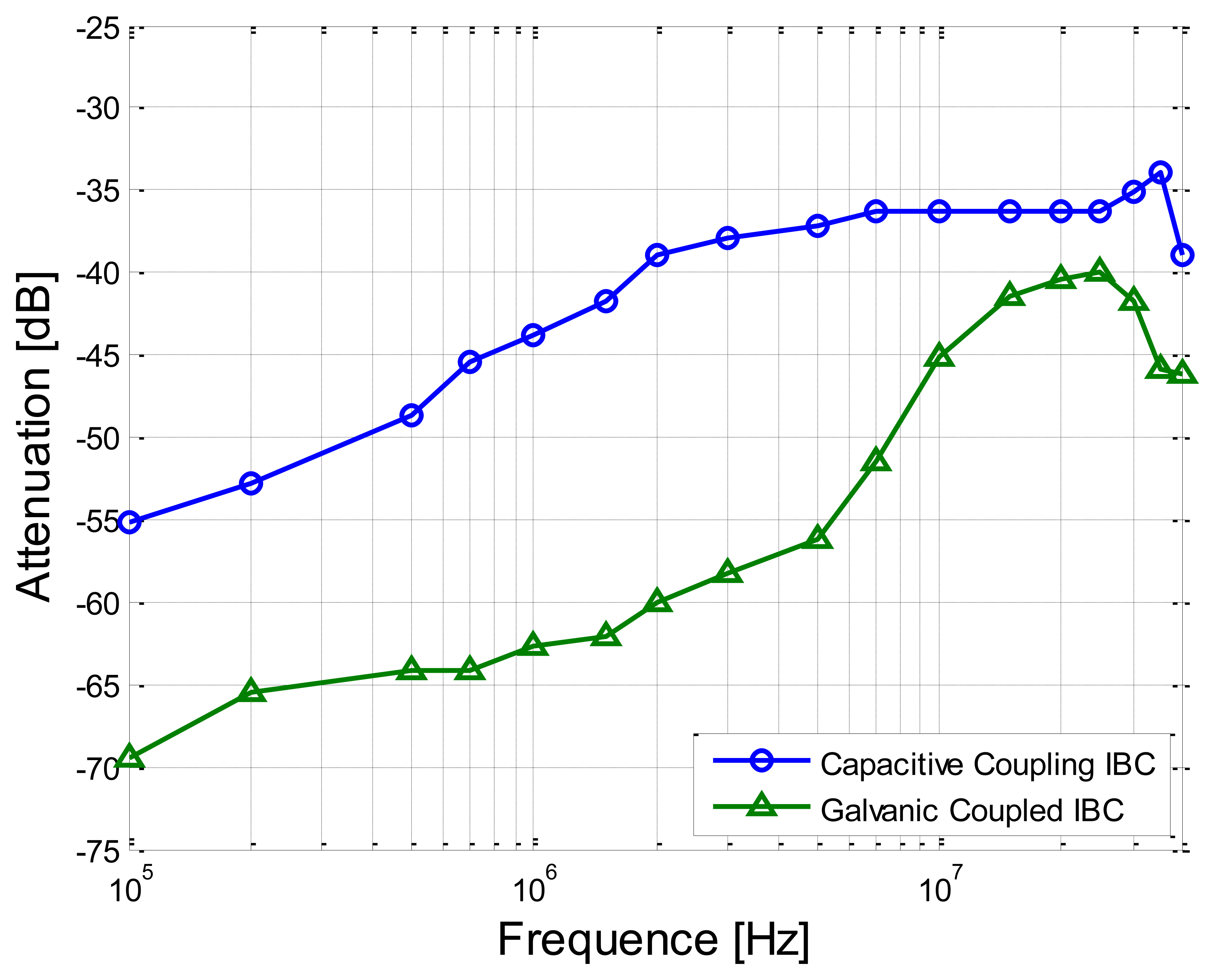
In this experiment, the separation distance between the transmitter electrode and the receiver electrode was set as 30 cm. Meanwhile, the sine wave signals with the amplitude of 4 V (peak-to-peak value) were applied on the transmitter electrodes. On the other hand, the signal frequency range of 100 kHz–40 MHz was chosen in our measurement, due to the fact that the power spectrum of the electrical signals produced by the biological processes mainly covers the low frequency range (less than 100 kHz) [5] and there is also the limitation of the circuit model in the high-frequency range [10].
Figure 8 shows the measurement results with respect to the frequency-dependent characteristics of the proposed method and the implant IBC based on galvanic coupling. We can find from Figure 8 that the attenuation of the proposed method is significantly lower (on average by 13.13 dB) than that of the implant IBC based on galvanic coupling. Meanwhile, both the two signal attenuation curves decrease gradually with the increasing of the signal frequency from 100 kHz to 2 MHz. However, the result of the IBC based on the galvanic coupling has comparatively bigger variation (the maximum deviation is up to 29.54 dB) in the frequency range of 2 MHz–40 MHz, while the result of the proposed method has comparatively smaller variation (the maximum deviation is only 3.90 dB) in the same frequency range. The above phenomenon can be explained that there is comparatively bigger coupling between the signal electrode and the ground electrode of transmitter in the IBC based on the galvanic coupling, thereby only lower signal energy can reach the receiver electrodes. On the contrary, in the proposed method, the mentioned coupling is weakened by using the insulating shell, thereby more signal energy can reach the receiver electrodes, which results in lower signal attenuation.
4.3. Verification of the Transfer Function
In order to verify the validity and the accuracy of the transfer function, both the measurements and the corresponding simulations with respect to the frequency-dependent characteristics of the proposed method were carried out under the conditions of the different signal transmission distances and heights.
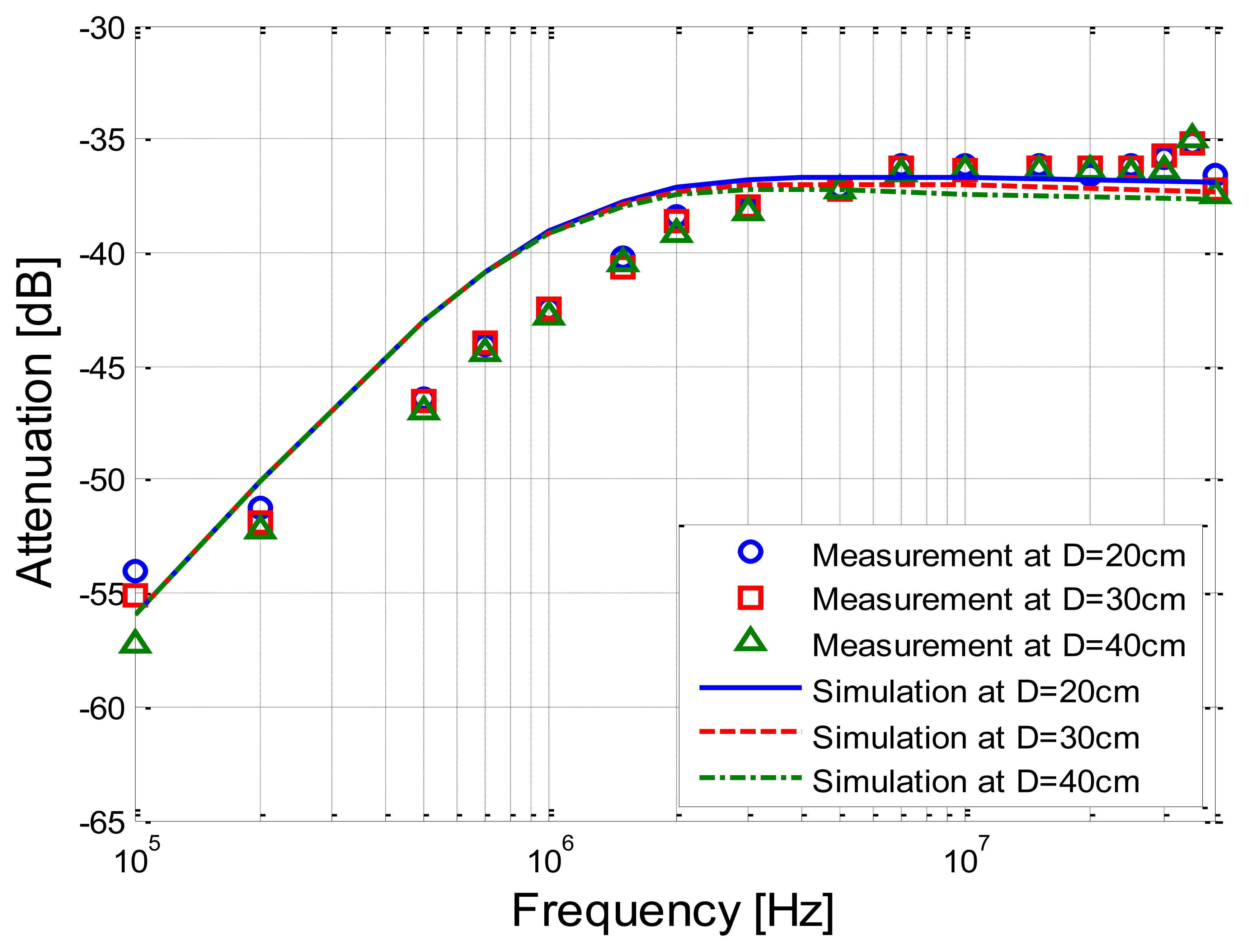
Figure 9 shows the measurements and simulation results corresponding to the signal transmission distances of 20 cm, 30 cm and 40 cm, respectively. It can be seen from Figure 9 that the simulation results based on the developed transfer function basically coincide with the corresponding measurement results, while the deviations between the simulation and the measurement are limited within 3.93 dB. Meanwhile, both the simulation results and the measurement results decrease as the signal frequency increases from 100 kHz to 2 MHz, and have little variation within the frequency range of 2 MHz–40 MHz.
On the other hand, when the signal transmission distance increases from 20 cm to 40 cm, both the signal attenuations of the two results have little variation. For instance, an increase of 10 cm of the signal transmission distance only leads to an extra attenuation of 0.25 dB on average according to the measurement results. Similarly, the extra attenuation of the corresponding simulation is 0.14 dB on average, which indicates that both of them basically are not sensitive to the signal transmission distances.
Moreover, under the condition that the height between the tank and the ground was set as 1 cm, 50 cm and 80 cm, respectively, while the signal transmission distance was set as 20 cm, the implant IBC experiments as well as the corresponding simulations based on the transfer function were carried out. Figure 10 shows the comparison between the measurement results and simulation results corresponding to the different heights.
It can be observed from Figure 10 that the mathematical simulation results also basically coincide with the corresponding measurement results. Meanwhile, the attenuation of the measurement results corresponding to the height of 50 cm is 6.00 dB less than that of the height of 1 cm on average, while a similar decrease (5.27 dB) can also be found in the simulation results. In addition, the curve of the measurement corresponding to the height of 80 cm overlaps with that of the height of 50 cm, and the corresponding variations are limited in 0.28 dB. Meanwhile, the similar phenomenon can be found in simulation results, and the variations are limited within 0.12 dB, which indicates that both the measurement and the simulation results remain basically unchanged as the height increases from 50 cm to 80 cm.
4.4. Characteristics of the Implant IBC Based on the Capacitive Coupling
In order to determine the characteristics of the proposed method, the corresponding simulations of the proposed method were carried out under the conditions of the different frequencies, signal transmission distances and heights based on the transfer function which has been verified. In our simulation, it is assumed that the human body is in static state at room temperature (298.15 K), which means that the capacitance to the ground keeps unchanged, and the influence of temperature variation is ignored [29,30].
4.4.1. Characteristics of Frequency and Distance
In this simulation, we assumed that the implantable capacitive coupling electrodes were embedded in the arm, of which the diameter was 10 cm. The attenuation curves corresponding to the different distances (20, 30 and 40 cm) are shown in Figure 11, in which the distance between the arm and the ground is 50 cm and the capacitance Cg1 between the arm and the ground is equal to 7.99 pF.
It can be seen from Figure 11 that the attenuation becomes lower when the frequency increases from 100 kHz to 3 MHz, and it remains relatively stable when the frequency increases from 3 MHz to 10 MHz, which is similar to the results shown in Figure 9. On the other hand, the attenuation has a slight increasing when the frequency is higher than 10 MHz. Therefore, the comparatively lower signal attenuation can be achieved by using the proposed method in the case that the signal frequency range is within the range of 3 MHz–10 MHz. What's more, according to the results shown in Figure 11, the signal transmission distance has comparatively less effect on the signal attenuation. For instance, the mean deviation is only 0.06 dB in the frequency range of 100 kHz–40 MHz when the distance is increased by 10 cm. This phenomenon can be interpreted as that the impedance of the human body path (Zb) is much smaller than the other impedances of the return path (such as Zg1 and Zk1). As a result, the signal attenuation changes little with the increase of the transmission distance, which caused the increase of Zb.
4.4.2. Characteristics of Height
In our simulations under the conditions of different heights to the ground, the distance of transmission was set as 20 cm, while the simulation frequencies were set as 3 MHz and 10MHz, which were corresponding to the cases that Rb11 = 60.9 Ω, Cb11 = 116 pF as well as Rb11 = 54 Ω, Cb11 = 33 pF, respectively. The corresponding simulation results are shown in Figure 12. According to Figure 12, the signal attenuation basically decreases with the increase of the height, in which the decrease of attenuation corresponding to 3 MHz is 1.39 dB in the case that the height increases from 1 cm to 30 cm, while the value corresponding to 10 MHz is 1.43 dB.
This phenomenon can be interpreted as that the capacitive coupling between the arm and the external ground becomes smaller as the height of the arm increases. For example, Cg1 is equal to 22.83 pF when the height is 1 cm, while it is equal to 9.07 pF when the height is increased to 30 cm. Therefore, when the height decreases to some extent (such as less than 10 cm), the comparatively higher signal power is lost to the external ground through the capacitance betwe nen the arm and the ground, which leads to the comparatively bigger increase of signal attenuation. On the other hand, the attenuation becomes basically stable when the height is higher than 30 cm. For instance, the difference between the signal attenuation corresponding to 30 cm and the signal attenuation corresponding to 100 cm is only 0.12 dB when the frequency is 10 MHz. A similar phenomenon can be found in the results corresponding to 3 MHz. The main reason for this phenomenon can be interpreted as that the additional capacitance to the ground (CP_arm) decreases gradually with the increase of the height and finally reduces to zero, which is expressed as Equation (17).
5. Conclusions
In this paper, we propose an implant intra-body communication (IBC) method based on capacitive coupling, and investigate its transfer function and characteristics. Firstly, we derived the transfer function of the implant IBC based on capacitive coupling. Secondly, the corresponding parameters used in the transfer function were discussed. Finally, both the measurements of the proposed method and the corresponding simulations based on the transfer function were carried out under different conditions.
From the measurement and simulation results, we find that: (1) The simulation results based on the developed transfer function basically coincide with the measurements; (2) Compared with the implant IBC based on galvanic coupling, the proposed method has comparatively lower signal attenuation and basically stable frequency response within the frequency range of 2 MHz–40 MHz; (3) In the proposed method, the signal transmission distance almost has no influence on the signal attenuation; (4) The signal attenuation of the proposed method decreases with the increase of the height between body and the ground, and it becomes basically stable when the height is higher than a certain value, such as 30 cm. The above conclusions indicate that the proposed method of the implant IBC based on capacitive coupling has the advantages of low signal attenuation, insensitivity to signal transmission distance and so on. It will help to achieve an implant communication method for e-healthcare or u-healthcare with the characteristics of low power consumption and high transmission quality, etc.
Acknowledgments
The work was supported by the National Natural Science Foundation of China (60801050), the Excellent Talent Fund of Beijing, China (2011), Excellent Young Scholars Research Fund of Beijing Institute of Technology, China (2012).
Conflicts of Interest
The authors declare no conflict of interest.
References
- Zimmerman, T.G. Personal Area Networks (PAN): Near-Field Intra-Body Communication. Ms.C. Thesis, Massachusetts Institute of Technology, Boston, MA, USA, 1995. [Google Scholar]
- Cho, N.; Yoo, J.; Song, S.-J.; Lee, J.; Jeon, S.; Yoo, H.-J. The human body characteristics as a signal transmission medium for intrabody communication. IEEE Trans. Microw Theory Tech. 2007, 55, 1080–1085. [Google Scholar]
- Callejon, M.; Roa, L.; Reina-Tosina, L.; Naranjo, D. Study of attenuation and dispersion through the skin in intra-body communications systems. IEEE Trans. Inform. Technol. Biomed. 2012, 16, 159–165. [Google Scholar]
- Xu, R.; Zhu, H.; Yuan, J. Circuit-Coupled FEM Analysis of the Electrical-Field Type Intra-Body Communication Channel. Proceedings of the IEEE Biomedical Circuits and Systems Conference (BioCAS), Beijing, China, 26–28 November 2009; pp. 221–224.
- Wegmueller, M.S. Intra-Body Communication for Biomedical Sensor Networks. Ph.D. Thesis, ETH Zurich, Zurich, Switzerland, 2007. [Google Scholar]
- Wegmueller, M.S.; Huclova, S.; Froehlich, J.; Oberle, M.; Felber, N.; Kuster, N.; Fichtner, W. Galvanic coupling enabling wireless implant communications. IEEE Trans. Instrum. Meas. 2009, 58, 2618–2625. [Google Scholar]
- Sasamori, T.; Takahashi, M.; Uno, T. Transmission mechanism of wearable device for on-body wireless communications. IEEE Trans. Anten. Propag. 2009, 57, 936–942. [Google Scholar]
- Lin, Y.T.; Lin, Y.S.; Chen, C.H.; Chen, H.C.; Yang, Y.C.; Lu, S.S. A 0.5-V biomedical system-on-a-chip for intrabody communication system. IEEE Trans. Ind. Electron. 2011, 58, 690–699. [Google Scholar]
- Shinagawa, M.; Fukumoto, M.; Ochiai, K.; Kyuragi, H. A near-field sensing transceiver for intrabody communication based on the electrooptic effect. IEEE Trans. Instrum. Meas. 2004, 53, 1533–1538. [Google Scholar]
- Sasaki, A.; Shinagawa, M.; Ochiai, K. Principles and demonstration of intrabody communication with a sensitive electrooptic sensor. IEEE Trans. Instrum. Meas. 2009, 58, 457–466. [Google Scholar]
- Seyedi, M.; Kibret, B.; Lai, D.T.H.; Faulkner, M. A survey on intrabody communications for body area network applications. IEEE Trans. Biomed. Eng. 2013, 60, 2067–2079. [Google Scholar]
- Santagati, G.E.; Melodia, T.; Galluccio, L.; Palazzo, S. Distributed MAC and Rate Adaptation for Ultrasonically Networked Implantable Sensors. Proceedings of the IEEE Conference on Sensor, Mesh and Ad Hoc Communications and Networks (SECON), New Orleans, LA, USA, 24–27 June 2013; pp. 104–112.
- Zhen, B.; Li, H.B.; Kohno, R. Networking issues in medical implant communications. Int. J. Multimedia Ubiquit. Eng. 2009, 4, 23–38. [Google Scholar]
- Estudillo, M.A.; Naranjo, D.; Roa, L.M.; Reina-Tosina, J. Intrabody Communications (IBC) as an Alternative Proposal for Biomedical Wearable Systems. In Handbook of Research on Developments in E-Health and Telemedicine: Technological and Social Perspectives; Cruz-Cunha, M.M., Ed.; IGI Global: Hershey, PA, USA, 2009; pp. 1–28. [Google Scholar]
- Wegmueller, M.S.; Hediger, M.; Kaufmann, T.; Oberle, M.; Kuster, N.; Fichtner, W. Investigation on Coupling Strategies for Wireless Implant Communications. Proceedings of the Instrumentation and Measurement Technology Conference, Warsaw, Poland, 1–3 May 2007; pp. 1–4.
- Chen, X.M.; Mak, P.U.; Pun, S.H.; Gao, Y.M.; Lam, C.T.; Vai, M.I.; Du, M. Study of channel characteristics for galvanic-type intra-body communication based on a transfer function from a quasi-static field model. Sensors 2012, 12, 16433–16450. [Google Scholar]
- Callejon, M.; Naranjo, D.; Reina-Tosina, J.; Roa, L. Distributed circuit modeling of galvanic and capacitive coupling for intrabody communication. IEEE Trans. Biomed. Eng. 2012, 59, 3263–3269. [Google Scholar]
- Xu, R.; Zhu, H.; Yuan, J. Electric-field intrabody communication channel modeling with finite-element method. IEEE Trans. Biomed. Eng. 2011, 58, 705–712. [Google Scholar]
- Hachisuka, K.; Terauchi, Y.; Kishi, Y.; Sasaki, K.; Hirota, T.; Hosaka, H.; Ito, K. Simplified circuit modeling and fabrication of intra body communication devices. Sens. Actuat. A Phys. 2006, 130/131, 322–330. [Google Scholar]
- Song, Y.; Zhang, K.; Hao, Q.; Rolland, P. Modeling and characterization of the electrostatic coupling intra-body communication based on Mach-Zehnder electro-optical modulation. Opt. Express 2012, 20, 13488–13500. [Google Scholar]
- Song, Y.; Zhang, K.; Hao, Q.; Wang, J.; Jin, X.; Sun, H. Signal transmission in a human body medium-based body sensor network using a Mach-Zehnder electro-optical sensor. Sensors 2012, 12, 16557–16570. [Google Scholar]
- Lucev, Z.; Krois, I.; Cifrek, M. A Capacitive Intrabody Communication Channel from 100 kHz to 100 MHz. Proceedings of the IEEE Instrumentation and Measurement Technology, Beijing, China, 10–12 May 2011; pp. 1–4.
- Gottling, J.G. Node and mesh analysis by inspection. IEEE Trans. Educ. 1995, 38, 312–316. [Google Scholar]
- Karris, S.T. Circuit Analysis I: With MATLAB Applications; Orchard Publications: Fremont, CA, USA, 2003; pp. 8–20. [Google Scholar]
- Song, Y.; Hao, Q.; Zhang, K.; Wang, M.; Chu, Y.F.; Kang, B.Z. The simulation method of the galvanic coupling intrabody communication with different signal transmission paths. IEEE Trans. Instrum. Meas. 2011, 60, 1257–1266. [Google Scholar]
- Gabriely, S.; Lau, R.W.; Gabriel, C. The dielectric properties of biological tissues: III. Parametric models for the dielectric spectrum of tissues. Phys. Med. Biol. 1996, 41, 2271–2293. [Google Scholar]
- Maruvada, P.S.; Hylten-Cavallius, N. Capacitance calculations for some basic high voltage electrode configurations. IEEE Trans. Power Appar. Syst. 1975, 94, 1708–1713. [Google Scholar]
- Gao, Y.M.; Pun, S.H.; Du, M.; Vai, M.I.; Mak, P.U. Quasi-static Field Modeling and Validation for Intra-body Communication. Proceedings of the Bioinformatics and Biomedical Engineering (ICBBE), Beijing, China, 11–13 June 2009; pp. 1–4.
- Lay-Ekuakille, A.; Vendramin, G.; Trotta, A. Design of an Energy Harvesting Conditioning Unit for Hearing Aids. Proceedings of the 30th Annual International Conference of the IEEE Engineering in Medicine and Biology Society, Vancouver, BC, Canada, 20–25 August 2008; pp. 2310–2313.
- Ben Amor, N.; Kanoun, O.; Lay-Ekuakille, A.; Vendramin, G.; Specchia, G.; Trotta, A. Energy Harvesting from Human Body Movements for Biomedical Autonomous Systems. Proceedings of the 7th IEEE Conference on Sensors, Lecce, Italy, 26–29 October 2008; pp. 678–680.


| Materials | Physiological Saline | Insulating Shell | ||
|---|---|---|---|---|
| Parameters | σ (S/m) | εr | σ (S/m) | εr |
| Values | 1.75 | 80.4 | 1 × 10⁻¹⁴ | 3 |
© 2014 by the authors; licensee MDPI, Basel, Switzerland. This article is an open access article distributed under the terms and conditions of the Creative Commons Attribution license (http://creativecommons.org/licenses/by/3.0/).
Share and Cite
Zhang, K.; Hao, Q.; Song, Y.; Wang, J.; Huang, R.; Liu, Y. Modeling and Characterization of the Implant Intra-Body Communication Based on Capacitive Coupling Using a Transfer Function Method. Sensors 2014, 14, 1740-1756. https://doi.org/10.3390/s140101740
Zhang K, Hao Q, Song Y, Wang J, Huang R, Liu Y. Modeling and Characterization of the Implant Intra-Body Communication Based on Capacitive Coupling Using a Transfer Function Method. Sensors. 2014; 14(1):1740-1756. https://doi.org/10.3390/s140101740
Chicago/Turabian StyleZhang, Kai, Qun Hao, Yong Song, Jingwen Wang, Ruobing Huang, and Yue Liu. 2014. "Modeling and Characterization of the Implant Intra-Body Communication Based on Capacitive Coupling Using a Transfer Function Method" Sensors 14, no. 1: 1740-1756. https://doi.org/10.3390/s140101740