Stretchable and Flexible High-Strain Sensors Made Using Carbon Nanotubes and Graphite Films on Natural Rubber

Abstract
: Conventional metallic strain sensors are flexible, but they can sustain maximum strains of only ∼5%, so there is a need for sensors that can bear high strains for multifunctional applications. In this study, we report stretchable and flexible high-strain sensors that consist of entangled and randomly distributed multiwall carbon nanotubes or graphite flakes on a natural rubber substrate. Carbon nanotubes/graphite flakes were sandwiched in natural rubber to produce these high-strain sensors. Using field emission scanning electron microscopy, the morphology of the films for both the carbon nanotube and graphite sensors were assessed under different strain conditions (0% and 400% strain). As the strain was increased, the films fractured, resulting in an increase in the electrical resistance of the sensor; this change was reversible. Strains of up to 246% (graphite sensor) and 620% (carbon nanotube sensor) were measured; these values are respectively ∼50 and ∼120 times greater than those of conventional metallic strain sensors.1. Introduction
Piezoresistive materials are materials in which the electrical resistance is a function of the internal strain [1]. Piezoresistive strain sensors can be grouped into two types; flexible, and flexible and stretchable sensors. Metallic strain sensors and polymer composite-based strain sensors are examples of flexible and flexible and stretchable strain sensors, respectively. Metallic strain sensors are widely used; the maximum strain measurable with these sensors is 5% [2]. There are a number of different types of polymer-based strain sensors [3]. They are typically made using conductive fillers such as single-walled carbon nanotubes, multiwalled carbon nanotubes (MWCNTs), carbon black, graphite in a polymer matrix, or film composites [4–6]. Polymer composite strain sensors offer a maximum measurable strain that is greater than that of metallic strain sensors. Sensors that can measure high strains typically show lower sensitivity, and highly sensitive sensors typically offer small maximum measurable strains [7,8]. Yamada et al. introduced a different method for the fabrication of strain sensors using aligned carbon nanotubes. These sensors could measure strains of up to 280% (sensitivity 0.82–0.06); the authors reported that maximum strains of only ∼5% were measurable using randomly aligned single wall carbon nanotubes [9]. Shin et al. reported a maximum measurable strain of up to 300% with a sensitivity 0.34–1.07 using a MWCNT forest [10]. Although these sensors' measurable strains were high, the sensitivity values were lower than those of commercially available metallic strain sensors, whose sensitivity typically has a value of 2.
Here, we report two types of strain sensors fabricated by sandwiching conductive films between natural rubber (NR) layers, where the conductive layers consisted of randomly distributed, entangled MWCNTs, or graphite flakes. These two types of sensors could measure high strains of up to 620% (MWCNT sensor) and 246% (graphite sensor), with high sensitivities of 5–43 and 12–346, respectively. The effect of the sample dimensions (width, length) on the sensitivity and growth rate of the relative resistance was also investigated. Most of the reported sensors' response curves are nonlinear, so the application of a linear fit leads to large errors. To solve this problem, we introduce a linearization method to linearize the exponential response curves.
2. Experimental Section
2.1. Fabrication of Multiwalled Carbon Nanotube/Graphite Flake Strain Sensors
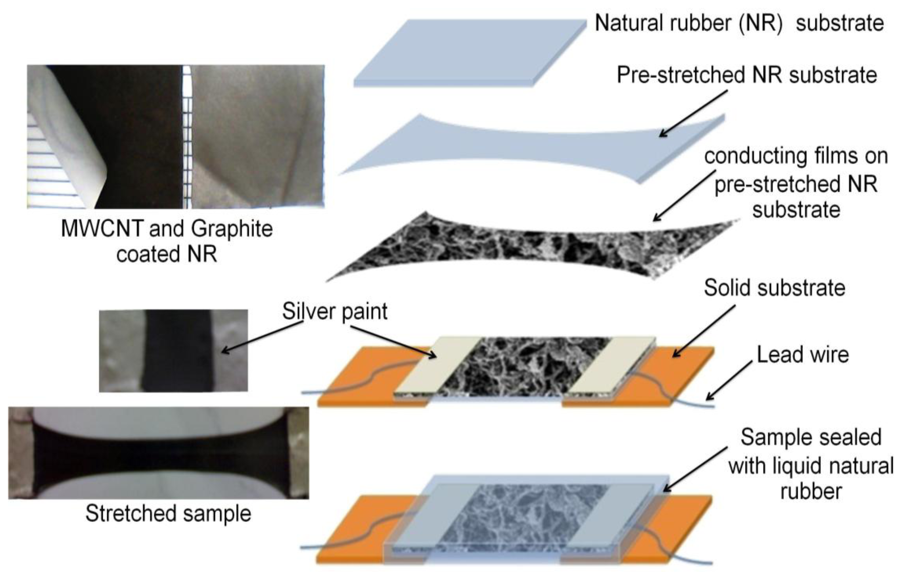
MWCNTs were synthesized using the CVD method [11], and graphite powder was purchased from Merck Chemicals Darmstadt, Germany. These two carbon allotropes were chosen as conducting powders. The NR substrate (thickness 0.080 mm) was pre-stretched, and MWCNT/graphite powder was coated on the substrate by gently rubbing the powder on the surface by hand (MWCNT: ∼0.109 mg/cm2, graphite: ∼0.16 mg/cm2, thickness: ∼10–20 μm). The graphite/MWCNTs adhered well to the NR surface because of the surface stickiness of NR; this stickness included a dispersive adhesion mechanism as well as a chemical adhesion mechanism (no adhesives were used). This MWCNT-coated NR sheet was then cut into several samples.
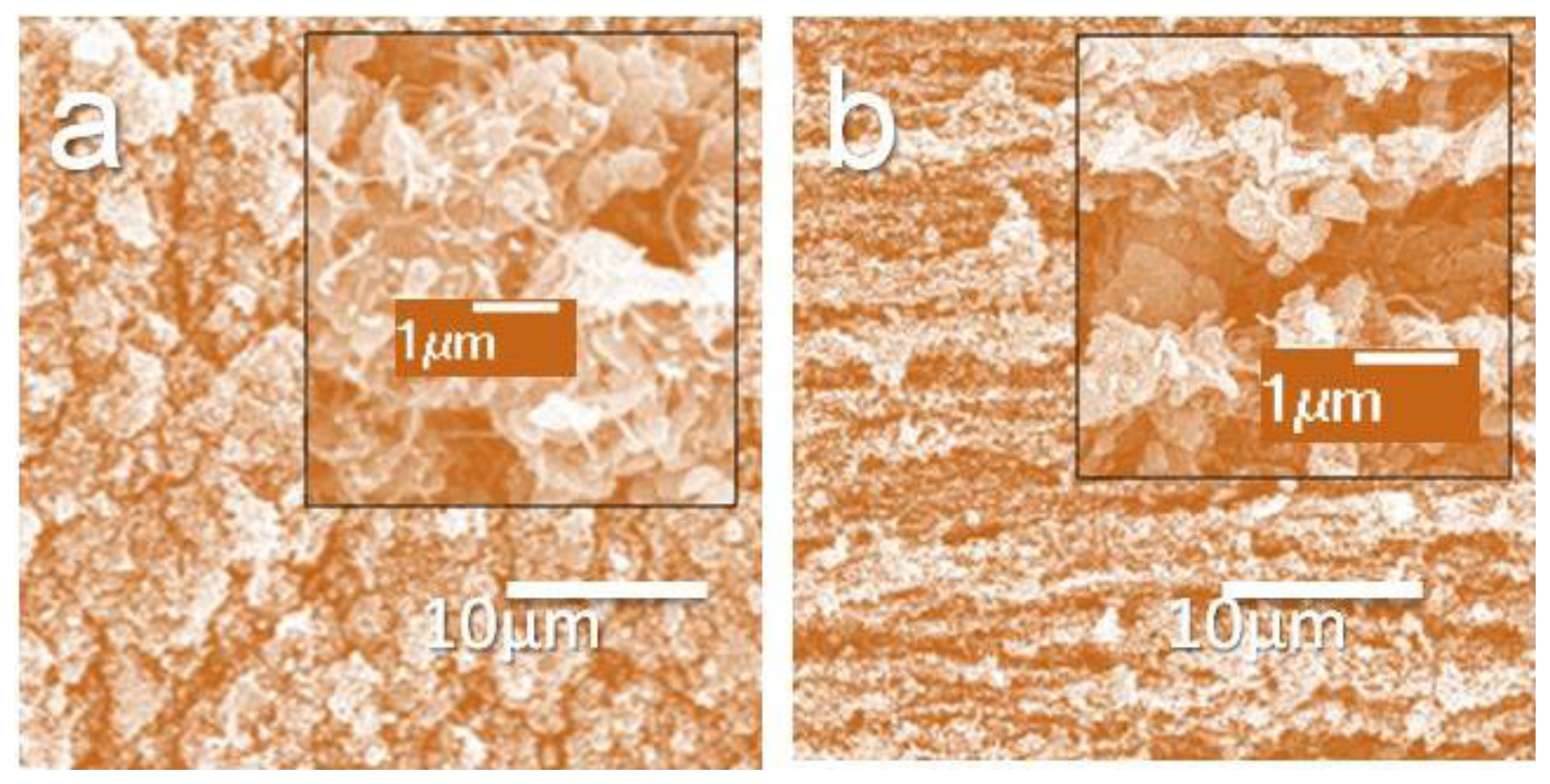
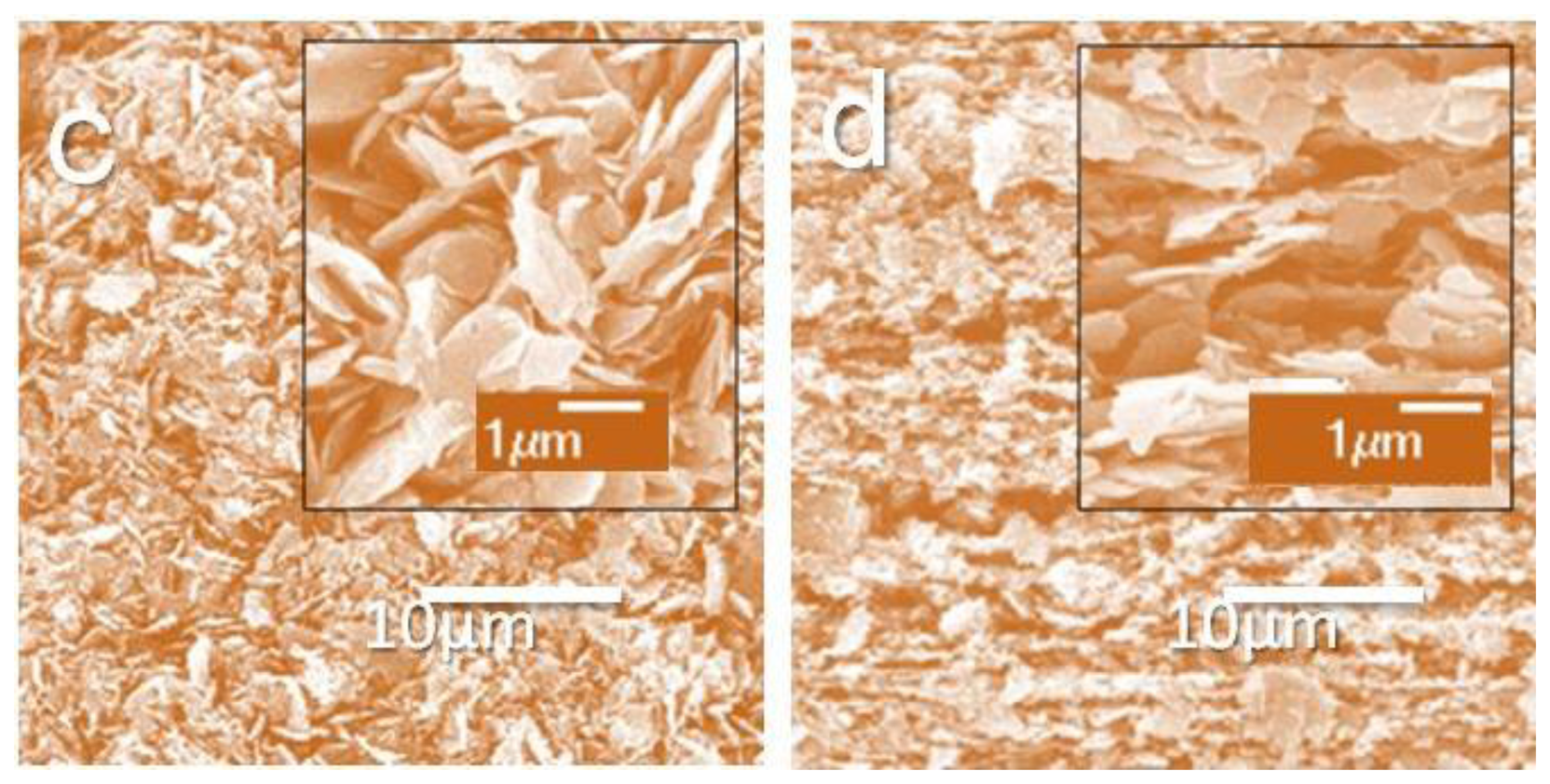
In the experiments, the two ends of the MWCNT-coated NR sample were strongly glued on two supporting acrylic pieces. Two electric wires were attached at the ends of the sample, using silver paint (on the strongly glued area of the sample). Because the silver paint was on the strongly glued, unstretchable area of the sample, no cracking of the silver paint occurred during the stretching of the sample. After the preparation of the electrodes, the sample was sealed with liquid natural rubber and dried. This sandwiched, middle layer of MWCNTs between the two NR layers acted as a strain sensor. The graphite sensors were prepared in the same way as the MWCNT sensors. A schematic diagram of the key sample fabrication steps is shown in Figure 1, and the surface morphologies (unsealed sample) of 0%- and 400%-strained MWCNT and graphite samples are shown in Figure 2. The FE-SEM micrographs showed that even at high strains, there was still a conducting path between the nanotubes, and between the graphite flakes. These results suggested that the sensors would have a measurable strain range.
3. Results and Discussion
3.1. Electrical Resistance Measurements
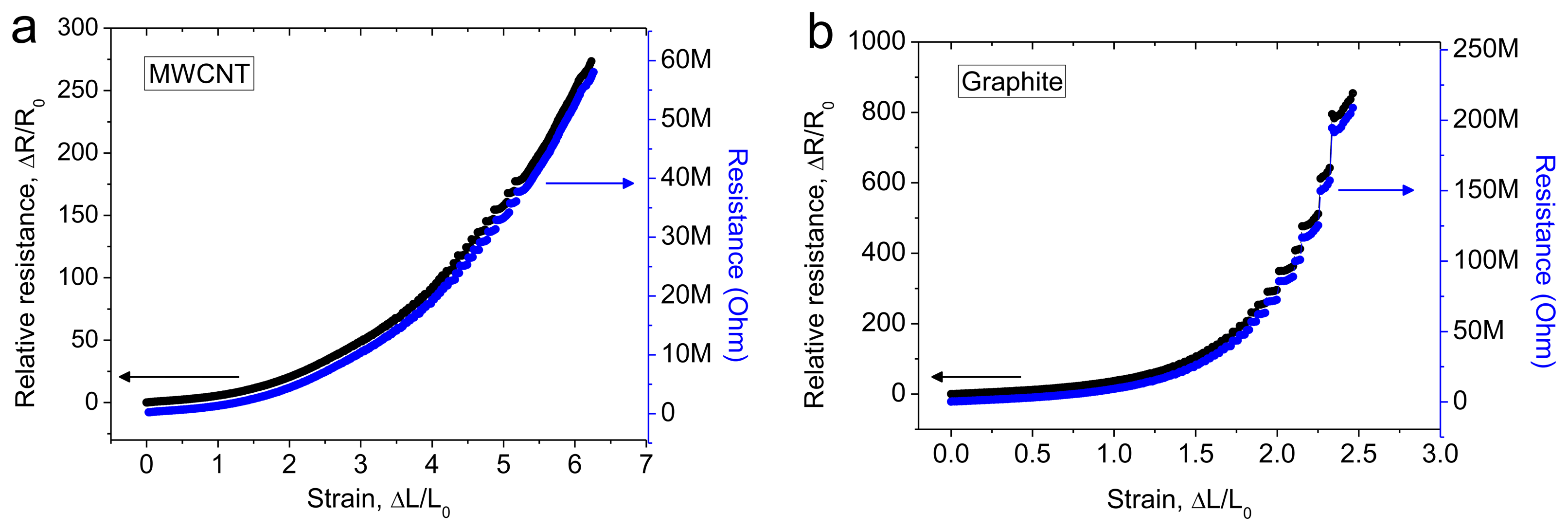
The MWCNT sandwich sample (gauge length 2 cm, width 1 cm) was stretched using a constant strain rate of 8.3% s−1, up to a strain of 620% (giving a final sample length of 14.4 cm). For the graphite flake sandwich sample (active gauge length 2 cm, width 1 cm), the maximum measured strain was 246% (giving a final sample length of 6.92 cm). The electrical resistance was measured by using Kelvin (4-wire) method. The resistance and relative change in resistance versus strain response curves are shown in Figure 3 for the MWCNT and graphite samples.
The resistance increased with the strain [1,4,5,7]. The carbon nanotube sensor showed a higher measurable strain limit (620%) compared with the graphite sensor (246%); this was likely because the nanotubes had a smaller size, compared with the graphite flakes. The sensitivity was calculated in terms of the gauge factor, using the formula gauge factor (GF) = relative resistance/strain, i.e., GF = [(R − R0)/R0]/[(L − L0)/L0], where R0 and L0 are the initial resistance and initial length of the sample, respectively. The sensitivity increased linearly with increasing applied strain for the MWCNT sensor, and the sensitivity increased exponentially with increasing applied strain for the graphite sensor. The sensitivity values for the MWCNT sensors were 5.5, 10.2, 16.3, 23.1, 31.5, and 43.4 at 100%, 200%, 300%, 400%, 500%, and 620% strain, respectively. The sensitivity values for the graphite sensors were 23.7, 37.5, 148.1, and 346.6 at 50%, 100%, 200%, and 246% strain, respectively.
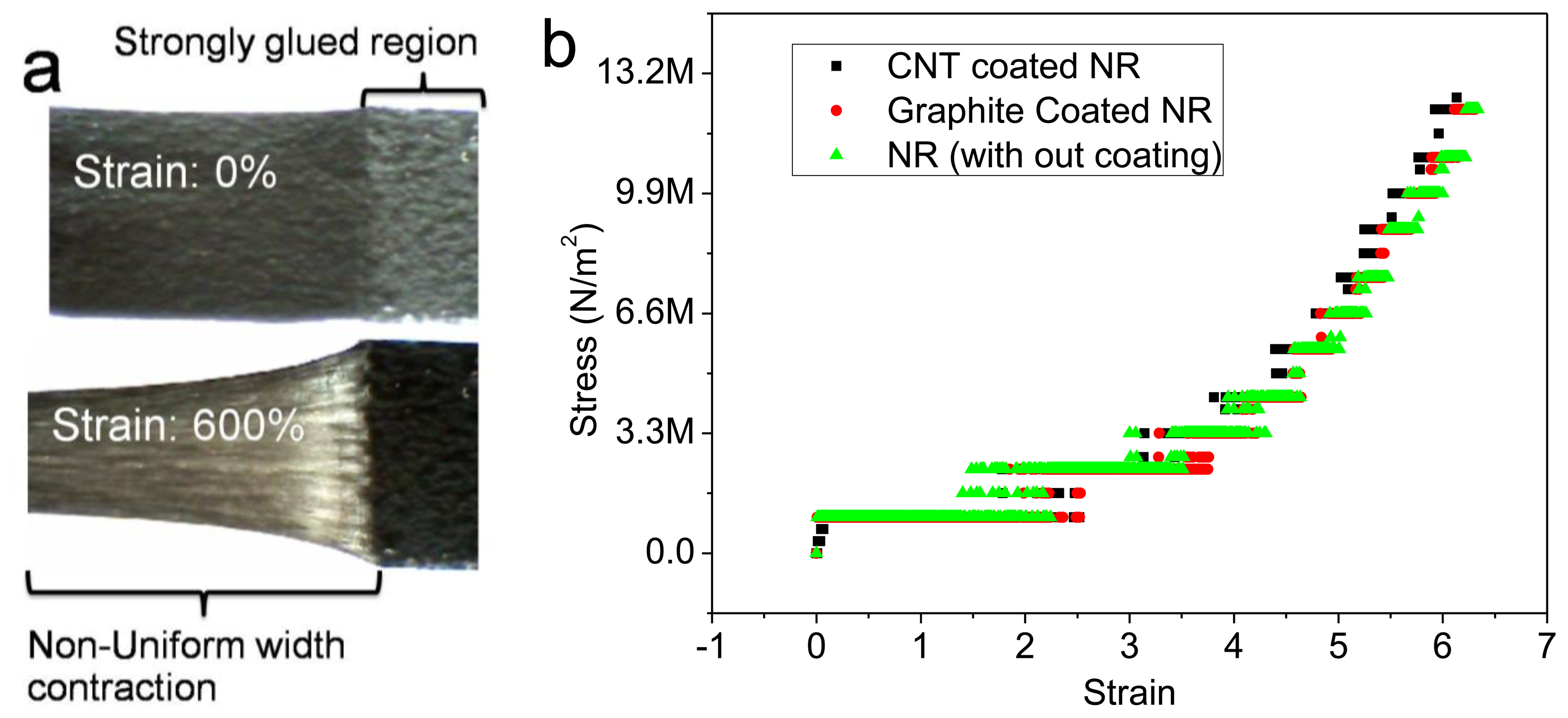
The relative change in the resistance response curves for the MWCNT and graphite sensors was nonlinear. It is likely that this nonlinear behavior resulted from the non-uniform fracturing/deformation of the conducting layers on the NR. When the sensor was subjected to stretch, the width contracted perpendicular to the longitudinal strain axis. During stretching, the freedom of the polymer chains to undergo contraction (perpendicular to the longitudinal strain axis) decreased exponentially with distance from the ends. This width contraction (or the lateral strain), was much lower at the sample's two ends, compared with the middle of the sample. This was because the sample ends were strongly bonded to the acrylic holding substrate with super-glue (Figure 4a). The stress versus strain curves for the MWCNT, graphite coated, and uncoated NR samples were identical and nonlinear (i.e., they did not obey Hook's law) (Figure 4b). At the ends of the sample where the polymer chains had less freedom to undergo contraction, the level of fracturing in the conducting layer was higher. This resulted in a reduction in the electrical percolation/number of tunneling contacts with increasing strain. The tunneling resistance may therefore have increased with the decrease in the electrical percolation/number of tunneling contacts [12–14].
3.2. Effect of Sensor Size on Linearity and Sensitivity
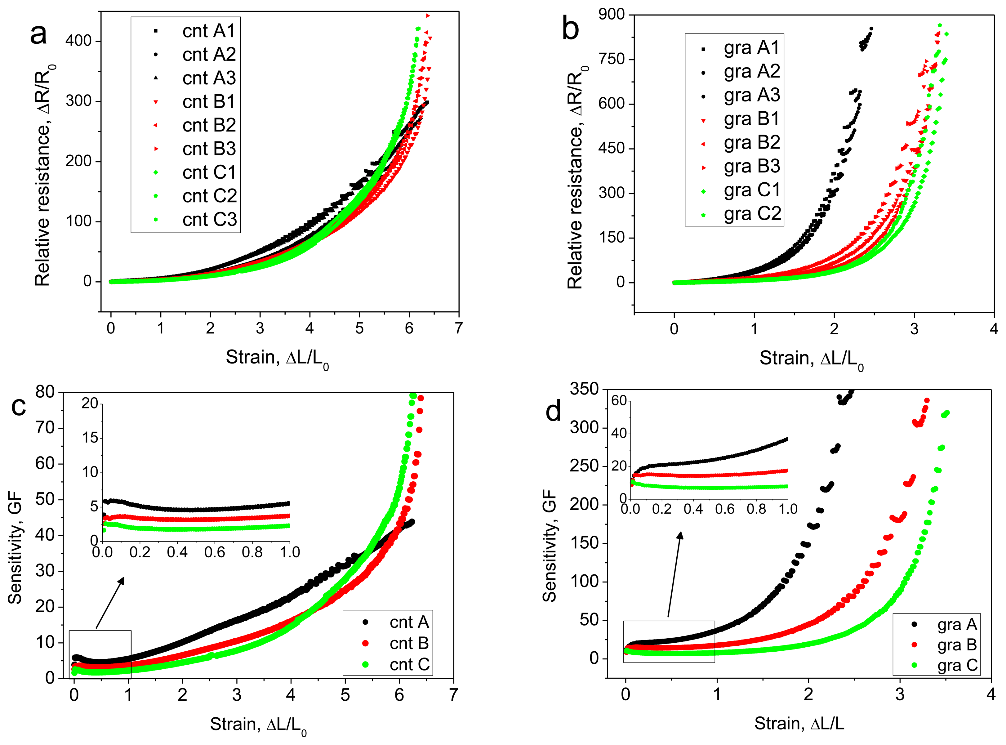
MWCNT and graphite sensors were prepared with a constant width of 10 mm, and three different lengths (active gauge lengths of (A) 20 mm; (B) 10 mm; and (C) 5 mm were prepared). The three samples A, B, and C were stretched using a constant strain rate of ∼8% s−1, and the electrical resistance was recorded. The longest MWCNT sensors and graphite sensors (10 × 20 mm) showed higher sensitivity than the shorter samples in the lower strain range. The shorter samples' response curves were highly nonlinear compared with the long samples, and at higher strain values the sensitivities of the shorter MWCNT samples surpassed the long samples' sensitivity. The measured relative resistance growth rate for the MWCNT sensors using sample sizes of W × L = 10 × 20 mm, 10 × 10 mm, and 10 × 5 mm were 0.548, 0.773, and 0.870, and those for the graphite sensors were 2.262, 2.298, and 2.430. The relative change in resistance versus strain and the sensitivity versus strain are shown in Figure 5 for the three different samples (A, B, and C).
For typical metallic strain sensors, the gauge factor value is constant (∼2) up to the maximum strain limit of 5%. Slobodian et al. [15] reported a sensor that could measure strains of up to 400% (MWCNT network in polyurethane); even at low strain values, its sensitivity changed linearly. Shin et al. reported a sensor (MWCNT forest in polyurethane) that showed constant sensitivity (0.34) up to a 30% strain limit. Yamada et al. reported constant sensitivity (0.82) up to a 40% strain limit. In the present work, the MWCNT/graphite sensor showed a constant sensitivity (5/12) for strain values of up to 100%.
3.3. Multiple Cycle Tests
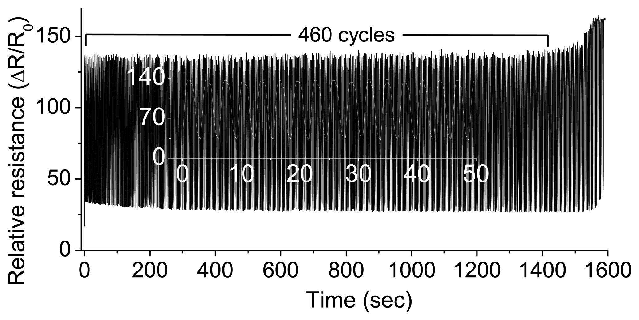
One end of the MWCNT strain sensor sample was attached to a disk, which was rotating with an angular velocity of 2 radians·s−1. The applied sinusoidal strain (with a period of ∼3.04 s) ranged between 150% and 500%, and the total number of cycles was more than 400 (Figure 6).
3.4. Linearization of Nonlinear Response Curves
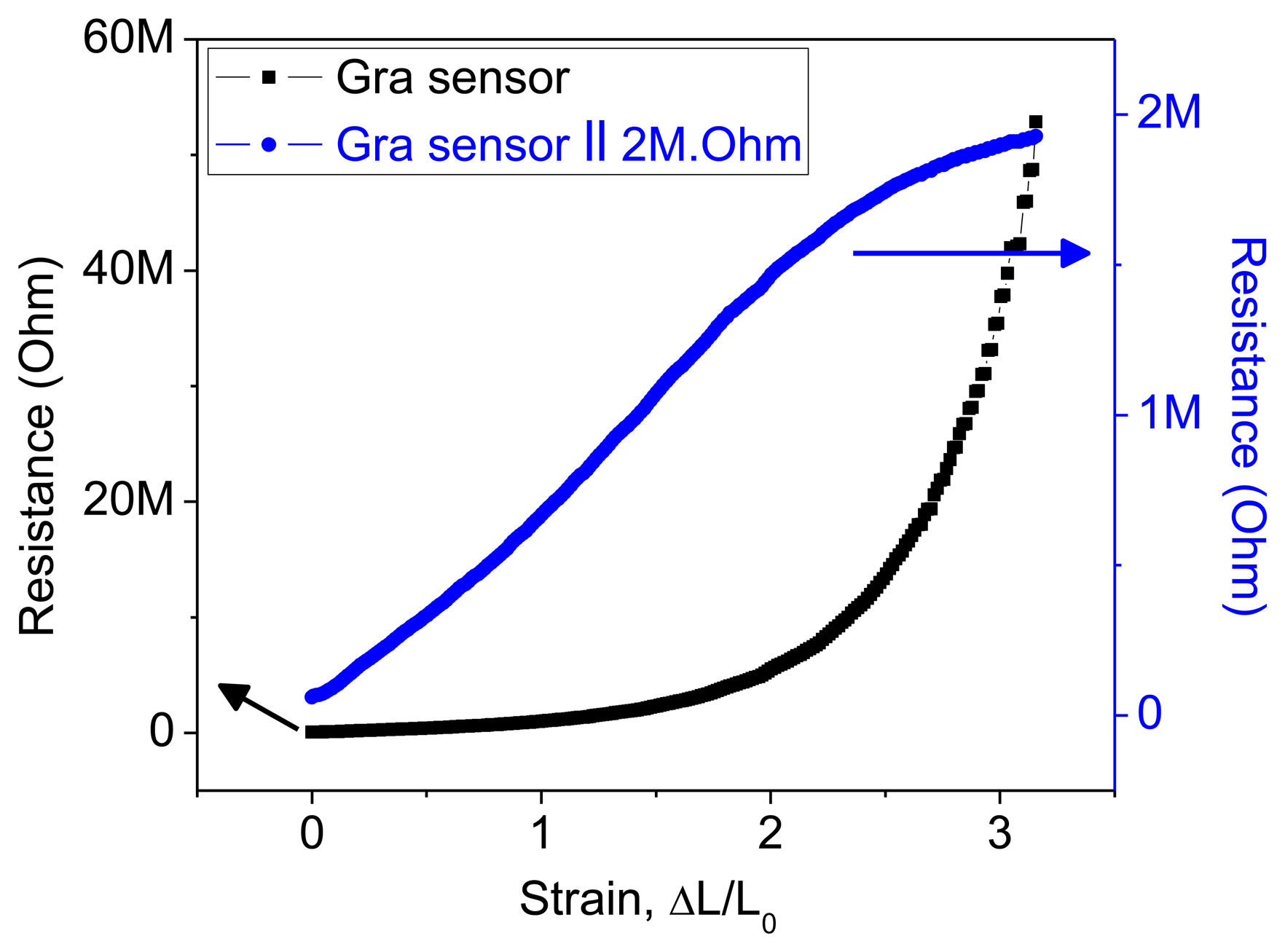
Metallic strain sensors' response curves are linear up to ∼5% of the maximum strain limit; for small strain values, therefore, the response curve for the graphite sensor appeared to be linear. However, the response curve over the whole region from 0% to 300% strain showed that this linearity was merely an approximation to the early part of an exponential curve. The linear response curve of conventional metallic strain sensors can therefore be considered as a small part of an exponential curve. A linear fit to an exponential response curve results in large errors. However, these exponential response curves could be linearized by connecting an external resistor parallel to the strain sensor. Resistance curves for the graphite sensor with and without a 2 MΩ parallel resistance are shown in Figure 7.
The coating of the MWCNT/graphite flakes on the prestretched substrate helped to maintain the electrical percolation and conducting pathways between the two electrodes (electric leads), even at high strains. Axial strain was applied using a lab-made speed control device. The two electrical leads from the test sample were connected to a constant power supply of 5 V (laboratory D.C power supply, GPC-1850D, Tucheng, New Taipei, Taiwan). The current flow in the circuit was measured using a Keithley-196 system DMM instrument, Cleaveland, Ohio, USA. The voltage drop across the sensor was measured (Kelvin method or 4-wire method) using a Hewlett Packard data acquisition-34970A (Santa Clara, CA, USA) instrument, and the output resistance was recorded using a computer. The surface morphology of the strained films was observed using FE-SEM (JSM-6335F, JEOL, Akishima, Tokyo, Japan).
4. Conclusions
To the best of our knowledge, these results are superior to those of any other previously reported strain sensor, in terms of the simple fabrication, high measurable strain (620%, limited by the substrate properties), and high sensitivity with good durability (400 cycles for 150%–500% strain range). These high-strain sensors could be used as multifunctional sensors [16] to measure, for example, force, speed, pressure, acceleration, frequency, structural vibrations, earthquakes or in health monitoring. The NR substrate has characteristic limitations that prevent its use in some environments, but these limitations could be overcome by replacing the NR substrate with other types of elastomers, for example, silicone rubber.
Acknowledgments
We thank the National Research University Project under Thailand's Office of the Commission on Higher Education (CHE) for financial support.
Conflicts of Interest
The authors declare no conflict of interest.
Supplementary Material
References
- Moshfegh, S.; Ebrahimi, N. Strain sensors based on graphite fillers. Iran Polym. J. 2004, 13, 113–119. [Google Scholar]
- Dobie, W.B.; Isaac, P.C.G. Electric Resistance Strain Gauges; English Universities Press Limited, 1948; Madison, WI, USA. [Google Scholar]
- Hu, B.; Chen, W.; Zhou, J. High performance flexible sensor based on inorganic nanomaterials. Sens. Actuators B: Chem. 2013, 176, 522–533. [Google Scholar]
- Zou, J.-F.; Yu, Z.-Z.; Pan, Y.-X.; Fang, X.-P.; Ou, Y.-C. Conductive mechanism of polymer/graphite conducting composites with low percolation threshold. J. Polym. Sci. Part B: Polym. Phys. 2002, 40, 954–963. [Google Scholar]
- Wang, L.; Ding, T.; Wang, P. Thin flexible pressure sensor array based on carbon black/silicone rubber nanocomposite. IEEE Sens. J. 2009, 9, 1130–1135. [Google Scholar]
- Dinh-Trong, N.; Steitz, J.; Bu, L.; Kanoun, O. Influence of the Composition of MWCNTs Layers on the Properties of Strain Gauges. Proceedings of the 9th IEEE Conference on Nanotechnology (IEEE-NANO 2009), Genoa, Italy, 26–30 July 2009; pp. 477–480.
- Li, X.; Zhang, R.; Yu, W.; Wang, K.; Wei, J.; Wu, D.; Cao, A.; Li, Z.; Cheng, Y.; Zheng, Q.; et al. Stretchable and highly sensitive graphene-on-polymer strain sensors. Sci. Rep. 2012, 2, 870. [Google Scholar]
- Levin, Z.S.; Robert, C.; Feller, J.F.; Castro, M.; Grunlan, J.C. Flexible latex-polyaniline segregated network composite coating capable of measuring large strain on epoxy. Smart Mater. Struct. 2013, 22, 1–9. [Google Scholar]
- Yamada, T.; Hayamizu, Y.; Yamamoto, Y.; Yomogida, Y.; Izadi-Najafabadi, A.; Futaba, D.; Hata, K. A stretchable carbon nanotube strain sensor for human-motion detection. Nat. Nanotechnol. 2011, 6, 296–301. [Google Scholar]
- Hin, M.; Oh, J.; Lima, M.; Kozlov, M.; Kim, S.; Baughman, R. Elastomeric conductive composites based on carbon nanotube forests. Adv. Mater. 2010, 22, 2663–2667. [Google Scholar]
- Singjai, P.; Changsarn, S.; Thongtem, S. Electrical resistivity of bulk multi-walled carbon nanotubes synthesized by an infusion chemical vapor deposition method. Mater. Sci. Eng. A 2007, 443, 42–46. [Google Scholar]
- Hu, N.; Karube, Y.; Arai, M.; Watanabe, T.; Yan, C.; Li, Y.; Liu, Y.; Fukunaga, H. Investigation on sensitivity of a polymer/carbon nanotube composite strain sensor. Carbon 2010, 48, 680–687. [Google Scholar]
- Li, X.; Levy, C.; Agarwal, A.; Datye, A.; Elaadil, L.; Keshri, A.K.; Li, M. Multifunctional carbon nanotube film composite for structure health monitoring and damping. Open Constr. Build. Technol. J. 2009, 3, 146–152. [Google Scholar]
- Xu, W.; Allen, M.G. Deformable strain sensors based on patterned MWCNTs/polydimethyl-siloxane composites. J. Polym. Sci. Part B: Polym. Phys. 2013, 51, 1505–1512. [Google Scholar]
- Slobodian, P.; Riha, P.; Saha, P. A highly-deformable composite composed of an entangled network of electrically-conductive carbon-nanotubes embedded in elastic poly-urethane. Carbon 2012, 50, 3446–3453. [Google Scholar]
- Li, C.; Thostenson, E.T.; Chou, T.-W. Dominant role of tunneling resistance in the electrical conductivity of carbon nanotube-based composites. Appl. Phys. Lett. 2007, 91, 223114:1–223114:3. [Google Scholar]


© 2014 by the authors; licensee MDPI, Basel, Switzerland. This article is an open access article distributed under the terms and conditions of the Creative Commons Attribution license (http://creativecommons.org/licenses/by/3.0/).
Share and Cite
Tadakaluru, S.; Thongsuwan, W.; Singjai, P. Stretchable and Flexible High-Strain Sensors Made Using Carbon Nanotubes and Graphite Films on Natural Rubber. Sensors 2014, 14, 868-876. https://doi.org/10.3390/s140100868
Tadakaluru S, Thongsuwan W, Singjai P. Stretchable and Flexible High-Strain Sensors Made Using Carbon Nanotubes and Graphite Films on Natural Rubber. Sensors. 2014; 14(1):868-876. https://doi.org/10.3390/s140100868
Chicago/Turabian StyleTadakaluru, Sreenivasulu, Wiradej Thongsuwan, and Pisith Singjai. 2014. "Stretchable and Flexible High-Strain Sensors Made Using Carbon Nanotubes and Graphite Films on Natural Rubber" Sensors 14, no. 1: 868-876. https://doi.org/10.3390/s140100868
APA StyleTadakaluru, S., Thongsuwan, W., & Singjai, P. (2014). Stretchable and Flexible High-Strain Sensors Made Using Carbon Nanotubes and Graphite Films on Natural Rubber. Sensors, 14(1), 868-876. https://doi.org/10.3390/s140100868