Surface Roughness Evaluation Based on Acoustic Emission Signals in Robot Assisted Polishing


Abstract
: The polishing process is the most common technology used in applications where a high level of surface quality is demanded. The automation of polishing processes is especially difficult due to the high level of skill and dexterity that is required. Much of this difficulty arises because of the lack of reliable data on the effect of the polishing parameters on the resulting surface roughness. An experimental study was developed to evaluate the surface roughness obtained during Robot Assisted Polishing processes by the analysis of acoustic emission signals in the frequency domain. The aim is to find out a trend of a feature or features calculated from the acoustic emission signals detected along the process. Such an evaluation was made with the objective of collecting valuable information for the establishment of the end point detection of polishing process. As a main conclusion, it can be affirmed that acoustic emission (AE) signals can be considered useful to monitor the polishing process state.1. Introduction
The increasing demand for improved surface integrity of manufactured components with high production rate has acted as a driving force in the development of automated production methods. For this reason, the monitoring of surface quality obtained by a manufacturing process has been extensively studied and improved in the last years. In fact, a great effort has been made to evaluate and control on line the surface roughness obtained in finishing machining processes by the analysis of signals detected by different sensors such as dynamometer, acoustic emission, accelerometer, current/power among others [1–7]. This is an important challenge to avoid valuable product rejects and refinishing [8,9].
Among these processes, polishing is the most common technology used in those applications in which high surface qualities, in terms of low roughness level, minimized subsurface damage and high form accuracies, are demanded. It is an essential step in optics manufacturing and in mold finishing operations [4].
The automation of polishing is especially difficult due to the high level of skill and dexterity that is required. Much of this difficulty arises due to a lack of data in relation with the effect of the polishing parameters on the resulting surface roughness, although some experimental works have been published in this area [10,11].
In general, these studies built up a specific database with experimental data and working knowledge that includes a set of polishing conditions such a tool type, size and grit, feed rate, number of passes and cutting fluids used [12–14].
Until now, regarding the monitoring of polishing processes, there are few experimental studies carried out [12,15–21].
In some of them, sensors have been integrated during the automated polishing processes. Among them, the use of acoustic emission sensors has allowed the achievement of valuable results for the estimation of the process state [12,17–21].
In this work, an experimental study was developed to evaluate the surface roughness obtained during robot assisted polishing processes by the analysis of acoustic emission (AE) signals. The aim is to find out a trend of a feature or features calculated from the AE signals obtained along the process. Such an evaluation was made with the objective of collecting valuable information for the establishment of the end point detection of polishing process; this is when the required surface roughness is reached or it is necessary to replace the tool and select a finer one and/or change other polishing condition, to carry on with the following stage of polishing.
For this propose, dry polishing turning tests were carried out on a Robot Assisted Polishing machine (STRECON NanoRAP 200) performed during five polishing sessions, at different polishing contact force, using the same polishing stone tool. Along the tests, AE signals were acquired and roughness surface measurements were taken at the end of each polishing session.
2. Experimental Procedure
The experimental procedure taken in this study is shown on the following points:
2.1. Polishing Tests
For the development of the tests, it is proposed to employ a Robot Assisted Polishing (RAP) system. This is a polishing machine equipped with a robot arm in which interchangeable polishing tools are mounted. A control module is integrated in the robot arm that allows the setting of, not only the conventional polishing parameters such a cutting speed and feed rate, also the contact force between the tool and workpiece, and the tool pulsation. This movement increases the cutting efficiency and improves the steadiness of the machining process.
In this study, dry polishing turning tests were carried out on a Robot Assisted Polishing machine (STRECON NanoRAP 200) performed during five polishing sessions, at different polishing contact force. Experimental tests were taken on a bar of alloy steel (UNS G52986) with a length of 75 mm and diameter of 30 mm (Figure 1). This machine operates similarly to a turning lathe. In this case, the operation performed was a cylindrical turning in which three movements are combined: the rotation of the workpiece, the feed movement of the tool and a third movement; the tool has also a pulsation movement on the feed direction with a frequency of 500 pulses/min on a length of 1 mm.
The abrasive tool selected was the polishing stone with a grit number of 800 that corresponds to a grain size of approximately 11 μm from Gesswein (MP800) according to the Comercial Standard CS271-65 [22].
Each session consists of 60 polishing passes. The Table 1 summarizes polishing conditions used in each session.
2.2. Acquisition of AE Signal during Polishing Tests
An AE sensor was mounted on the tool holder as close as possible to the polishing stone to minimize signal loss and achieve a good signal-to-noise ratio. Signals samples were taken with an interval time between acquisitions of, approximately, 0.93 s. That is, along the five polishing sessions, a total number of 4650 acquisitions. Sample rate was set up for 1 MHz.
2.3. Surface Roughness Measurements
At the end of the each polishing session, five surface roughness measurements were taken on the workpiece (along one of its generatrix) by the use the roughness tester MahrSurf XD1 equipped with a 2 μm radius tip. For the measurements, it was applied a cut-off and an evaluation length of 0.25 and 1.25 mm, respectively.
In the measurement process, data (xi, zi) of the surface geometry workpiece were obtained. The arithmetical average roughness, Ra, was selected as a parameter to analyze. According to ISO 4288 (ISO 4288, 1996) [23] standards, this parameter is defined as the arithmetical average of the absolute values of the deviations of the roughness profile, R, and it is expressed mathematically by means of the Equation (1):
2.4. Analysis of AE Data
Row AE signal data arrays, with 131,072 values each of them, are stored and analyzed by Matlab software. Different features were calculated to determine the process state, in terms of surface roughness, along the polishing time.
From AE data, an analysis in the frequency domain was carried out by using the Fast Fourier Transform (FFT) algorithm. This is an efficient algorithm that allows the representation of a digital signal in the frequency domain using less number of numerical operations compared to Digital Fast Fourier (DFT) with a substantial computational power saving [24].
Firstly, FFT power spectral graphics at different polishing time were plotted. The objective is to select a range or ranges of frequencies where the amplitudes of certain peaks shown in the FFT power spectral plots decrease with the time process, as it is pointed out in previous studies in which robot assisted polishing tests were carried out [18,24]. Once the range of frequencies was selected, maximum amplitude was calculated from all the AE acquisitions registered to achieve a possible trend and a correlation with the surface roughness.
3. Results
As a first approach, FFT power spectral plots were obtained at different polishing time corresponding to the acquisitions taken, approximately, at the middle of each polishing session.
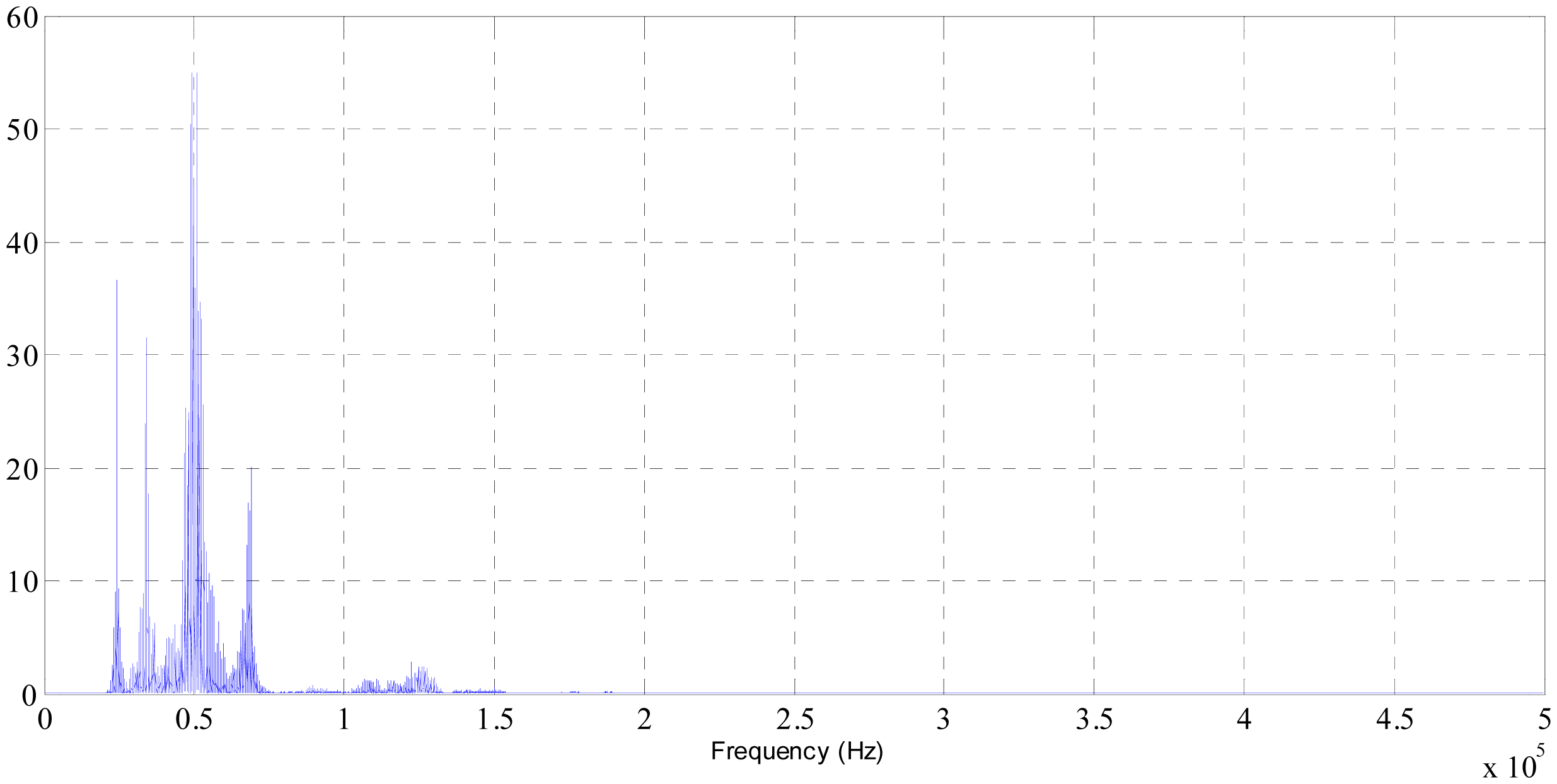
All of them show several peaks that appear around the same range of frequencies as it can be seen in Figure 2. This is the FFT power spectral plot at 0400 acquisition during the session 1. As it was mentioned, the amplitude of some of those peaks decreases as process progresses, whereas magnitudes on other frequencies do not show a variation over time.
In addition, it is important to remark that when a higher magnitude of contact force was applied, the amplitudes of these peaks increased. This direct relationship, between the selected AE signal parameter and the contact force, was observed at the last session of polishing (session 5).
Further analysis was made to evaluate the whole polishing process; this is the total acquisitions taken during the five sessions. According to the peaks shown in the FFT power spectral representations, different ranges of frequencies were selected to determine the maximum amplitude of the different peak reached. Among the ranges of frequencies analyzed (ranges that contain peaks at 24, 34 50, 69 and 125 kHz) the selected range that is shown in this study, is the range between 60,000 and 100,000 Hz, so a clearer trend was found. Similar results are presented in the study developed by Pilný and partners [18], in which three main peaks were distinguished at 20, 45 and 150 kHz.
Maximum amplitudes calculated from each acquisition along the five polishing sessions are plotted in the following Figure 3.
As it can be observed, as the polishing process progresses, the amplitudes tend to decrease, apart from the ones obtained at the fifth session, for the reason that was previously pointed out.
Besides, at the end of each polishing session, five surface roughness measurements were taken on the workpiece, around the same location.
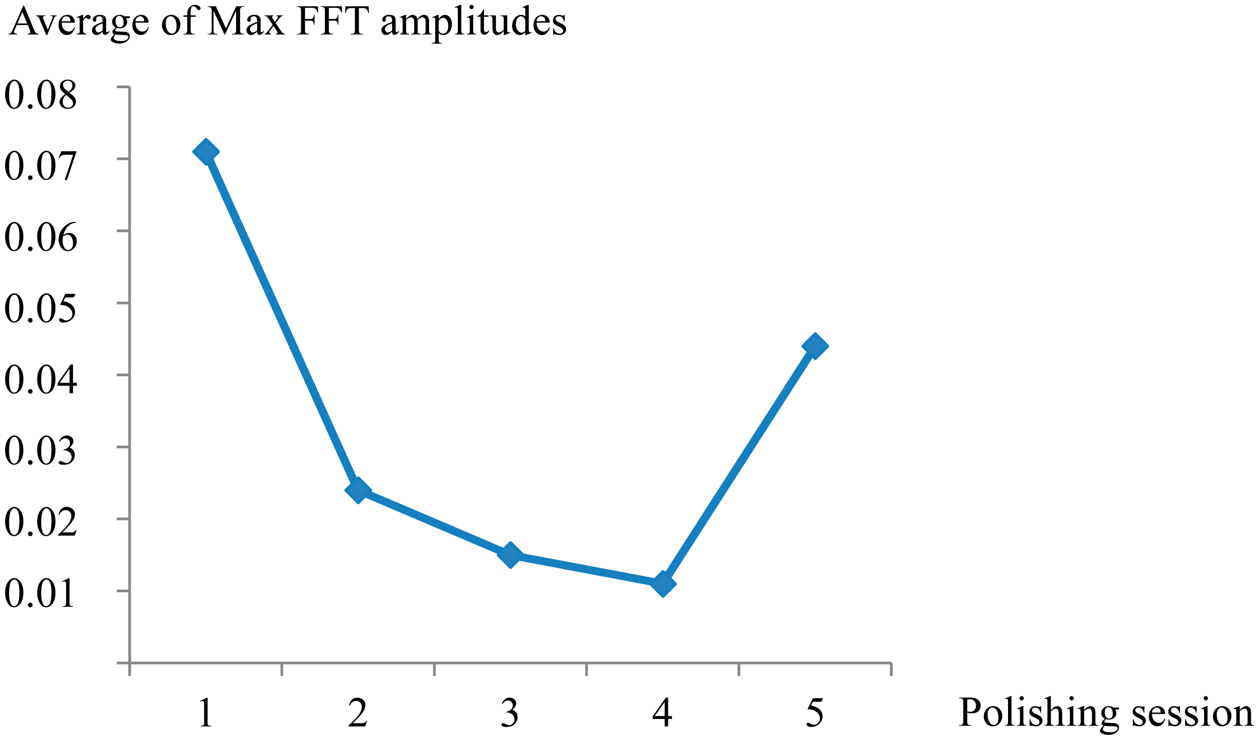
Finally, to compare the results from the analysis of AE signals in the frequency domain and the obtained surface roughness, the averages of maximum amplitudes of FFT power spectral were plotted in Figure 4 and the five Ra measurements for each polishing season were plotted by means of box and whisker diagrams (Figure 5).
First of all, it is important to clarify with respect the Figure 5, that the values of the surface roughness measured on the workpiece before polishing is included and plotted at the polishing session number 0.
As shown in Figures 4 and 5, the feature extracted of AE signals and the surface roughness follow the same trend, obtaining the lowest value of Ra (0.059 μm) at the fourth polishing session. This is when it would be approached the end detection of the process. Afterwards, at the fifth polishing session, with the increase of the contact force applied up to 17.64 N, a larger value of Ra was obtained. Nevertheless, at first stage of polishing process (session 1) with the use of a higher magnitude of contact force, at the same cutting condition, the surface roughness improved from 0.142 to 0.116 μm. This shows that it is necessary to reduce such control parameters for the last polishing stages.
4. Conclusions
As a first approach, in this study, an evaluation of the surface roughness obtained by Robot Assisted Polishing with different contact force applied between the tool and the workpiece, was developed. Concretely, dry polishing turning tests were carried out on a bar of alloy (UNS G52986) by using a tool with a grit number of 800. An analysis of the AE signal in frequency domain detected during the process was made with the objective of finding a feature or features from AE signal sensitive to the variations of the surface roughness measured along five polishing sessions. The main conclusions extracted from the results obtained in this study can be summarized as follows:
- ‐
For the polishing conditions employed in this study, the surface roughness and the analyzed feature calculated from the frequency domain of AE signal (maximum amplitude of the FFT power spectral between the frequencies 60,000 and 100,000 Hz) during polishing process follow the same trend. Therefore, AE signal can be considered useful for the monitoring of polishing process state.
- ‐
The end point detection of the process was determined at the end of the polishing session 4. That corresponds to the polishing stage when the most improved surface roughness has been reached.
- ‐
The contact force between the tool and the workpiece is a control parameter of the process that should be reduced at the last polishing stages.
- ‐
Finally, it is important to indicate that from the results obtained in this study, it is possible to collect valuable data to use together with other features extracted from others sensors to further develop monitoring polishing systems.
Acknowledgments
The authors thank to the Research Group of the UNED “Industrial Production and Manufacturing Engineering (IPME)” for the given support during the development of this work, and the funding of: the European project (FP7 IFaCOM reference: 285489), the Spanish Ministry of Science and Innovation (Project DPI2011-27135) and the Industrial Engineering School-UNED (Project REF2013-ICF03).
Author Contributions
Teti and Rubio, has participated in the idea and the planning of the different stages of the experimental procedure in this research paper, as well as in the analysis of results and final conclusions reached. Marín, Rubio and Agustina have participated in the analysis of the results and final conclusions extracted.
Conflicts of Interest
The authors declare no conflict of interest.
References
- Eversona, C.E.; Cheraghi, S.H. The application of acoustic emission for precision drilling. J. Mach. Tools Manuf. 1999, 39, 371–387. [Google Scholar]
- Dongfeng, S.; Gindy, N. Development of an online machining process monitoring system: Application in hard turning. Sens. Actuators 2007, 135, 405–414. [Google Scholar]
- Karayel, D. Prediction and control of surface roughness in CNC lathe using artificial neural network. J. Mater. Process. Technol. 2009, 209, 3125–3137. [Google Scholar]
- Klocke, F.; Dambon, O.; Schneider, U.; Zunke, R.; Waechter, D. Computer-based monitoring of the polishing processes using LabView. J. Mater. Process. Technol. 2009, 209, 6039–6047. [Google Scholar]
- Marinescu, I.; Axinte, D. A time–frequency acoustic emission-based monitoring technique to identify workpiece surface malfunctions in milling with multiple teeth cutting simultaneously. Int. J. Mach. Tools Manuf. 2009, 49, 53–65. [Google Scholar]
- Teti, R.; Jemielniak, K.; O'Donnell, G.; Dornfeld, D. Advanced monitoring of machining operations. CIRP Ann. Manuf. Technol. 2010, 59, 717–739. [Google Scholar]
- Núñez, P.J.; Simao, J.; Arenas, J.M.; de la Cruz, C. Surface roughness characterization using cutting force analysis, regression and neural network prediction models. Mater. Sci. Forum 2006, 256, 211–216. [Google Scholar]
- Guo, Y.B.; Ammula, S.C. Real-time acoustic emission monitoring for surface damage in hard machining, damage in hard machining. Int. J. Mach. Tools Manuf. 2005, 45, 1622–1627. [Google Scholar]
- Azouzi, R.; Guillot, M. On-line prediction of surface finish and dimensional deviation in turning using neural network based sensor fusion. Int. J. Mach. Tools Manuf. 1997, 37, 1201–1217. [Google Scholar]
- Wu, B.H.; Wang, J.J. A neuro-fuzzy approachto generating mold/die polishing sequences. J. Mater. Process. Technol. 2009, 209, 3241–3250. [Google Scholar]
- Huissoon, J.P.; Ismail, F.; Jafari, A.; Bedi, S. Automated polishing of die steel surfaces. Int. J. Adv. Manuf. Technol. 2002, 19, 285–290. [Google Scholar]
- Ahn, J.H.; Shen, Y.F.; Kim, H.Y.; Jeong, H.D.; Cho, K.K. Development of a sensor information integrated expert system for optimizing die polishing. Robot. Comput. Integr. Manuf. 2001, 17, 269–276. [Google Scholar]
- Brinksmeier, E.; Riemer, O.; Gessenharter, A.; Autschbach, L. Polishing of structured molds. CIRP Ann. Manuf. Technol. 2004, 53, 247–250. [Google Scholar]
- Takaya, Y.; Tachika, H.; Hayashi, T.; Kokubo, K.; Suzuki, K. Performance of water-soluble fullerenol as novel functional molecular abrasive grain for polishing nanosurfaces. CIRP Ann. Manuf. Technol. 2009, 58, 495–496. [Google Scholar]
- Kim, S.Y.; Park, C.J.; Seo, Y.J. Signal analysis of the end point detection method based on motor current. Microelectron. Eng. 2003, 66, 472–479. [Google Scholar]
- Lee, D.E.; Hwang, I.; Valente, C.M.O.; Oliveira, J.F.G.; Dornfeld, D.A. Precision manufacturing process monitoring with acoustic emission. Int. J. Adv. Manuf. Technol. 2006, 46, 176–188. [Google Scholar]
- Ahn, J.H.; Lee, M.C.; Jeong, H.D.; Kim, S.R.; Cho, K.K. Intelligently automated polishing for high quality surface formation of sculptured die. J. Mater. Process. Technol. 2002, 133–134, 339–344. [Google Scholar]
- Chang, Y.P.; Hashimura, M.; Dornfeld, D.A. An investigation of the AE Signals in the lapping process. CIRP Ann. Manuf. Technol. 1996, 45, 331–334. [Google Scholar]
- Jeong, H.; Kim, H.; Lee, S.; Dornfeld, D. Multi-Sensor monitoring system in Chemical Mechanical Planarization (CMP) for correlations with crocess issues. CIRP Ann. Manuf. Technol. 2006, 55, 325–328. [Google Scholar]
- Pilný, L.; Bissacco, G.; de Chiffre, L.; Ramsing, J. Acoustic Emission based In-process Monitoring in Robot Assisted Polishing. Proceedings of the 11th International Symposium of Measurement Technology and Intelligent Instruments, Aachen, Germany, 1–3 July 2013.
- Dunegan, H. An Acoustic Emission Technique for Measuring Surface Roughness; the DECI Report; Dunegan Engineering Consultants Inc.: Midland, TX, USA, 1998. [Google Scholar]
- U.S. Department of Commerce. Grading of abrasive grain for grinding wheels Commercial Standard CS 271-65. 1965.
- ISO 4288:1996 Geometrical Product Specifications (gps). Surface Texture: Profile Method. Rules and Procedures for the Assessment of Surface Texture; ISO: Genève, Switzerland, 1996.
- Lazarev, R. Monitoring and Control of Fine Abrasive Polishing Processes. Ph.D Thesis, University of Southern Denmark, Sønderborg, Denmark, 2012. [Google Scholar]


| Polishing Session | Contact Force (N) | Spindle Speed (rpm) | Feed Rate (mm/s) | Pulsation Tool (Pulses/min) | Pulsation Stroke (mm) |
|---|---|---|---|---|---|
| 1 | 17.64 | 300 | 5 | 500 | 1 |
| 2 | 9.8 | ||||
| 3 | 9.8 | ||||
| 4 | 9.8 | ||||
| 5 | 17.64 |
© 2014 by the authors; licensee MDPI, Basel, Switzerland. This article is an open access article distributed under the terms and conditions of the Creative Commons Attribution license ( http://creativecommons.org/licenses/by/4.0/).
Share and Cite
De Agustina, B.; Marín, M.M.; Teti, R.; Rubio, E.M. Surface Roughness Evaluation Based on Acoustic Emission Signals in Robot Assisted Polishing. Sensors 2014, 14, 21514-21522. https://doi.org/10.3390/s141121514
De Agustina B, Marín MM, Teti R, Rubio EM. Surface Roughness Evaluation Based on Acoustic Emission Signals in Robot Assisted Polishing. Sensors. 2014; 14(11):21514-21522. https://doi.org/10.3390/s141121514
Chicago/Turabian StyleDe Agustina, Beatriz, Marta María Marín, Roberto Teti, and Eva María Rubio. 2014. "Surface Roughness Evaluation Based on Acoustic Emission Signals in Robot Assisted Polishing" Sensors 14, no. 11: 21514-21522. https://doi.org/10.3390/s141121514