Toward a New Generation of Photonic Humidity Sensors

Abstract
: This review offers new perspectives on the subject and highlights an area in need of further research. It includes an analysis of current scientific literature mainly covering the last decade and examines the trends in the development of electronic, acoustic and optical-fiber humidity sensors over this period. The major findings indicate that a new generation of sensor technology based on optical fibers is emerging. The current trends suggest that electronic humidity sensors could soon be replaced by sensors that are based on photonic structures. Recent scientific advances are expected to allow dedicated systems to avoid the relatively high price of interrogation modules that is currently a major disadvantage of fiber-based sensors.1. Introduction
Water is the most essential chemical compound for humans on the Earth. Life, as we know it, is impossible without water. More than 70% of the surface of our planet is covered by water. Water is present everywhere, in air, in soil, in rocks, in plants and an animals. In air or in other gasses water can exist in two different forms. The term moisture refers to water in liquid form that is suspended in air or gas in form of small droplets. The term humidity refers to the concentration of water vapor in air, where the water is in a gaseous phase.
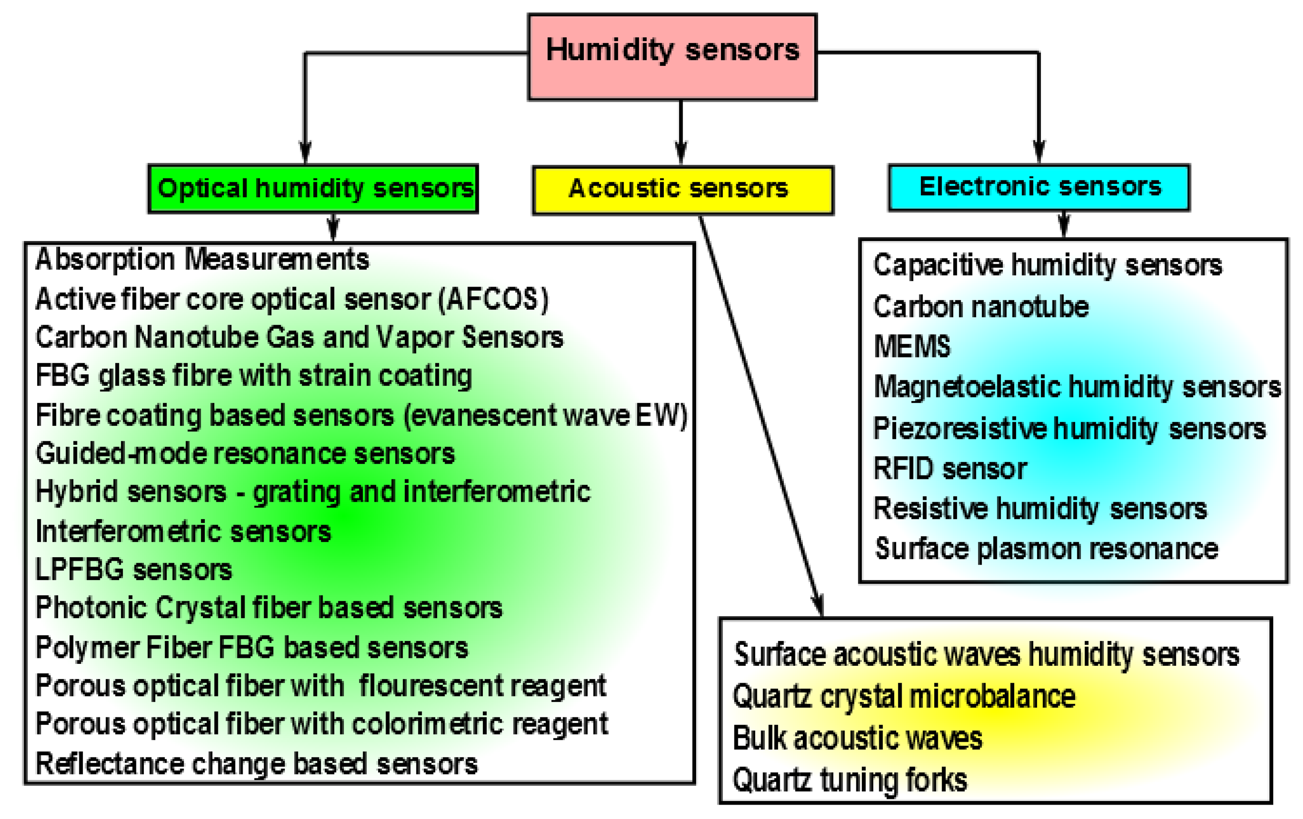
Humidity is a physical quantity that has significant importance in a number of areas ranging from life sciences [1,2] to building automation [3]. Hence humidity control, sensing and monitoring is important in a number of areas. Fast humidity sensors are required for the diagnosis of pulmonary diseases [4] and for mapping the human respiratory system [5] by monitoring the water vapor content of exhaled breath. For meteorological applications [6] sensing of humidity is important as it indicates the likelihood of precipitation, dew or fog. In the semiconductor industry, the performance of photo-resist is critically dependent on the humidity. In the electronics industry, humidity monitoring is important as electronic items may malfunction due to high humidity. Furthermore, humidity control is essential in some buildings where humidity sensitive materials are stored such as museums, archives, warehouses. For human comfort and to maintain the quality of a number of food products, it is important to control humidity levels inside buildings, cars, shops and other places. Many different types of humidity sensors are needed to cover all the previously mentioned applications. As a consequence, a wide range of sensor types (see Figure 1) has been proposed for humidity measurements.
In Figure 1, humidity sensors have been organized into three groups. Electronic sensors are the most common type of sensors today. This technology has a very long history and follows the first generation of mechanical humidity sensors. These mechanical sensors were based mainly on change in the mechanical properties of some materials. These materials were frequently of animal origin, for example, horse or human hairs. These first mechanical sensors, which were slow and imprecise, were used throughout human history until the second half of twentieth century. At that time, practically simultaneously with the first electronic chips, the second generation of the humidity sensors has emerged. These were electronic humidity sensors. Today, humidity sensing based on electronic sensors is the dominant technology.
More recently, research has been carried out on the use of acoustic waves to measure humidity. So far, this research has not led to the development of new sensors and little research is currently being reported in this area in comparison with other humidity sensing areas. However, a third generation of sensors has now emerged with the development of fiber technologies. These sensors, which are mainly based on interferometric techniques, are faster and more robust than the electronic ones. This technology, which has been developed over the past twenty years, is now making its first attempts to compete with the well-established electronic one. Today, humidity sensors based on fiber interferometers still have a relatively high cost in comparison with electronic ones. However the fiber sensors have some important advantages. These sensors do not generate electrical sparks because the optical humidity sensors do not use electricity in the sensor head. This allows the use of optical humidity sensors in chemical industry, where flammable solvents are frequently employed.
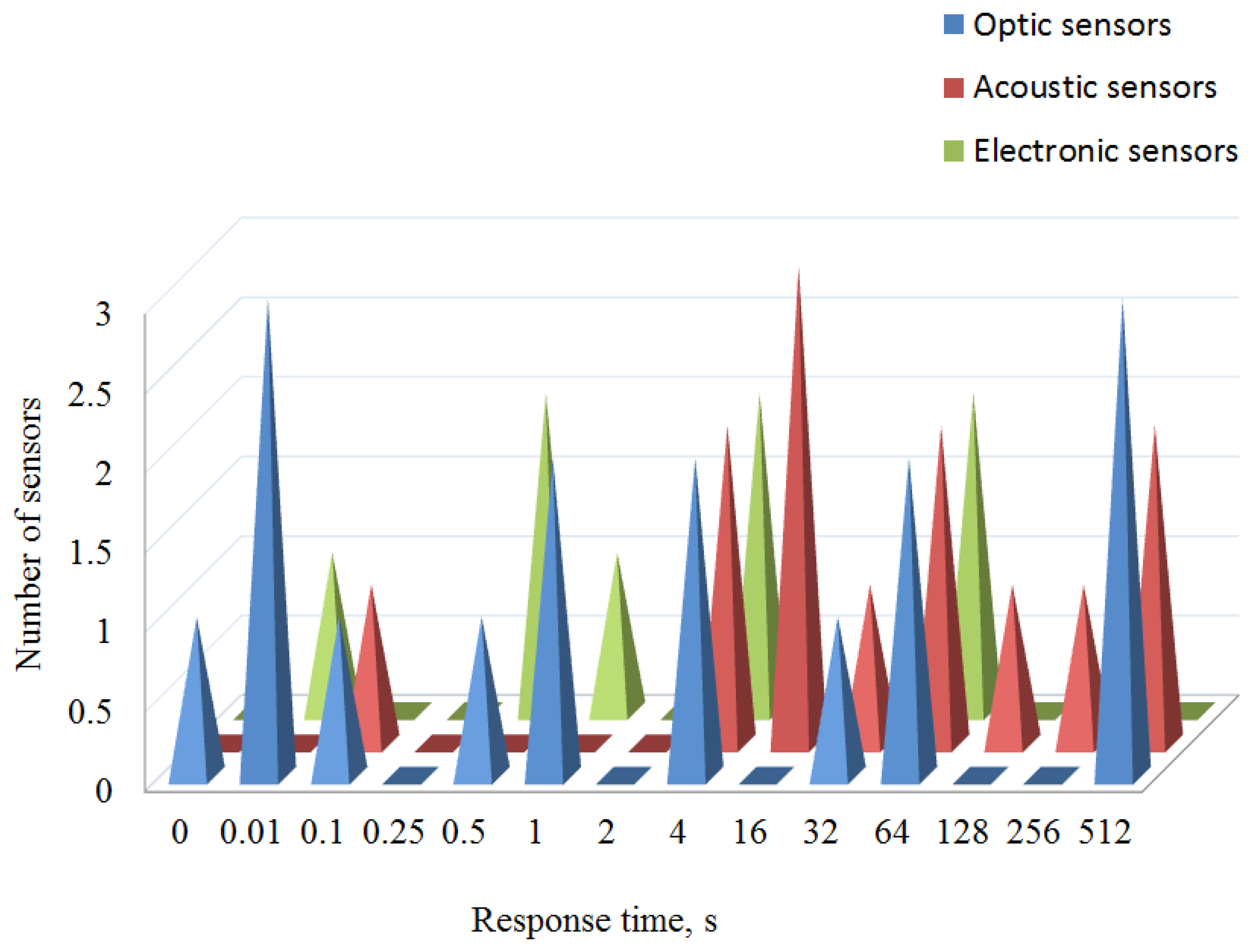
A comparison between response time of different types of humidity sensors is illustrated in Figure 2. The acoustic sensors (red color) are slowest group. The second group (green color) are experimental and commercially available electronic sensors. Finally, the blue color illustrates the performance of optical humidity sensors. The fastest sensors, which are depicted on the left side of Figure 2, are interferometric sensors and have a response time of less than one second. These sensors are based on photonic crystal fibers and use poly-vinyl-alcohol as the hydrophilic material.
Current research draws attention to the fact that important technological advances have been made during the last ten years in all competing branches of humidity sensing technologies. A new generation of nano-technology based humidity sensors, complimentary metal oxide semiconductor micro-electro-mechanical system (CMOS-MEMS) humidity sensors have been investigated and demonstrated [7]. These sensors have an extremely fast response time in comparison with the electronic sensors that prevail in the market. The main advantages of these devices are their simplicity and the availability of low cost interrogation modules. However, the sensitive head of these sensors is expensive to produce in small quantities. Another kind of optical humidity sensor, which is based on nano-capillary interferometer [8–11] has been widely investigated in scientific literature. This sensor has a very simple and cheap sensing element. The manufacturing of these elements does not require a large investment in machinery, allowing on demand production. One purpose of this article is to examine the most current research in the area of humidity sensing. This review offers new perspectives and highlights an area in need of further research. Moreover, the report includes a review of recent scientific literature mainly covering the last ten years. The second section of the article is devoted to a review of the latest advances in the field of electronic humidity sensing. Progress in the field of acoustic humidity sensing is examined in the next section. Finally, in the forth section, the state-of-art in optical humidity sensing is described. The major findings indicate that a new generation of humidity sensing technology based on optical fibers is emerging.
2. Electronic Humidity Sensors
This section discusses the main characteristics of state-of-the-art electronic sensors for humidity detection and recent research in this area. Today these sensors are the dominant technology on the world-wide market. They detect humidity by measuring changes in the electrical characteristics of a humidity-sensitive thin film. The relatively simple design and low price of the interrogation module are the two main advantages of electronic sensors. On the other side of the coin their disadvantages are: the need for regular calibration; the difficulty in measuring relative humidity below 5% level; poor linearity and relatively long response time, which typically is of several tenth of seconds or even minutes. Moreover, the use of electronic humidity sensors in certain critical environments, remote places, potentially explosive atmospheres and areas with high electromagnetic interference is either difficult or some times impossible.
Research over the past ten years has been largely aimed at improving these characteristics and this will be discussed in the remainder of this section. In the electronic sensors, water vapor is absorbed into some hydrophilic layer and this changes the impedance of the device. Contacts are applied to the layer to measure this change. Commercially available humidity sensors are briefly reviewed in the first subsection. In the following subsections, the detectors will be classified by whether changes are measured in the capacitance or the resistance of the sensor. The second subsection is dedicated to a description of the experimental advances in the field of capacitative humidity sensors. Finally, humidity sensors that are based on resistivity changes are illustrated in the last subsection.
2.1. Commercially Available Humidity Sensors
Electronic humidity sensors, which are typically available for less than $10, are the most commonly available low cost sensors today. Despite the low cost, these devices are quite sophisticated. Most of these sensors can be connected directly to a microprocessor without requiring an external amplifier or digitizer. The integration of a temperature sensor allows the measured data to be corrected for temperature variations. In addition, an external microprocessor can calculate both the dew point and the concentration of water vapor. However, these commercial devices fall short of requirements in some areas as is listed below:
too long response time in some applications
a poor accuracy, which is close to ±2%, especially at low and high humidity
wide hysteresis and poor linearity
insufficient temperature operational range and bad long term stability.
The response time of these sensors is typically in the range 5–60 s. Although this is adequate for many applications, it is too long in some other areas such as for a breathing sensor. The accuracy is limited to a few percent RH and is worse in the extreme ranges of 0%–10% RH and 90%–100% RH. The devices have hysteresis, in other words the detector output for a given humidity depends on whether the humidity is increasing or decreasing. The maximum width of this hysteresis is typically a few percent RH. The maximum operating temperature is in the range 80–120 °C which is not high enough for some industrial drying applications. Finally, if the temperature of a humidity sensor drops below the dew point, condensation will prevent it operating until the temperature of the sensor has been increased for long enough for the water to evaporate. This is a common problem with humidity sensors. Some examples of performance of commercially available sensors are summarized in Table 1.
2.2. Capacitive Humidity Sensors
Capacitive sensors are typically produced by depositing a thin layer of a sensitive material on to closely spaced electrodes. Sometimes, these electrodes take the form of two interdigitated comb structures to increase the capacitance. This allows water vapor to interact with the top surface of the sensitive layer. Moreover, the interdigitated electrodes are simpler to produce using photolithography than a structure with electrodes on both sides. Capacitive sensors have the advantages of low power requirements and a high output signal. Clearly, the performance of a capacitive sensor will depend critically on the sensitive layer used. Table 2 lists the properties of capacitance sensors using different sensitive layers.
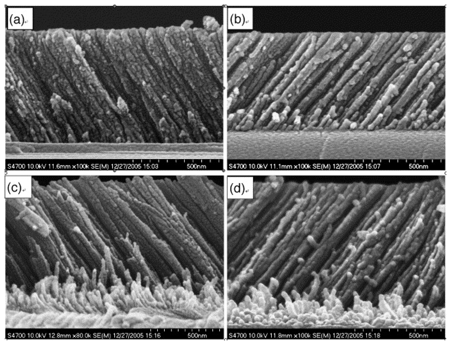
The trend to minimize the size of electronic devices reveals itself in the research and design of new humidity sensors [12,13]. Recently a new generation of electronic sensors based on CMOS-MEMS [7], nano-technology [14–18] and capacitive [19] technology has been reported in the scientific literature. These new sensors are based on nano-structured TiO2 thin films and have a reaction time which is approximately ten times shorter [19] than the devices that are widely used today. Figure 3 shows a nano-structured thin TiO2 film that was deposited using glancing angle deposition (GLAD).
Porous inorganic materials, such as porous silicon, have been investigated however organic materials have the potential for significantly lower cost. These can be prepared by low cost techniques such as spin coating, drop casting, dip coating or spray coating. Nickel phthalocynine (NiPc) and poly-N-epoxy-propyl-carbazole (PEPC) have been found to be sensitive to humidity. Ahmad et al. [20] have investigated the performance of mixtures of these compounds with copper oxide. The addition of copper oxide will increase the surface roughness to produce a larger surface area and has the potential to produce a greater sensitivity and reduced response time. Using this technique three times greater sensitivity was obtained however this material was only suitable for an operating range above 40% RH.
Graphene oxide is an interesting material for achieving a high sensitivity and fast response time due to its single layer nature and hydrophilic surface. Bi et al. [21] have investigated the use of these films as a humidity sensor. They improved the sensitivity by a factor of ten compared with conventional capacitance sensors and their sensor had a reasonable response time of 10.5 s for increasing humidity although this increased to 41 s for reducing humidity. The variation of the impedance of these structures with frequency was complicated and the devices only operated over a range of 15%–95% RH.
Multi-wall carbon nano-tubes (MWCNTs) [22] where the tube diameter varies are of interest for improving the performance of humidity sensors at low humidity due to capillary condensation. This is an effect where condensation can occur in thin capillaries at significantly below the saturation vapor concentration. The radius r required for condensation at a vapor pressure p is given by the Kelvin equation:
The relatively slow response of standard humidity sensors is a disadvantage in applications involving transient humidity changes such as in industrial process control and for monitoring atmospheric humidity. Kang and Wise [23] have developed a faster sensor based on polyimide that has a response time of around 1 s. Their design was based on an analysis of the diffusion into the sensor material. By etching the sensitive material into an array of pillars, they find that the increased surface area reduces the diffusion time by a factor often. By using pillars with diameters of 15, 10 and 5 μm the response time was reduced to 6.9, 1.9 and 1.0 s respectively. A second feature of their design was to include an integrated poly-silicon heater and temperature sensor. This was used to prevent the temperature dropping below the dew point to maintain a short time of response and also to measure high humidity without having the sensor exposed to it. Using the heater, the relative humidity was calculated using the formula [23]:
For a low-cost device, there is considerable advantage if the sensor material is compatible with silicon processing. Thin organic films fall into this category and several papers have described sensors compatible with MEMS [25,26] or CMOS [27,28] technology. The CMOS used top level metal and a standard passivation layer as the sensor. A self-calibration circuit was added to simplify the operation. MEMS technology allows multiple sensors (for temperature, humidity, pressure, wind speed and wind direction) to be integrated on a single chip.
2.3. Resistive Humidity Sensors
As with capacitive sensors, recent research on resistive sensors has been aimed at improving their sensitivity, response time, linearity and hysteresis characteristics.The characteristics of some recently reported resistive humidity sensors are listed in Table 3. Arshaka et al. have investigated the use of thermally deposited In2O3 [32] and sintered pastes of MnZn ferrite [33] and achieved low hysteresis and good linearity.
Kuang et al. [34] have investigated the properties of a single SnO2 nano-wire as a resistive humidity sensor. The use of a single nano-wire will lead to a very small sensor and may lead to a faster response time. The growth process resulted in a high concentration of oxygen vacancies leading to the surface of the nano-wire being very sensitive to oxygen and water vapor in the air. Characterization of this device showed a reproducible linear response with response and recovery times in the range 120–170 s and 20–60 s respectively. Lee [35] has researched the properties of nano-structured carbon nitride CNx films deposited by radio-frequency (RF) sputtering. The CNx bonds are expected to react reversibly with hydrogen and hydroxyl groups to generate a hydrophilic surface which can absorb and release water molecules. The resulting layers were found to have a reasonably linear response with a hysteresis which depended strongly on the substrate used. This was due to the formation of ink bottle shaped defects which trap water in the interior.
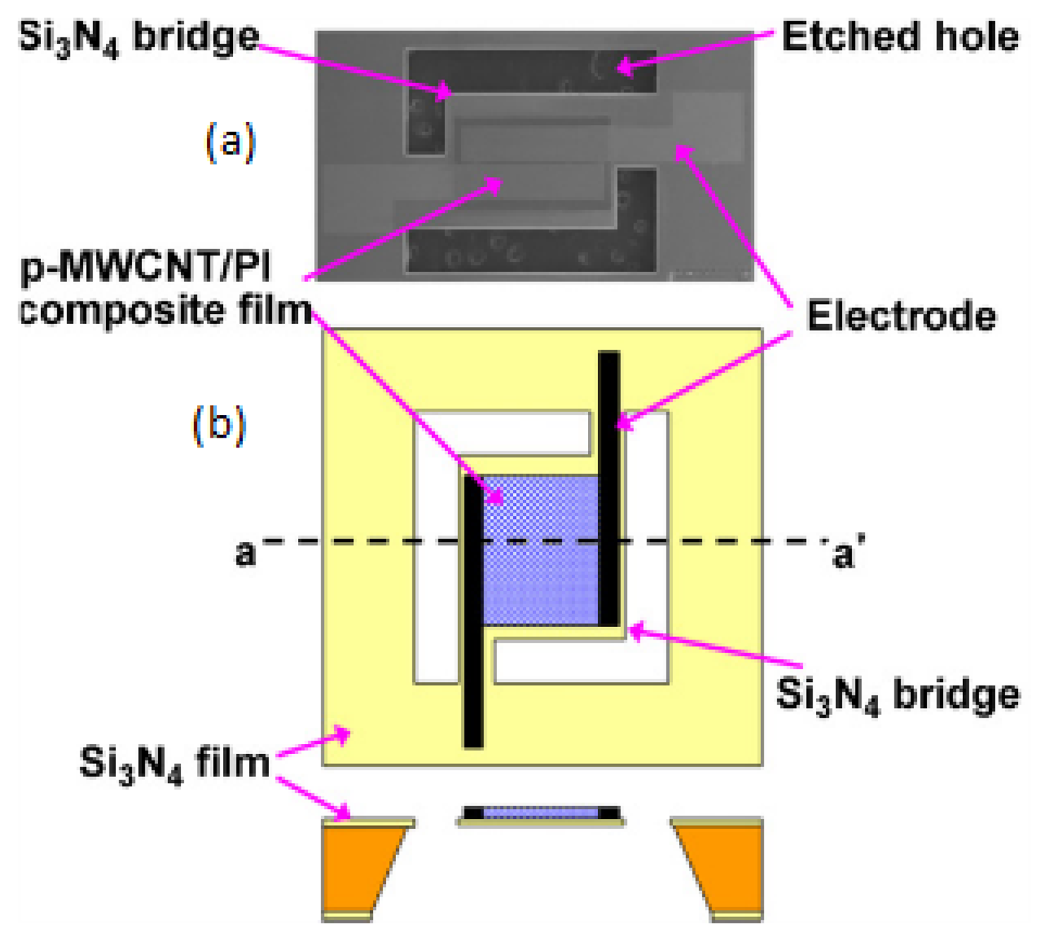
Polyimide films have been successfully used as capacitive humidity sensors however they have also been considered for use as resistive humidity sensors. Although the resistance of these devices is very sensitive to humidity, with the resistance changing by many orders of magnitude, they are not ideal humidity sensors due to their variability (requiring calibration), highly non-linear response and poor response at low humidity. Yoo et al. [17] have investigated a sensor that was manufactured by adding plasma-treated MWCNs to the polyimide film to improve its performance. As the doping level was increased, the resistance of the films remained very high until the density exceeded the percolation threshold of 0.05% where the resistance dropped rapidly. At sufficiently high concentrations, the resistance is governed by transport of electrons through the continuous paths, which the nano-tubes form. Increasing the humidity is found to increase the resistance due to a combination of charge transfer between the MWCNs and the water molecules, which reduces the mobile carrier concentration in MWCNs, and increased pressure due to swelling of the polyimide. For a nano-tube concentration of 0.4%, this leads to a highly linear variation of resistance with humidity.
The extremely small size of these sensors drastically improves characteristics. The typical design of p-MWCNT/PI composite sensor is shown on Figure 4. Standard silicon micromachining was used to produce a thin film suspended over a silicon substrate. One major advantage of these sensors is their high linearity over the entire operational range. These sensors exhibit a sensitivity of 0.0047% RH.
3. Acoustic Humidity Sensors
In this section humidity sensors based on acoustic wave technology are reviewed. Acoustic methods of humidity measurements can be classified as mechanical methods. This measurement technique is based on the variation of mechanical properties of a hydrophilic material when water molecules are absorbed on to it. Existing methods of humidity measurement are based on surface acoustic waves (SAW), the change in the resonance frequency of a quartz crystal microbalance (QCM), quartz tuning forks (QTF) and on bulk acoustic waves (BAW) technology. The change in frequency of the acoustic resonance is typically used for detecting the change of material density that occurs because of absorption of water vapor from the surrounding atmosphere [39,40]. The change of density of the hydrophilic material changes the resonance frequency. This frequency shift has been theoretically analyzed by Sauerbrey [41]. The Sauerbrey equation gives the frequency shift of a quartz oscillator due to absorption of a small mass Δm of water:
This section is organized as follows: in the first subsection we provide a review of most relevant achievements in the branch of SAW sensors, the second subsection describes the state-of-art in the sector of quartz crystal microbalance humidity sensors. Although, there are not many publications devoted to investigating of BAW and QTF humidity sensors we have included a short description of advances in this area in the third subsection. Moreover, we have gathered together the most relevant characteristics of all these types of acoustic sensors in Tables 4 and 5.
3.1. Surface Acoustic Waves Humidity Sensors
Generally, SAW sensors are based either on organic molecules or on polymers whose interactions with the absorbed water molecules leads to a change in the velocity of surface waves. During the last decade experimental efforts have been focused on improving the surface quality and testing new hydrophilic materials. Various techniques such as drop coating [62], the Langmuir-Blodgett technique [63], spin coating [64], coating using the method of fast expansion of a supercritical solution (RESS) [65], electro-sprayed silicon-containing polyelectrolyte [66] and air-brush coating [67] have been considered for the deposition of the active material. For the electro-spray coating process, Li [44] has examined the influence of the polymer deposition rate and polymer solution concentration on the properties of the humidity sensor.
The effect of droplet diameter on intrinsic acoustic losses in the sensor have been investigated by Sarcar and co-workers [68]. Sarkar compared the coating film quality and performance of the sensor that was coated using the AC electro-spray technique with similar ones that were coated using the DC electro-spray technique, the air-brush and RESS. They concluded that much lower acoustic losses were obtained using the DC electro-spray process due to the rapid evaporation of the nano-droplets.
Very fast SAW sensors based either on thin films of poly-vinyl-alcohol (PVA) or on thin films of poly-vinyl-pyrrolidone (PVP) have been described by Buvailo [69]. These sensors show response/recovery times 1.5/2.5 s respectively in the humidity interval of 5%–95%.
3.2. Quartz Crystal Microbalance Humidity Sensors
These sensors tend to be quite slow in comparison with SAW sensors, with a response time of hundreds of seconds and quite non-linear behavior. However, some interesting findings have recently been published.
A hybrid sensor has been demonstrated by Shinbo [52]. This sensor was fabricated by depositing either slab or ridge optical waveguides made of fluorinated polyimides on the quartz crystal microbalance. Accurate discrimination of adsorbed chemical species has been successfully performed by observing the change in the mass load and either the optical transmittance or optical spectrum.
Su and co-workers [53] have compared the behavior of a sensor using composite of nafion with single-wall carbon nano-tubes (SWCNTs) with a sensor using multi-wall embedded carbon nano-tubes. This sensor showed quasi-linear behavior and a recovery time close to 100 s. Novel low-humidity sensors were fabricated in situ using photo-polymerization of polypyrrole nano-particles [54]. These sensors showed good sensitivity at low humidity and an unusually short response time. The authors associated this phenomenon with high local electrostatic charge of TiO2 nano-particles, which caused dissociation of water molecules.
In [55] it was shown that the sensitivity of fibrous composite polyacrylic acid (PAA)/polyvinyl-alcohol membranes was two times higher than the sensitivity of a corresponding flat film at 95% RH. The membranes based on fibrous composite have the highest sensitivity because of their extremely high surface area.
The use of zinc oxide has been investigated in [56,58,59]. These experiments have confirmed the well known fact [50] that the thickness of the sensitive film needs to be optimized in order to achieve the best possible performance. In addition, it was concluded that the structure of the zinc oxide film was important for sensor performance. Films structured in the form of either nano-rods or nano-wires showed slightly better performance than films structured in form of nano-tetrapods.
Finally, the hydrophilic potential of MWCNT [57] was investigated using measurements with QCM. The sensor, operating in the range between 5% and 95% of RH, has the response/recovery times of 60 and 70 s respectively and exhibits linear behavior.
3.3. Bulk Acoustic Waves and Quartz Tuning Forks Humidity Sensors
The resonant frequency of these devices strongly depends on temperature and research aimed at reducing the sensor temperature dependence is presented in [60]. This sensor takes advantage of the coexistence of fundamental and higher order resonance modes in the interval 30–100 MHz. The temperature dependence of the sensor has been successfully compensated in the range from 20% to 92% RH over the temperature range from 25 to 70 °C.
Zhou et al. [51] have presented the application of QTF coated with nano-crystalline ZnO film as a relative humidity sensor. Moreover, the interferences, which can be induced by either ethanol or acetone vapors have been discussed. The results shown that the uniformity of the ZnO film is important for the performance of the sensor.
4. Optical Humidity Sensors
The intensive investigation of the potential of optical fiber sensors began in the middle of the 1980s, after the first optical fibers became commercially available. At that time, the technology for electronic sensing was already well established. However, from the beginning, optical sensors have been successfully employed for a range of specific applications which electronic sensors are unable to perform. These include electromagnetic compatibility, multi-point measurements and the possibility of remote interrogation. Additional advantages of fibre sensors include miniature size and small weight. All these features make optical fibre sensors suitable for applications where electronic or acoustic ones are either not recommended or inappropriate. For example, fibre sensors offer a solution for monitoring parameters such as temperature and humidity inside microwave ovens. Optics sensors do not use electricity and consequently they can be used for monitoring of inflammable liquids or gases because of the absence of sparks. Fibre sensors are also a viable alternative in harsh environments such as those with corrosive substances [70]. Some of these sensors are also chemically inert, which allow their use in chemical reactors. Moreover, these sensors have been successfully used for monitoring historical objects in remote places [71]. For these reasons the acceptance of fibre sensors in several industrial sectors is growing steadily. Characteristics of some optical humidity sensors, which are commercially available today are summarized in in Table 6.
The research on optical humidity sensors started about 25 years ago. During the last 20 years the prices of fiber components have fallen and the quality of these components has been improved. The available range of fiber based sensors has significantly increased and can replace traditional sensors in many applications such as gyroscopes, tension and bending sensors, stress sensors, humidity and water level sensors.
For humidity sensing, a range of different techniques and approaches have been proposed including spectroscopy, change of reflectance of surfaces [72], evanescent wave interactions [73], Bragg and long period gratings [74–78], interferometers [79], carbon nano-tubes [14] and more recently, photonic crystal fibres [8,80]. Most fibre optic humidity sensors require a hygroscopic material, which is typically deposited on a section or on the tip of the optical fibre [81]. Humidity changes the optical properties of the material, which in turn, modifies a feature of the guided light giving rise to a detectable signal. Bedoya [82] has discussed an interesting fiber-optic humidity sensor based on the optical properties of indicator dyes.
In this section we will summarize the technological advancements that have recently emerged in the branch of sensors based on optical fiber technology. In the first subsection the latest achievements in the interferometric humidity sensing are reviewed. The second subsection is dedicated to the humidity sensors that are based on long period gratings. Advances in hybrid relative humidity sensors are illustrated in the third section. Finally, in the fourth and the fifth subsections the progress in humidity sensing based on evanescent-waves interactions and some other exotic humidity sensors are described. The main features of some optical fibre-based humidity sensors are summarized in Tables 7 and 8.
4.1. Interferometric Humidity Sensors
Interferometric techniques are the most exact and fastest of all the existing optical methods of measurement. Interferometric relative humidity sensing has been successfully tested in medicine [97] to monitor human breathing. This application in particular is useful for the diagnosis and study of the progression for such serious diseases as the sleep apnea syndrome. The most significant characteristics of humidity sensors based on interferometric measurements are their relative simplicity, extremely high sensitivity and short time of response. The main advantage of interferometric humidity sensing is the absence of hydrophilic material that can be easily damaged when the sensor works in a harsh environments [70]. The main disadvantage of these sensors is their low selectivity. This sort of sensors measures the changes in the refractive index of the atmosphere next to the fibre, consequently they are sensitive to a variety of contaminants. For this reason the interferometric techniques have sometimes been complemented by the use of hydrophilic materials. Numerous research groups have investigated diverse sensor architectures to improve sensor sensitivity and robustness.
The sensor based on the fiber Sagnac interferometer was developed by Chen [98]. The hydrophilic material called chitosan has been used in this sensor. Chitosan swells when the humidity is increased. This was used to produce strain and changes the polarization properties of the fiber. This sensor was compared with the sensor implemented in Fabry-Perot geometry using the same material [81]. The sensor based on Fabry-Perot geometry showed an extremely short response time of 380 ms.
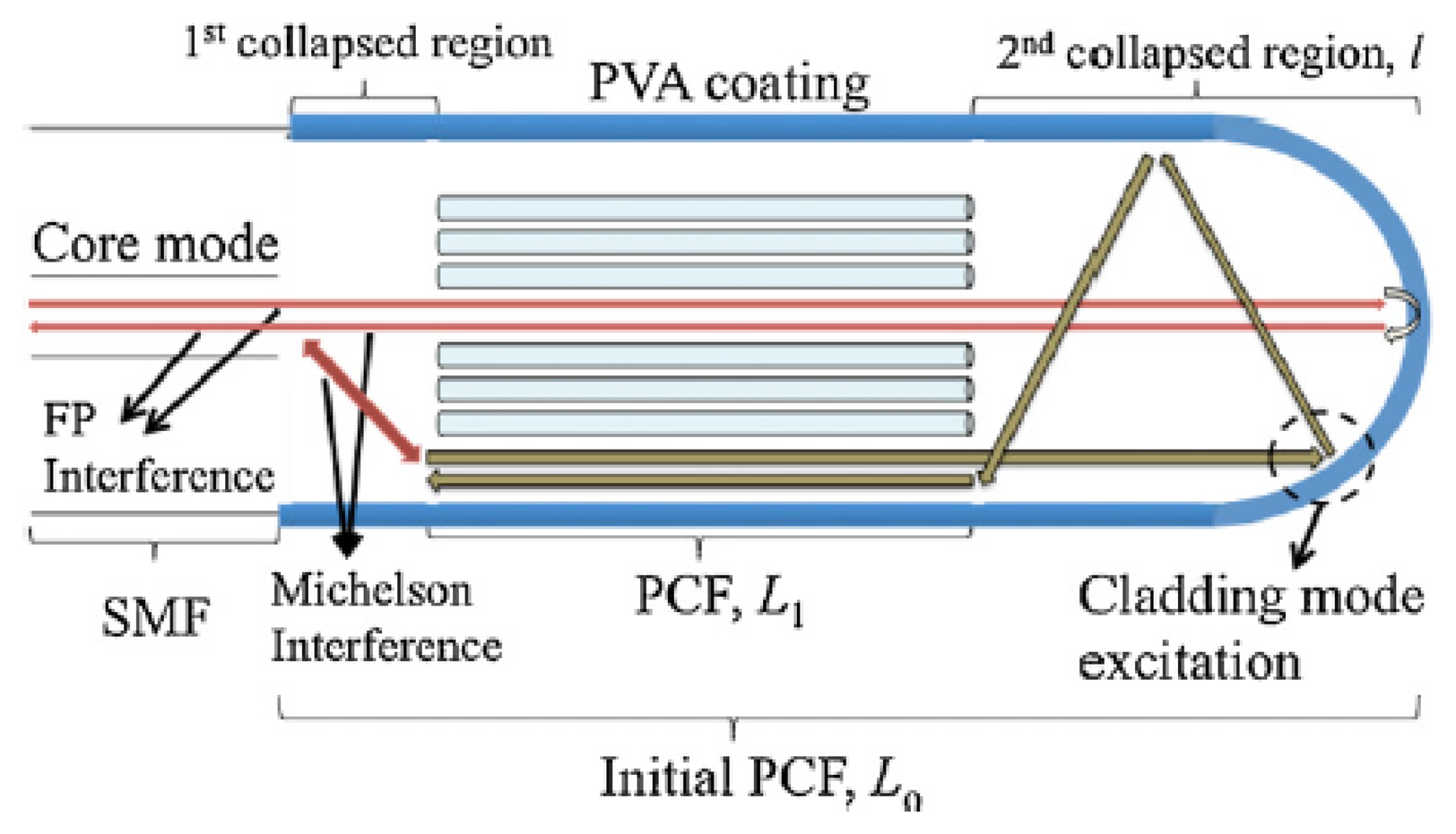
A miniature optical RH sensor based on a polymer infiltrated photonic crystal fiber was reported by Mathew [99]. Experiments showed that the sensitivity of a sensor based on photonic crystal fiber can be improved [100] by infiltrating the voids of the photonic crystal with a hydroscopic polymer. At a later date, Wong [94] combined PVA, which is considered to be a very promising material for humidity sensing, with the interferometric technique proposed by Mathew [100]. The sensor is illustrated in Figure 5. The sensor with a 9% (w/w) coating achieved a sensitivity of 0.60 nm/% RH, exhibited little hysteresis, high repeatability, low cross-sensitivity to temperature and ammonia gas and stable performance during a seven day testing period. Moreover, the sensor showed short rise/fall times of 300/500 ms respectively.
Finally, Liang [101] investigated the combination of a PVA coating and loop mirror based on polarization maintaining fiber. His experiments showed quite a narrow range of sensitivity between 20% and 85% RH.
4.2. Humidity Sensors Based on Long Period Grating
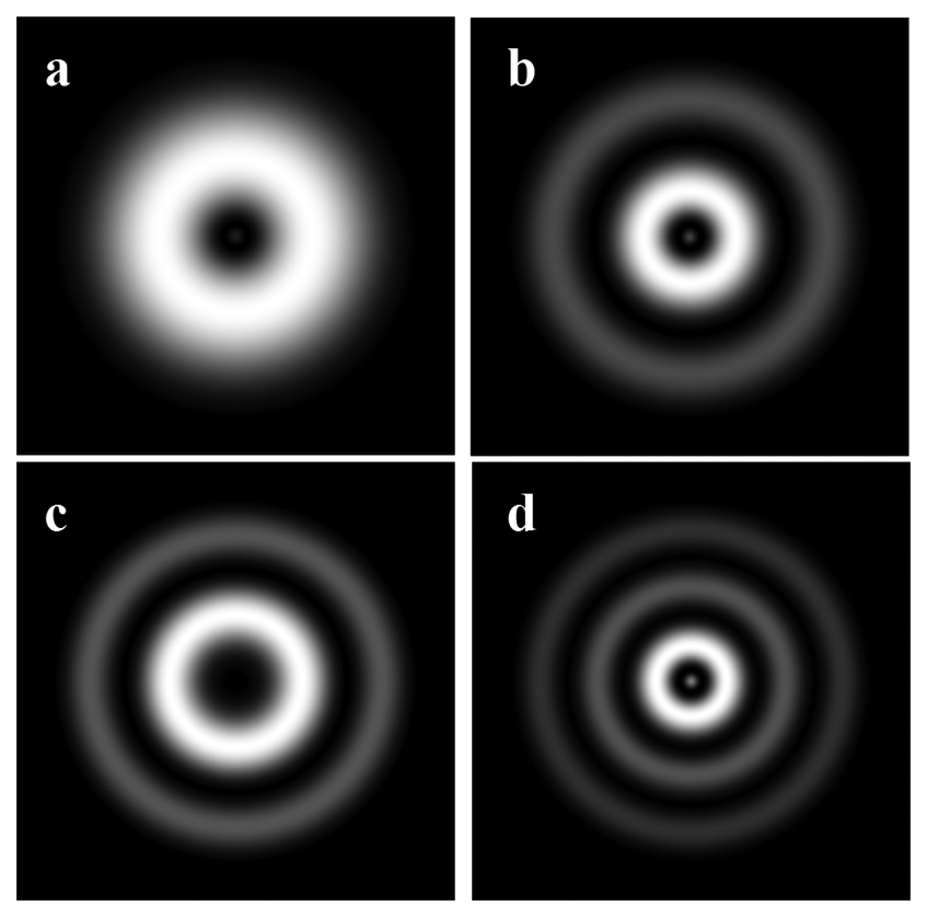
This subsection will review research on humidity sensors based on long period fiber gratings (LPFG). In this kind of sensor a LPFG is used to excite cladding modes [102]. In Figure 6 the theoretical distribution of intensity of some cladding modes are illustrated. The experiential images of intensity distribution of HE15 and HE16 cladding modes can be find out, for example, in [103]. Cladding modes are extremely sensitive to changes in the refractive index of the material that surrounds the fiber. This property of the cladding modes is widely used for sensing applications. However, these sensors have some disadvantages. For example, Alwis [104] reported that the attenuation bands formed by the coupling between the propagation mode in the core and the cladding modes are very broad when an LPFG based sensor in transmission mode is used.
Often, the segment of fibre with the exited cladding modes is coated with some hydrophilic material. This improves the sensitivity and selectivity of the sensor so that it is mainly sensitive to humidity changes. Other fiber coatings, which have been investigated recently were based on thin films of calcium chloride [106], poly(ethylene oxide)/cobalt chloride (PEO/CoCl2) [107], diamond-like carbon [108], hydrogel [109,110], polyimide coating [111].
Venugopalan [112] reported LPFG with a PVA coating. Surprisingly, this sensor showed a relatively long response time of 50 s. The range of humidity sensing was only from 33% to 97% RH. In other types of humidity sensors this coating has achieved significantly better performance. Viegas [113] achieved an improvement in the sensitivity in a range 20% to 80% of a sensor, which was coated with a film of SiO2 nano-spheres using deposition through electrostatic self-assembly. As a result, the wavelength shift was increased from 5 to 15 nm.
4.3. Hybrid RH Sensors
Most of the sensors, that are available today provide humidity measurements in relative humidity units. At a constant pressure of gas the relative humidity will change if the temperature changes, even if the concentration of water vapor in the gas remains the same [114]. Therefore, the development of hybrid sensors that are capable measuring RH and temperature changes simultaneously is a necessary step to enable optical sensors to work over a range of temperatures for a variety of applications.
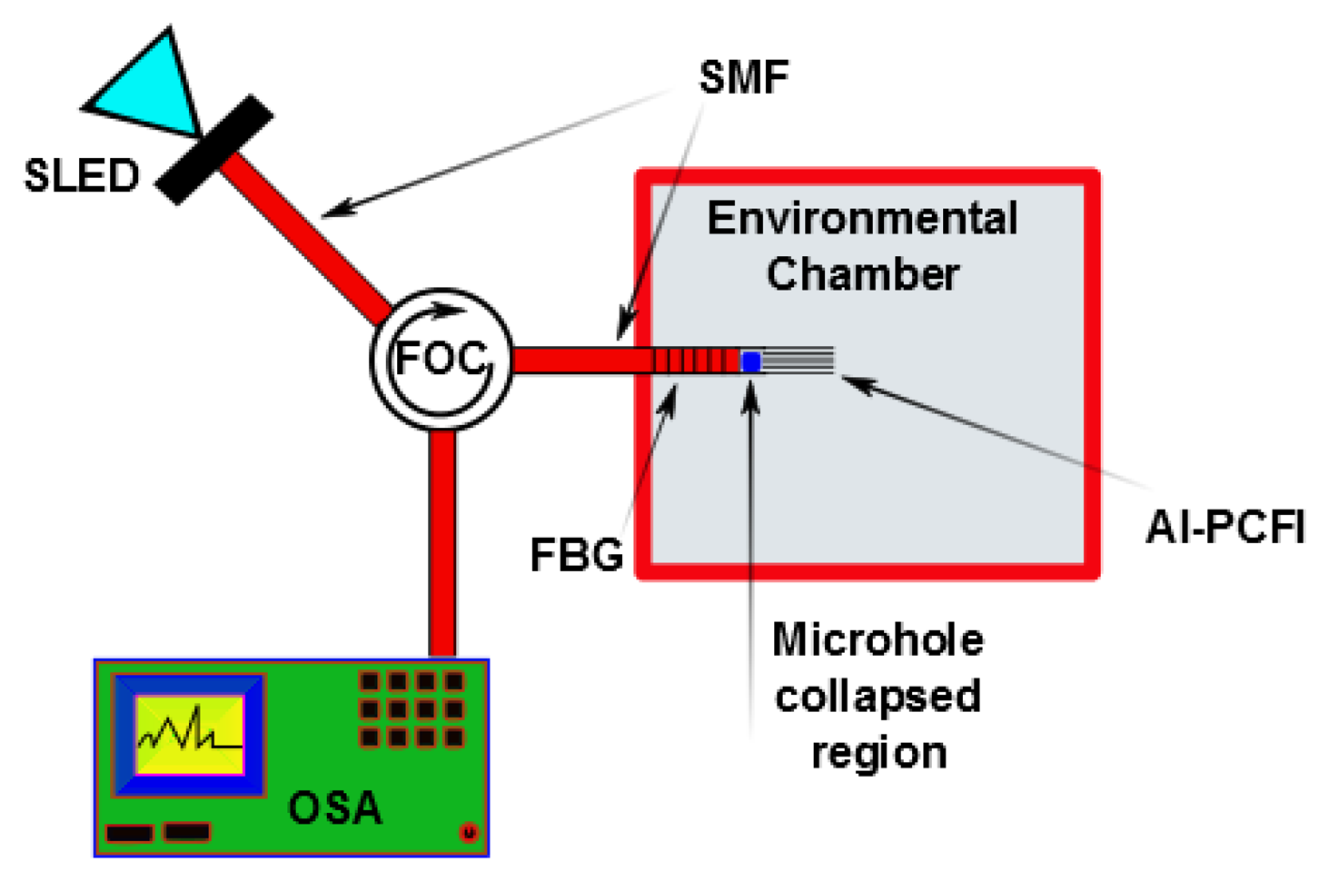
A fast sensor with a linear response has been developed by Gu [79] using a thin-core fiber modal interferometer with a fiber Bragg grating written in the interior of the interferometer. Poly (N-ethyl-4-vinylpyridinium chloride) and salt of poly-vinyl-sulfonic acid and sodium were used as the hydrophilic material. The FBG was used to compensate for changes in the temperature. The implementation of the photonic crystal fibre interferometer [100] with FBG and using agarose as the hydrophilic material was proposed by Mathew et al. [114]. Figure 7 illustrates the scheme of the proposed sensor. This sensor produced a variation in the detected optical power of over 7 dB for a RH range of 75% and had a low level of temperature-humidity crosstalk. Other sensors based on a LPFGs include: a Mach-Zehnder interferometer based on cascaded long-period gratings coated with a thin-film of hydro-gel [110]; a Michelson interferometer using a LPFG grating pair formed by coating a mirror at the distal end of the LPFG [104]; and an LPFG using a tailored layered polyimide coating on the grating region [111] were put into operation. The former detector only operated over a limited (60%–100%) RH range. However, the second and third sensors showed operability over a range of 20%–80% RH, which was wider than the range where the former one operated.
4.4. Evanescent Wave Humidity Sensors
The principle of operation of evanescent field humidity sensors (EFHS) is quite simple. Electromagnetic field propagating inside the core of a waveguide do not confined completely inside it [115]. The fraction of the field that is confined inside of the core of a waveguide is called either the guided wave or the guided mode. In the same time, the part of the field that propagates outside of the waveguide is called either the evanescent wave or the evanescent field. The guided field and the evanescent field are related by condition of continuity of electromagnetic field on the border between the core and the cladding. This means that the guided field will be affected by any changes that the evanescent field experiences. When some water molecules are absorbed into the hydrophilic material the refractive index of the hydrophilic material changes. If the evanescent field propagates inside of the hydrophilic material, this change will affect the evanescent field and can be detected as a change in the guided mode. One of the common way to detect the changes in the evanescent field is, for example, by using an interferometer [79].
Today, efforts to improve of the performance of EFHS are mainly focused on research into novel, more sensitive hydrophilic materials as, for example, mats of electro-spun nano-fiber [116], layer of di-ureasil xerogel containing lithium bits [76,77], titanium dioxide nano-particles [117] or thin film of silica sol-gel [118]. In addition, different ways to generate evanescent field were tested, as for example, hetero-core optical fibers [119], no-core fiber structures [120], sub-wavelength diameter fiber taper [90] and multi-modal fibres [121].
Fuke [122] has published the results of synthesis of Ag-polyaniline nano-composite for application in a fiber-based humidity sensor using wave absorption spectroscopy. The sensor has been tested and optimized by varying the size of silver particles and the cladding length. The sensor has been operate over the range of humidity 5%–95% RH. It has been shown that a reduction in the size of the deposited particles leads to a dramatic improvement in the sensor sensitivity and the speed of response. A similar effect has also been observed for acoustic sensors. However even after optimization, the sensor had relatively long response time of 30 s and a recovery time of 90 s.
A humidity sensor based on a multi-mode fiber taper coated with polyvinyl alcohol has been investigated by Li [91]. The principle of operation of this sensor was based on the interaction between the optical evanescent field and the coating along the taper waist. This sensor showed maximum sensitivity of 1.994 μW/% RH over the humidity range 30%–95% RH, fast response of 2 s and small temperature crosstalk.
Another interesting result has been published by Lui. In his experiments with regularly aligned nano-rods, Liu [123] has showed that a structure based on zinc oxide nano-rods radially grown on a silica fiber allows improved sensitivity of a sensor more than 50 times in comparison with the case of a fibre covered with disordered nano-particles of zinc oxide. The sensor showed good sensitivity over a wide range (10%–95% RH) of sensing.
4.5. Other Optical Humidity Sensors
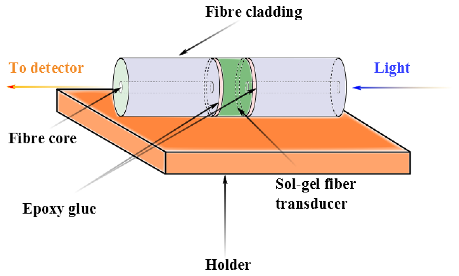
A new concept in optical-fiber humidity sensor called either the active fiber core optical sensor or AFCOS, has been presented by Tao [124]. In this sensor, the fiber core plays the role of a transducer (see the example in Figure 8).
This type of sensor is based on a technique for doping porous sol-gel optical fibers with chemical reagents (CoCl2). These sensors are sensitive down to very low humidity levels (2% RH) but are not useful for an environment with higher than 10% RH humidity.
A simple, inexpensive optode for relative humidity (RH) monitoring in air has been fabricated by Bedoya [82] using the water-sensitive luminescent dye. The optode was able to measure humidity in the range from 4% to 100% RH, but had a very long response time of 1.4 min. The stability of the sensor was verified over 2.5 years for weather monitoring and measuring the humidity level in food. The sensor showed good stability and had the ability to recover completely after been soaked.
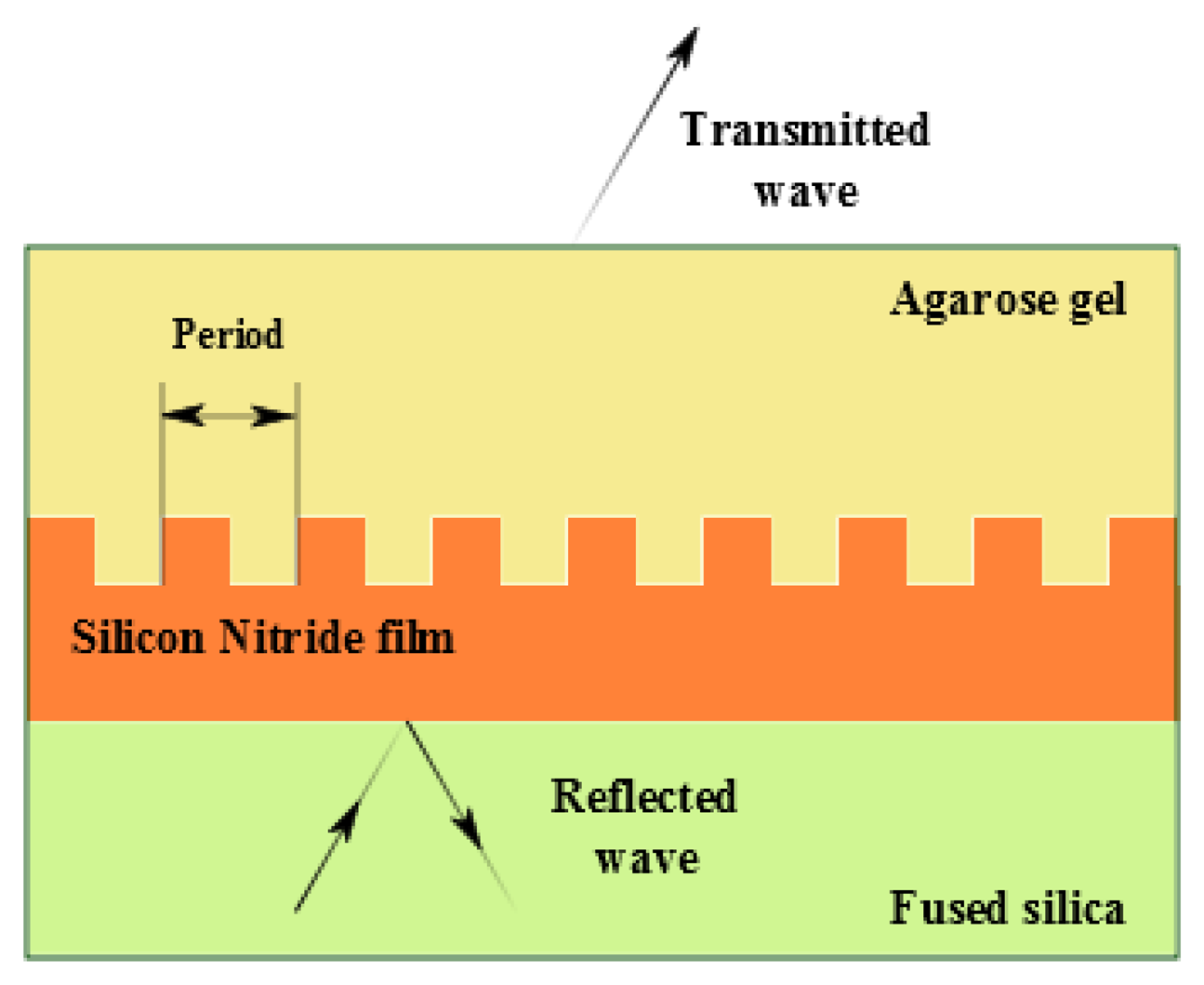
A non-fiber sensor has been developed by Lee and coworkers [125]. This sensor was based on changes in a guide-mode resonance using an agarose-gel transducer layer integrated with a periodic silicon-nitride film. The operation principle of the sensor is illustrated in Figure 9. The incident beam of light is phase matched to the periodic structure and is reflected along the layer of fused silica. The resonance wavelength changes when the hydrophilic material absorbs water. This change was used to detect humidity variations.
5. Conclusions
Today, the standard low-cost humidity sensors are the capacitance and resistance based electronic sensors. Significant advances have been made over the last ten years in addressing the limitations of these sensors and improving their ease of use. In particular, there has been progress in improving the speed of response to below 1 second and in developing sensors that are compatible with silicon technology. This compatibility has been exploited to allow integration with temperature and other sensors; generate an easy to use digital output; incorporate a heater which allows both the operation in atmosphere with the high humidity and either fast recovery from condensation or avoidance of it.
Today, a new generation of humidity sensing technology based on optical fibers is emerging. Humidity sensors based on the concept of the photonic crystal fiber are expected to be available soon. These sensors will be faster than the electronic humidity sensors that are available today. The current trends suggest that for many applications, electronic humidity sensors could soon either be replaced or complemented by sensors that are based on photonic crystals.
Furthermore, we highlight what we believe are two of the most significant achievements in the area of humidity sensing in the recent scientific literature. Polyvinyl alcohol (PVA) has emerged as a new and very promising material for humidity detection. This material allows fabrication of very fast and selective sensors with response times of less than one second. The second area which has seen significant advances is in the field of interferometric sensors. This novel sensor technology, presented by Gerald Farrell, Yuliya Semenova and Sunish Mathew from Dublin Institute of Technology, constitutes an important advance in sensing technology. It was demonstrated experimentally [99] that a simple design, using a laser diode as an interrogator is possible to use with this kind of sensors. Meanwhile, most of the sensors that are based on optical fibers require the use of a spectrum analyzer as the interrogator. The technology, which allows the use of low cost laser diodes as the interrogators, is expected to be attractive for industrial exploitation.
Today the first humidity sensors based on fiber optics are starting to appearing on the markets. We expect that the application of fiber-based sensors will grow exponentially throughout the next decade. Initially, optical humidity sensors will satisfy specific unfulfilled applications in the chemical industry, where humidity control would be beneficial but present electronic sensors cannot satisfy the need. There are applications in the chemical industry, where there is the need to monitor tanks with corrosive, flammable or explosive atmospheres, and where fiber optic humidity sensors, such as those based on the interferometric technique or fiber Bragg gratings could offer a unique solution. Another attractive feature of the fiber based technology is the relative ease of integrating centralized remote monitoring and control over a number of separate facilities related with the low cost and low weight of the optical fiber cable in comparison with a copper cable . An optical interrogation module can be designed to allow simultaneous interrogation of tens or even hundreds of sensors. This can be installed in a remote office allowing the operator to monitor a set of sensors covering an area of up to a few miles in radius. In addition, recent scientific advances should allow lower cost dedicated systems by avoiding the relatively high price of interrogation modules which are presently a significant disadvantage of fiber-based sensors.
Acknowledgments
This work was supported by West Midlands European Regional Development Fund (ERDF) project. Moreover, the authors would like to thank Sergei K. Turitsyn for support and fruitful discussions.
Author Contributions
All authors contributed extensively to the work presented in this paper. Stanislav Kolpakov wrote the paper and the topic about acoustic sensors. The topic about optical sensors was written by Stanislav Kolpakov and Chengbo Mou. Neil Gordon performed simulations and wrote the part about electronic sensors. Kaiming Zhou contributed in sections about acoustic and optical sensing. He also provided his suggestions and corrections during the preparation of the paper.
Conflicts of Interest
The authors declare no conflicts of interest.
References
- Tatara, T.; Tsuzaki, K. An apnea monitor using a rapid-response hygrometer. J. Clin. Monit. Comput. 1997, 13, 5–9. [Google Scholar]
- Lin, Y.C. Breath sensor based on reflective optical lensed fiber. Microw. Opt. Technol. Lett. 2013, 55, 450–454. [Google Scholar]
- Kastner, W.; Neugschwandtner, G.; Soucek, S.; Newmann, H.M. Communication systems for building automation and control. Proc. IEEE 2005, 93, 1178–1203. [Google Scholar]
- Laville, C.; Pellet, C. Interdigitated humidity sensors for a portable clinical microsystem. IEEE Trans. Biomed. Eng. 2002, 49, 1162–1167. [Google Scholar]
- Habib Ahsan, A.H.M.; Lange, C.F.; Moussa, W. Development of a Humidity Microsensor with Thermal Reset. Proceedings of the International Conference on MEMS, NANO and Smart Systems, Banff, AB, Canada, 20–23 July 2003; pp. 89–93.
- Chairperson Publications Board. Guide to Meteorological Instruments and Methods of Observation, 7th ed.; World Meteorological Organization: Geneva, Switzerland, 2008. [Google Scholar]
- Lazarus, N.; Fedder, G.K. Designing a robust high-speed CMOS-MEMS capacitive humidity sensor. J. Micromech. Microeng. 2012, 22, 085021. [Google Scholar]
- Mathew, J.; Semenova, Y.; Rajan, G.; Farrell, G. Humidity sensor based on a photonic crystal fibre interferometer. Electron. Lett. 2010, 46, 1341–1343. [Google Scholar]
- Favero, F.; Villatoro, J.; Pruneri, V. Microstructured optical fiber interferometric breathing sensor. J. Biomed. Opt. 2012, 17, 037006. [Google Scholar]
- Zheng, S.; Zhu, Y.; Krishnaswamy, S. Fiber humidity sensors with high sensitivity and selectivity based on interior nanofilm-coated photonic crystal fiber long-period gratings. Sens. Actuators B Chem. 2013, 176, 264–274. [Google Scholar]
- Cardenas-Sevilla, G.; Favero, F.; Villatoro, J. High-visibility photonic crystal fiber interferometer as multifunctional sensor. Sensors 2013, 13, 2349–2358. [Google Scholar]
- Matko, V.; Koprivnikar, J. Quartz sensor for water absorption measurement in glass-fiber resins. Instrum. Meas. IEEE Trans. 1998, 47, 1159–1162. [Google Scholar]
- Matko, V.; Donlagic, D. Sensor for High-Air-Humidity Measurement. Proceedings of the Conference on Precision Electromagnetic Measurements Digest, Braunschweig, Germany, 17–21 June 1996; pp. 351–353.
- Zhang, T.; Mubeen, S.; Myung, N.V.; Deshusses, M.A. Recent progress in carbon nanotube-based gas sensors. Nanotechnology 2008, 19, 332001. [Google Scholar]
- Li, H.; Zhang, J.; Tao, B.; Wan, L.; Gong, W. Investigation of capacitive humidity sensing behavior of silicon nanowires. Phys. E Low-Dimens. Syst. Nanostruct. 2009, 41, 600–604. [Google Scholar]
- Kauffman, D.R.; Star, A. Carbon nanotube gas and vapor sensors. Angew. Chem. Int. Ed. 2008, 47, 6550–6570. [Google Scholar]
- Yoo, K.P.; Lim, L.T.; Min, N.K.; Lee, M.J.; Lee, C.J.; Park, C.W. Novel resistive-type humidity sensor based on multiwall carbon nanotube/polyimide composite films. Sens. Actuators B Chem. 2010, 145, 120–125. [Google Scholar]
- Yeow, J.T.W.; She, J.P.M. Carbon nanotube-enhanced capillary condensation for a capacitive humidity sensor. Nanotechnology 2006, 17, 5441–5448. [Google Scholar]
- Steele, J.; Fitzpatrick, G.; Brett, M.J. Capacitive humidity sensors with high sensitivity and subsecond response times. IEEE Sens. J. 2007, 7, 955–956. [Google Scholar]
- Ahmad, Z.; Zafar, Q.; Sulaiman, K.; Akram, R.; Karimov, K.S. A humidity sensing organic-inorganic composite for environmental monitoring. Sensors 2013, 13, 3615–3624. [Google Scholar]
- Bi, H.; Yin, K.; Xie, X.; Ji, J.; Wan, S.; Sun, L.; Terrones, M.; Dresselhaus, M.S. Ultrahigh humidity sensitivity of graphene oxide. Sci. Rep. 2013. [Google Scholar] [CrossRef]
- Chen, W.P.; Zhao, Z.G.; Liu, X.W.; Zhang, Z.X.; Suo, C.G. A capacitive humidity sensor based on multi-wall carbon nanotubes (MWCNTs). Sensors 2009, 9, 7431–7444. [Google Scholar]
- Kang, U.; Wise, K. A high-speed capacitive humidity sensor with on-chip thermal reset. IEEE Trans. Electron Devices 2000, 47, 702–710. [Google Scholar]
- Kuo, L.S.; Huang, H.H.; Yang, C.H.; Chen, P.H. Real-time remote monitoring of temperature and humidity within a proton exchange membrane fuel cell using flexible sensors. Sensors 2011, 11, 8674–8684. [Google Scholar]
- Lee, C.Y.; Su, A.; Liu, Y.C.; Chan, P.C.; Lin, C.H. Sensor fabrication method for in situ temperature and humidity monitoring of light emitting diodes. Sensors 2010, 10, 3363–3372. [Google Scholar]
- Ma, R.H.; Wang, Y.H.; Lee, C.Y. Wireless remote weather monitoring system based on MEMS technologies. Sensors 2011, 11, 2715–2727. [Google Scholar]
- Nizhnik, O.; Higuchi, K.; Maenaka, K. A standard CMOS humidity sensor without post-processing. Sensors 2011, 11, 6197–6202. [Google Scholar]
- Nizhnik, O.; Higuchi, K.; Maenaka, K. Self-calibrated humidity sensor in CMOS without post-processing. Sensors 2012, 12, 226–232. [Google Scholar]
- Yang, M.Z.; Dai, C.L.; Lu, D.H. Polypyrrole porous micro humidity sensor integrated with a ring oscillator circuit on chip. Sensors 2010, 10, 10095–10104. [Google Scholar]
- Wagner, T.; Krotzky, S.; Weiss, A.; Sauerwald, T.; Kohl, C.D.; Roggenbuck, J.; Tiemann, M. A high temperature capacitive humidity sensor based on mesoporous silica. Sensors 2011, 11, 3135–3144. [Google Scholar]
- Wang, S.; Xia, G.; He, H.; Yi, K.; Shao, J.; Fan, Z. Structural and optical properties of nanostructured TiO2 thin films fabricated by glancing angle deposition. J. Alloy. Compd. 2007, 431, 287–291. [Google Scholar]
- Arshaka, K.; Twomey, K. Thin films of In2O3/SiO for humidity sensing applications. Sensors 2002, 2, 205–218. [Google Scholar]
- Arshaka, K.; Twomey, K.; Egan, D. A ceramic thick film humidity sensor based on MnZn ferrite. Sensors 2002, 2, 50–61. [Google Scholar]
- Kuang, Q.; Lao, C.; Wang, Z.L.; Xie, Z.; Zheng, L. High-sensitivity humidity sensor based on a single SnO2 nanowire. J. Am. Chem. Soc. 2007, 129, 6070–6071. [Google Scholar]
- Lee, S.P. Synthesis and characterization of carbon nitride films for micro humidity sensors. Sensors 2008, 8, 1508–1518. [Google Scholar]
- Huang, C.W.; Huang, Y.J.; Lu, S.S.; Lin, C.T. A fully integrated humidity sensor system-on-chip fabricated by micro-stamping technology. Sensors 2012, 12, 11592–11600. [Google Scholar]
- Rubinger, C.P.L.; Calado, H.D.R.; Rubinger, R.M.; Oliveira, H.; Donnici, C.L. Characterization of a sulfonated polycarbonate resistive humidity sensor. Sensors 2013, 13, 2023–2032. [Google Scholar]
- Yang, M.Z.; Dai, C.L.; Lin, W.Y. Fabrication and characterization of polyaniline/PVA humidity microsensors. Sensors 2011, 11, 8143–8151. [Google Scholar]
- Penza, M.; Anisimkin, V.I. Surface acoustic wave humidity sensor using polyvinyl-alcohol film. Sens. Actuators A Phys. 1999, 76, 162–166. [Google Scholar]
- Caliendo, C.; Verona, E.; Anisimkin, V.I. Surface acoustic wave humidity sensors: a comparison between different types of sensitive membrane. Smart Mater. Struct. 1997, 6, 707–715. [Google Scholar]
- Sauerbrey, G. The use of quartz oscillators for weighing thin layers and for microweighing (In German). Zeitschrift für Physik 1959, 155, 155–206. [Google Scholar]
- Sheng, L.; Chen, D.; Chen, Y. A surface acoustic wave humidity sensor with high sensitivity based on electrospun MWCNT/Nafion nanofiber films. Nanotechnology 2011, 22, 265504. [Google Scholar]
- Lv, X.; Li, Y.; Hong, L.; Luo, D.; Yang, M. A highly water-resistive humidity sensor based on silicon-containing polyelectrolytes prepared by one-pot method. Sens. Actuators B Chem. 2007, 124, 347–351. [Google Scholar]
- Li, Y.; Li, P.; Yang, M.; Lei, S.; Chen, Y.; Guo, X. A surface acoustic wave humidity sensor based on electrosprayed silicon-containing polyelectrolyte. Sens. Actuators B Chem. 2010, 145, 516–520. [Google Scholar]
- Penza, M.; Cassano, G. Relative humidity sensing by PVA-coated dual resonator SAW oscillator. Sens Actuators B Chem. 2000, 68, 300–306. [Google Scholar]
- Braga, E.; Nakano, A.; da Cunha, M. A SAW Resonator Sensor System Employed in Humidity Measurements. Proceedings of the International Microwave and Optoelectronics Conference (SBMO/IEEE MTT-S, APS and LEOS-IMOC'99), Rio de Janeiro, Brazil, 9–12 August 1999; Volume 1, pp. 342–345.
- Kawalec, A.; Pasternak, M. A new high-frequency surface acoustic wave sensor for humidity measurement. Instrum. Meas. IEEE Trans. 2008, 57, 2019–2023. [Google Scholar]
- Kawalec, A.; Jasek, K.; Pasternak, M. Measurements results of SAW humidity sensor with nafion layer. Eur. Phys. J. Spec. Top. 2008, 154, 123–126. [Google Scholar]
- Rimeika, R.; Ciplys, D.; Poderys, V.; Rotomskis, R.; Shur, M. Humidity Sensor Using Leaky Surface Acoustic Waves in YX-LiTaO3 with Nanostructured Porphyrin Film. Proceedings of the 2009 IEEE on Sensors, Christchurch, New Zealand, 25–28 October 2009; pp. 1753–1757.
- Zhu, Y.; Yuan, H.; Xu, J.; Xu, P.; Pan, Q. Highly stable and sensitive humidity sensors based on quartz crystal microbalance coated with hexagonal lamelliform monodisperse mesoporous silica SBA-15 thin film. Sens. Actuators B Chem. 2010, 144, 164–169. [Google Scholar]
- Zhou, X.; Jiang, T.; Zhang, J.; Wang, X.; Zhu, Z. Humidity sensor based on quartz tuning fork coated with solgel-derived nanocrystalline zinc oxide thin film. Sens. Actuators B Chem. 2007, 123, 299–305. [Google Scholar]
- Shinbo, K.; Otuki, S.; Kanbayashi, Y.; Ohdaira, Y.; Baba, A.; Kato, K.; Kaneko, F.; Miyadera, N. A hybrid humidity sensor using optical waveguides on a quartz crystal microbalance. Thin Solid Films 2009, 518, 629–633. [Google Scholar]
- Su, P.G.; Sun, Y.L.; Lin, C.C. A low humidity sensor made of quartz crystal microbalance coated with multi-walled carbon nanotubes/Nafion composite material films. Sens. Actuators B Chem. 2006, 115, 338–343. [Google Scholar]
- Su, P.G.; Chang, Y.P. Low-humidity sensor based on a quartz-crystal microbalance coated with polypyrrole/Ag/TiO2 nanoparticles composite thin films. Sens. Actuators B Chem. 2008, 129, 915–920. [Google Scholar]
- Wang, X.; Ding, B.; Yu, J.; Wang, M.; Pan, F. A highly sensitive humidity sensor based on a nanofibrous membrane coated quartz crystal microbalance. Nanotechnology 2010, 21, 055502. [Google Scholar]
- Wang, X.H.; Ding, Y.F.; Zhang, J.; Zhu, Z.Q.; You, S.Z.; Chen, S.Q.; Zhu, J. Humidity sensitive properties of ZnO nanotetrapods investigated by a quartz crystal microbalance. Sens. Actuators B Chem. 2006, 115, 421–427. [Google Scholar]
- Zhang, Y.; Yu, K.; Xu, R.; Jiang, D.; Luo, L.; Zhu, Z. Quartz crystal microbalance coated with carbon nanotube films used as humidity sensor. Sens. Actuators A Phys. 2005, 120, 142–146. [Google Scholar]
- Zhang, Y.; Yu, K.; Ouyang, S.; Luo, L.; Hu, H.; Zhang, Q.; Zhu, Z. Detection of humidity based on quartz crystal microbalance coated with ZnO nanostructure films. Phys. B Condens. Matter. 2005, 368, 94–99. [Google Scholar]
- Zhou, X.; Zhang, J.; Jiang, T.; Wang, X.; Zhu, Z. Humidity detection by nanostructured ZnO: A wireless quartz crystal microbalance investigation. Sens. Actuators A Phys. 2007, 135, 209–214. [Google Scholar]
- Fu, J.; Ayazi, F. Dual-Mode Piezo-on-Silicon Resonant Temperature and Humidity Sensor for Portable Air Quality Monitoring Systems. Proceedings of the 2010 IEEE on Sensors, Kona, HI, USA, 1–4 November 2010; pp. 2131–2135.
- Qiu, X.; Wang, Z.; Zhu, J.; Oiler, J.; Tang, R.; Yu, C.; Yu, H. The effects of relative humidity and reducing gases on the temperature coefficient of resonant frequency of ZnO based film bulk acoustic wave resonator. IEEE Trans. Ultrason. Ferroelectr. Freq. Control 2010, 57, 1902–1905. [Google Scholar]
- Tashtoush, N.M.; Cheeke, J.D.N.; Eddy, N. Surface acoustic wave humidity sensor based on a thin PolyXIO film. Sens. Actuators B Chem. 1998, 49, 516–520. [Google Scholar]
- Li, Y.; Yang, M.J.; Ling, M.F.; Zhu, Y.H. Surface acoustic wave humidity sensors based on poly(p-diethynylbenzene) and sodium poly sulfone sulfonate. Sens. Actuators B Chem. 2007, 122, 560–563. [Google Scholar]
- Penza, M.; Cassano, G.; Sergi, A.; Sterzo, C.L.; Russo, M.V. SAW chemical sensing using poly-ynes and organometallic polymer films. Sens. Actuators B Chem. 2001, 81, 88–98. [Google Scholar]
- Levit, N.; Pestov, D.; Tepper, G. High surface area polymer coatings for SAW-based chemical sensor applications. Sens. Actuators B Chem. 2002, 82, 241–249. [Google Scholar]
- Li, Y.; Li, P.; Yanga, M.; Lei, S.; Chenb, Y.; Guoc, X. A surface acoustic wave humidity sensor based on electrosprayed silicon-containing polyelectrolyte. Sens. Actuators B Chem. 2010, 145, 516–520. [Google Scholar]
- Shen, C.Y.; Huang, C.P.; Huang, W. Gas-detecting properties of surface acoustic wave ammonia sensors. Sens. Actuators B Chem. 2004, 101, 1–7. [Google Scholar]
- Sarkar, S.; Levit, N.; Tepper, G. Deposition of polymer coatings onto SAW resonators using AC electrospray. Sens. Actuators B Chem. 2006, 114, 756–761. [Google Scholar]
- Buvailo, A.; Xing, Y.; Hines, J.; Borguet, E. Thin polymer film based rapid surface acoustic wave humidity sensors. Sens. Actuators B Chem. 2011, 156, 444–449. [Google Scholar]
- Consales, M.; Buosciolo, A.; Cutolo, A.; Breglio, G.; Irace, A.; Buontempo, S.; Petagna, P.; Giordano, M.; Cusano, A. Fiber optic humidity sensors for high-energy physics applications at CERN. Sens. Actuators B Chem. 2011, 159, 66–74. [Google Scholar]
- Garcia-Diego, F.J.; Fernandez-Navajas, A.; Beltran, P.; Merello, P. Study of the effect of the strategy of heating on the mudejar church of Santa Maria in Ateca (Spain) for preventive conservation of the altarpiece surroundings. Sensors 2013, 13, 11407–11423. [Google Scholar]
- Lin, Y.C. Breath sensor based on reflective optical lensed fiber. Microw. Opt. Technol. Lett. 2013, 55, 450–454. [Google Scholar]
- Xu, L.; Fanguy, J.C.; Soni, K.; Tao, S. Optical fiber humidity sensor based on evanescent-wavescattering. Opt. Lett. 2004. [Google Scholar]
- Yeo, T.; Sun, T.; Grattan, K.; Parry, D.; Lade, R.; Powell, B. Polymer-coated fiber Bragg grating for relative humidity sensing. IEEE Sens. J. 2005, 5, 1082–1089. [Google Scholar]
- Huang, X.; Sheng, D.; Cen, K.; Zhou, H. Low-cost relative humidity sensor based on thermoplastic polyimide-coated fiber Bragg grating. Sens. Actuators B Chem. 2007, 127, 518–524. [Google Scholar]
- Barbosa, P.C.; Silva, M.M.; Smith, M.J.; Gonçalves, A.; Fortunato, E.; Nunes, S.C.; de Zea Bermudez, V. Di-ureasil xerogels containing lithium bis(trifluoromethanesulfonyl)imide for application in solid-state electrochromic devices. Electrochim. Acta 2009, 54, 1002–1009. [Google Scholar]
- Correia, S.F.; Antunes, P.; Pecoraro, E.; Lima, P.P.; Varum, H.; Carlos, L.D.; Ferreira, R.A.; Andre, P.S. Optical fiber relative humidity sensor based on a FBG with a di-ureasil coating. Sensors 2012, 12, 8847–8860. [Google Scholar]
- Berruti, G.; Consales, M.; Giordano, M.; Sansone, L.; Petagna, P.; Buontempo, S.; Breglio, G.; Cusano, A. Radiation hard humidity sensors for high energy physics applications using polyimide-coated fiber Bragg gratings sensors. Sens. Actuators B Chem. 2013, 177, 94–102. [Google Scholar]
- Gu, B.; Yin, M.; Zhang, A.P.; Qian, J.; He, S. Optical fiber relative humidity sensor based on FBG incorporated thin-core fiber modal interferometer. Opt. Express 2011, 19, 4140–4146. [Google Scholar]
- Mathew, J.; Semenova, Y.; Farrell, G. Relative humidity sensor based on an agarose-infiltrated photonic crystal fiber interferometer. IEEE J. Sel. Top. Quantum Electron. 2012, 18, 1553–1559. [Google Scholar]
- Chen, L.H.; Li, T.; Chan, C.C.; Menon, R.; Balamurali, P.; Shaillender, M.; Neu, B.; Ang, X.M.; Zu, P.; Wong, W.C.; et al. Chitosan based fiber-optic Fabry-Perot humidity sensor. Sens. Actuators B Chem. 2012, 169, 167–172. [Google Scholar]
- Bedoya, M.; Dez, M.T.; Moreno-Bondi, M.C.; Orellana, G. Humidity sensing with a luminescent Ru(II) complex and phase-sensitive detection. Sens. Actuators B Chem. 2006, 113, 573–581. [Google Scholar]
- Aneesh, R.; Khijwania, S.K. Zinc oxide nanoparticle-doped nanoporous solgel fiber as a humidity sensor with enhanced sensitivity and large linear dynamic range. Appl. Opt. 2013, 52, 5493–5499. [Google Scholar]
- Corres, J.; Matias, I.; Hernaez, M.; Bravo, J.; Arregui, F. Optical fiber humidity sensors using nanostructured coatings of SiO2 nanoparticles. IEEE Sens. J. 2008, 8, 281–285. [Google Scholar]
- Estella, J.; de Vicente, P.; Echeverra, J.C.; Garrido, J.J. A fibre-optic humidity sensor based on a porous silica xerogel film as the sensing element. Sens. Actuators B Chem. 2010, 149, 122–128. [Google Scholar]
- Noor, M.Y.M.; Khalili, N.; Skinner, I.; Peng, G.D. Optical relative humidity sensor based on a hollow core-photonic bandgap fiber. Meas. Sci. Technol. 2012, 23, 085103. [Google Scholar]
- Rivero, P.J.; Urrutia, A.; Goicoechea, J.; Arregui, F. Optical fiber humidity sensors based on Localized Surface Plasmon Resonance (LSPR) and Lossy-mode resonance (LMR) in overlays loaded with silver nanoparticles. Sens. Actuators B Chem. 2012, 173, 244–249. [Google Scholar]
- Wang, B.; Zhang, F.; Pang, F.; Wang, T. An Optical Fiber Humidity Sensor Based on Optical Absorption. Proceedings of the 2011 Asia Communications and Photonics Conference and Exhibition (ACP 2011), Shanghai, China, 13–16 September 2011; pp. 1–6.
- Mathew, J.; Semenova, Y.; Farrell, G. A fiber bend based humidity sensor with a wide linear range and fast measurement speed. Sens. Actuators A Phys. 2012, 174, 47–51. [Google Scholar]
- Zhang, L.; Gu, F.; Lou, J.; Yin, X.; Tong, L. Fast detection of humidity with a subwavelength-diameter fiber taper coated with gelatin film. Opt. Express 2008, 16, 13349–13353. [Google Scholar]
- Li, T.; Dong, X.; Chan, C.C.; Zhao, C.L.; Zu, P. Humidity sensor based on a multimode-fiber taper coated With polyvinyl alcohol interacting with a fiber bragg grating. IEEE Sens. J. 2012, 12, 2205–2208. [Google Scholar]
- Miao, Y.; Liu, B.; Zhang, H.; Li, Y.; Zhou, H.; Sun, H.; Zhang, W.; Zhao, Q. Relative humidity sensor based on tilted fiber bragg grating with polyvinyl alcohol coating. IEEE Photonics Technol. Lett. 2009, 21, 441–443. [Google Scholar]
- Yeo, T.L.; Sun, T.; Grattan, K.T.V.; Parry, D.; Lade, R.; Powell, B.D. Characterisation of a polymer-coated fibre Bragg grating sensor for relative humidity sensing. Sens. Actuators B Chem. 2005, 110, 148–156. [Google Scholar]
- Wong, W.C.; Chan, C.C.; Chen, L.H.; Li, T.; Lee, K.X.; Leong, K.C. Polyvinyl alcohol coated photonic crystal optical fiber sensor for humidity measurement. Sens. Actuators B Chem. 2012, 174, 563–569. [Google Scholar]
- Zhang, C.; Zhang, W.; Webb, D.J.; Peng, G.D. Optical fibre temperature and humidity sensor. Electron. Lett. 2010, 46, 643. [Google Scholar]
- Viegas, D.; Goicoechea, J.; Corres, J.M.; Santos, J.L.; Ferreira, L.A.; Araújo, F.M.; Matias, I.R. A fibre optic humidity sensor based on a long-period fibre grating coated with a thin film of SiO2 nanospheres. Meas. Sci. Technol. 2009, 20, 034002. [Google Scholar]
- Favero, F.C.; Villatoro, J.; Pruneri, V. Microstructured optical fiber interferometric breathing sensor. J. Biomed. Opt. 2012, 17, 037006. [Google Scholar]
- Chen, L.H.; Chan, C.C.; Li, T.; Shaillender, M.; Neu, B.; Balamurali, P.; Menon, R.; Zu, P.; Ang, X.M.; Wong, W.C.; et al. Chitosan-coated polarization maintaining relative humidity measurement. IEEE J. Sel. Top. Quantum Electron. 2012, 18, 1597–1604. [Google Scholar]
- Mathew, J.; Semenova, Y.; Farrell, G. A Miniature Optical Humidity Sensor. Proceedings of the 2011 IEEE Sensors Proceedings, Limerick, Ireland, 28–31 October 2011; pp. 2030–2033.
- Mathew, J.; Semenova, Y.; Rajan, G.; Farrell, G. Humidity sensor based on photonic crystal fibre interferometer. Electron. Lett. 2010, 46, 1341. [Google Scholar]
- Liang, H.; Jin, Y.; Wang, J.; Dong, X.; Street, X.; Higher, X.; Zone, E. Relative humidity sensor based on polarization maintainig fiber. Microw. Opt. Technol. Lett. 2012, 54, 2364–2366. [Google Scholar]
- Ivanov, O.; Nikitov, S.; Gulyaev, Y. Cladding modes of optical fibers: properties and applications. Phys.-Uspekhi 2006, 49, 167–191. [Google Scholar]
- Vasil'ev, S.A.; Dianov, E.M.; Medvedkov, O.I.; Protopopov, V.N.; Costantini, D.M.; Iocco, A.; Limberger, H.G.; Salathe, R.P. Properties of the cladding modes of an optical fibre excited by refractive-index gratings. Quantum Electron. 1999, 29, 65. [Google Scholar]
- Alwis, L.; Sun, T.; Grattan, K.T.V. Fibre optic long period grating-based humidity sensor probe using a Michelson interferometric arrangement. Sens. Actuators B Chem. 2013, 178, 694–699. [Google Scholar]
- Erdogan, T. Cladding-mode resonances in short- and long-period fiber grating filters. J. Opt. Soc. Am. A 1997, 14, 1760–1773. [Google Scholar]
- Fu, M.; Lin, G.; Liu, W.; Wu, C. Fiber-optic humidity sensor based on an air-gap long period fiber grating. Opt. Rev. 2011, 18, 93–95. [Google Scholar]
- Konstantaki, M.; Pissadakis, S.; Pispas, S.; Madamopoulos, N.; Vainos, N. Optical fiber long-period grating humidity sensor with poly(ethylene oxide)/cobalt chloride coating. Appl. Opt. 2006, 45, 4567–4571. [Google Scholar]
- Smietana, M.; Korwin-Pawlowski, M.L.; Bock, W.J.; Pickrell, G.R.; Szmidt, J. Refractive index sensing of fiber optic long-period grating structures coated with a plasma deposited diamond-like carbon thin film. Meas. Sci. Technol. 2008, 19, 085301. [Google Scholar]
- Wang, L.; Liu, Y.; Zhang, M.; Tu, D.; Mao, X.; Liao, Y. A relative humidity sensor using a hydrogel-coated long period grating. Meas. Sci. Technol. 2007, 18, 3131–3134. [Google Scholar]
- Yu, X.; Childs, P.; Zhang, M.; Liao, Y.; Ju, J.; Jin, W. Relative humidity sensor based on cascaded long-period gratings with hydrogel coatings and fourier demodulation. Photonics Technol. Lett. IEEE 2009, 21, 1828–1830. [Google Scholar]
- Alwis, L.; Sun, T.; Grattan, K.T.V. Analysis of polyimide-coated optical fiber long-period grating-based relative humidity sensor. IEEE Sens. J. 2013, 13, 767–771. [Google Scholar]
- Venugopalan, T.; Sun, T.; Grattan, K. Long period grating-based humidity sensor for potential structural health monitoring. Sens. Actuators A Phys. 2008, 148, 57–62. [Google Scholar]
- Viegas, D.; Goicoechea, J.; Santos, J.L.; Araújo, F.M.; Ferreira, L.A.; Arregui, F.J.; Matias, I.R. Sensitivity improvement of a humidity sensor based on silica nanospheres on a long-period fiber grating. Sensors 2009, 9, 519–527. [Google Scholar]
- Mathew, J.; Semenova, Y.; Farrell, G. Fiber optic hybrid device for simultaneous measurement of humidity and temperature. IEEE Sens. J. 2013, 13, 1632–1636. [Google Scholar]
- Marcuse, D. Theory of Dielectric Optical Waveguides, 2nd ed.; Academic Press: Boston, MA, USA, 1991. [Google Scholar]
- Urrutia, A.; Goicoechea, J.; Rivero, P.J.; Matías, I.R.; Arregui, F.J. Electrospun nanofiber mats for evanescent optical fiber sensors. Sens. Actuators B Chem. 2013, 176, 569–576. [Google Scholar]
- Aneesh, R.; Khijwania, S.K. Titanium dioxide nanoparticle based optical fiber humidity sensor with linear response and enhanced sensitivity. Appl. Opt. 2012, 51, 2164–2171. [Google Scholar]
- Zhao, Z.; Duan, Y. A low cost fiber-optic humidity sensor based on silica sol-gel film. Sens. Actuators B Chem. 2011, 160, 1340–1345. [Google Scholar]
- Akita, S.; Sasaki, H.; Watanabe, K.; Seki, A. A humidity sensor based on a hetero-core optical fiber. Sens. Actuators B Chem. 2010, 147, 385–391. [Google Scholar]
- Xia, L.; Li, L.; Li, W.; Kou, T.; Liu, D. Novel optical fiber humidity sensor based on a no-core fiber structure. Sens. Actuators A Phys. 2013, 190, 1–5. [Google Scholar]
- Zhao, Y.; Jin, Y.; Liang, H. All-Fiber-Optic Sensor for Relative Humidity Measurement. Proceedings of the 2011 International Conference on Electronics and Optoelectronics (ICEOE), Dalian, China, 29–31 July 2011; pp. 83–86.
- Fuke, M.V.; Kanitkar, P.; Kulkarni, M.; Kale, B.B.; Aiyer, R.C. Effect of particle size variation of Ag nanoparticles in Polyaniline composite on humidity sensing. Talanta 2010, 81, 320–326. [Google Scholar]
- Liu, Y.; Zhang, Y.; Lei, H.; Song, J.; Chen, H.; Li, B. Growth of well-arrayed ZnO nanorods on thinned silica fiber and application for humidity sensing. Opt. Express 2012, 20, 19404–19411. [Google Scholar]
- Tao, S.; Winstead, C.; Jindal, R.; Singh, J. Optical-fiber sensor using tailored porous sol-gel fiber core. IEEE Sens. J. 2004, 4, 322–328. [Google Scholar]
- Lee, K.; Wawro, D.; Priambodo, P.; Magnusson, R. Agarose-gel based guided-mode resonance humidity sensor. IEEE Sens. J. 2007, 7, 409–414. [Google Scholar]


| Sensor | Type | Response, s | Range, %RH | Hysteresis, % | ||
|---|---|---|---|---|---|---|
| Inc | Dec | min | max | |||
| SHT15 Polymer | C | 8 | 8 | 0 | 100 | 2 |
| DHT22 | C | NA | NA | 0 | 100 | 2 |
| HR202 | R | 10 | 10 | 20 | 95 | 1 |
| DHT11 | R | 10 | 10 | 20 | 90 | 4 |
| HMT330 1 | Electronic | 8 | 17 | 0 | 100 | 1 |
| HMT330 2 | Electronic | 20 | 50 | 0 | 100 | 1 |
| HMT330 3 | Electronic | 40 | 60 | 0 | 100 | 1 |
| HC2-C | Electronic | 15 | NA | 0 | 100 | NA |
| Fluke 971 | Electronic | 60 | NA | 5 | 95 | NA |
1.With grid filter;2.With steel netting filter;3.With sintered filter.
| Sensor | Type | Response, s | Range, %RH | Hysteresis, % | Ref. | ||
|---|---|---|---|---|---|---|---|
| Inc | Dec | min | max | ||||
| Composite (PEPC + NiPc + Cu2O) | C | 13 | 15 | 40 | 100 | 13 | [20] |
| Graphene oxide film | C | 10.5 | 41 | 15 | 95 | 5 | [21] |
| MWCNTs | C | 45 | 15 | 11 | 97 | NA | [22] |
| Polyimide film | C | 1 | 1 | 30 | 90 | 2 | [23] |
| 3 μm polyimide film on parylene on silicon | C | 1 | 1 | 30 | 90 | 2 | [24] |
| Polyimide film | C | 1.7 | 2.3 | 30 | 100 | NA | [25] |
| Polyimide film | C | NA | NA | 50 | 90 | NA | [26] |
| Standard CMOS polymer film | C | 70 | 70 | 10 | 95 | 5.5 | [27] |
| Standard CMOS polymer film | C | 70 | 70 | 10 | 95 | 3.1 | [28] |
| Polypyrrole | C | NA | NA | 25 | 95 | small | [29] |
| Mesoporous silica | C | NA | NA | 0 | 50 | NA | [30] |
| Capacitive-dependent crystal | C | 0.1 | 0.1 | 20 | 98 | 0.3 | [12,13] |
| Sensor | Type | Response, s | Range, %RH | Hysteresis, % | Ref. | ||
|---|---|---|---|---|---|---|---|
| Inc | Dec | min | max | ||||
| In2O3/SiO | R | NA | NA | 40 | 90 | NA | [32] |
| MnZn Ferrite | R | 17 | 25 | 30 | 90 | 0.97 | [33] |
| Fe-Al-polyaniline on CMOS | R | NA | NA | 32 | 55 | NA | [36] |
| SnO2 nanowire | R | 120–170 | 20–60 | 5 | 85 | NA | [34] |
| CNx deposited by RF sputtering | R | 150 | 175 | 5 | 95 | 3 | [35] |
| Sulfonated Polycarbonate | R | NA | NA | 11 | 90 | 4 | [37] |
| Polyaniline/PVA | R | NA | NA | 25 | 85 | NA | [38] |
| MWCNT/polyimide composite film | R | NA | NA | 10 | 95 | NA | [17] |
| Sensor | f | Sensitivity | Response | PH (%) | Ref. | |
|---|---|---|---|---|---|---|
| (MHz) | (ppm7/%RH) | Time (s) | min | max | ||
| MWCNT/Nafion nanofiber film 1 | ∼500 | 885.2 | 10 | 10 | 80 | [42] |
| APTS-P 1 [43] | 433 | 15 | 10 | 10 | 100 | [44] |
| PVA-coated dual resonator 1 | ∼468 | 11–395 | 1,800 | 20 | 80 | [45] |
| Cellulose acetate film 1 | 302 | 3.31 | NA | 10 | 80 | [46] |
| Nafion layer 1 | ∼302 | 2.75 | ≤20 | 10 | 100 | [47,48] |
| NPF-LSAW 1 | 60–110 | 0–6 6 | 0.25 | 10 | 90 | [49] |
| Monodisperse mesoporous silica 1 | 10 | 250–720 | 10 | 10 | 100 | [50] |
| Nanocrystalline Zn oxide 2 | 0.032 | 1.1597 | ≤150 | 10 | 100 | [51] |
| Fluorinated polyimides 3 | 5 | 2 | 300 | 15 | 85 | [52] |
| Nano-tubes/Nafion composite 3 | 9 | 0.1123 5 | 100 | 23.4 5 | 3,030.5 4 | [53] |
| Polypyrrole AgTiO2 nano-part. 3 | 10 | 0.0246 5 | 12 | 0 5 | 10,000 5 | [54] |
| Nanofibrous membrane 3 | 5 | 0.1–10 | 80–150 | 20 | 95 | [55] |
| ZnO nano-tetrapods 3 | 10 | 0–3.3 | NA | 30 | 90 | [56] |
| Carbon nano-tube film 3 | 25 | ≤4 | 60/70 8 | 5 | 97 | [57] |
| ZnO nanostructure film 3 | 25 | 0.26 | 90/120 8 | 5 | 97 | [58] |
| Nanostructured ZnO 3 | 10 | ≤1 | NA | 20 | 90 | [59] |
| ZnO on silicon base 4 | 35/86 | 400/16 | ≤25 | 20 | 92 | [60] |
| ZnO-FBAR 4 | 1,430 | 1.4 | NA | 25 | 85 | [61] |
1.SAW configuration;2.Quartz tuning fork;3.Quartz crystal microbalance humidity sensors;4.Bulk humidity sensors;5.In Hz/ppmv;6.dB/PH(%);7.Parts per million;8.Response/recovery time.
| Sensor | Linearity | Hysteresis 5 | Ref. |
|---|---|---|---|
| MWCNT/Nafion nanofiber film 1 | Linear between 10% and 75% | ≤10% | [42] |
| APTS-P 1 [43] | Linear | NA | [44] |
| PVA-coated dual resonator SAW 1 | Non linear | NA | [45] |
| Cellulose acetate film 1 | Linear between 10% and 60% | ≤7% | [46] |
| Nafion layer 1 | Linear between 10% and 60% | ≤12% | [47,48] |
| NPF-LSAW 1 | Non linear | NA | [49] |
| Monodisperse mesoporous silica 1 | Linear between 0% and 80% | ≤5 | [50] |
| Nanocrystalline Zn oxide 2 | Linear between 40% and 100% | NA | [51] |
| Fluorinated polyimides 3 | Non linear | NA | [52] |
| Carbon nano-tubes/Nafion composite 3 | Linear | NA | [53] |
| Polypyrrole AgTiO2 nano-particles 3 | Linear | NA | [54] |
| Nanofibrous membrane 3 | Exponential between 20% and 95% | NA | [55] |
| ZnO nano-tetrapods 3 | Non linear | NA | [56] |
| Carbon nano-tube film 3 | Linear | NA | [57] |
| ZnO nanostructure film 3 | Linear | NA | [58] |
| Nanostructured ZnO 3 | Non linear | NA | [59] |
| ZnO on silicon base 4 | Non linear | NA | [60] |
| ZnO-FBAR 4 | Non linear | NA | [61] |
1.SAW configuration;2.Quartz tuning fork;3.Quartz crystal microbalance humidity sensors;4.Bulk humidity sensors;5.The width of hysteresis in relation to whole measured interval.
| Sensor | Accuracy | Response, s | Range, %RH | |
|---|---|---|---|---|
| min | max | |||
| Nanosonic Inc. | 6% at 20 °C | 0.1 | 0 | 100 |
| O-eland FBG-based | 4.5% | fast | 10 | 100 |
| Sensor | Sensitivity | Response, s | Range PH (%) | Ref. | ||
|---|---|---|---|---|---|---|
| Inc | Dec | min | max | |||
| ZnO nanoparticles in solgel 1 | 0.0103 dB/%RH | 0.86 | 0.54 | 5 | 95 | [83] |
| SiO2 Nanoparticles 1 | 0.3 dB/%RH | 0.15 | 0.1 | 40 | 98 | [84] |
| Silica xerogel film 1 | 7.9 × 10 −2 nm−1 · % −1 | 10 | 120 | 4 | 100 | [85] |
| Hollow core fiber 1 | 3.02 mV/1%RH | 60 | NA | 0 | 90 | [86] |
| Surface Plasmon Resonance 1 | 0.943 nm per RH% | <0.5 | NA | 5 | 95 | [87] |
| CoCl2 into a PVA composite 1 | 0.5 dB/%RH | 120 | NA | 25 | 65 | [88] |
| Di-ureasil coated FBG 2 | 22.2 pm/%RH | 600 | NA | 15 | 95 | [77] |
| Bent single mode optical fiber 2 | <0.1 dB/%RH | 0.05 | NA | 25 | 90 | [89] |
| Gelatin film 2 | <0.1 dB/%RH | 0.07 | NA | 9 | 94 | [90] |
| Polyimide-coated FBG 3 | −0.000266 V/%RH | 5 | NA | 11 | 98 | [75] |
| PVA coated FBG 3 | 1.994 μW/%RH | 2 | NA | 30 | 95 | [91] |
| Tilted FBG with PVA 3 | 14.947 dBm/%RH | 2 | NA | 20 | 98 | [92] |
| Polyimide coated FBG 3 | 5.6 pm/%RH | 2,700 | NA | 20 | 98 | [93] |
| PVA 4 | 0.60 nm/%RH | 3 × 10⁻⁴ | 5 × 10⁻⁴ | 30 | 90 | [94] |
| FBG in a polymer fibre | 35.2 pm/%RH | 1,800 | NA | 50 | 95 | [95] |
| Luminescent Ru(II) complex | NA | <90 | NA | 4 | 100 | [82] |
| SiO2 nanospheres 5 | 0.2 nm/%RH | <0.02 | NA | 20 | 80 | [96] |
1.Absorption measurements;2.Evanescent wave;3.Strain;4.Interferometric;5.LPFG.
| Sensor | Linearity | Hysteresis6 | Ref. |
|---|---|---|---|
| ZnO nanoparticles in solgel 1 | Linear | NA | [83] |
| SiO2 Nanoparticles 1 | Linear 40%–98% | 0.25% | [84] |
| Silica xerogel film 1 | Linear 0%–60% | NA | [85] |
| Hollow core fiber 1 | Linear | NA | [86] |
| Surface Plasmon Resonance 1 | Linear | NA | [87] |
| CoCl2 into a PVA composite 1 | Non linear | <3% | [88] |
| Di-ureasil coated FBG 2 | Non linear | NA | [77] |
| Bent single mode optical fiber 2 | Linear 25%–90% | NA | [89] |
| Gelatin film 2 | Non linear | NA | [90] |
| Polyimide-coated FBG 3 | Linear | NA | [75] |
| PVA coated FBG 3 | Non linear | <4% | [91] |
| Tilted FBG with PVA 3 | Linear 20%–80% | <10% | [92] |
| Polyimide coated FBG 3 | Linear | <5% | [93] |
| PVA 4 | Non linear | 15% | [94] |
| FBG in a polymer fibre | Linear | NA | [95] |
| Luminescent Ru(II) complex | Non linear | 4% | [82] |
| SiO2 nanospheres 5 | Non linear | NA | [96] |
1.Absorption measurements;2.Evanescent wave;3.Strain;4.Interferometric;5.long period fiber gratings (LPFG);6.The width of hysteresis in relation to whole measured interval.
© 2014 by the authors; licensee MDPI, Basel, Switzerland. This article is an open access article distributed under the terms and conditions of the Creative Commons Attribution license ( http://creativecommons.org/licenses/by/3.0/).
Share and Cite
Kolpakov, S.A.; Gordon, N.T.; Mou, C.; Zhou, K. Toward a New Generation of Photonic Humidity Sensors. Sensors 2014, 14, 3986-4013. https://doi.org/10.3390/s140303986
Kolpakov SA, Gordon NT, Mou C, Zhou K. Toward a New Generation of Photonic Humidity Sensors. Sensors. 2014; 14(3):3986-4013. https://doi.org/10.3390/s140303986
Chicago/Turabian StyleKolpakov, Stanislav A., Neil T. Gordon, Chengbo Mou, and Kaiming Zhou. 2014. "Toward a New Generation of Photonic Humidity Sensors" Sensors 14, no. 3: 3986-4013. https://doi.org/10.3390/s140303986