Graphene-Based Nanoresonator with Applications in Optical Transistor and Mass Sensing

Abstract
: Graphene has received significant attention due to its excellent properties currently. In this work, a nano-optomechanical system based on a doubly-clamped Z-shaped graphene nanoribbon (GNR) with an optical pump-probe scheme is proposed. We theoretically demonstrate the phenomenon of phonon-induced transparency and show an optical transistor in the system. In addition, the significantly enhanced nonlinear effect of the probe laser is also investigated, and we further put forward a nonlinear optical mass sensing that may be immune to detection noises. Molecules, such as NH3 and NO2, can be identified via using the nonlinear optical spectroscopy, which may be applied to environmental pollutant monitoring and trace chemical detection.1. Introduction
Graphene, the excellent two-dimensional (2D) material, has drawn tremendous attention in recent years. Due to its unique properties of low mass density, high frequency, high quality-factor and intrinsically small size, graphene is considered as an ideal material for fabricating nanomechanical systems (NMSs) [1–4]. As a result, graphene mechanical resonators have potential applications in force detection [5–7] and mass sensing [8,9]. Currently, by virtues of low mass and stiffness, graphene-based optomechanical systems have been demonstrated experimentally [10–13].
Recently, graphene-based transistore have also been achieved experimentally [14–18]. Nevertheless, although graphene behaved as semimetal, monolayer graphene is a zero-bandgap nanomaterial, and a few applications requiring a bandgap will be limited due to this intrinsic property. Quasi-one-dimensional graphene nanoribbon (GNR) can exhibit a bandgap via quantum confinement, which has been demonstrated recently [19,20], and a number of various experimental techniques have been developed to fabricate GNRs [20–22]. There has been substantial progress towards the goal of controlling the GNRs edge termination with armchairs and zigzag edge geometries at present [23,24]. Since GNRs have a tunable bandgap sensitive to the size and geometry, they are good candidates for possible electronic and optical devices. Here, we will firstly present an optical transistor based on the GNR-optomechanical system (concrete descriptions are given later in the Results and Discussions).
Besides, graphene also owns the property of a high surface-to-volume ratio, which is a natural asset for applications in sensing [25–27]. Additionally, electromechanical measurements with graphene resonators suggest that graphene-based NMSs devices have the potential to be fabricated as ultrasensitive mass sensors [1]. Resonating nanomechanical resonators can be used for mass sensing, because the deposited mass on the surface of the resonator will result in a change of the resonance frequency [1,9,28]. Typical mass spectrometry mostly concentrates on electrical circuitry or the optical read-out scheme. In electrical measurement schemes, mechanical signals are transformed into electric signals to realize the frequency measurement. However, the heat effect and energy loss caused by the electric circuitry will broaden the electrical response spectrum and finally affect the sensitivity of the frequency detection [29,30]. In the optical read-out scheme, a laser beam is focused onto the free end of the resonator, and the reflection is monitored using a position-sensitive photodiode; while fabrication of the devices for piezoresistive read-out is more time-consuming. Recently, nanomechanical resonator-based mass sensors with the optical pump-probe scheme have been proposed in the all-optical domain [31–33]. However, the proposal still focuses on the linear optics regime, and the mass sensing schemes with nonlinear optics have received little attention until now. Here, based on the GNR-optomechanical system, we propose nonlinear optical mass sensing. Compared with the mass sensing in the linear optics regime [33], the nonlinear optical mass sensing proposed here may be immune to detection noises (concrete elaborations are given later in the Discussions).
In this present article, we theoretically study and analyze the coherent optical properties of a graphene resonator based on a doubly-clamped Z-shaped GNR [33,34] with the optical pump-probe scheme [35,36]. We investigate the phenomenon of phonon-induced transparency (PIT) in the resonator system. Electromagnetically-induced absorption (EIA) and parametric amplification (PA) are also demonstrated, with controlling the pump field intensity, which may serve as a quantum optical transistor. Further, the enhanced optical Kerr effect can also be modulated instantaneously via tuning the intensity of the pump field, and we further propose a nonlinear optical mass sensing with the optical Kerr effect based on the GNR resonator system. By measuring the resonance frequency shift of the GNR resonator of the nonlinear optical spectroscopy, the mass of external particles deposited on the GNR can be determined distinctly. The scheme proposed here may have potential applications in mass sensing and all-optical graphene-based devices.
2. Model and Theory
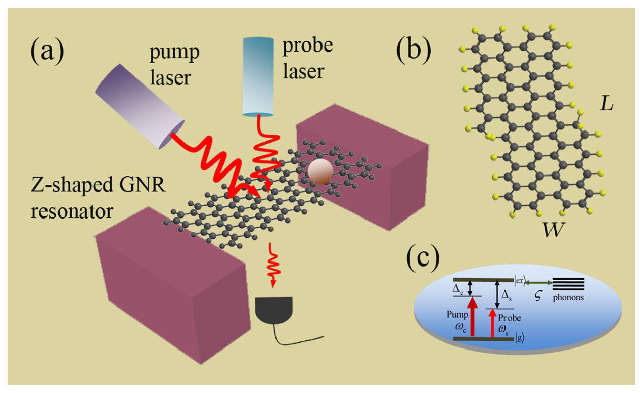
The model consisted of a doubly-clamped Z-shaped GNR resonator, as shown in Figure 1a. Due to the special band structure, graphene's low-energy quasi-particles will behave as Dirac fermions, and the Klein tunneling and chiral effect make it nontrivial to form good quantum dots (localized electron states) in graphene [37]. Several methods have been conceived of to localize electrons (holes) in graphene at present [34,38–41]. GNRs have the form of armchair GNRs [23] and zigzag GNRs [34], which depend on the cutting direction. Scanning tunneling spectroscopy shows that zigzag and armchair edges exhibit different features of the standing wave patterns [42]. In the single-mode regime, zigzag GNRs show perfect conductance for limited scattering to long-range impurities only, which is attributed to the single-valley transport induced by the existence of a chiral mode propagating at the edge of the zigzag GNRs. Moreover, a strain along graphene's zigzag direction might eventually lead to a gap opening at large deformations. Due to these properties, we consider a Z-shaped GNR as a nanomechanical resonator. We propose an alternative approach in which the localized states can exist in the zigzag region of a Z-shaped GNR (see Figure 1b), and its edge bonds are saturated by ordinary hydrogen atoms. As the Z-shaped junction device can completely confine electronic states induced by the topological structure of the junction and by varying the length of the junction, the spatial confinement and the number of discrete levels are modified accordingly [34,41]. A two-level system with the ground state |g〉 and the first excited state (single exciton) |ex〉 characterized by the pseudospin – 1/2 operator Sz (S±) is introduced to describe the exciton in the Z-shaped GNR [33], and the energy level is shown in Figure 1c. Therefore, the Hamiltonian of this localized two-level exciton can be described by He = ħωeSz with the frequency ωe of the exciton.
Clamping and suspending the Z-shaped GNR with SiO2 substrate (see Figure 1a), a doubly-clamped suspended Z-shaped GNR nanomechanical resonator is constructed [33,43]. In the resonator system, we introduce a resonator-bath representation, with the resonator mode (bosonic annihilation and creation operators Φ and Φ+) corresponding to the fundamental in-plane flexural resonance and the bath, including the other GNR vibrational resonances coupled to the 3D substrate that supports the Z-shaped GNR [43]. The lowest-energy resonance corresponds to the fundamental flexural mode, and the resonator is assumed to be characterized by sufficiently high quality factors Q. The eigenmode is described by a quantum harmonic oscillator, and the Hamiltonian is Hr = ħωm(Φ+Φ + 1/2), with the resonator frequency ωm. The excitonic resonance in the GNR resonator plays the same role of the optical cavity that couples to the flexural motion via deformation potential electron-phonon interactions. Then, the interaction between the resonator and exciton is Hr−e = ħωmζSz (Φ+ + Φ), and ζ is the coupling strength [33,43].
Applying a strong pump laser (with frequency ωc) and a weak probe laser (with frequency ωs), termed optical pump-probe technology [35,36], to the GNR resonator system, we obtain the whole Hamiltonian [44] of the coupled system as:
 [D]ρ = 2DρD+ −{D+D, ρ} and
 [D]ρ = DρD+ − ρ are the Lindblad operator describing the incoherent decays. Using the identity 〈Ȯ〉 = Tr(Oρ) for an operator O and a density matrix ρ in the above equation, in the rotating frame at the pump laser frequency ωc, we obtain the following Bloch equations for the coupled GNR resonator system as:
In order to solve these equations, we first take the semiclassical approach by factorizing the GNR resonator and exciton degrees of freedom (〈ΨS−〉 ≈ 〈Ψ〉 〈S−〉), where any entanglement between these systems should be ignored [46]. Here, we make the ansatz [47]:
Inserting these operators into Equations (3)–(5) and neglecting the nonlinear terms, solving the equation set and working to the lowest order in Es, but to all orders in Ec, the linear optical susceptibility can be derived as , where Σ1 = μ2/(ħΓ2) and χ(1)(ωs) is given by:
The imaginary and real parts of χ(1)(ωs) indicate absorption and dispersion, respectively. Actually, the above derivations have been obtained in [33]. In order to investigate the nonlinear optical property of the GNR resonator system, we simultaneously derive the nonlinear optical susceptibility as with , and χ(3)(ωs) is shown as:
The real and imaginary parts of χ(3)(ωs) characterize the Kerr coefficient and nonlinear absorption, respectively.
Based on the nonlinear optical Kerr spectroscopy, a nonlinear optical mass sensing can be implemented. Although the technique of the mass sensor is challenging, the principle of mass sensing is quite simple. Here, the basic principle for mass sensing is mainly measuring the shift of the resonance frequency of the resonator when the external small mass is added on the resonator. Generally, the mass Sm to be weighed is deposited on the surface of GNR resonator with mass M (M ≫ δm), whose resonant frequency ωm will be shifted to ωm + δf. By detecting the frequency shift δf, the mass of deposited particle can be weighed as:
3. Results and Discussions
We consider a Z-shaped GNR of dimensions (L, W) = (14.1,0.7) nm (L and W indicate the length and width of the GNR resonator, respectively) composed of 424 carbon atoms [33,50] with an ambient temperature of 10 K. The model is shown in Figure 1, and the parameters of GNR resonator are shown as follows [33,50]: the fundamental vibration frequency is ωm = 7.477 GHz; the quality factor is Q = 9,000; the decay rate γm = ωm/Q; the effective mass is M = 0.73 × (424mC + 140mH) = 6340 yg (mC = 1.993 yg, mH = 1.674 yg) (1 yg= 10−27 kg); the exciton dephasing rate Γ2 = 1 GHz; and the exciton-resonator coupling strength is about ζ = 0.09 [43]. In Figure 2a, we first show the imaginary part (Imχ(1)) and the real part (Reχ(1)) of linear optical susceptibility as functions of probe-exciton detuning Δs = ωs − ωe at the detuning of the exciton frequency and the pump frequency Δc = 0, which corresponds to the absorption and dispersion of the probe laser, respectively. From the curves, we find that there are two sharp peaks at both sides of the spectra that just correspond to the vibrational frequency of the GNR resonator, and the middle parts indicate the absorption and dispersion of the exciton in the GNR resonator. The physical origin of the phenomenon has been demonstrated in a coupled nanomechanical resonator system [32]. In the case of red sideband Δc = ωm, the imaginary part and real part of linear optical susceptibility exhibit zero absorption and a positive steep slope at Δs = 0, as shown in Figure 2b. Furthermore, at the red sideband, an analogous phenomenon of optomechanically-induced transparency [36] will appear in the system, and we term it as phonon-induced transparency (PIT) [51], as shown in the inset of Figure 2b. This is due to mechanically-induced coherent population oscillation when the pump-probe detuning equals the GNR resonator frequency [32].
Switching the pump-exciton detuning to the blue sideband Δc = −ωm and increasing the pump field intensity, the probe transmission displays a deeper dip, as shown in Figure 3a. In Figure 3a, the negative transmission of the probe laser with the increase of the pump intensity is the so-called electromagnetically-induced absorption (EIA) [52]. However, with further increasing the pump laser intensity, the system switches from EIA to parametric amplification (PA), resulting in the probe laser amplification, as shown in Figure 3b, which has been demonstrated in the conventional optomechanical system [52]. The elliptical inset in Figure 3 shows that there exists a turning point among and , which switches the probe transmission from EIA to PA. Therefore, the GNR resonator system cannot only switch the weak probe laser from off to on, but can also serve as a quantum optomechanical transistor due to the probe amplifier effect. Turning off the pump laser, the weak probe laser displays the transmission spectrum owning to the usual exciton absorption resonance, as shown in Figure 3c. However, turning on the pump laser and fixing the pump-exciton detuning Δc = −ωm, the dip switches to a transmission peak immediately, as shown in Figure 3d. This amplification comes from the quantum interference between the phonons and the beat of the two optical fields via the exciton in the GNR resonator. Due to dressing with the phonon modes, the original two levels of excitons in the GNR resonator system split into several metastable levels. When applying a strong pump laser to the system, the electrons can transit between the metastable levels, which induces the constructive interference and eventually amplifies the weak probe laser.
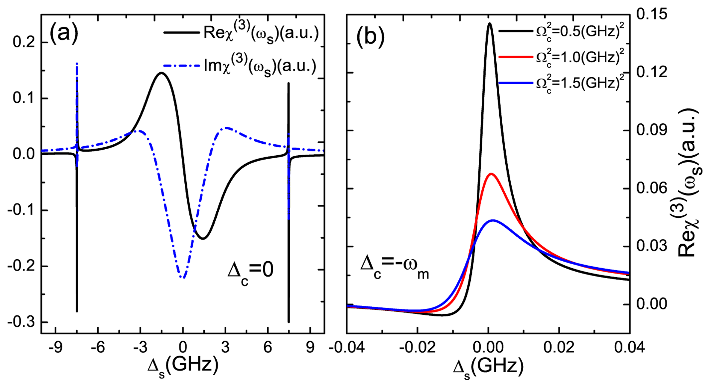
In addition, we also demonstrate the nonlinear optical properties of the GNR resonator system. Figure 4a plots the optical Kerr coefficient Reχ(3) (black curve) and nonlinear absorption Imχ(3) (blue curve) as functions of probe-exciton detuning Δs at Δc = 0. If fixing the pump laser on-resonance with the exciton frequency in the GNR resonator and scanning the probe laser, the large enhanced optical Kerr effect can be obtained at Δs = ±7.477 GHz. The origin of this phenomenon is the quantum interference between the vibration mode of the GNR resonator and the beat of the two optical fields via the exciton when probe-pump detuning δ is adjusted equal to the GNR resonator frequency [32]. Then, we adjust the pump-exciton detuning at Δc = −ωm; the probe laser experiences different optical Kerr coefficients with different pump laser intensities, as shown in Figure 4b. By increasing the intensity of the pump laser, the optical Kerr effect will be weakened significantly. Therefore, the magnitude of the optical Kerr effect can be tuned via controlling the pump intensity, which presents a method for modifying the nonlinear optical features of GNR resonator.
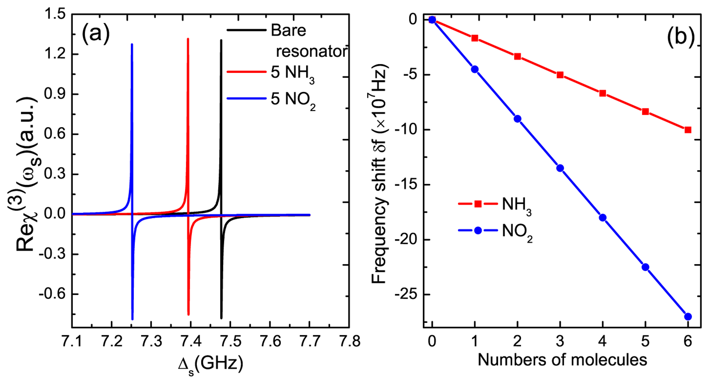
On the other side, to realize the application in mass sensing is the primary goal for the research of GNR resonator systems. In order to implement mass sensing, the first step is to determine the original frequency of the GNR resonator. In Figure 4a, we find that the two sharp peaks induced by the exciton-resonator coupling in the GNR resonator locates accurately at the resonator frequency Δs = ±ωm. This indicates a nonlinear optical scheme for measuring the frequency of the GNR resonator. The physical origin of this result is due to mechanically-induced coherent population oscillation, which makes quantum interference between the resonator and the beat of the two optical fields via the localized exciton when the probe-pump detuning is equal to the resonator frequency. Therefore, if we tune the pump beam properly and scan the probe frequency across the exciton frequency in the spectrum, we can easily obtain the accurate vibration frequency of the GNR resonator. The implementation of the nanomechanical mass sensor depends on monitoring the resonance frequency variation of a nanomechanical resonator when additional mass is adsorbed onto its surface. Once additional mass is deposited on the surface of the resonator, the new frequency of the resonator can be measured, then additional mass can be determined straightly via Equation (10). Here, we propose a nonlinear optical mass sensing via using the Kerr coefficient based on the GNR resonator system. In Figure 5a, we first deposit five NH3 molecules on the GNR resonator and measure the new frequency of the resonator. There is a frequency shift δf1 = 83.5 MHz (see the red curve) compared with the bare resonator without depositing any molecules (see the black curve) onto it. Similarly, five NO2 molecules can also be estimated via the frequency shift δf2 = 225.2 MHz in the probe nonlinear Kerr spectroscopy (see the blue curve). Figure 5b shows the linear relationship between the frequency shifts and the number of deposited molecules. The negative slope gives the mass sensitivity of the resonator. In this way, once the frequency of the resonator is determined, the mass of the resonator can also be obtained accurately via the slope.
To evaluate the sensitivity of the resonator in mass sensing, one significant parameter of mass responsivity ℜ = ωm/(2M) is introduced. Obviously, the lower mass, higher vibration frequency and higher quality factor of the resonator may improve the sensitivity of the sensor effectively. For a practical GNR structure, it will exhibit a wide range of variations in parameters, such as mass, quality factor, exciton-resonator coupling strength, dephasing rate, etc. In the present work, we only consider the parametric values, as shown in the above figures. The change of the size in the GNR resonator will cause the variations in the mass, the resonance frequency and the quality factors. These size-dependent parameters will influence the sensing performance and the sensitivity. The exciton-resonator coupling strength plays a key role in the MoS2 resonator system. If the coupling strength is much larger than ζ = 0.09, there will be a remarkable enhancement of the optical Kerr effect, which will benefit for the performance of the sensor. Further, the dephasing rate of the exciton and the lifetime of the resonator will also affect the performance of the sensor, which have been discussed in detail in the carbon nanotube resonator and a hybrid nanocrystal coupled to a nanomechanical resonator [32]. Experiments carried out in a dilution refrigerator are the drawback of our proposed mass sensing scheme as compared with room temperature mass spectrometry. If the system works as mass sensors at room temperature, the mass sensitivity will be decreased. However, our nonlinear optical mass sensing could be used to monitor nonliving objects, such as N2 molecules and Cr atoms.
In the implementation of mass sensing, both intrinsic and extrinsic noise sources will affect the sensitivity of the sensing devices [53,54]. Thermomechanical noise is one dominant intrinsic noise that will affect the ultimate sensitivity, and implementing the mass sensing in a cryogenic environment can reduce such noise. a mass sensor operated in a linear domain is essential for the use of low-noise optical and electronic detectors when measuring the output signal, and detection noise may be inappreciable in this situation. Furthermore, the mass resolution limits imposed by the intrinsic thermomechanical noise can also be given via the expression , where DR is the dynamic range in units of decibels and BW is the measurement bandwidth, which further reveals that the small effective mass and high quality factor Q of the resonator are crucial for improving the mass sensitivity [48]. However, for many practical applications relying on sophisticated readout equipment, the detection noise as an extrinsic noise source is significant, which will not only obstruct precise sensing, but also will generate the limit of detection of the sensor [53]. Theoretical and experimental investigations have shown that nonlinear behaviors can enhance the sensitivity of the mass sensing [55]. The mass sensor in the nonlinear regime induces large oscillation amplitudes and large output signals without simultaneously amplifying the noise. These benefit counteracting the influence of detection noise and improve the signal-to-noise ratio. Under this condition, compared with the mass sensing in the linear optical region, the use of the nonlinear optical spectrum may overcome the detection noise and offer better performance over the linear optical spectrum where detection noise is the main factor that determines sensitivity [53,54].
We have assumed that the deposited molecules distribute uniformly along the surface of the resonator. Actually, the frequency shift depends on both the deposited mass and its position of adsorption on the surface of the nanomechanical resonator. For the GNR resonator system, the maximum shift is obtained at the center for the fundamental mode of vibration, while the minimal shifts are induced for the adsorption near the edge points. This statistical distribution of frequency shifts has been investigated by building the histogram of event probability versus frequency shift for small ensembles of sequential single molecule or single nanoparticle adsorption events [28].
In our all-optical, nonlinear mass sensor, the particle mass to be measured does not need ionization, and its mass can be directly measured from the nonlinear Kerr spectroscopy conveniently. Our optical mass sensing scheme can also effectively avoid the drawbacks that cause the heating effects based on the electrical measurement, and the nonlinear optical mass sensing may be immune to the detection noises. Besides, the pump-probe scheme generates a beat wave to drive the mechanical resonator, which allows both the high and low frequency of the mechanical resonator. Due to the excellent properties of graphene-based nanoresonator, the nonlinear optical mass sensing proposed here can even reach the detection of single atoms.
4. Conclusion
We have proposed a theoretical model based on a Z-shaped GNR resonator with the optical pump-probe scheme to investigate its coherent optical properties. The phenomenon of phonon-induced transparency, electromagnetically-induced absorption and parametric amplification are demonstrated by the exciton-resonator coupling in the system, which may suggest a quantum optical transistor. By switching the pump-exciton detuning and manipulating the intensity of the pump laser, the optical Kerr effect of the system can be tuned. We further put forward a nonlinear optical mass sensor based on a Z-shaped GNR resonator via the nonlinear optical properties. This nonlinear optical mass sensor may be applied to environmental monitoring and chemical detection and even the measurement of a single atomic mass, due to the excellent properties of the GNR resonator system. Finally, we anticipate that our nonlinear optical detection scheme can be implemented in current experiments.
Acknowledgments
The authors gratefully acknowledge support from the National Natural Science Foundation of China (No.10974133 and No.11274230) and the National Basic Research Program of the Ministry of Science and Technology of China.
Author Contributions
Hua-Jun Chen finished the main work of this paper, including deducing the formulas, plotting the figures and drafting the manuscript. Ka-Di Zhu conceived of the idea, participated in the discussion and provided some useful suggestions. Both authors are involved in the manuscript.
Conflicts of Interest
The authors declare that they have no competing interests.
References
- Chen, C.; Rosenblatt, S.; Bolotin, K.I.; Kalb, W.; Kim, P.; Kymissis, I.; Stormer, H.L.; Heinz, T.F.; Hone, J. Performance of monolayer graphene nanomechanical resonators with electrical readout. Nat. Nanotechnol. 2009, 4, 861–867. [Google Scholar]
- Eichler, A.; Moser, J.; Chaste, J.; Zdrojek, M.; Wilson-Rae, I.; Bachtold, A. Nonlinear damping in mechanical resonators made from carbon nanotubes and graphene. Nat. Nanotechnol. 2011, 6, 339–342. [Google Scholar]
- Song, X.F.; Oksanen, M.; Sillanpaa, M.A.; Craighead, H.G.; Parpia, J.M.; Hakonen, P.J. Stamp transferred suspended graphene mechanical resonators for radio frequency electrical readout. Nano. Lett. 2012, 12, 198–202. [Google Scholar]
- Chen, C.; Lee, S.; Deshpande, V.V.; Lee, G-H.; Lekas, M.; Shepard, K.; Hone, J. Graphene mechanical oscillators with tunable frequency. Nat. Nanotechnol. 2013, 8, 923. [Google Scholar]
- Bunch, J.S.; van der Zande, A.M.; Verbridge, S.S.; Frank, I.W.; Tanenbaum, D.M.; Parpia, J.M.; Craighead, H.G.; McEuen, P.L. Electromechanical resonators from graphene sheets. Science 2007, 315, 490–493. [Google Scholar]
- Moser, J.; Güttinger, J.; Eichler, A.; Esplandiu, M.; Liu, D.; Dykman, M.; Bachtold, A. Ultrasensitive force detection with a nanotube mechanical resonator. Nat. Nanotechnol. 2013, 8, 493–496. [Google Scholar]
- Stapfner, S.; Ost, L.; Hunger, D.; Reichel, J.; Favero, I.; Weig, E.M. Cavity-enhanced optical detection of carbon nanotube Brownian motion. Appi. Phys. Lett. 2013, 102. [Google Scholar] [CrossRef]
- Chiu, H-Y.; Hung, P.; Postma, H.W.C. Atomic-scale mass sensing using carbon nanotube resonators. Nano. Lett. 2008, 8, 4342–4346. [Google Scholar]
- Chaste, J.; Eichler, A.; Moser, J.; Ceballos, G.; Rurali, R.; Bachtold, A. A nanomechanical mass sensor with yoctogram resolution. Nat. Nanotechnol. 2012, 7, 301–304. [Google Scholar]
- Barton, R.A.; Storch, I.R.; Adiga, V.P.; Sakakibara, R.; Cipriany, B,R.; Ilic, B.; Wang, S.P.; Ong, P.; McEuen, P.L.; Parpia, J.M.; Craighead, H.G. Photothermal self-oscillation and laser cooling of graphene optomechanical systems. Nano Lett. 2012, 12, 4681–4686. [Google Scholar]
- Weber, P.; Guttinger, J.; Tsioutsios, I.; Chang, D.E.; Bachtold, A. Coupling Graphene Mechanical Resonators to Superconducting Microwave Cavities. Nano Lett. 2014, 14, 2854–2860. [Google Scholar]
- Song, X.; Oksanen, M.; Li, J.; Hakonen, P.J.; Sillanpää, M.A. Graphene Optomechanics Realized at Microwave Frequencies. Available online: http://arxiv.org/pdf/1403.2965v1.pdf (accessed on 4 September 2014).
- Singh, V.; Bosman, S.J.; Schneider, B.H.; Blanter, Y.M.; Castellanos-Gomez, A.; Steele, G.A. Optomechanical Coupling between a Graphene Mechanical Resonator and a Superconducting Microwave Cavity. Available online: http://arxiv.org/pdf/1403.5165v1.pdf (accessed on 4 September 2014).
- Schwierz, F. Graphene Transistors. Nat. Nanotechnol. 2010, 5, 487–496. [Google Scholar]
- Liao, L.; Bai, J.; Cheng, R.; Lin, Y.; Jiang, S.; Qu, Y.; Huang, Y.; Duan, X.F. Sub-100 nm Channel Length Graphene Transistors. Nano Lett. 2010, 10, 3952–3956. [Google Scholar]
- Das, A.; Pisana, S.; Chakraborty, B.; Piscanec, S.; Saha, S.K.; Waghmare, U.V.; Novoselov, K.S.; Krishnamurthy, H.R.; Geim, A.K.; Ferrari, A.C.; et al. Monitoring dopants by Raman scattering in an electrochemically top-gated graphene transistor. Nat. Nanotechnol. 2008, 3, 210–215. [Google Scholar]
- Liao, L.; Lin, Y.C.; Bao, M.; Cheng, R.; Bai, J.; Liu, Y.; Qu, Y.; Wang, K.L.; Huang, Y.; Duan, X. High-Speed Graphene Transistors with a Self-Aligned Nanowire Gate. Nature 2010, 467, 305–308. [Google Scholar]
- Copuroglu, M.; Aydogan, P.; Polat, E.O.; Kocabas, C.; S üzer, S. Gate-Tunable Photoemission from Graphene Transistors. Nano Lett. 2014, 14, 2837–2842. [Google Scholar]
- Jiao, L.; Zhang, L.; Wang, X.; Diankov, G.; Dai, H. Narrow graphene nanoribbons from carbon nanotubes. Nature 2009, 458, 877–880. [Google Scholar]
- Cai, J.; Ruffieux, P.; Jaafar, R.; Bieri, M.; Braun, T.; Blankenburg, S.; Muoth, A.P.; Seitsonen, M.; Saleh, M.; Feng, X.; et al. Atomically precise bottom-up fabrication of graphene nanoribbons. Nature 2010, 466, 470–473. [Google Scholar]
- Li, X.; Wang, X.; Zhang, L.; Lee, S.; Dai, H. Chemically derived, ultrasmooth graphene nanoribbon semiconductors. Science 2008, 319, 1229–1232. [Google Scholar]
- Jia, X.; Campos-Delgado, J.; Terrones, M.; Meuniere, V.; Dresselhaus, M.S. Graphene edges: A review of their fabrication and characterization. Nanoscale 2011, 3, 86–95. [Google Scholar]
- Wang, X.; Ouyang, Y.; Jiao, L.; Wang, H.; Xie, L.; Wu, J.; Guo, J.; Dai, H. Graphene nanoribbons with smooth edges behave as quantum wires. Nat. Nanotechnol. 2011, 6, 563–567. [Google Scholar]
- Zhang, X.; Yazyev, O.V.; Feng, J.; Xie, L.; Tao, C.; Chen, Y.C.; Jiao, L.; Pedramrazi, Z.; Zettl, A.; Louie, S.G.; et al. Experimentally Engineering the Edge Termination of Graphene Nanoribbons. ACS Nano 2013, 7, 198–202. [Google Scholar]
- Schedin, F.; Geim, A.K.; Morozov, S.V.; Hill, E.W.; Blake, P.; Katsnelson, M.I.; Novoselov, K.S. Detection of Individual Gas Molecules Adsorbed on Graphene. Nat. Mater. 2007, 6, 652–655. [Google Scholar]
- Dan, Y.P.; Lu, Y.; Kybert, N.J.; Luo, Z.; Johnson, A.T.C. Intrinsic Response of Graphene Vapor Sensors. Nano Lett. 2009, 9, 1472–1475. [Google Scholar]
- Li, H.; Yin, Z.; He, Q.; Li, H.; Huang, X.; Lu, G.; Fam, D.W.H.; Tok, A.I.Y.; Zhang, Q.; Zhang, H. Fabrication of Single-and Multilayer MoS2 Film-Based Field-Effect Transistors for Sensing NO at Room Temperature. Small 2012, 8, 63–67. [Google Scholar]
- Naik, A.K.; Hanay, M.S.; Hiebert, W.K.; Feng, X.L.; Roukes, M.L. Towards single-molecule nanomechanical mass spectrometry. Nat. Nanotechnol. 2009, 4, 445–450. [Google Scholar]
- Ekinci, K.L.; Roukes, M.L. Nanoelectromechanical systems. Rev. Sci. Instrum.. 2005, 76. [Google Scholar] [CrossRef]
- Schwab, K.C.; Roukes, M. Putting mechanics into quantum mechanics. Phys. Today 2005, 58, 36–42. [Google Scholar]
- Jiang, C.; Chen, B.; Li, J.J.; Zhu, K.D. Mass spectrometry based on a coupled Cooperpair box and nanomechanical resonator system. Nanoscale. Res. Lett. 2011, 6, 570–578. [Google Scholar]
- Li, J.J.; Zhu, K.D. All-optical mass sensing with coupled mechanical resonator systems. Phys. Rep. 2013, 525, 223–254. [Google Scholar]
- Bin, W.; Zhu, K.D. Nucleonic-resolution optical mass sensor based on a graphene nanoribbon quantum dot. Appl. Opt. 2013, 52, 5816–5821. [Google Scholar]
- Wang, Z.F.; Shi, Q.W.; Li, Q.; Wang, X.; Hou, J.G.; Zheng, H.; Yao, Y.; Chen, J. Z-shaped graphene nanoribbon quantum dot device. Appl. Phys. Lett. 2007, 91. [Google Scholar] [CrossRef]
- Xu, X.; Sun, B.; Berman, P.R.; Steel, D.G.; Bracker, A.S.; Gammon, D.; Sham, L.J. Coherent optical spectroscopy of a strongly driven quantum dot. Science 2007, 317, 929–935. [Google Scholar]
- Weis, S.l.; Rivi'ere, R.; Deleglise, S.; Gavartin, E.; Arcizet, O.; Schliesser, A.; Kippenberg, T.J. Optomechanically induced transparency. Science 2010, 330, 1520–1523. [Google Scholar]
- Castro, A.H.; Guinea, F.; Peres, N.M.R.; Novoselov, K.S.; Geim, A.K. The electronic properties of graphene. Rev. Mod. Phys. 2009, 81. [Google Scholar] [CrossRef]
- Trauzettel, B.; Bulaev, D.V.; Loss, D.; Burkard, G. Spin qubits in graphene quantum dots. Nat. Phys. 2007, 3, 192–196. [Google Scholar]
- Silvestrov, P.G.; Efetov, K.B. Quantum dots in graphene. Phys. Rev. Lett. 2007, 98, 016802. [Google Scholar]
- Pereira, J.M.; Vasilopoulos, P., Jr; Peeters, F.M. Tunable quantum dots in bilayer graphene. Nano Lett. 2007, 7, 946–949. [Google Scholar]
- Guo, G.P.; Lin, Z.R.; Tu, T.; Cao, G.; Li, X.P.; Guo, G.C. Quantum computation with graphene nanoribbon. New J. Phys. 2009, 11, 123005. [Google Scholar]
- Chen, X.; Wan, H.; Song, K.; Tang, D.; Zhou, G. Scanning tunneling microscopy image modeling for zigzagedge graphene nanoribbons. Appl. Phys. Lett. 2011, 98. [Google Scholar] [CrossRef]
- Wilson-Rae, I.; Galland, C.; Zwerger, W.; Imamoğ lu, A. Exciton-assisted optomechanics with suspended carbon nanotubes. New J. Phys. 2012, 14. [Google Scholar] [CrossRef]
- Li, J.J.; He, W.; Zhu, K.D. All-optical Kerr modulator based on a carbon nanotube resonator. Phys. Rev. B. 2011, 83. [Google Scholar] [CrossRef]
- Gardiner, C.W.; Zoller, P. Quantum Noise, 2nd ed.; Springer: Berlin/Heidelberg, Germany, 2000. [Google Scholar]
- Kwon, Y.D.; Armen, M.A.; Mabuchi, H. Femtojoule-Scale All-Optical Latching and Modulation via Cavity Nonlinear Optics. Phys. Rev. Lett. 2013, 111. [Google Scholar] [CrossRef]
- Boyd, R.W. Nonlinear Optics; Academic: San Diego, CA, USA, 1992. [Google Scholar]
- Ekinci, K.L.; Yang, Y.T.; Roukes, M.L. Ultimate limits to inertial mass sensing based upon nanoelectromechanical systems. J. Appl. Phys. 2004, 95. [Google Scholar] [CrossRef]
- Yang, Y.T.; Callegari, C.; Feng, X.L.; Roukes, M.L. Surface Adsorbate Fluctuations and Noise in Nanoelectromechanical Systems. Nano Lett. 2011, 11, 1753–1759. [Google Scholar]
- Kwon, O.K.; Kim, K.; Park, J.; Kang, J.W. Molecular dynamics modeling and simulations of graphenenanoribbon-resonator-based nanobalance as yoctogram resolution detector. Comput. Mater. Sci. 2013, 67, 329–333. [Google Scholar]
- Okamoto, H.; Gourgout, A.; Chang, C.Y.; Onomitsu, K.; Mahboob, I.; Chang, E.Y.; Yamaguchi, H. Coherent phonon manipulation in coupled mechanical resonators. Nat. Phys. 2013, 9, 480–484. [Google Scholar]
- Safavi-Naeini, A.H.; Mayer, A.T.P.; Chan, J.; Eichenfield, M.; Winger, M.; Lin, Q.; Hill, J.T.; Chang, D.E.; Painter, O. Electromagnetically induced transparency and slow light with optomechanics. Nature 2014, 472, 69–73. [Google Scholar]
- Yie, Z.; Zielke, M.A.; Burgner, C.B.; Turner, K.L. Comparison of parametric and linear mass detection in the presence of detection noise. J. Micromech. Microeng. 2011, 21. [Google Scholar] [CrossRef]
- Turner, K.L.; Burgner, C.; Yie, Z.; Shaw, S.W.; Miller, N. Nonlinear dynamics of MEMS systems. AIP. Conf. Proc. 2011, 1339, 111–117. [Google Scholar]
- Dai, M.D.; Eom, K.; Kim, C.W. Nanomechanical mass detection using nonlinear oscillations. Appl. Phys. Lett. 2009, 95. [Google Scholar] [CrossRef]


© 2014 by the authors; licensee MDPI, Basel, Switzerland. This article is an open access article distributed under the terms and conditions of the Creative Commons Attribution license ( http://creativecommons.org/licenses/by/3.0/).
Share and Cite
Chen, H.-J.; Zhu, K.-D. Graphene-Based Nanoresonator with Applications in Optical Transistor and Mass Sensing. Sensors 2014, 14, 16740-16753. https://doi.org/10.3390/s140916740
Chen H-J, Zhu K-D. Graphene-Based Nanoresonator with Applications in Optical Transistor and Mass Sensing. Sensors. 2014; 14(9):16740-16753. https://doi.org/10.3390/s140916740
Chicago/Turabian StyleChen, Hua-Jun, and Ka-Di Zhu. 2014. "Graphene-Based Nanoresonator with Applications in Optical Transistor and Mass Sensing" Sensors 14, no. 9: 16740-16753. https://doi.org/10.3390/s140916740
APA StyleChen, H.-J., & Zhu, K.-D. (2014). Graphene-Based Nanoresonator with Applications in Optical Transistor and Mass Sensing. Sensors, 14(9), 16740-16753. https://doi.org/10.3390/s140916740