A Flexible Ultrasound Transducer Array with Micro-Machined Bulk PZT


Abstract
: This paper proposes a novel flexible piezoelectric micro-machined ultrasound transducer, which is based on PZT and a polyimide substrate. The transducer is made on the polyimide substrate and packaged with medical polydimethylsiloxane. Instead of etching the PZT ceramic, this paper proposes a method of putting diced PZT blocks into holes on the polyimide which are pre-etched. The device works in d31 mode and the electromechanical coupling factor is 22.25%. Its flexibility, good conformal contacting with skin surfaces and proper resonant frequency make the device suitable for heart imaging. The flexible packaging ultrasound transducer also has a good waterproof performance after hundreds of ultrasonic electric tests in water. It is a promising ultrasound transducer and will be an effective supplementary ultrasound imaging method in the practical applications.1. Introduction
Ultrasound transducers are core modules of medical imaging systems. Traditional ultrasound transducers are all based on rigid substrates [1–4], while two-dimension arrays do not conform to the human body shape and line-arrays are difficult to operate. At the same time, transducers cannot be used for implant ultrasound imaging [5,6]. A variety of flexible ultrasound transducers have been reported recently. Mastronardi et al. proposed a flexible ultrasound transducer made of AlN [7], and Zhou et al. mentioned that they took advantage of the properties of ZnO nanowires to make a flexible ultrasound transducer [8]. However, these materials do not have as good performance as lead zirconate titanate (PZT, Pb(Zr1−xTix)O3). Bernstein et al. fabricated monomorph sonar transducers using sol-gel PZT films up to 12 μm in thickness and successfully generated high-resolution images at a range of two meters underwater using 8 × 8 and 6 × 6 arrays [9]. Another piezoelectric micro-fabricated ultrasound transducer (pMUT) structure driven by a sol-gel-deposited PZT layer up to 4 μm thick was built, tested, and simulated by Muralt et al. [10]. However, the piezoelectricity of the sol-gel PZT film is not as good as that of PZT ceramic, so the performance of the transducer has room for improvement. Some researchers have already demonstrated initial imaging results from both one-dimensional (1D) and 2D capacitive micro-fabricated ultrasound transducers (cMUT) [11,12]. Although cMUTs have an almost perfect theoretical coupling factor [13], there are practical operational and fabrication considerations that limit the achievable coupling. The cMUT array has good conformity, impedance matching and high coupling factor, but the high working voltage limits its application in medical fields. The rigid ultrasound transducer also does not fit the body's skin very much and when used in some surgical operations nurses' help is needed to fix the transducer to the patient's chest, so the flexible transducer concept was introduced. Bernstein et al. [14] also fabricated 2D arrays of square and rectangular pMUT membranes driven by PZT. Dausch et al. [15] fabricated pMUT arrays to detect intracardiac echoes. Jiang et al. [16–19] proposed a PMN-PT-based ultrasound array to make the ultrasound transducer flexible, but because the PMN-PT composite is not very flexible there is still room for improvement. Powell and Hayward [20] proposed a method that involves putting a long bar by an array of piezoelectric ceramic glued onto the polymer substrate to make the device flexible, but the deficiency is that their devices are not reliable. P.I. Hsu et al. proposed another structure that made the ultrasound transducer flexible [21]. Anthony Gachagan et al. mentioned that the piezoelectric ceramic can be divided firstly and then the pitch of the ceramics refilled [22], but it is difficult to meet the requirements for the precise distance between the cells. Khuri-Yakub et al. proposed a flexible capacitive micro-machined transducer array (cMUT) by embedding bulk PZT in a polymer matrix [23]. Grandfest et al. studied flexible pMUT and made progressive improvements. They etched silicon substrates into blocks with trenches, and the trenches were refilled with polydimethylsiloxane (PDMS). However, the PDMS filled in the pitch was not robust and the device needs more steeps to make it work. Flexible piezoelectric micro-fabricated ultrasound transducers (pMUT) were reported by Singh et al. [24,25]. They used a similar strategy as the flexible cMUT, but mounted diced PZT ceramics onto the silicon blocks. The trenches were partly refilled with polyimide (PI), which made for flexible joints, but their flexible joints were not robust enough and could not endure more substantial bending.
2. Design and Simulation
A micro-machined flexible ultrasound transducer array is reported in this paper. Prior work has been done a foreshadowing for the ultrasound transducer [26,27]. The transducer array is based on MEMS technology, so it has good uniformity and can be scaled down. The piezoelectric elements which are shown in Figure 1 are wrapped by polyimide and biomedical-grade PDMS, which is flexible, and robust. There are two reasons why we chose ∼2 MHz. Firstly, the ultrasound transducer can emitting ultrasound waves to the heart to make an image, so we can know the internal structure to identify some diseases. Secondly, ultrasound imaging is real-time imaging, so we can observe the motion of the heart, and we can detect some diseases from the abnormal movement. The traditional hard substrate ultrasound transducer for heart imaging is also about 2–3 MHz, so our flexible ultrasound transducer is also ∼2 MHz. The resonant frequency is decided by many parameters. The main parameters are the size of the PZT, the thickness of the PZT, the thickness of polyimide and PDMS and so on. The experiments show as good performance of the ultrasound transducer as that of the traditional ones. The transducer is well characterized, and has potential applications in medical imaging, especially in real-time surgery.
The materials are selected for the following reasons: polyimide (PI) was chosen for its good biocompatibility and flexibility. However, the Young modulus of PI is not close to that of the human body. The Young modulus and the acoustic impedance of the PDMS are close to that of the body, but it is not a good choice for the substrate of the device. This is because the surface of PDMS is not as smooth as PI and the coefficient of thermal expansion difference between the PDMS and electrode material is very large, so the substrate will be crushed when sputtering Au. Considering the above factors, PI was the most suitable material for the substrate.
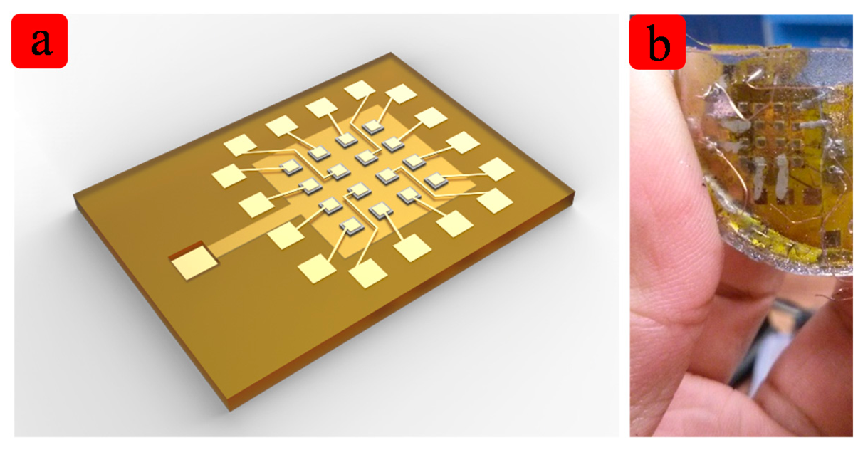
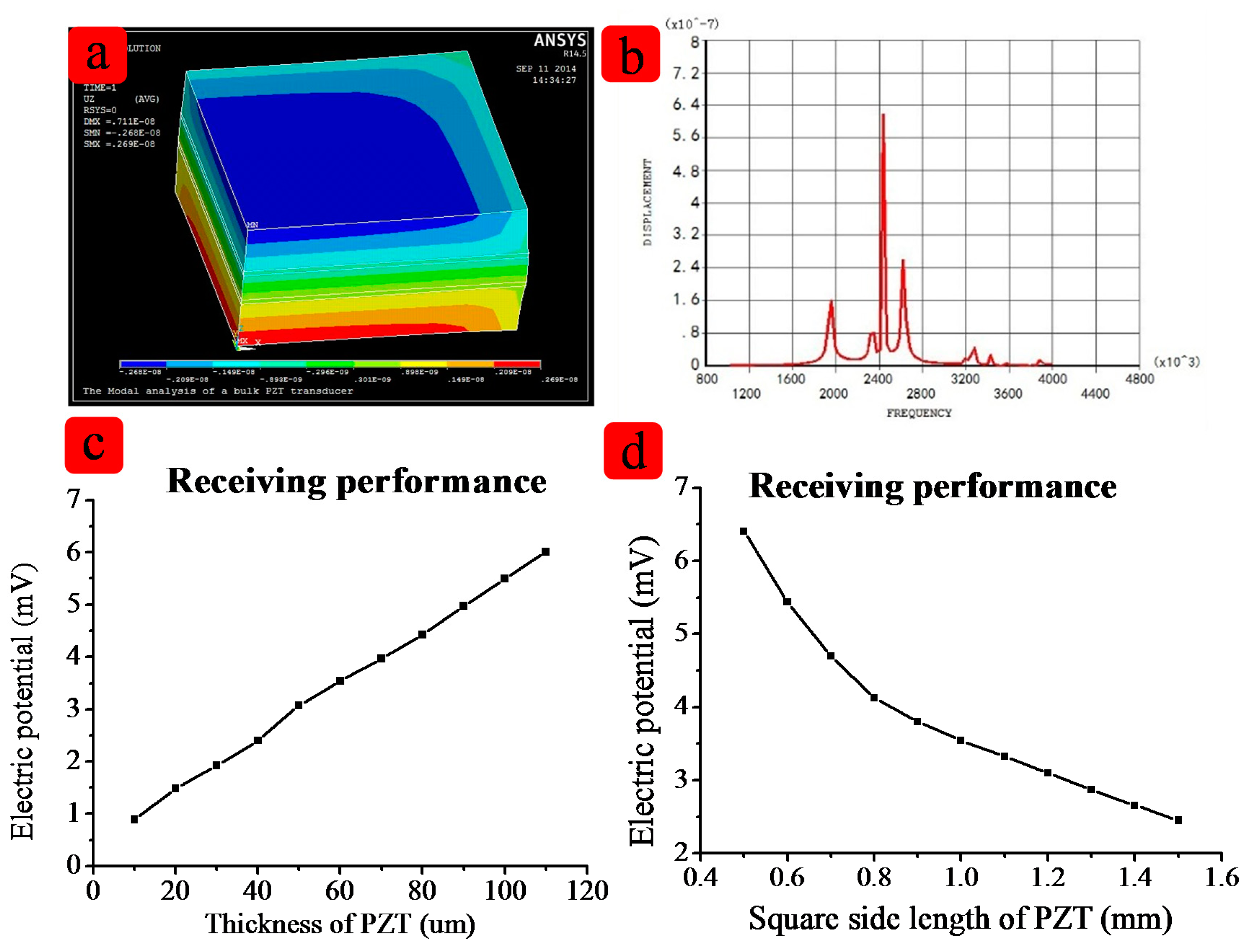
The structure of this device was designed by the simulation tools. Table 1 lists several key features of the flexible ultrasound array. To validate the design, both Finite Element Analysis (Ansys) and direction analysis (Matlab) were carried out. Because all 16 elements are the same, so one cell was selected in the simulation, as shown in Figure 2a.
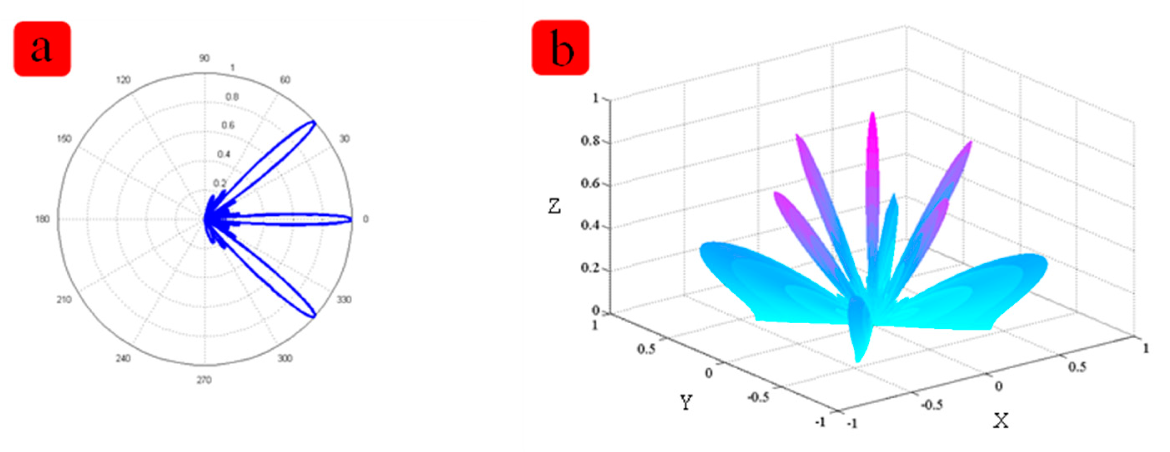
The length and width are 1 mm × 1 mm. Figure 2c shows the relationship between the thickness and the receiving performance. Figure 2d shows relationship between size and the receiving performance. In order to achieve the better performance of the device, the distance between two elements is a very important feature. Matlab modeling was applied. Figure 3 shows the simulation result about the distance between two elements. When the distance between two cells increases, the main lobe beam is becoming narrower, and the directional accuracy is becoming high, however, the side lobe will become bigger too. According to the simulation result, the effect of PDMS are very limited on the resonant frequency, but the thickness of the PDMS affects the vibration displacement, so the PDMS should not too thick. After simulation and experimenta, we chose 100 μm PDMS for our device. After the simulation, we chose 1 mm for the distance between two cells. All the parameters including the specific software module, material properties used are listed in Tables 2 and 3.
3. Device Fabrication
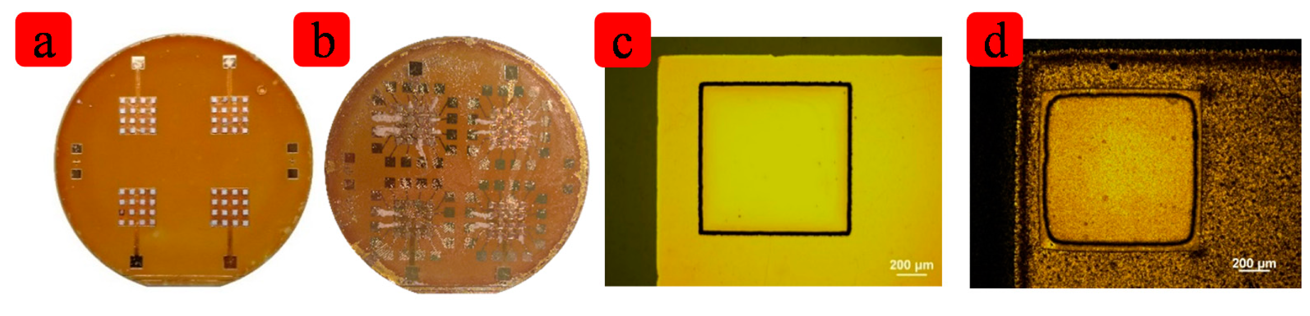
Firstly, the polyimide thin films was spin-coated on a silicon wafer. The thickness is about 10 μm. The contact between PI film and wafer is very firm so the PI film can persist on the silicon substrate for a long time. The second step is the lithography, and then Ti/Au (200 Å/1000 Å) film was sputtered and patterned by lift-off. The third step is spin-coating of another thick PI layer and etching the holes where the PZT elements will be placed. This PI layer is about 80 μm thick. In order to pattern the PI film, another lithography process is applied and the photoresist works as a mask. Then the DRIE etching is carried out. The PI film before and after etching can be seen in the Figure 4a,b. The edge is not straight because the etching is anisotropic. In the corner, the space is limited so the chemical reactants cannot easily removed from the surface of the PI film, so the corners are not sharp any more. After 100 minutes' etching, the bottom electrode is revealed and this can be confirmed by detecting the resistance between two pads of bottom electrode. The fourth step is putting the diced PZT in the holes via silver paste. It can be seen in Figure 4c. The fifth step is to form the top electrode. The Ti/Au (200 Å/1000 Å) film was sputtered and patterned by lift-off process to form the top electrode and the pads. It can be seen in Figure 4d. The sixth step is wire-bonding. The copper wire was welded to the pad for device testing. Then the whole device is removed from the Si substrate by heating on a hotplate, with a little water on it. The PI film is hydrophobic, so it very easy to peel off from the silicon. The last step is coating the device with biomedical-grade PDMS from the top side to the bottom. This PDMS film is about 1 mm thick and is robust enough to make sure the copper wire would not break off from the device. Figure 4 lists parts process of the devices.
4. Device Characterization and Discussion
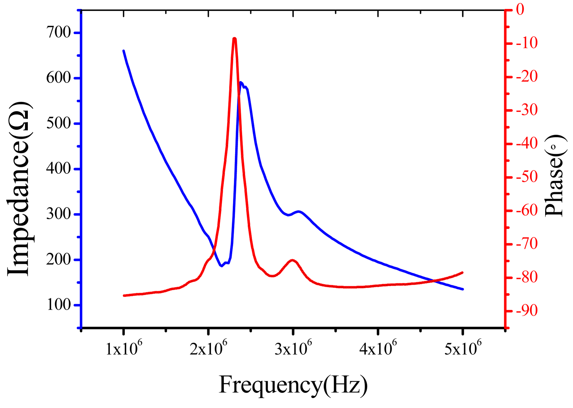
The device must be polarized before the test in the polydimethylsiloxane fluid at about 120 °C and 400 V DC voltage was applied for 40 min for polarization. An Agilent HP4294A precision impedance analyzer was used to measure the electrical impedance. The device was biased at a constant DC voltage and a variable AC voltage. The impedance is shown in Figure 5. The center frequency was about 2.2 MHz. The electromechanical coupling coefficient was calculated by following formula:
The calculated electromechanical coupling coefficient factor from Figure 5 is about 0.21, which is lower than that of the bulk PZT material. This is because the device is wrapped with flexible materials like PI and PDMS so the damping effect cannot be ignored. Actually because this device is working in d31 mode, the electromechanical coupling coefficient is very considerable.
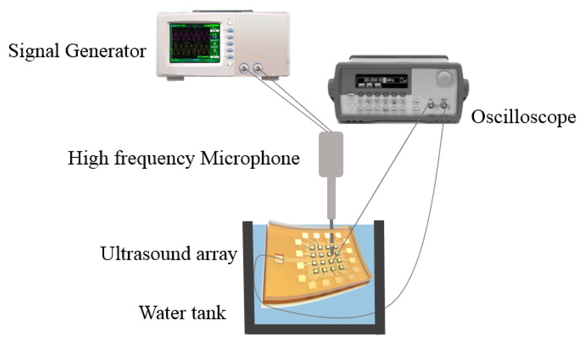
The device is flexible and waterproof so the tests can be carried out in the water. The resonant frequency in water was also extracted from the measurements made using the high frequency microphone. Figure 5 shows the dependence of the open circuit resonant frequency on the DC bias voltage. The measurement results agree with the model within 5% of error. The difference can be explained by processing uncertainties, such as the gap between two cells and the PI layer and PDMS layer thickness. Another possible cause for the discrepancies is the effect of the silver paste, which is not considered in the model. The full effect of the PDMS coating on the device performance are currently under investigation both by finite element simulation and experiments. The schematic of FpMUT for ultrasonic measurement is shown in Figure 6.
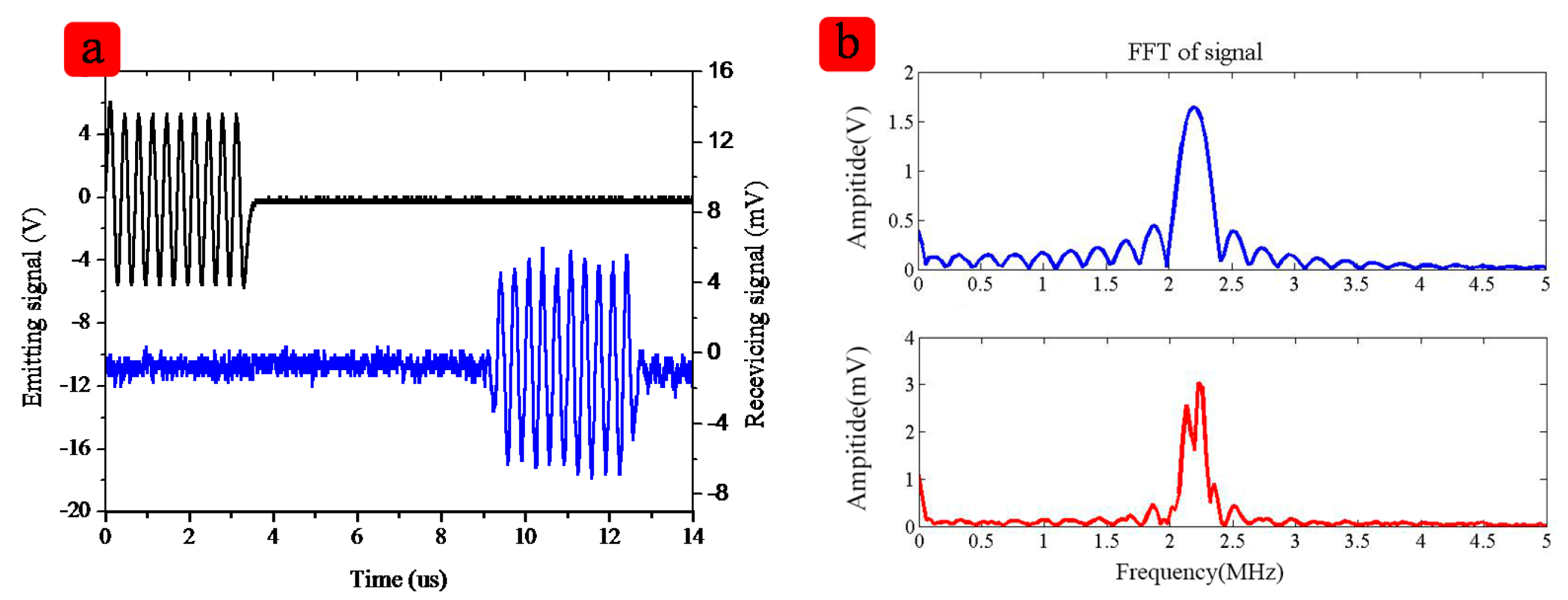
The measurement system includes a signal generator, an oscilloscope and a high frequency microphone. The signal generator emits a series of signal to the flexible device and after several microseconds the high frequency microphone will receive the signal from the device. It can be seen in Figure 7b, that the Fast Fourier Transform (FFT) of the signal shows the signal received by device is the signal sent before, proving the response is caused by the emitting signal. All 16 elements show good uniformity. The emission and receiving performance for the array is summarized in Table 4.
In the water the ultrasonic velocity is about 1500 m/s, and the frequency of the device is about 2.2 MHz, the wavelength is about 0.7 mm, therefore the distance between two elements is about 1.5–2 times the wavelength, so from the result, it can be also calculated that the distance between two elements is about 1.4 cm, which is as same as the measurement. The spectrum signal of the signal has a concave shape, which shows that there are some signals missing. That is because there are some reflections between the junction of the PI film and the PDMS. However, the most valid signals can support the needs of medical imaging applications.
5. Conclusions
In this paper we propose a novel flexible 2-dimensional ultrasound array using bulk PZT with a resonant frequency over 2 MHz. The arrays consist of 16 elements and each element was of 1 mm × 1 mm size and with a pitch of 1 mm. The thickness is about 100 μm. The bandwidth is about 21%. The electromechanical coupling coefficient is about 22.25%. Electric impedance and pulse-echo experiments were applied. All 16 elements showed good uniformity and were robust enough to test in the water. The good flexibility and high electromechanical coupling coefficient show the high potential of the proposed device in medical applications.
Acknowledgments
This work was supported by the National Natural Science Foundation of China (61025021, 61434001) and 973 Program (2015CB352100), Tsinghua National Laboratory for Information Science and Technology Cross-discipline Foundation, the National Key Project of Science and Technology (2011ZX02403-002) and the Special Fund for Agro-scientific Research in the Public Interest (201303107).
Author Contributions
Zhe Wang and Qing-Tang Xue conceived and designed the experiments, performed the experiments; Zhe Wang analyzed the data; Yuan-Quan Chen contributed the analysis simulation; Yi Shu, He Tian, Yi Yang, Dan Xie and Jian-Wen Luo co-wrote the manuscript. Tian-Ling Ren was responsible for the redaction of the paper.
Conflicts of Interest
The authors declare no conflict of interest.
References
- Akasheh, F.; Myers, T.; Fraser, J.D.; Bose, S.; Bandyopadhyay, A. Development of piezoelectric micromachined ultrasonic transducers. Sens. Actuators A Phys. 2004, 111, 275–287. [Google Scholar]
- Wang, Z.; Zhu, W.; Miao, J.; Zhu, H.; Chao, C.; Tan, O.K. Micromachined thick film piezoelectric ultrasonic transducer array. Sens. Actuators A Phys. 2006, 130, 485–490. [Google Scholar]
- Akasheh, F.; Fraser, J.D.; Bose, S.; Bandyopadhyay, A. Piezoelectric micromachined ultrasonic transducers: Modeling the influence of structural parameters on device performance. IEEE Trans. Ultrason. Ferroelectr. Freq. Control 2005, 52, 455–468. [Google Scholar]
- Lukacs, M.; Sayer, M.; Foster, S. Single element high frequency (<50 MHz) PZT sol gel composite ultrasound transducers. IEEE Trans. Ultrason. Ferroelectr. Freq. Control 2000, 47, 148–159. [Google Scholar]
- Holmes, D.R., III; Davis, B.J.; Bruce, C.J.; Robb, R.A. 3D visualization, analysis, and treatment of the prostate using trans-urethral ultrasound. Comput. Med. Imaging Graph. 2003, 27, 339–349. [Google Scholar]
- Culjat, M.O.; Dann, A.E.; Lee, M.; Bennett, D.B.; Schulam, P.G.; Lee, H.; Grundfes, W.S.; Singh, R.S. Transurethral ultrasound catheter-based transducer with flexible polyimide joints. Proceedings of the 2009 IEEE International Ultrasonics Symposium (IUS), Rome, Italy, 20–23 September 2009; pp. 2209–2212.
- Mastronardi, V.M.; Guido, F.; Amato, M.; de Vittorio, M.; Petroni, S. Piezoelectric ultrasonic transducer based on flexible AlN. Microelectron. Eng. 2014, 121, 59–63. [Google Scholar]
- Zhou, X.; Zhao, C.; Hou, R.; Zhang, J.; Kirk, K.; Hutson, D.; Guo, Y.J.; Hu, P.A.; Peng, S.M.; Zu, X.T.; et al. Sputtered ZnO film on aluminium foils for flexible ultrasonic transducers. Ultrasonics 2014. [Google Scholar] [CrossRef]
- Bernstein, J.; Houston, K.; Niles, L.; Li, K.; Chen, H.; Cross, L.; Li, K.; Udayakumar, K. Integrated ferroelectric monomorph transducers for acoustic imaging. Integrat. Ferroelectr. 1997, 15, 289–307. [Google Scholar]
- Muralt, P.; Schmitt, D.; Ledermann, N.; Baborowski, J.; Weber, P.; Steichen, W.; Petitgrand, S.; Bosseboeuf, A.; Setter, N.; Gaucher, P. Study of PZT coated membrane structures for micromachined ultrasonic transducers [medical imaging]. Proceedings of the 2001 IEEE Ultrasonics Symposium, Atlanta, GA, USA, 7–10 October 2001; pp. 907–911.
- Oralkan, O.; Ergun, A.S.; Cheng, C.-H.; Johnson, J.A.; Karaman, M.; Lee, T.H.; Khuri-Yakub, B.T. Volumetric ultrasound imaging using 2-D CMUT arrays. IEEE Trans. Ultrason. Ferroelectr. Freq. Control. 2003, 50, 1581–1594. [Google Scholar]
- Schindel, D.; Hutchins, D.; Grandia, W. Capacitive and piezoelectric air-coupled transducers for resonant ultrasonic inspection. Ultrasonics 1996, 34, 621–627. [Google Scholar]
- Reynolds, P.; Fraser, J. Finite element determination of effective electromechanical coupling coefficient with applications to piezoelectric and electrostatic transducers. Proceedigns of the Ultrasonics International conference, Delft, The Netherlands, 2–5 July 2001.
- Bernstein, J.J.; Finberg, S.L.; Houston, K.; Niles, L.C.; Chen, H.D.; Eric Cross, L.; Li, K.K.; Udayakumar, K. Micromachined high frequency ferroelectric sonar transducers. IEEE Trans. Ultrason. Ferroelectr. Freq. Control 1997, 44, 960–969. [Google Scholar]
- Dausch, D.E.; Gilchrist, K.H.; Carlson, J.B.; Hall, S.D.; Castellucci, J.B.; von Ramm, O.T. In Vivo Real-Time 3-D Intracardiac Echo Using PMUT Arrays. IEEE Trans. Ultrason. Ferroelectr. Freq. Control 2014, 61, 1754–1764. [Google Scholar]
- Jiang, X.; Snook, K.; Cheng, A.; Hackenberger, W.; Geng, X. Micromachined PMN-PT single crystal composite transducers— 15 – 75 MHz PC-MUT. Proceedings of the Ultrasonics Symposium, Beijing, China, 2–5 November 2008; pp. 164–167.
- Jiang, X.; Snook, K.; Liu, R.; Geng, X.; Hackenberger, W.S. Fabrication and characterization of high frequency phased arrays for NDE imaging. Proceedigns of the Nondestructive Characterization for Composite Materials, Aerospace Engineering, Civil Infrastructure, and Homeland Security, San Diego, CA, USA, 8 April 2010.
- Yuan, J.; Rhee, S.; Jiang, X. 60 MHz PMN-PT based 1-3 composite transducer for IVUS imaging. Proceedings of the Ultrasonics Symposium, Beijing, China, 2–5 November 2008; pp. 682–685.
- Yuan, J.R.; Jiang, X.; Cao, P.-J.; Sadaka, A.; Bautista, R.; Snook, K.; Rehrig, P.W. 5C-5 High Frequency Piezo Composites Microfabricated Ultrasound Transducers for Intravascular Imaging. Proceedings of the Ultrasonics Symposium, Vancouver, BC, Canada, 2–6 October 2006; pp. 264–268.
- Powell, D.J.; Hayward, G. Flexible ultrasonic transducer arrays for nondestructive evaluation applications. I. The theoretical modeling approach. IEEE Trans. Ultrason. Ferroelectr. Freq. Control 1996, 43, 385–392. [Google Scholar]
- Hsu, P.; Huang, M.; Xi, Z.; Wagner, S.; Suo, Z.; Sturm, J. Spherical deformation of compliant substrates with semiconductor device islands. J. Appl. Phys. 2004, 95, 705–712. [Google Scholar]
- Gachagan, A.; Hayward, G.; Banks, R. A flexible piezoelectric transducer design for efficient generation and reception of ultrasonic lamb waves. IEEE Trans. Ultrason. Ferroelectr. Freq. Control. 2005, 52, 1175–1182. [Google Scholar]
- Zhuang, X.; Lin, D.-S.; Oralkan, Ö.; Khuri-Yakub, B.T. Fabrication of flexible transducer arrays with through-wafer electrical interconnects based on trench refilling with PDMS. J. Microelectromech. Syst. 2008, 17, 446–452. [Google Scholar]
- Singh, R.S.; Culjat, M.O.; Lee, M.; Bennett, D.B.; Natarjan, S.; Cox, B.P.; Brown, E.R.; Grundfest, W.S.; Lee, H. Conformal Ultrasound Imaging System. Acoust. Imaging 2011, 30, 211–222. [Google Scholar]
- Singh, R.S.; Natarajan, S.; Lee, M.; Dann, A.; Cox, B.P.; Bennett, D.B.; Brown, E.R.; Lee, H.; Grundfest, W.S.; Culjat, M.O. Development of an ultrasound imaging system for needle guidance. Proceedings of the 2009 IEEE International Ultrasonics Symposium (IUS), Rome, Italy, 20–23 September 2009; pp. 1852–1855.
- Zhan, J.; Ren, T.; Yang, C.; Yang, Y.; Liu, L.; Wang, A. Design of magnetic RF inductor in CMOS. Tsinghua Sci. Technol. 2012, 17, 78–83. [Google Scholar]
- Zhang, Y.; Zhang, Z.; Pang, B.; Yuan, L.; Ren, T. Tiny MEMS-based pressure sensors in the measurement of Intracranial Pressure. Tsinghua Sci. Technol. 2014, 19, 161–167. [Google Scholar]


| Center frequency | 2 MHz |
| Element-to-element pitch | 1 mm |
| Number of elements | 16 |
| Size of element | 1 mm × 1 mm |
| Structure Layer | Model Type |
|---|---|
| PZT | SOLID5 |
| Polyimide | SOLID45 |
| PDMS | SOLID45 |
| Electrode (Au) | SHELL41 |
| Stiffness Constant | c11 | c12 | c13 | c33 | c44 |
|---|---|---|---|---|---|
| (Gpa) | 135 | 67.4 | 68.1 | 113 | 22.2 |
| Piezoelectric strain constant | e31 | e33 | e15 | ||
| (C/m2) | −1.86 | 9 | 9.8 |
| Number of elements | 16 |
| Average center frequency | 2.27 MHz |
| High/Low center frequency | 2.4 MHz/2.14 MHz |
© 2015 by the authors; licensee MDPI, Basel, Switzerland. This article is an open access article distributed under the terms and conditions of the Creative Commons Attribution license ( http://creativecommons.org/licenses/by/4.0/).
Share and Cite
Wang, Z.; Xue, Q.-T.; Chen, Y.-Q.; Shu, Y.; Tian, H.; Yang, Y.; Xie, D.; Luo, J.-W.; Ren, T.-L. A Flexible Ultrasound Transducer Array with Micro-Machined Bulk PZT. Sensors 2015, 15, 2538-2547. https://doi.org/10.3390/s150202538
Wang Z, Xue Q-T, Chen Y-Q, Shu Y, Tian H, Yang Y, Xie D, Luo J-W, Ren T-L. A Flexible Ultrasound Transducer Array with Micro-Machined Bulk PZT. Sensors. 2015; 15(2):2538-2547. https://doi.org/10.3390/s150202538
Chicago/Turabian StyleWang, Zhe, Qing-Tang Xue, Yuan-Quan Chen, Yi Shu, He Tian, Yi Yang, Dan Xie, Jian-Wen Luo, and Tian-Ling Ren. 2015. "A Flexible Ultrasound Transducer Array with Micro-Machined Bulk PZT" Sensors 15, no. 2: 2538-2547. https://doi.org/10.3390/s150202538