
Broadband and High Sensitive Time-of-Flight Diffraction Ultrasonic Transducers Based on PMNT/Epoxy 1–3 Piezoelectric Composite


Abstract
:1. Introduction
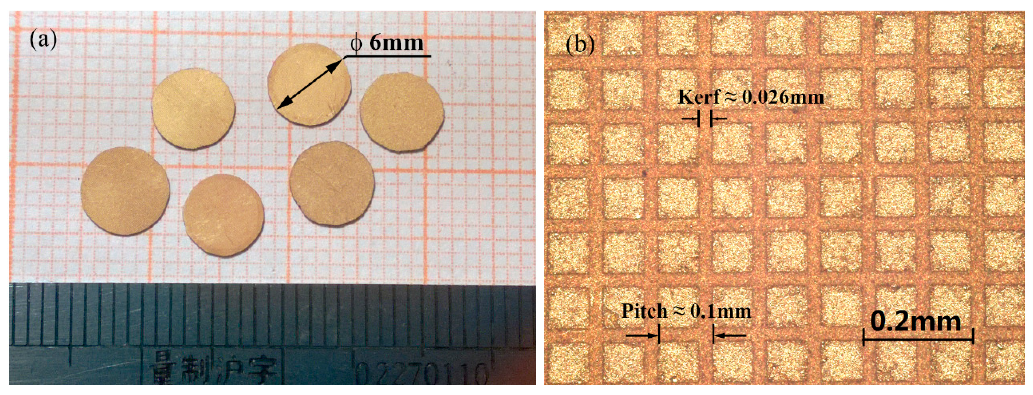
2. Composite Preparation


| ρ (kg/m3) | @ 1 kHz | d33 (pC/N) | kt | Qm | Dielectric Loss @ 1 kHz (tan δ) | Nt (Hz·m) | Z ( kg/(m2·s)) | |
|---|---|---|---|---|---|---|---|---|
| PMNT | 8100 | 5500 | 2000 | 0.62 | 100 | 0.005 | 2300 | 37 |
| PMNT/epoxy 1–3 composite | 4955 | 2134 | 1208 | 0.857 | 15 | 0.012 | 1830 | 18.2 |
| PZT-5H | 7500 | 3100 | 600 | 0.51 | 65 | 0.018 | 1950 | 34 |
| PZT/epoxy 1–3 composite | 4190 | 3400 | 593 | 0.59 | 20 | 0.024 | 1600 | 13.4 |
3. TOFD Transducer Design and Fabrication
3.1. Design and Simulation
| Material | Use | Weight Ratio (Epoxy:Powder) | Long Sound Velocity (m/s) | Density (kg/m3) | Acoustic Impedance ( kg/(m2·s)) | |
|---|---|---|---|---|---|---|
| Epo-Tek 301/Zirconia | Matching layer | Scheme I | 1:1.2 | 2435 | 1970 | 4.79 |
| Scheme II | 1:1.6 | 2495 | 2272 | 5.67 | ||
| Epo-Tek 301/Tungsten | Backing layer | 1:5.5 | 1589 | 5320 | 8.45 | |

| fc (MHz) | BW @ −6 dB (%) | Pulse Length @ −20 dB (μs) | Pk Ampl (dB, re 1 V/V) | |
|---|---|---|---|---|
| Scheme I | 7.07 | 124.7% | 0.21 | −49.97 |
| Scheme II | 6.34 | 104.8% | 0.24 | −49.56 |
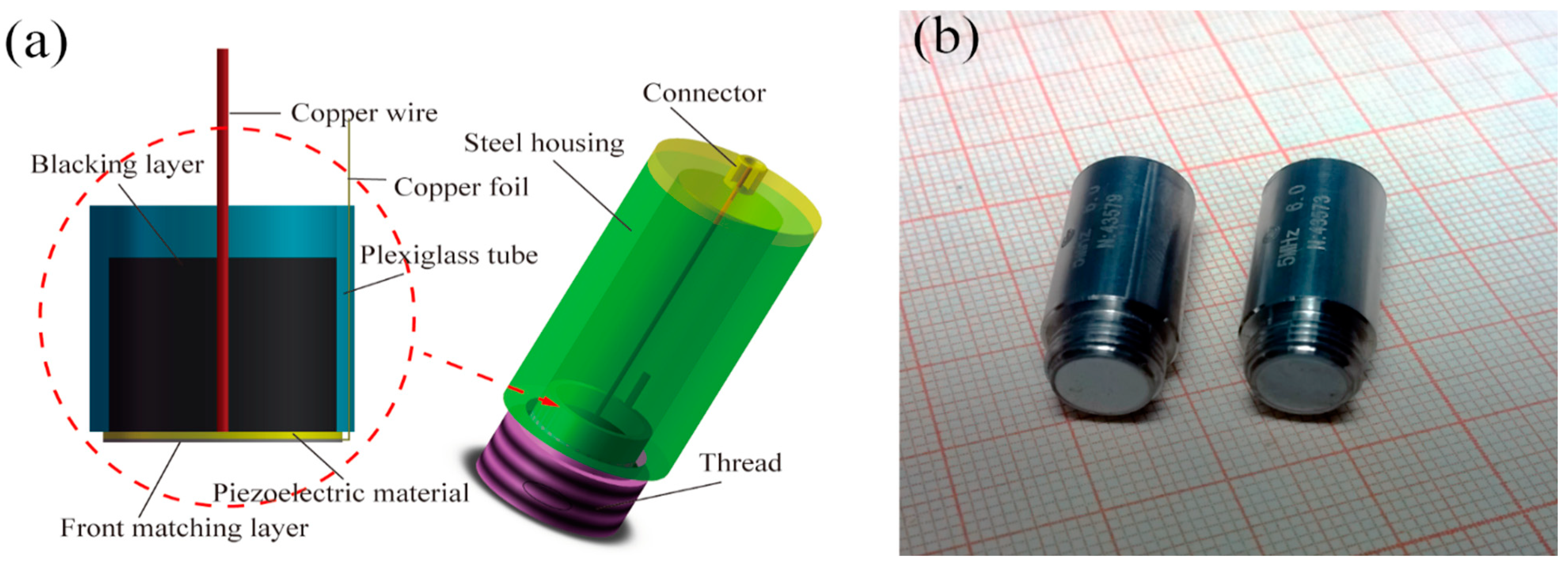
3.2. Fabrication

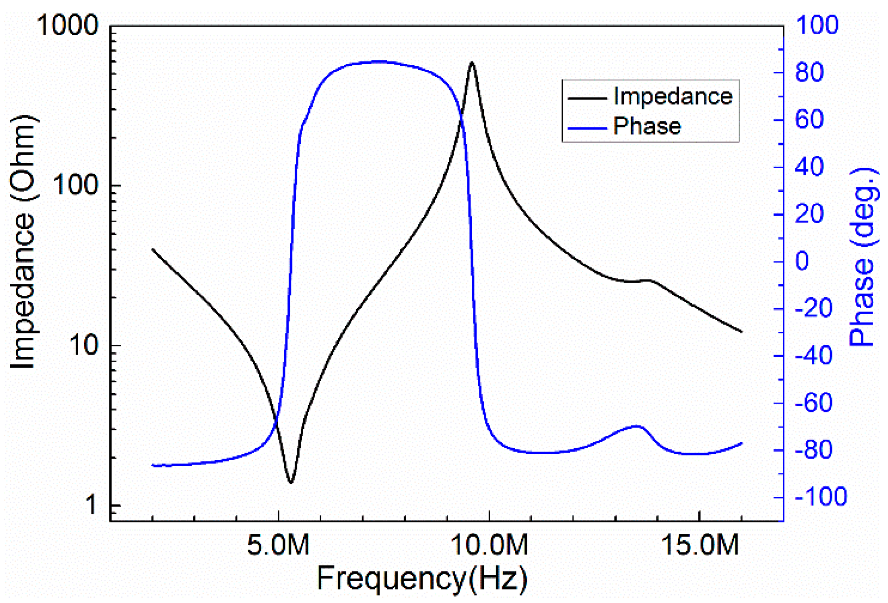
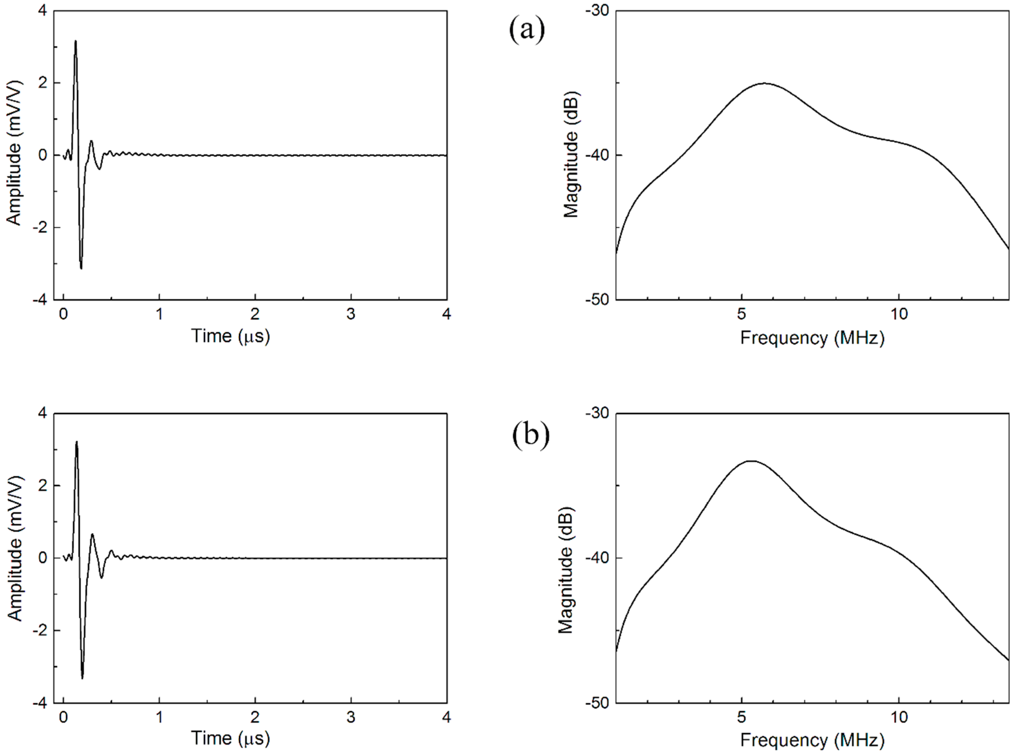
3.3. Transducer Performances
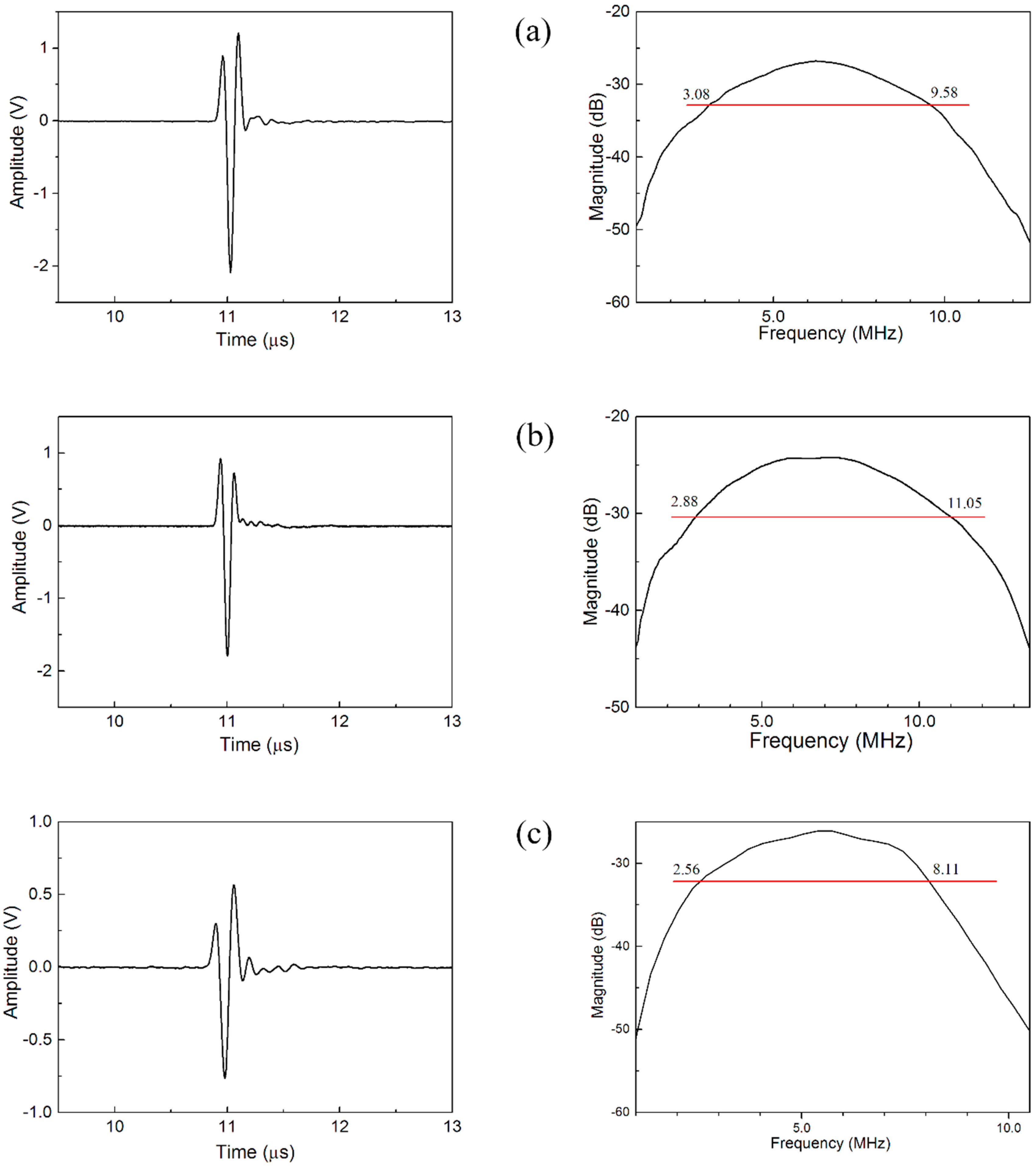
| fc (MHz) | BW @ −6 dB (%) | Pulse Length @ −20 dB (μs) | Relative Pulse-Echo Sensitivity (dB) | Electrical Impedance @ fc (Ω) | |
|---|---|---|---|---|---|
| Scheme I | 6.97 | 117.3 | 0.21 | −24.08 | 38.7 |
| Scheme II | 6.33 | 102.7 | 0.23 | −21.93 | 46.2 |
| PZT/epoxy 1–3 composite | 5.34 | 103.9 | 0.27 | −27.96 | 56.2 |
4. Conclusions
Acknowledgments
Author Contributions
Conflicts of Interest
References
- Kim, K.B.; Hsu, D.K.; Ahn, B.; Kim, Y.G.; Barnard, D.J. Fabrication and comparison of PMN-PT single crystal, PZT and PZT-based 1–3 composite ultrasonic transducers for NDE applications. Ultrasonics 2010, 50, 790–797. [Google Scholar] [CrossRef] [PubMed]
- Robertson, D.; Hayward, G.; Gachagan, A.; Murray, V. Comparison of the performance of PMN-PT single-crystal and ceramic composite arrays for NDE applications. Insight 2006, 48, 97–100. [Google Scholar] [CrossRef]
- Peng, J.; Luo, H.S.; He, T.H.; Xu, H.Q.; Lin, D. Elastic, dielectric, and piezoelectric characterization of 0.70Pb(Mg1/3Nb2/3)O3-0.30PbTiO3 single crystals. Mater. Lett. 2005, 59, 640–643. [Google Scholar] [CrossRef]
- Bokov, A.A.; Ye, Z.G. Ferroelectric properties of monoclinic Pb(Mg1/3Nb2/3)O3-PbTiO3 crystals. Phys. Rev. B 2002, 66, 094112:1–094112:5. [Google Scholar]
- Luo, H.S.; Xu, G.S.; Xu, H.Q.; Wang, P.C.; Yin, Z.W. Compositional homogeneity and electrical properties of lead magnesium niobate titanate single crystals grown by a modified bridgman technique. Jpn. J. Appl. Phys. Part 1-Reg. Pap. Short Notes Rev. Pap. 2000, 39, 5581–5585. [Google Scholar] [CrossRef]
- Park, S.E.; Shrout, T.R. Characteristics of relaxor-based piezoelectric single crystals for ultrasonic transducers. IEEE Trans. Ultrason. Ferroelectr. Freq. Control 1997, 44, 1140–1147. [Google Scholar] [CrossRef]
- Zhou, D.; Cheung, K.F.; Lam, K.H.; Chen, Y.; Chiu, Y.C.; Dai, J.; Chan, H.L.W.; Luo, H. Broad-band and high-temperature ultrasonic transducer fabricated using a Pb(In1/2Nb1/2)O3-Pb(Mg1/3Nb2/3)O3-PbTiO3 single crystal/epoxy 1–3 composite. Rev. Sci. Instrum. 2011, 82, 055110:1–055110:7. [Google Scholar] [CrossRef]
- Chen, Y.; Lam, K.-H.; Zhou, D.; Yue, Q.; Yu, Y.; Wu, J.; Qiu, W.; Sun, L.; Zhang, C.; Luo, H.; et al. High performance relaxor-based ferroelectric single crystals for ultrasonic transducer applications. Sensors 2014, 14, 13730–13758. [Google Scholar] [CrossRef] [PubMed]
- Wang, W.; Or, S.W.; Yue, Q.; Zhang, Y.; Jiao, J.; Ren, B.; Lin, D.; Leung, C.M.; Zhao, X.; Luo, H. Cylindrically shaped ultrasonic linear array fabricated using pimnt/epoxy 1–3 piezoelectric composite. Sens. Actuators A Phys. 2013, 192, 69–75. [Google Scholar] [CrossRef]
- Wang, W.; Or, S.W.; Yue, Q.; Zhang, Y.; Jiao, J.; Leung, C.M.; Zhao, X.; Luo, H. Ternary piezoelectric single-crystal pimnt based 2-2 composite for ultrasonic transducer applications. Sens. Actuators A Phys. 2013, 196, 70–77. [Google Scholar] [CrossRef]
- Zhang, Y.; Zhao, X.; Wang, W.; Ren, B.; Liu, D.A.; Luo, H. Fabrication of PIMNT/epoxy 1–3 composites and ultrasonic transducer for nondestructive evaluation. IEEE Trans. Ultrason. Ferroelectr. Freq. Control 2011, 58, 1774–1781. [Google Scholar] [CrossRef] [PubMed]
- Zhang, Y.; Wang, S.; Liu, D.A.; Zhang, Q.; Wang, W.; Ren, B.; Zhao, X.; Luo, H. Fabrication of angle beam two-element ultrasonic transducers with PMN-PT single crystal and PMN-PTt/epoxy 1–3 composite for NDE applications. Sens. Actuators A Phys. 2011, 168, 223–228. [Google Scholar] [CrossRef]
- Zhang, Y.; Li, X.; Liu, D.A.; Zhang, Q.; Wang, W.; Ren, B.; Lin, D.; Zhao, X.; Luo, H. The compositional segregation, phase structure and properties of Pb(In1/2Nb1/2)O3-Pb(Mg1/3Nb2/3)O3-PbTiO3 single crystal. J. Cryst. Growth 2011, 318, 890–894. [Google Scholar] [CrossRef]
- Wang, X.; Zhang, H.; Lin, D.; Wang, S.; Zhao, X.; Chen, J.; Deng, H.; Li, X.; Xu, H.; Luo, H. An effective growth method to improve the homogeneity of relaxor ferroelectric single crystal Pb(In1/2Nb1/2)O3-Pb(Mg1/3Nb2/3)O3-PbTiO3. Cryst. Res. Technol. 2014, 49, 122–128. [Google Scholar] [CrossRef]
- Krimholtz, R.; Leedom, D.A.; Matthaei, G.L. New equivalent circuits for elementary piezoelectric transducers. Electron. Lett. 1970, 6, 398–399. [Google Scholar] [CrossRef]
- Desilets, C.S.; Fraser, J.D.; Kino, G.S. The design of efficient broad-band piezoelectric transducers. IEEE Trans. Sonics Ultrason. 1978, 25, 115–125. [Google Scholar] [CrossRef]
© 2015 by the authors; licensee MDPI, Basel, Switzerland. This article is an open access article distributed under the terms and conditions of the Creative Commons Attribution license (http://creativecommons.org/licenses/by/4.0/).
Share and Cite
Liu, D.; Yue, Q.; Deng, J.; Lin, D.; Li, X.; Di, W.; Wang, X.; Zhao, X.; Luo, H. Broadband and High Sensitive Time-of-Flight Diffraction Ultrasonic Transducers Based on PMNT/Epoxy 1–3 Piezoelectric Composite. Sensors 2015, 15, 6807-6817. https://doi.org/10.3390/s150306807
Liu D, Yue Q, Deng J, Lin D, Li X, Di W, Wang X, Zhao X, Luo H. Broadband and High Sensitive Time-of-Flight Diffraction Ultrasonic Transducers Based on PMNT/Epoxy 1–3 Piezoelectric Composite. Sensors. 2015; 15(3):6807-6817. https://doi.org/10.3390/s150306807
Chicago/Turabian StyleLiu, Dongxu, Qingwen Yue, Ji Deng, Di Lin, Xiaobing Li, Wenning Di, Xi'an Wang, Xiangyong Zhao, and Haosu Luo. 2015. "Broadband and High Sensitive Time-of-Flight Diffraction Ultrasonic Transducers Based on PMNT/Epoxy 1–3 Piezoelectric Composite" Sensors 15, no. 3: 6807-6817. https://doi.org/10.3390/s150306807