1. Introduction
With the unprecedented advancements in wireless sensor networks (WSNs), the internet of things (IoTs) paradigm has emerged as one of the potential technologies for future applications and services [
1]. These applications are predicted to encompass numerous fields ranging from health care to surveillance. It is also expected that these upcoming applications will revolutionize the human lifestyle by bringing ease and comfort in daily life experiences and activities [
2,
3]. Formally, the IoTs network can be defined as a network of physical objects, devices, vehicles and other items interconnected with different kinds of micro-controllers, equipped with transceivers and embedded with protocols for the dissemination of their sensing and control information [
4]. The current state-of-the-art technologies for the IoTs network includes radio frequency identification (RFID), ulta wideband (UWB) and Zigbee, etc. [
5]. However, these technologies are meant only for short-range communication, which may result in a number of isolated networks. With such a large number of isolated networks (i.e., networks that are disconnected from each other), it is impossible to realize a bigger picture of the IoTs network such as smart city. Also, these technologies usually operate in the unlicensed spectrum band, which provides very limited control over quality of service (QoS). Therefore, it is highly recommended to have a technology for the future IoT network that can provide short-range as well as long-range communication and also fulfill the QoS expectation of futuristic applications. A cognitive radio (CR) can be a viable solution in this case, as it is technology independent because it is built on the top of software-defined radio. Moreover, it can fulfill the desired QoS for IoTs by exploiting both the licensed and unlicensed spectrum. Therefore, in this paper, we propose a CR-based IoT framework. Furthermore, as IoTs are energy-constraint devices, it is desirable to make them energy efficient because in many applications, it becomes really hard to replace IoT devices or their batteries [
6]. As an example, consider the deployment of IoTs in harsh environments (i.e., very high temperature or very low pressure). For such application scenarios, the radio frequency (RF) energy harvesting is the most feasible solution. Therefore, in our proposed framework, we consider that IoT devices harvest energy from ambient RF sources. In this paper, we present a novel channel allocation scheme for IoTs that considers a number of parameters, including PU activity, the QoS requirement of IoTs and their residual energies. The major contributions of this paper can be summarized as follows:
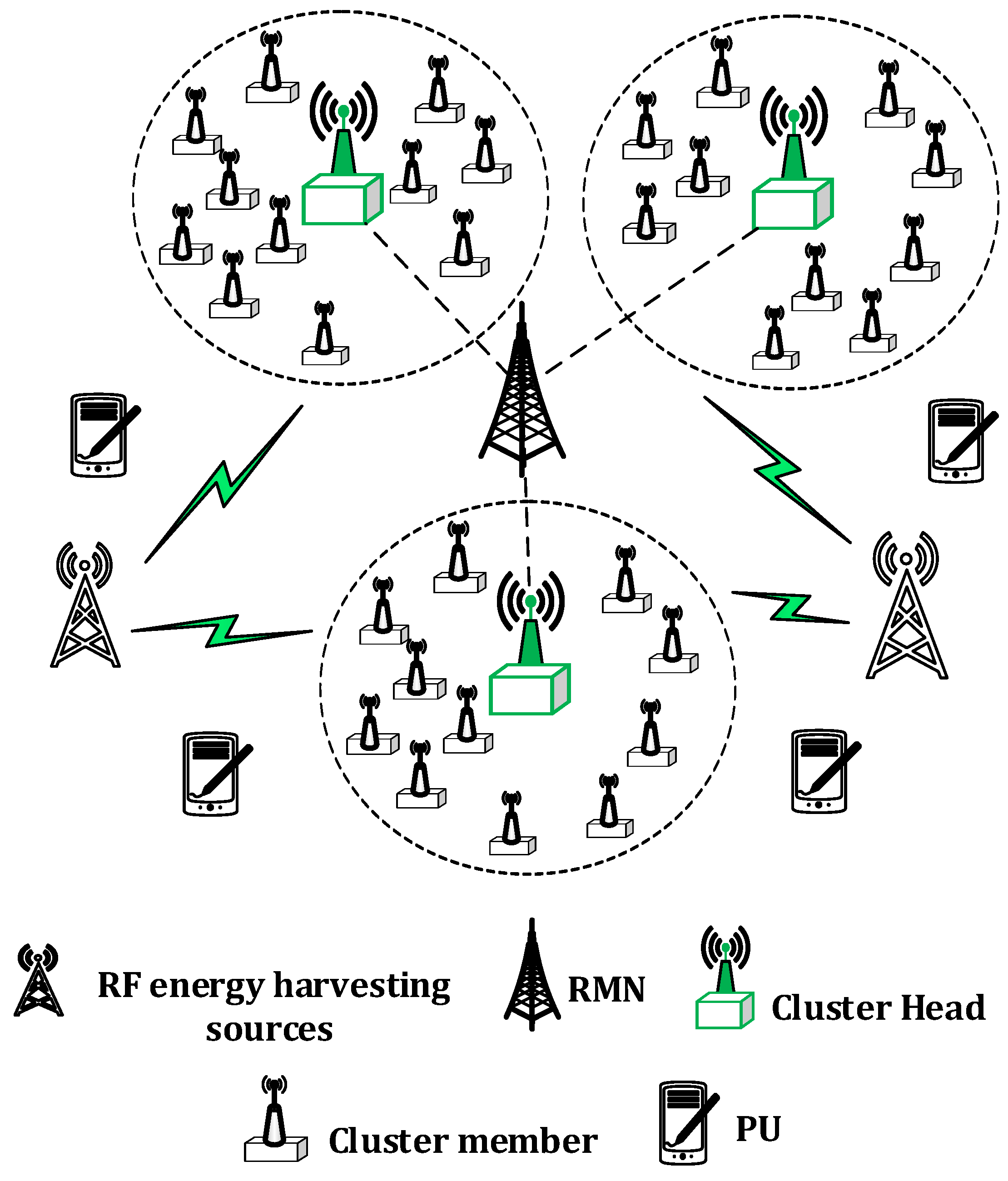
An IoT framework is presented with a focus on energy efficiency, energy balancing and QoS. To achieve energy efficiency, a scheme is developed to assign RF sources to IoT devices in such a way that RF devices can harvest the energy up to the maximum.
A clustering mechanism is introduced to cluster the IoT devices in a close proximity, and a cluster head (CH) selection strategy is proposed for that cluster. The cluster-member with the highest residual energy is selected as a CH to balance the energy consumption among the IoT devices in that cluster.
To fulfill the QoS requirements of IoTs, a novel integer linear program (ILP)-based channel-allocation scheme is presented to allocate the best possible channels to IoT devices during the reporting process.
To evaluate the performance of the proposed framework, exhaustive simulations are carried out by varying different parameters (e.g., number of channels, the number of devices, harvesting sources, etc.).
The rest of the paper is organized as follows.
Section 2 presents the related work in the domain of cluster head selection, node-source association and channel allocation.
Section 3 describes the system model.
Section 4 describes three proposed schemes. Simulation results are presented in
Section 5. Finally,
Section 6 concludes the findings and sets the future directions.
2. Related Work
A smart city is a vision for the efficient management of resources such as water, electricity, transport and parking, the lights of roads and the parks, the supervision and monitoring of hospitals and schools, etc. The IoT network is anticipated to be the key for the realization of this kind of smart city [
7]. For example, for the efficient use of water resources, the city water management department should be able to access the weather forecast information so that it can hold the process of watering plants based on the rain forecast to save a significant amount of water [
8,
9]. We consider that our proposed IoTs framework is an integral part of the smart city, which monitors an environment and routs the monitored data to a central place for better management of the city. IoT devices are usually characterized as energy-constraint devices, therefore, RF energy harvesting (RF-EH) is an alluring solution for addressing the energy limitations of these devices [
10,
11,
12,
13,
14]. RF-EH can be classified into two types: (1) in-band harvesting and (2) out-of-band harvesting. The authors in [
15,
16] presents in-band harvesting schemes, whereas the schemes in [
17,
18] present out-of-band energy harvesting for WSNs. In [
19,
20], RF-EH mechanism is described for cognitive radio networks (CRNs). In [
21,
22,
23,
24,
25], the authors also present the RF-EH mechanism for CRNs, but RF sources are placed differently in terms of their geometrical distributions. However, all of these schemes consider only a single RF source for the harvesting process, which lacks the efficient use of RF sources and also ignores the throughput and energy balancing aspects of the network. In addition, these schemes lack in achieving energy-balancing and QoS.
Usually, a large number of IoT devices are deployed in a close proximity to report a certain event. If all the IoT devices report their data to sink directly, this may result in the wastage of their energy. Therefore, a clustering mechanism is adopted to preserve the energy of the IoTs network. Further, the entire communication between IoT devices and sink is governed via CH. In this case, the energy of the CH may become depleted very sharply, which may limit the lifetime of the IoTs network. Therefore, a dynamic CH selection method for energy balancing is required to balance the energy among IoT devices in the IoTs network [
26,
27,
28,
29,
30,
31]. The authors in [
27,
28,
29] presents a clustering mechanism for preserving the energy of WSNs, but they assume a fixed CH. Although [
30,
31] present a CH selection strategy for balancing the energy among nodes in WSNs, they do not consider that the sensors are harvesting energy from RF sources. Therefore, their work is not suitable for the energy-harvested IoTs network due to the dynamic energy variations in the residual energy of the IoT devices. Thus, in this paper, we present a clustering mechanism along with CH selection for energy balancing for the RF-EH IoTs network.
The IoT network consists of a massive number of devices. Each IoT device may have different requirements in terms of throughput. However, the available spectrum is very limited. Therefore, to support such a massive number of devices and to provide them their desired throughput, a highly spectral efficient technique is required to address this issue. A possible way for accomplishing this is to extend the operating frequency using cognitive radio (CR) technology [
32,
33,
34,
35]. The CR is an intelligent radio that learns, decides and reconfigures itself according to the available portion of the spectrum [
36]. There are two kinds of users in CRNs: (1) primary users (PUs) and (2) CR users.
In CRNs, the CR users perform communication in an opportunistic manner on a portion of the spectrum not utilized by the PU [
37,
38]. Without the loss of generality, we use the same terminologies and consider the IoT devices as CR-based devices, which opportunistically access the spectrum band for their transmission. Jain et al. [
38] present a channel-scheduling algorithm for RF energy-harvesting networks to reduce the outage probability of PUs and secondary users (SUs). However, this scheme uses only PUs as a harvesting source. In [
39], the authors present a similar approach to [
38], but they analyze the results in terms of the efficiency of RF harvesting mechanism. In [
40,
41,
42], the authors extend the work in [
39] by allowing the CR users to also harvest from other ambient RF sources in addition to PU. However, this scheme is aimed at reducing the power consumption but ignores the throughput demands of CR users. Similarly, the work of [
43,
44,
45,
46] targets the energy efficiency of CR users, but they do not consider the PU activity. Also, all of the aforementioned schemes [
37,
38,
39,
40,
41,
42,
43,
44,
45,
46] ignores the availability of the channels due to their lack in consideration of PU activity. To illustrate the performance gain of our proposed scheme, we compare the greedy and random schemes with the proposed RF source association and channel-sharing mechanisms [
34,
47]. In a random association mechanism, the regional manager node (RMN) randomly associates IoT device
i with probability 1/
and RF source
j with probability 1/
. Similarly, other IoT devices and RF sources are associated with the same procedure. Similarly, the greedy scheme performs association of IoT device
i with RF source
j, which results in the highest harvesting energy. After association, that IoT device and RF source are marked as associated and they are removed from the list. The same procedure is repeated for other IoT devices and RF sources. For channel-sharing scheme, we use the same procedure for random and greedy schemes but in the context of channel sharing.
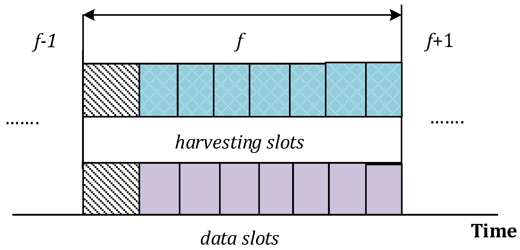
5. Performance Evaluation
This section presents the simulation results of the proposed association, clustering, CHs selection and optimal channel-allocation schemes. Furthermore, this section also compares the proposed schemes with existing ones.The performance metrics selected for evaluation are the (1) average harvesting energy; (2) successful reporting probability (SRP); and (3) number of alive nodes in the network. The performance of the proposed scheme is compared by varying the distance (meters), number of frames, PU activity, number of available channels, primary harvesting sources, secondary harvesting sources and IoT devices. The Monte Carlo simulation model is adopted to get average results for 500 different iterations. Matlab’15 is used to acquire simulation results. Although the given simulation results are equally valid for more generic cases with the higher density of IoT devices, we present the simulation results for an environment where
IoT devices are operating in a geographical area of size 1000 × 1000 m
2. For the association mechanism, we use a heuristic algorithm for IoT devices and plot the bipartite and maximum edge biclique graphs. The CHs are selected on a rotational basis using the residual energy of the nodes as selection criteria. Four heterogeneous RF sources are located at (
,
,
and
. For average idle-time computation, the PU history is maintained for Z=10 frames and the average value is computed over these 10 frames. We assign weight is in descending order from recent to old frames. The noise power spectral density is
dBm/Hz and the bandwidth of the channels
W is selected from a range of 1∼8 MHz. The rest of the important simulation parameters are shown in
Table 3.
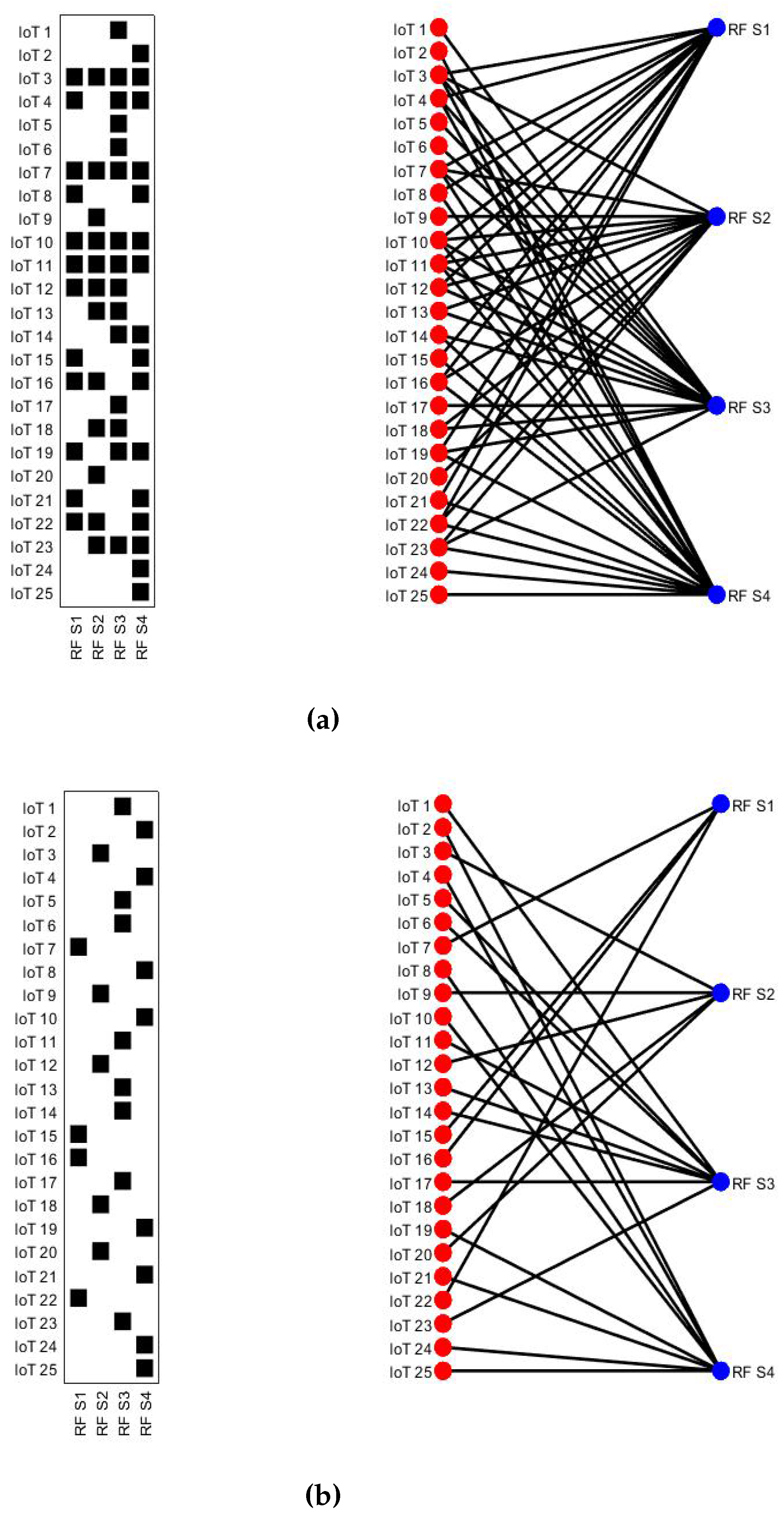
Figure 3 shows IoT devices and primary RF harvesting sources operating at [700 900 1800 2100] MHz , respectively (for proof of concept, we consider only
IoT devices and
primary RF sources. However, our results are equally valid even for a very high density of IoT devices and available RF sources). The transmission power of each primary RF source is considered to be 46 dBm. The distance of IoT devices varies from 5∼500 m within the sensing field.
Figure 3a depicts the bipartite graph where each edge between IoT device and RF source indicates that an IoT device can harvest energy from that particular source. However, this bipartite graph is showing the many-many relationship. For optimal harvesting, we find a biclique graph using proposed heuristic Algorithm 1 which converts a many-many relationship into a one-many relationship where each edge shows the optimal relationship between the IoT device and RF source as shown in
Figure 3b. For example, the IoT devices
are associated with RF harvesting source
to maximize the overall harvesting energy of the IoTs network.
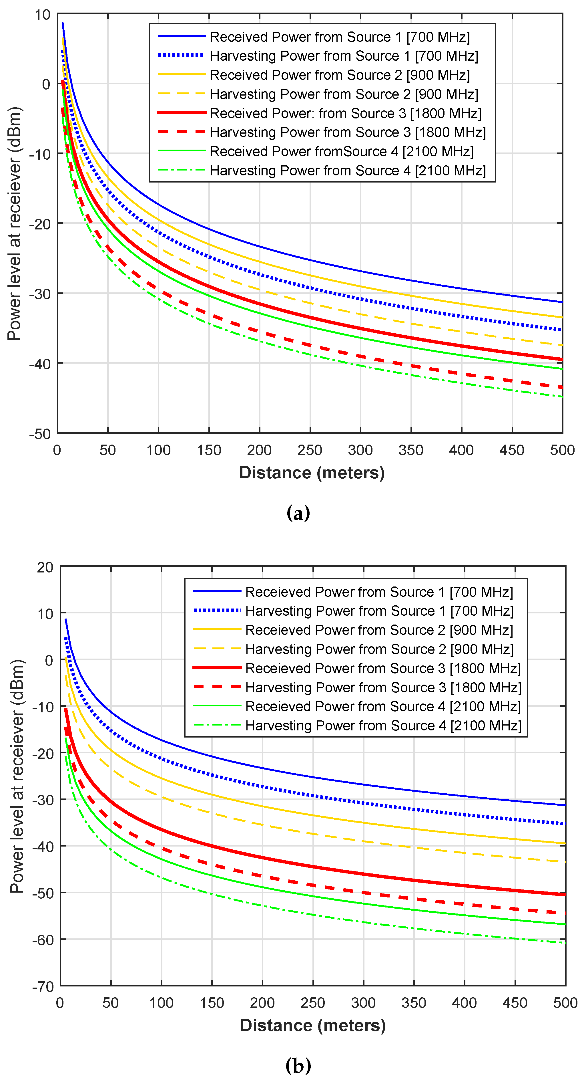
Figure 4 illustrates the average received and harvesting powers from different RF sources operating at [700 900 1800 2100] MHz, respectively. The variations in received and harvesting powers are plotted by varying the distance of nodes from 0∼500 m. The rest of the simulation parameters are the same as that mentioned for
Figure 3. In this simulation result, we try to depict the heterogeneity of RF sources in terms of operating frequency bands and transmission powers. In
Figure 4a, we use the same power of 46 dBm, whereas in
Figure 4b, we use the power of [46 40 35 30] dBm for [700 900 1800 2100] MHz sources, respectively. It is clear from the two results that the highest energy can be harvested from that primary source for at 700 MHz source with 46 dBm of power and harvesting energy decreases as we move to the higher spectrum. Furthermore, the overall harvesting energy decreases with a decrease in the transmission power or an increase in the distance. One important thing is the difference (i.e., the difference between solid and dashed or dotted lines) between the received power and the harvesting power. This is due to the lower harvesting efficiency
η of the receiver.
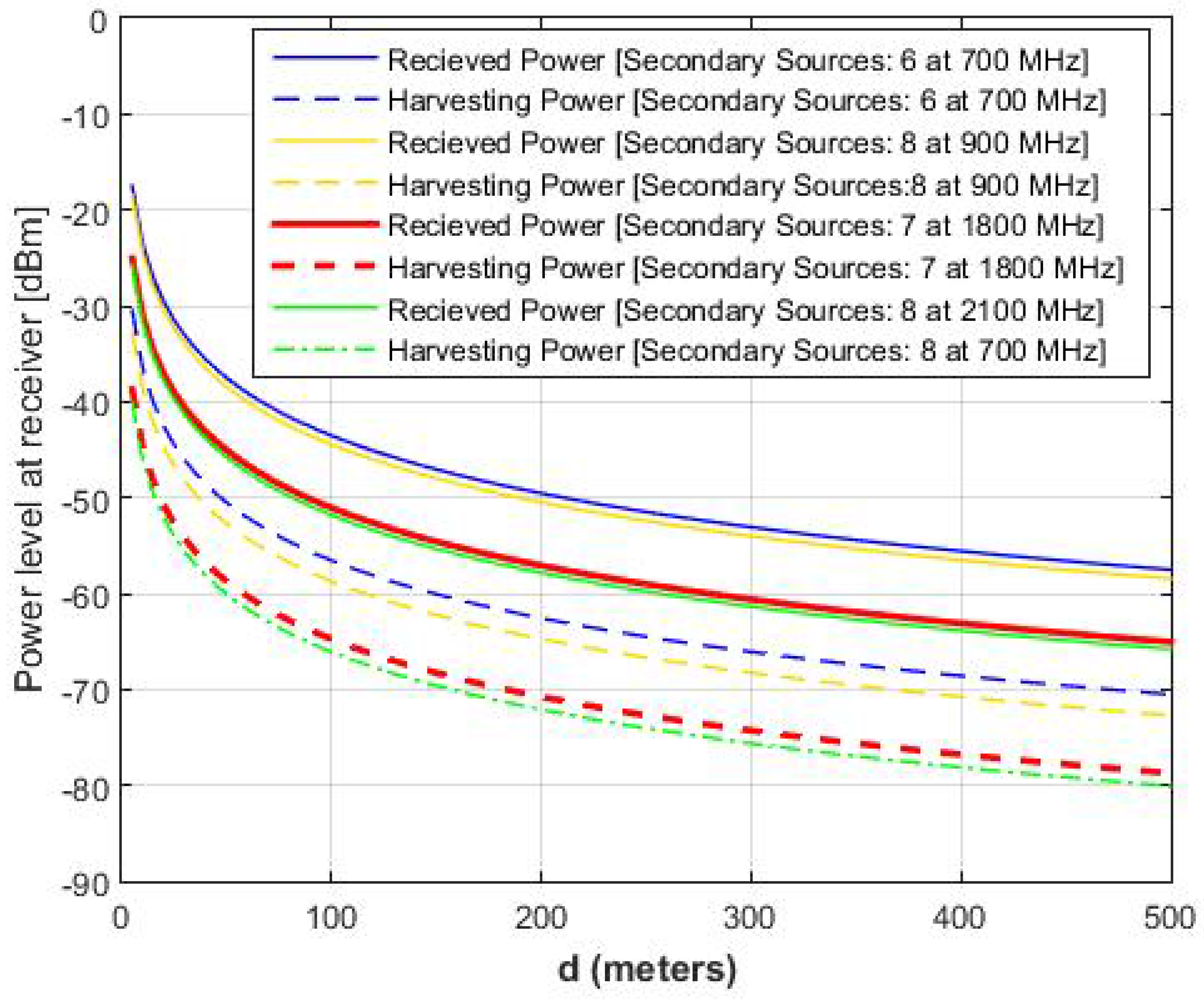
Similarly,
Figure 5 illustrate the received and harvesting power from different secondary RF sources at [700 900 1800 2100] MHz with
. The result shows the decline in the harvesting efficiency with an increase in the distance. Compared to the harvesting power of the primary RF sources shown in
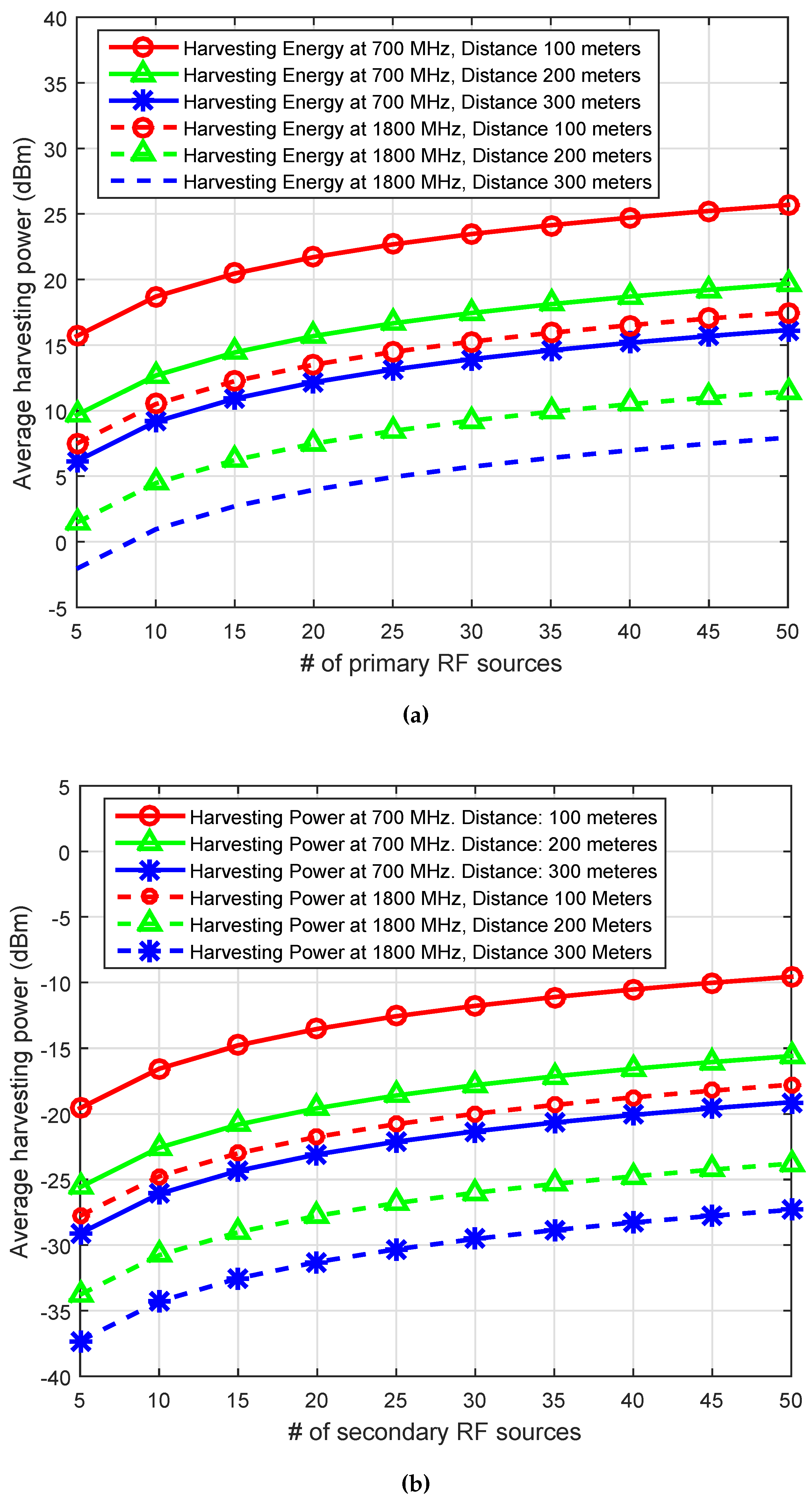
Figure 4, the average harvesting power from secondary RF sources is 20 dBm lower than the harvesting power from primary RF sources. To provide further insight into the harvesting power or energy, we vary the number of primary RF sources (i.e.,
= 5∼50 (
Figure 6a)) and secondary RF sources (i.e.,
= 5∼50 (
Figure 6b)), and we plot the average received and the harvesting powers at frequency of [700 1800] MHz and the distance of [100 200 300] m. Both results show an increase in the harvesting power with an the increase in harvesting sources. However, there is a sharp decline with the increase of the distance between the RF source and IoT devices.
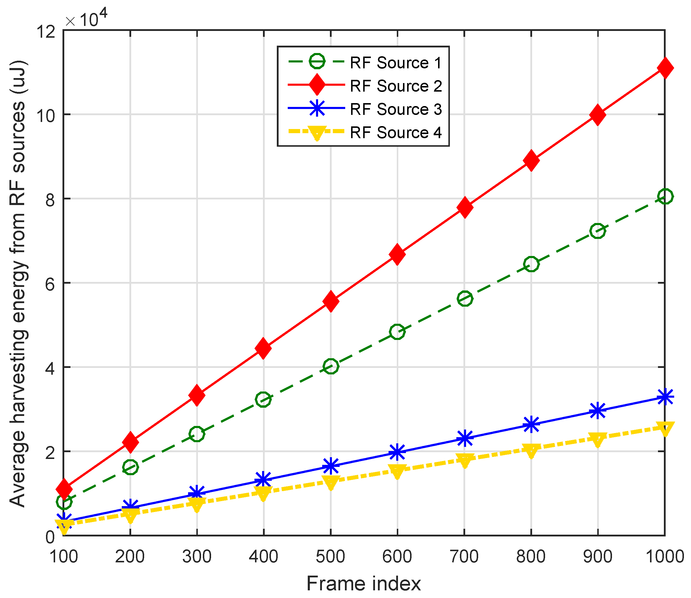
Figure 7 illustrates accumulated harvesting energies from different primary sources across different frame indexes. It is clear from the simulation result that accumulative harvesting shows a linear increase with the increase of the frames. The IoT devices belong to a cluster that is near the RF source transmitting at a 700 MHz band with power 46 dBm which are harvesting more powers as compared to the other IoT devices that belong to the cluster of RF sources operating at [900 1800 2100] MHz, respectively.
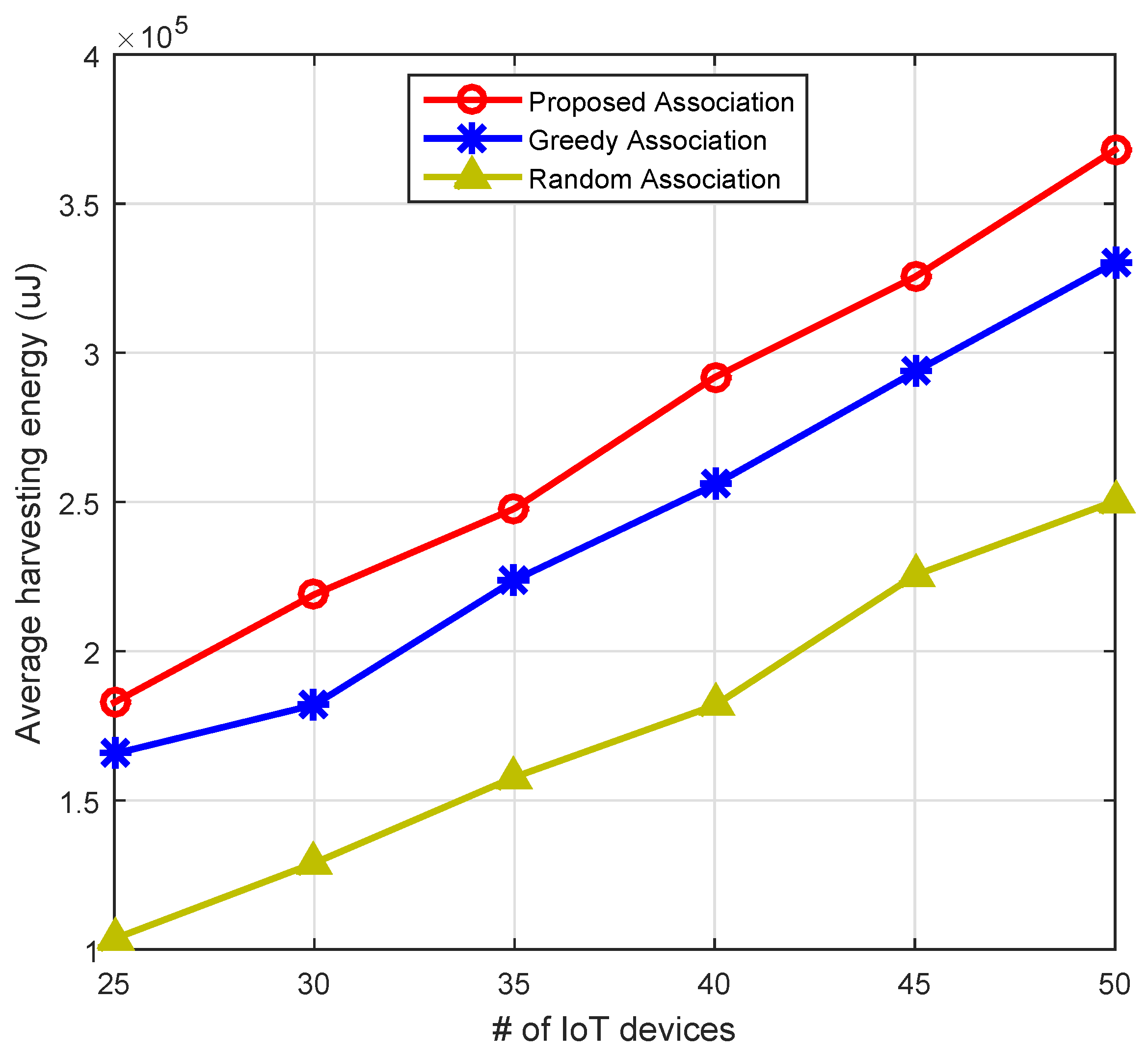
Figure 8 compares the proposed association mechanism with greedy and random approaches. The comparison is drawn based on the average harvesting energy from primary and secondary RF sources. It is clear from the result that the proposed heuristic algorithm of association optimized the RF harvesting energy compared to the greedy and random association mechanisms. For example, with 40 IoT devices, the proposed association mechanism harvests 12.4% and 37.69% higher energy, respectively, as compared to the greedy and random association approaches. Hence, our proposed biclique graph-based association scheme is the most suitable for IoT devices.
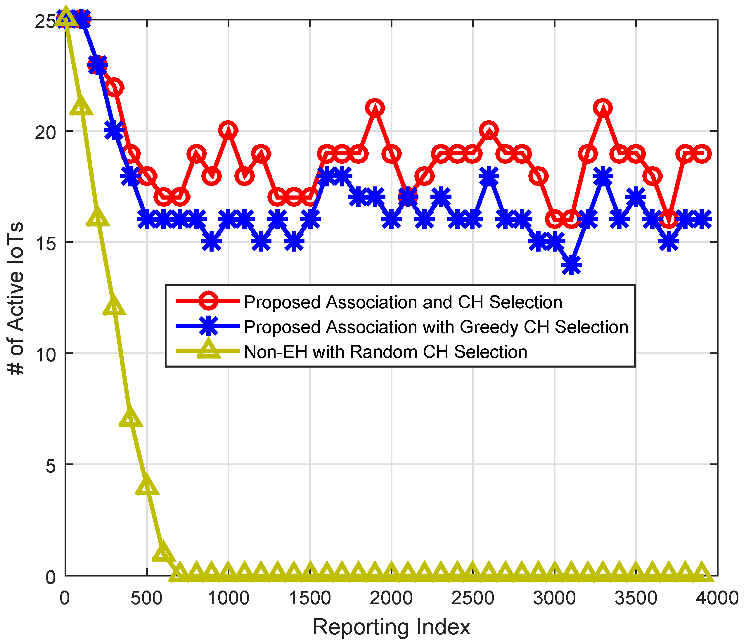
Figure 9 illustrates the advantage of the energy efficient association and energy-aware CH selection scheme. We plot the number of active IoTs at various reporting indexes.
An IoT device is said to be active if its residual energy is equal or more than 50% of its initial energy. There are two noticeable things about the pattern of the results. First, the proposed scheme shows better performance as compared to the other schemes. Second, the proposed EH and association schemes switch the nodes between an active and nonactive state; hence, the network will remain alive for a longer duration. With the proposed CH selection mechanism, there are a higher number of active IoTs at any given frame index as compared to the greedy and random CH selection schemes. For example, consider frame index 500; the proposed scheme shows 12% and 77.88% higher alive IoTs, respectively, compared to the greedy and random CH selection schemes. Hence, with the proposed association and CH selection mechanisms, the network can remain alive longer and more IoTs can participate in the reporting process.
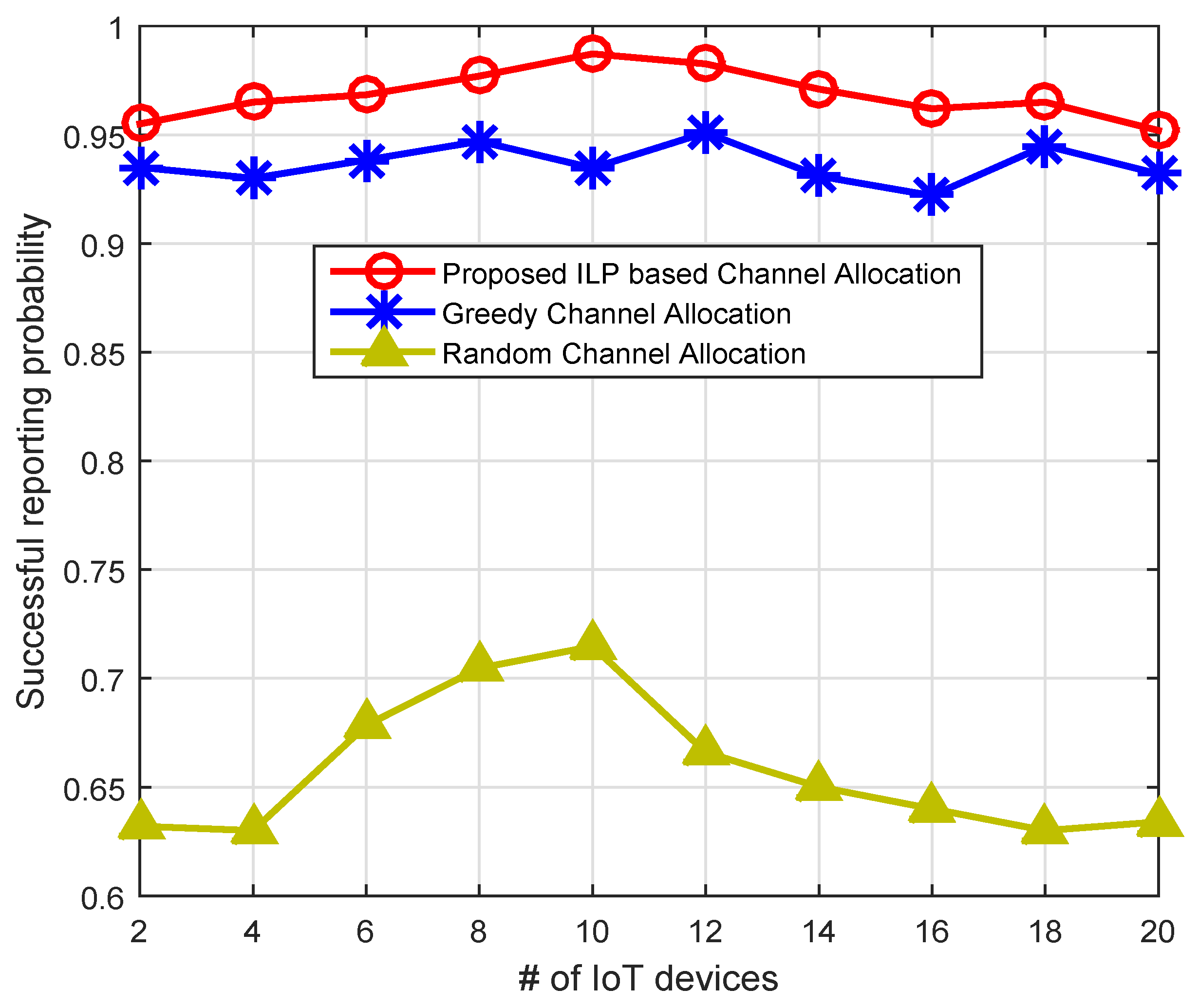
Figure 10 shows the successful reporting probability (SRP) using our residual energy and PU activity-aware throughput and QoS optimization scheme in comparison with the greedy and random channel allocation schemes. A reporting is considered to be successful if the residual energy of the node is higher than the 50% of its initial energy, and the channel satisfies the minimal QoS criteria. The PU activity also reduces SRP if it arrives in the middle of the reporting process. The greedy channel allocation (GCA) scheme selects IoT device
i and allocates channel
k, which has the highest value of the objective function as shown in Equation (13). After channel allocation, the GCA marks that IoT device and channel as assigned and removes them from the pool of channels and IoT devices. Then, the same procedure is repeated for the rest of the nodes until all channels are allocated to IoT devices. The random channel allocation (RCA) scheme randomly picks the IoT device
i with probability
and channel k with probability
, and channel allocation is performed for reporting process. Similarly, other IoT devices will get channel with the same procedure. The proposed energy and PU activity-aware throughput and QoS optimization scheme shows significantly better successful reporting probability compared to GCA and RCA. For example, with 10 IoT devices, the proposed scheme shows 27.6% and 5.31% better SRP as compared to the RCA and GCA schemes. Similarly, in
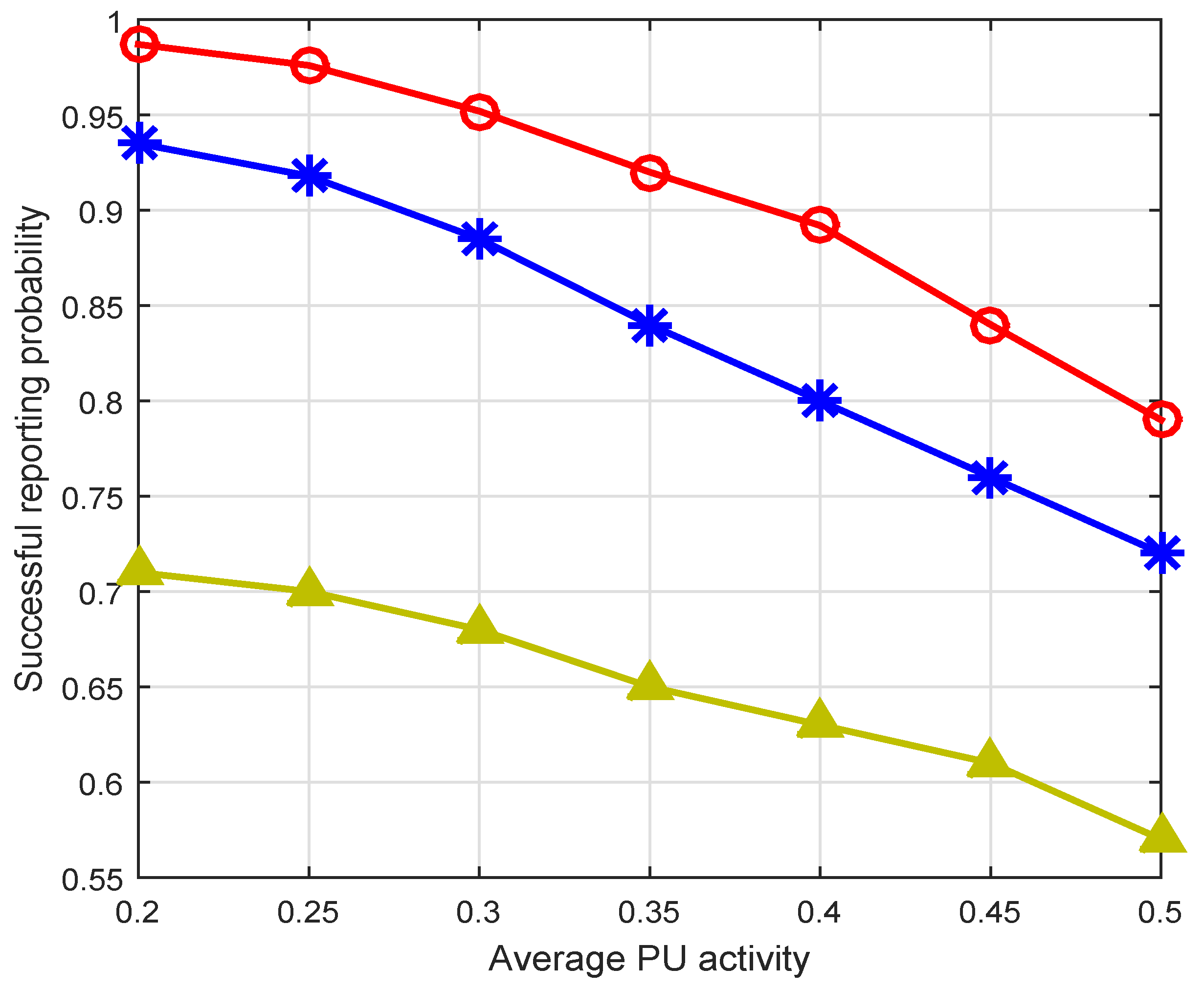
Figure 11, we plot the SRP against different PU activity (i.e., different PU arrival rate). The SRP declines exponentially with the increase of the PU activity for all three schemes. However, the proposed channel allocation scheme shows up to an 8% and 30% better SRP compared to the GCA and RCA schemes.


