1. Introduction
Since the concept of the Brillouin time domain analyzer (BOTDA) was first proposed in 1989 [
1], enormous research efforts have been devoted to this technique, due to its capability of distributed monitoring of temperature and strain change along the fiber. By scanning the pump-probe frequency difference, the Brillouin gain spectrum (BGS) can be re-constructed to determine the distribution of Brillouin frequency shift (BFS), and hence the temperature and/or strain information along the fiber can be retrieved. In recent decades, driven by the increasing demand for structural health monitoring by distributed temperature and/or strain sensing in civil, transportation, aviation, and military applications, many works have been done to enhance the system performance in terms of spatial resolution and sensing range [
2]. However, it has been shown that it is difficult to extend the sensing range while maintaining a high spatial resolution, since the BOTDA system suffers from pump depletion [
3], non-local effects [
4], modulation instability [
5], and other nonlinearities. Due to these limitations, the signal-to-noise ratio (SNR) of the Brillouin time-domain signal at the far end of the fiber is severely degraded, especially for long-range sensing at high spatial resolution, leading to inevitable large BFS uncertainties and temperature/strain error.
In recent years, to enhance the SNR of BOTDA systems, various techniques and schemes have been established [
6,
7,
8,
9,
10,
11,
12,
13,
14,
15,
16,
17,
18,
19]. Coherent detection has been applied for Brillouin signal detection to improve the SNR [
7,
8] and to obtain additional Brillouin phase information for reduction of the non-local effects [
9]. Optical coding techniques have been employed to achieve highly sensitive BOTDA systems without sacrifice of the spatial resolution [
10,
11]. Moreover, in order to reduce the pump loss and depletion, distributed Raman and Brillouin amplification has been applied in BOTDA systems [
12,
13]. Further works have combined the coding technique with Raman amplification in BOTDAs to extend the sensing range with less system performance degradation [
14,
15,
16]. More recently, different kinds of offline signal processing techniques such as image processing [
17] and artificial neural networks [
18] have been deployed to significantly enhance the sensor performance.
Recently, we have reported a novel scheme named Bi-Directional BOTDA (BD-BOTDA) system [
19] to extend the sensing range of the system but without introducing any complicated components. In this paper, the BD-BOTDA system is further demonstrated with optimized parameters, achieving distributed sensing over 80 km at a spatial resolution of 2 m and a BFS uncertainty of ~0.44 MHz. Unlike the preliminary results in [
19], here we also analyze the system performance and compare it with that of the conventional unidirectional BOTDA. The results show that, at the same sensing range (e.g., ~80 km), the BD-BOTDA system has a performance level comparable to the unidirectional BOTDA with half of the sensing range (e.g., ~40 km) and doubles the measurement speed. Moreover, the proposed technique shall provide an alternative approach to extending the sensing range. This technique does not compete with other existing techniques, such as Raman amplification [
12], Brillouin amplification [
13], and coding techniques. Thus, it is expected that the sensing range can be further enhanced by combination of our approach with other existing techniques.
2. Principle and Experimental Setup
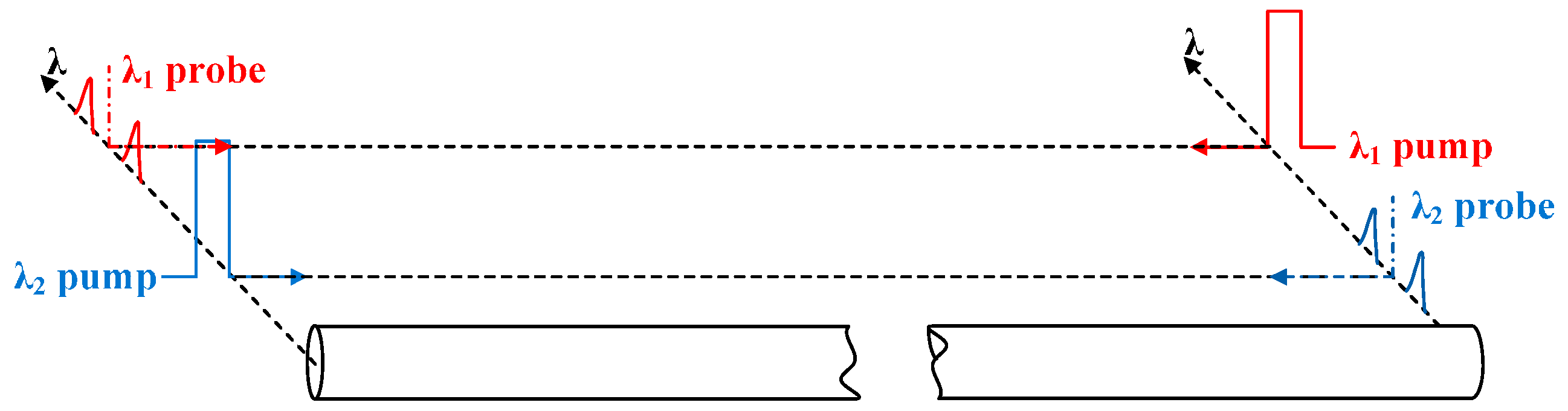
As shown in
Figure 1, our BD-BOTDA system employs two pump-probe pairs whereby each pair has a particular wavelength. Each pump-probe pair has a pulsed pump and a continuous wave (CW) probe, which are each injected from opposite ends of the fiber under test (FUT) and serve as one of the two channels of our BD-BOTDA system. For each channel, one half of the whole fiber span is used as the sensing fiber, while the other half only carries the probe signal to the sensing fiber. The two channels simultaneously measure the Brillouin signals along each half of the FUT, and the temperature or strain information along the whole FUT can hence be obtained by combining the results collected from the two channels of the BD-BOTDA system. If the system parameters (e.g., pump and probe powers) involved in the Brillouin interaction in the sensing fiber are optimized for each channel, both the SNR performance and the measurement time of the BD-BOTDA system shall be the same as a unidirectional BOTDA system with half of the sensing range. That means the system performance becomes better while the measurement speed is doubled compared with the unidirectional BOTDA system of the same sensing range. Compared with the unidirectional BOTDA system, some extra components are necessary. However, a number of key components can be shared by the two wavelength channels.
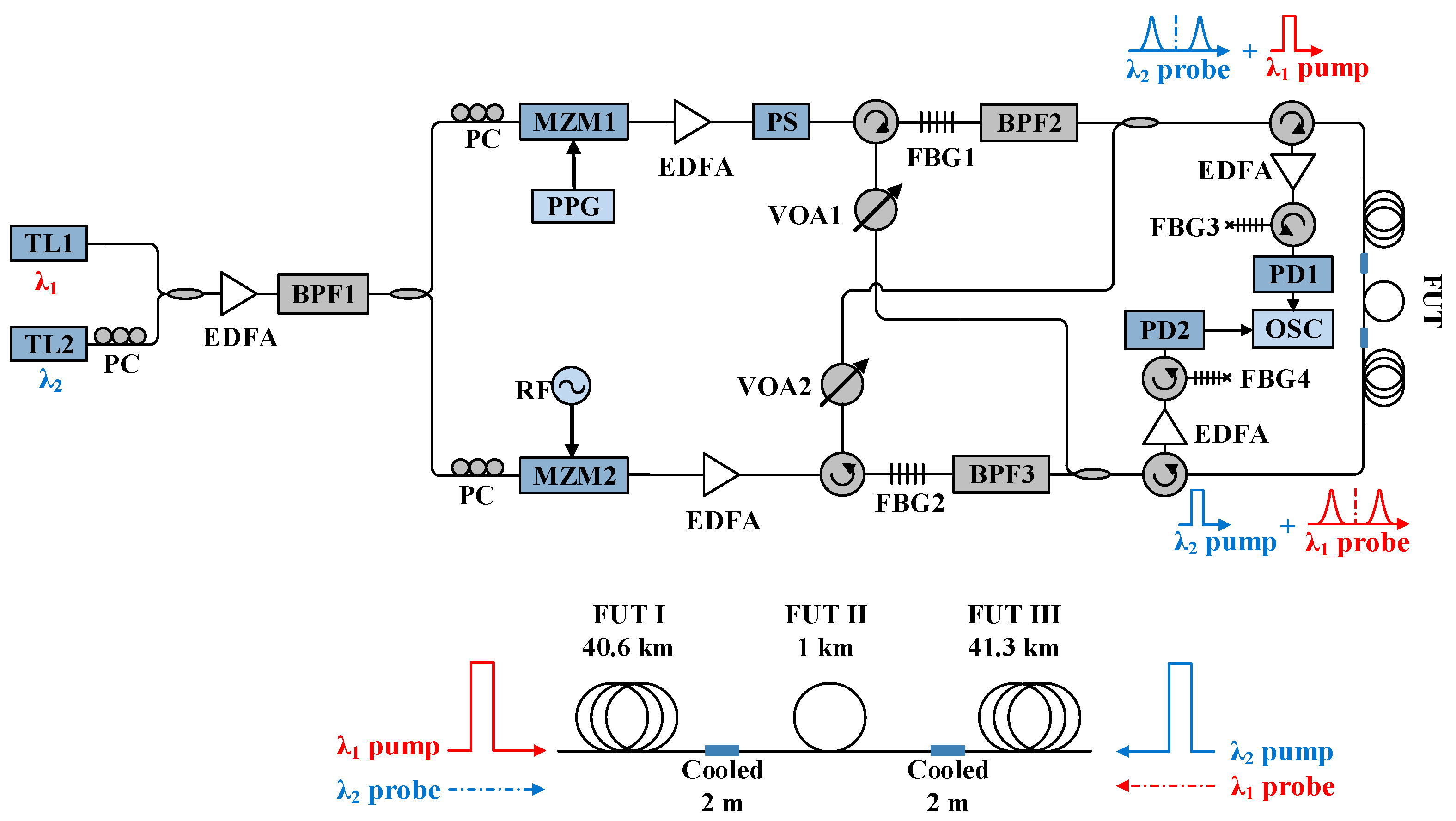
The experiment setup for the BD-BOTDA system is illustrated in
Figure 2. Two tunable lasers (TL1 and TL2, Emcore Corporation, Alhambra, CA, USA) with the wavelengths of
λ1 (~1550 nm) and
λ2 (~1552.8 nm) are employed for the two channels of BD-BOTDA, respectively. The output of TL2 passes through a polarization controller (PC) to make its polarization aligned with TL1 before they are coupled together with a 50/50 coupler. An erbium-doped fiber amplifier (EDFA, Amonics Ltd., Kowloon, Hong Kong, China) is used to boost the optical power, and the following band pass filter (BPF1) with a bandwidth of 5 nm is used to filter out the amplified spontaneous emission (ASE) noise. Then, the lightwaves are divided into two branches for the generation of two pairs of pulsed pump and CW probe. The upper branch is modulated by utilizing a Mach–Zehnder modulator (MZM1, iXBlue, Besançon, France) and a pulse pattern generator (PPG, Anritsu Corporation, Atsugi-shi, Kanagawa, Japan) to produce 20 ns pump pulses at both
λ1 and
λ2. The EDFA in the upper branch is used to boost the pulse peak power and the polarization scrambler (PS, General Photonics Corporation, Chino, CA, USA) is used to minimize the polarization-dependent fluctuation of the Brillouin signal. A circulator together with a fiber Bragg grating (FBG1) having a reflection band at
λ2 is applied to separate the two channels of pump pulses. The following BPF2 with a bandwidth of 1 nm is employed to minimize the residual ASE noise and residual pulsed pump at
λ2. A variable optical attenuator (VOA1) is inserted to balance the pulse peak power at the two wavelengths. On the other hand, the lower branch experiences the carrier-suppressed modulation at a frequency around Brillouin frequency shift (BFS) to generate the double sideband probe signals at the two wavelengths. The carrier suppression ratios for both wavelengths are measured to be over 30 dB. The EDFA in the lower branch are employed to control the power of the probes. Another circulator and FBG2 are used to separate the probe signals at
λ1 and
λ2 as two channels of the BD-BOTDA system. Similar to the pump branch, BPF3 and VOA2 play the same role as BPF2 and VOA1. Then, in each direction, a 50/50 coupler is utilized to combine a pulsed pump at
λ1 (or
λ2) together with a CW probe at
λ2 (or
λ1), and the outputs of the two couplers are delivered to the FUT from both ends. At the receiver side, the probe signals at
λ1 and
λ2 are amplified by EDFAs, and the corresponding lower sideband signals are selected by using circulators and FBGs (FBG3 and FBG4) for detection. The 3 dB bandwidth of the FBG3 and FBG4 is ~10 GHz. The selected signals at
λ1 and
λ2 are detected by two photodetectors (PD1 and PD2, Newport Corporation, Irvine, CA, USA) simultaneously and then collected by using a two-channel oscilloscope (OSC, Tektronix China Ltd., Shanghai, China).
The FUT is composed of three spans of single-mode fibers (Sumitomo Electric Lightwave Corp., Raleigh, NC, USA): FUT I (40.6 km), FUT II (1 km), and FUT III (41.3 km), as shown in
Figure 2. FUT II is placed at the middle of the other two. Hence, FUT I is measured with the
λ1 channel, while FUT III is measured with the
λ2 channel at the same time. The last 2 m fibers of FUT I and FUT III are cooled down to 0 °C by using an ice-water bath, while the remaining fibers are kept under room temperature (about 24 °C).
During the experiment, the frequency is scanned from 10.73 to 10.93 GHz and 1000 averaging times are adopted on the oscilloscope to minimize the noise. Note that the BFS is related to the wavelength of the pulsed pump, thus in order to avoid the increase of frequency scanning range, the wavelength difference of the two channels of the BD-BOTDA system is chosen to be around ~3 nm, which only produces about 20 MHz BFS difference and avoids the interference between the two channels at the same time. At the same time, the 3 nm wavelength difference between the two channels also provides sufficient phase mismatch to minimize the effect of four-wave mixing (FWM) between the two channels. Moreover, only one pulse exists inside the fiber for each channel, which reduces the effective interaction length for FWM to take place.
To optimize the performance of each channel, the powers of the pump and probe signals have been carefully controlled. The extinction ratio of the pump pulses at both wavelengths is measured to be over 40 dB, and the peak power, limited by modulation instability (MI) [
5], is set to be 22 dBm, which is similar to that of a conventional unidirectional system. In comparison with the conventional setup, the probe lightwave in each channel will propagate through the carry-over fiber of about 40 km, and suffers about 8 dB attenuation before entering into its sensing fiber. Considering this fact, the average power of each probe lightwave launched into the FUT is ~2 dBm. By doing this, when it enters into the sensing half, the power is maintained at about −6 dBm, and the non-local effects can be avoided [
3]. Under those power settings, the input powers of the pump and probe signals for sensing in each channel of the BD-BOTDA system are similar to those in conventional BOTDA system with a 40 km sensing range, resulting in the SNR performance of the BD-BOTDA system comparable to the conventional BOTDA system with half of the sensing range. Hence, with respect to 80 km sensing range, an SNR improvement of 8 dB can be expected using the approximated model in [
20] when compared with the conventional system of the same sensing range. It should be noted that we have monitored the optical spectrum of the signals from both fiber ends and have not observed any FWM phenomena at the power levels used in our experiment.
3. Experiment Results and Analysis
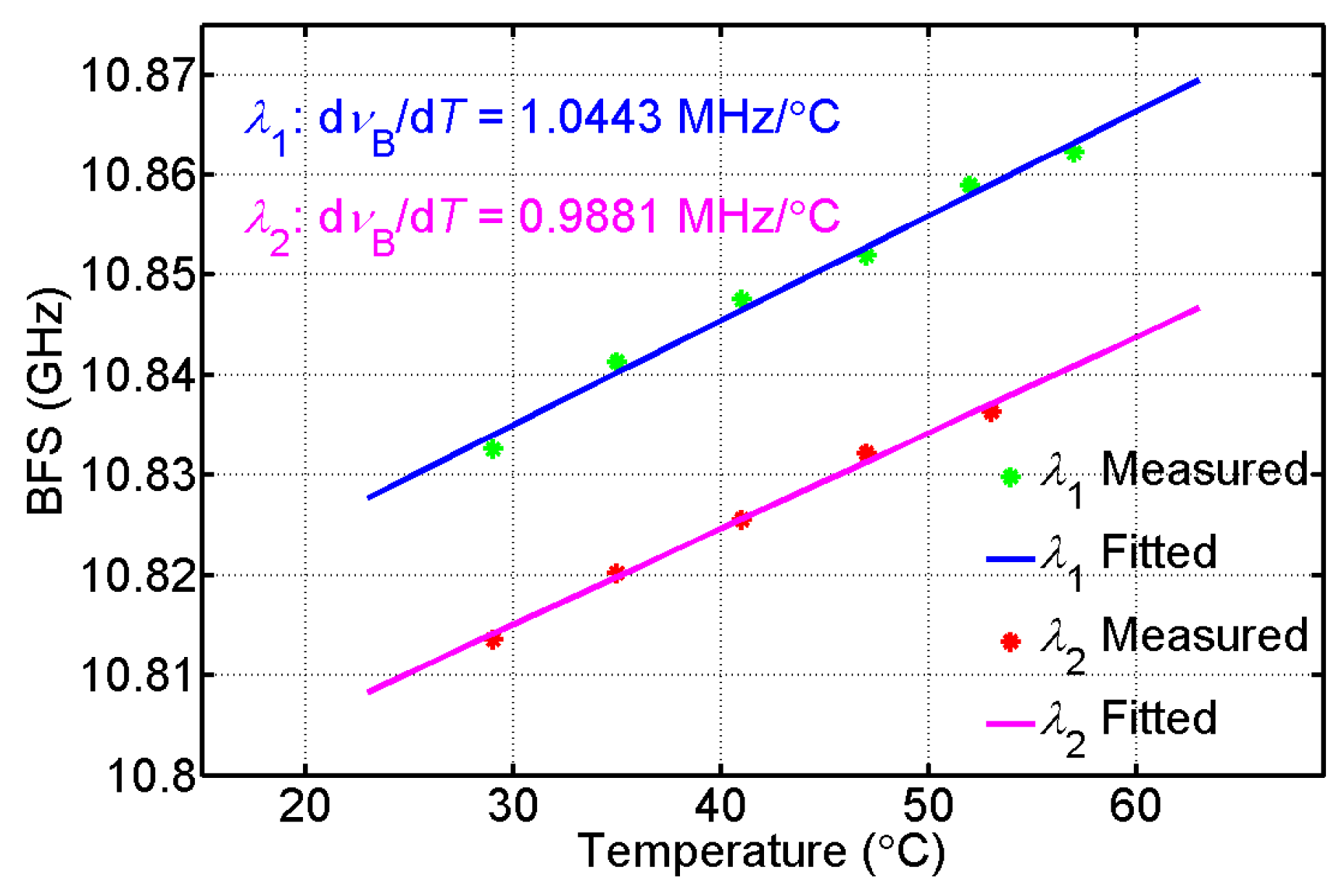
Before we start the use of the BD-BOTDA system for sensing, we first calibrate the temperature coefficients of BFS at both wavelengths
λ1 and
λ2. The results are given in
Figure 3, showing linear relationships between BFS and temperature. The temperature coefficients at
λ1 and
λ2 are 1.0443 and 0.9881 MHz/°C, respectively, which will be used in the calculation of temperature distribution along the FUT.
Then, we apply the BD-BOTDA system for distributed temperature sensing of the FUT.
Figure 4 shows the BGS distribution versus distance for both the
λ1 and
λ2 channels. As mentioned above, each channel is responsible for the measurement of one half of the FUT, and
Figure 4a shows the distributed BGS measured at the
λ1 channel along FUT I and FUT II, while
Figure 4b plots the BGS distribution measured at the
λ2 channel along FUT III. For both channels, the BGS distributions along the last ~10 m of FUT I and FUT III are also illustrated at the right side of
Figure 4, showing clearly the cooled 2 m fibers in FUT I and FUT III.
By using the temperature coefficients calibrated in
Figure 3, we obtain the temperature distribution along the FUT from the measurement of the two channels of the BD-BOTDA system.
Figure 5a,b show the corresponding temperature information for the final meters of FUT I and FUT III. The fiber section cooled down to 0 °C has been successfully detected by each wavelength channel. The results also indicate a spatial resolution of ~2 m (corresponding to 20 ns pump pulses used in our experiment) in both channels of our system.
4. Discussion
In order to illustrate the advantages of our BD-BOTDA system, two SMFs of 40.6 km and 81.9 km have been measured for comparison respectively by using a unidirectional BOTDA system with almost the same parameters as those in the BD-BOTDA system. The Brillouin time-domain traces measured at the Brillouin center frequency of the SMFs are given in
Figure 6.
Figure 6a,b show the traces along 40.6 km and 81.9 km SMFs measured with the unidirectional BOTDA system, while
Figure 6c,d depict the traces of the λ
1 and λ
2 channels in the BD-BOTDA system, respectively. The four insets at the right side of
Figure 6 illustrate the contrast between the Brillouin signal (red curves) near the end of the fibers and the noise background (blue curves), from which the SNRs of the traces are calculated to be 11.57 dB, 2.83 dB, 12.10 dB, and 11.62 dB. The SNRs of the two channels in the BD-BOTDA system are almost the same as the trace SNR of the 40.6 km fiber measured with the unidirectional BOTDA, and have an SNR enhancement of over 8 dB when compared to the unidirectional BOTDA system with a sensing range of ~81.9 km. The enhanced performance is also verified by calculating the BFS distribution along the fiber.
According to the results and
Figure 6 shown above, the proposed technique shall offer a doubled sensing range while maintain the SNR at the level of the conventional BOTDA with half of the sensing distance. Moreover, when compared to the conventional BOTDA with the same FUT range, an SNR enhancement corresponding to the attenuation of the half FUT length, which is ~8 dB in our demonstration, can be achieved by employing the BD-BOTDA system.
By using Lorentzian curve fitting, the BFS distributions for the 40.6 km and 81.9 km SMFs measured with the unidirectional BOTDA are shown in
Figure 7a,b for comparison. The results measured with the
λ1 and
λ2 channels of the BD-BOTDA system are shown in
Figure 7c,d. The BFS uncertainties of the
λ1 and
λ2 channels in the BD-BOTDA system are calculated to be 0.4366 MHz and 0.4340 MHz, respectively; the ones in the unidirectional BOTDA system for 40.6 km and 81.9 km SMFs are 0.4414 MHz and 5.0162 MHz. Obviously, the BFS uncertainty of our BD-BOTDA system with a sensing range of 82.9 km is comparable to that of the unidirectional BOTDA system with half of the sensing range, and hence is much better than that of the unidirectional BOTDA system with a similar sensing range. It is worth mentioning that the BFS uncertainty of the 81.9 km SMF using the unidirectional BOTDA system suffers from a degradation of over 10 dB, rather than the expected ~8 dB degradation, compared to the case of the 40.6 km SMF. This may be because the BGS profile near the end of the 81.9 km SMF has been flattened and broadened. Note that the undistorted BGS’s measured with the BD-BOTDA system indicate that the non-local effect is negligible in our experiment thanks to the power optimization.
Based on the analysis above, the proposed technique doubles the sensing range while maintaining the same performance as a conventional BOTDA with half of the range. Moreover, it is worth mentioning that the proposed technique shows its benefits for the practical deployment of the BOTDA system. The loop configuration for most of the BOTDA systems, in which the FUT goes and comes back by the same path, makes the second half redundant for monitoring. Since the proposed BD-BOTDA technique offers the same level of performance for each half of the FUT, the redundant data collected from one half of the FUT can serve as an appropriate reference for the discrimination of temperature and strain. Therefore, by carefully deploying the FUT making half of it free from strain as reference and the other half experiencing both environmental temperature and strain, the configuration redundancy in the BD-BOTDA system can be properly used for distributed monitoring of both temperature and strain.


