1. Introduction
The types of sensors used in the localization of mobile robots include laser sensors [
1,
2,
3], visional sensors [
4,
5,
6], infrared sensors [
7], RFID (Radio Frequency Identification Devices) [
8] and ultrasonic sensors [
9,
10], which compared with other sensors is the most robust and low-cost distance detection device [
11]. The sound waves emitted by an ultrasonic sensor encompasses a fan-shaped area, the angle of which is defined as the divergence angle, and all objects that fall within this region can be detected. The distance accuracy of the ultrasonic sensor may be limited by failure to consider the divergence angle and the incidence angle, which refers to the angle between the cross-section of the ultrasonic sensor and the plane of the object being detected.
Song and Tang [
12] reduced the impact of the divergence angle on the localization accuracy of a mobile robot by the application of external and independent Kalman filtering and the use of two ultrasonic sensors and a CCD (Charge-Coupled Device) vision sensor. Noykov and Roumenin [
11] experimentally outlined an orientational probability graph for the divergence angle of an ultrasonic sensor and proposed an ultrasonic sensor edge detection method based on polaroid ultrasonic sensors. Kim and Kim [
10] put forward a dual-ultrasonic sensor overlapping area distance detection method, which effectively decreased the influence of the divergence angle on the ranging accuracy of ultrasonic sensors, allowing for the precise localization of the posture of the car-like robot. Bin Liang et al. [
13] brought forward the lateral localization method that employed two ultrasonic sensors installed on one side of the robot and considered the incident angle. Wijk and Christensen [
14] proposed the use of information fusion technology for the indoor robot localization by the recognition of the fixed object. Carinena et al. [
15] applied the novel paradigm of fuzzy temporal rules to detect doors using the information of ultrasonic sensors. Hwang et al. [
16] introduced a simple GPS system for the indoor localization of a mobile robot that consisted of one transmitter having ultrasonic and RF (Radio Frequency) and two receivers. Li et al. [
17] developed an ultrasonic sensor array heuristic controller system with group-sensor firing intervals, which was used to obtain the posture of a mobile robot in a parking space, and to ensure the ability to withstand collision and to guarantee safety parking. Kim and Kim [
18] presented the optimal arrangement of an ultrasonic sensor ring with beam overlap for high resolution obstacle detection and minimal position uncertainty of a mobile robot. Hsu et al. [
19] proposed a localization method based on the omni-directional ultrasonic sensor, which included a mobile robot carrying an omni-directional ultrasonic device as a transmitter and several ultrasonic sensors located at the vertices of a square environment serving as receivers. Lim et al. [
20] proposed a novel control architecture which enabled a robot to navigate indoor environments while avoiding obstacles and localizing its current position by using a smartphone as its brain to deal with the heavy-duty and rotating ultrasonic sensors, reducing the number of sensors needed, as well as the time of distant measurements. Currently, research in the field of mobile robot localization is typically limited to uni-directional localization, for instance, forward or lateral localization, and research on the simultaneous forward, lateral and posture localization is rare.
Previous studies to reduce the effects of the divergence angle and the incident angle of ultrasonic sensors for the localization of a mobile robot have mainly focused on filtering or compensation methods. In this paper, the improved ultrasonic ranging calculation expression is presented, which is based on the original distance detection model for ultrasonic sensors. The ultrasonic sensor scanning method described herein can be used to recognize the inclined plate and acquire the position and posture of the ultrasonic sensor relative to the framework of the inclined plate. Finally, the omni-directional scanning localization method of a mobile robot is put forth based on this scanning method.
The organization of this paper is as follows:
Section 2 analyses the affections of the divergence angle and the incidence angle on the ranging accuracy of the ultrasonic sensor, and deduces the improved algorithm expression.
Section 3 introduces the methodology of the edge detection and the recognition of the inclined plate, and is extended in the application of the omni-directional scanning localization method in
Section 4. In
Section 5, the experiments of the identification of thresholds and the actual localization of a mobile robot are implemented, and the results verified the proposed localization methodology. Finally,
Section 6 offers brief concluding comments.
2. The Divergence Angle and the Incidence Angle of an Ultrasonic Sensor
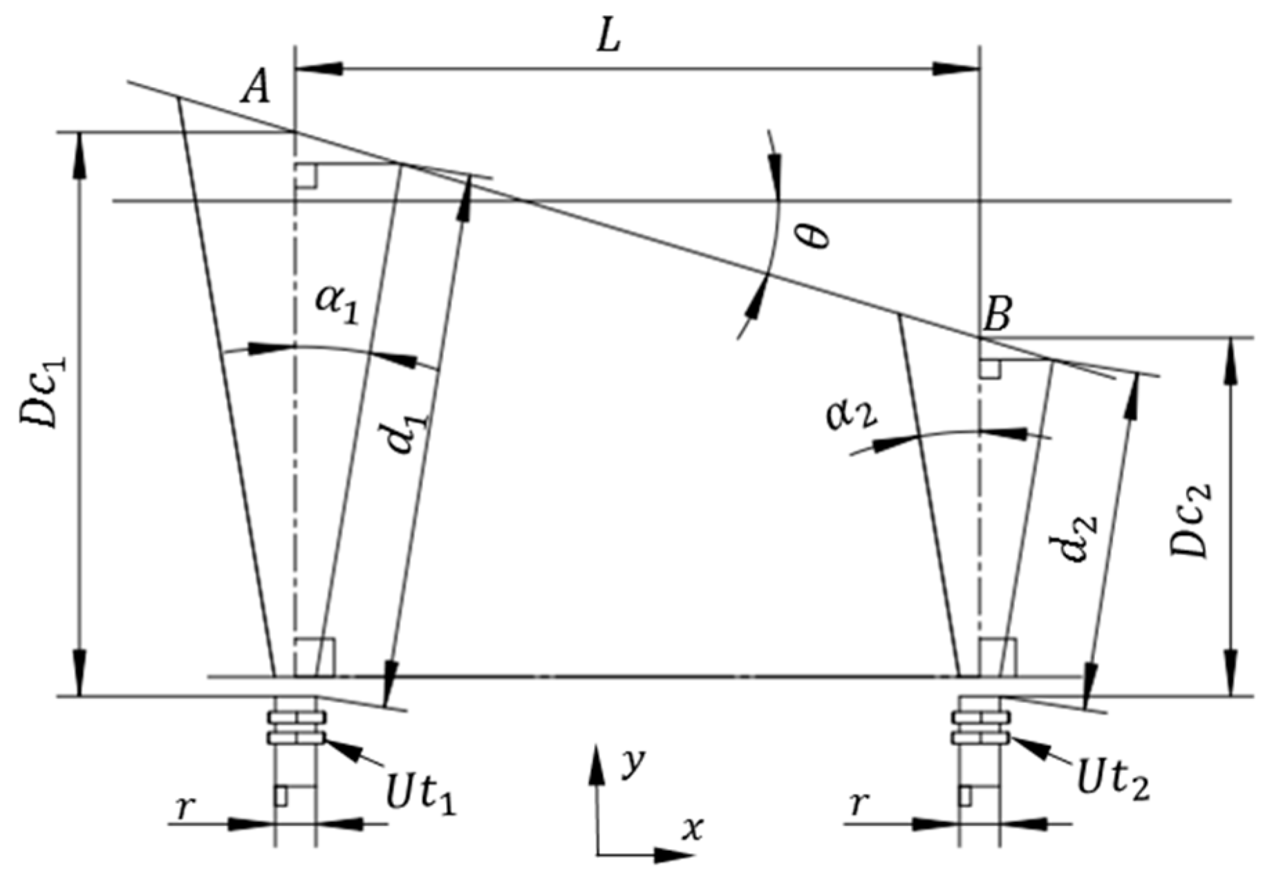
In order to analyze the impact of the divergence angle and the incident angle on the measurement accuracy of an ultrasonic sensor, a geometric model is established as shown in
Figure 1, where
represents the ultrasonic sensor,
is the number of ultrasonic sensor,
represents the divergence angle of
(in degree),
is the reference plate,
represents the direct distance measurement of
(in mm),
is the actual distance value (in mm) between
and the reference plate
AB in the
y-direction,
is the distance (in mm) between two ultrasonic sensors in the
x-direction and
is the diameter (in mm) of the ultrasonic sensor,
. The incidence angle,
, is defined as the angle between the cross-section of
and the plane of the reference plate,
AB, (in degree).
From
Figure 1, it can be concluded that the actual distance value,
, between the ultrasonic sensor,
, and the reference plate,
AB, in the
y-direction can be expressed as:
where
is the cosine trigonometric function,
,
is the sine function,
,
is the tangent function,
, and
is the number of ultrasonic sensors. Conventionally, the direct distance,
, is taken as the actual distance,
. However, from the Equation (1), it is apparent that the actual distance,
, is different from
and is influenced by the divergence angle,
, and the incidence angle,
, and that if these angles are ignored, the real distance measurement accuracy of the ultrasonic sensor would be affected. It is well known that the divergence angle,
, is an intrinsic property of a given ultrasonic sensor, which is invariant for a specified ultrasonic sensor but varies between different ultrasonic sensors, and can be obtained through experiments or from the factory manual. Usually, in most applications, the incidence angle,
, is set to zero when a single ultrasonic sensor is used or in non-positioning and non-obstacle avoidance situations. However, when multiple ultrasonic sensors are used simultaneously and accurate localization is required, such as in the application presented in
Figure 2, where two ultrasonic sensors are applied, the incidence angle,
, can be expressed as shown in Equation (2):
From Equations (1) and (2), the incidence angle,
, can be described as:
3. Edge Detection and Recognition of the Inclined Plate
Earlier in this work, the effects of the divergence angle and the incidence angle on the accuracy of the distance measurement of an ultrasonic sensor have been analyzed and a novel ranging algorithm with consideration of the divergence angle and the incidence angle of the ultrasonic sensor has been established. Now, this conclusion is going to be executed to the edge detection of an inclined plate. In order to enable object identification in a given environment, Zhong et al. [
21] determined the range, bearing angle and shape (edge or plane) of objects from a single measurement of a robot using a single transmitter and a multi-receiver of ultrasonic sensors. Ohtani and Baba [
22] designed a prototype system for the shape recognition, position and posture measurement of an object, using an ultrasonic sensor array made up of multi ultrasonic transmitters and receivers arranged in the same plane, a processing unit and a neural network. Although both of these studies could recognize objects and detect the edge of an object, the transmitter and the receiver of each ultrasonic sensor are separate, with the transmitter irradiating the measured object with ultrasonic waves and the receiver picking up the reflected waves to recognize the object. This method requires multiple positions for the transmitters and the receivers, which needs more space and is inflexible. Therefore, it is quite significant to integrate the transmitter and the receiver of an ultrasonic sensor by controlling the scanning of the ultrasonic sensor to achieve the identification of objects.
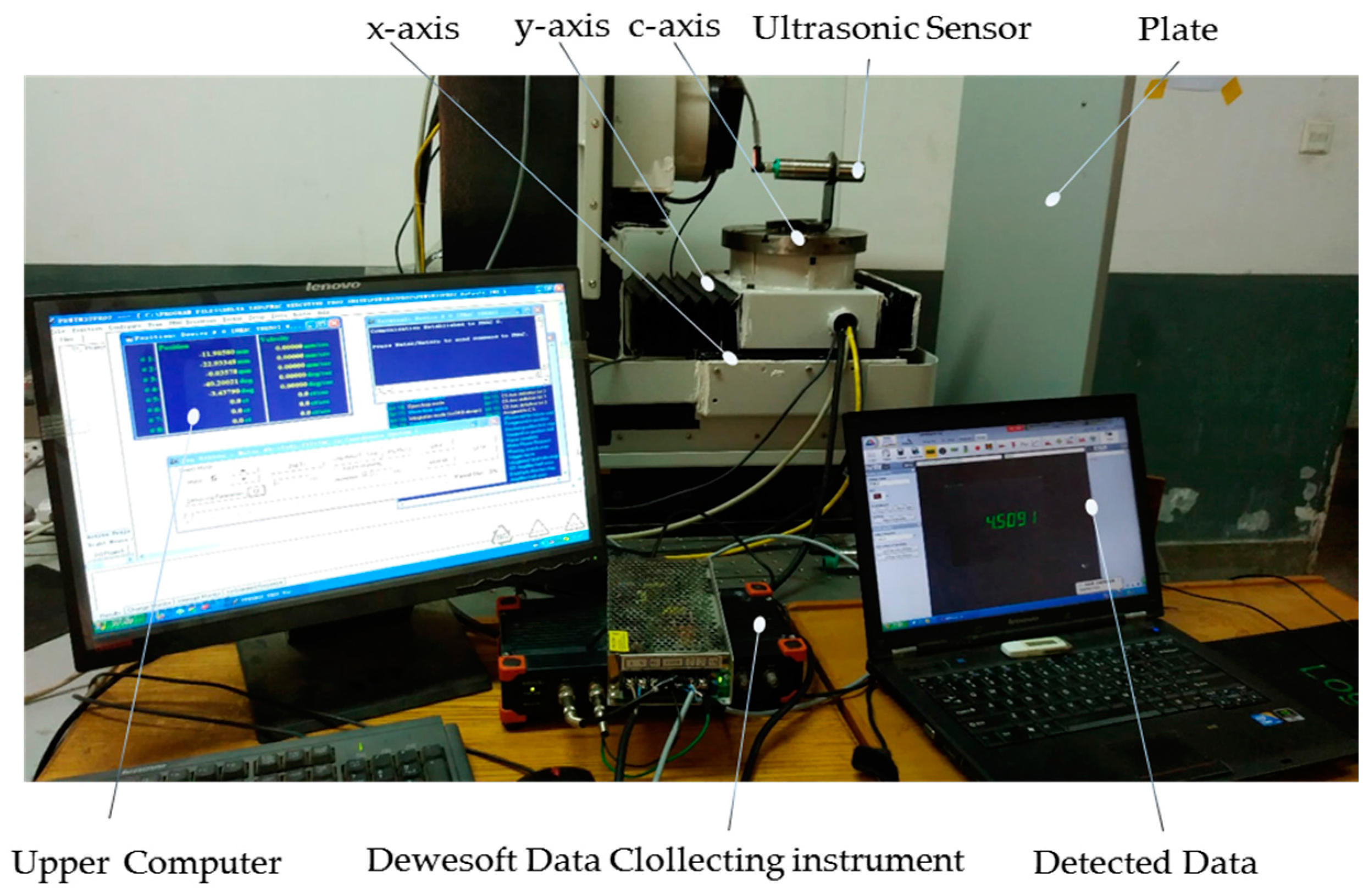
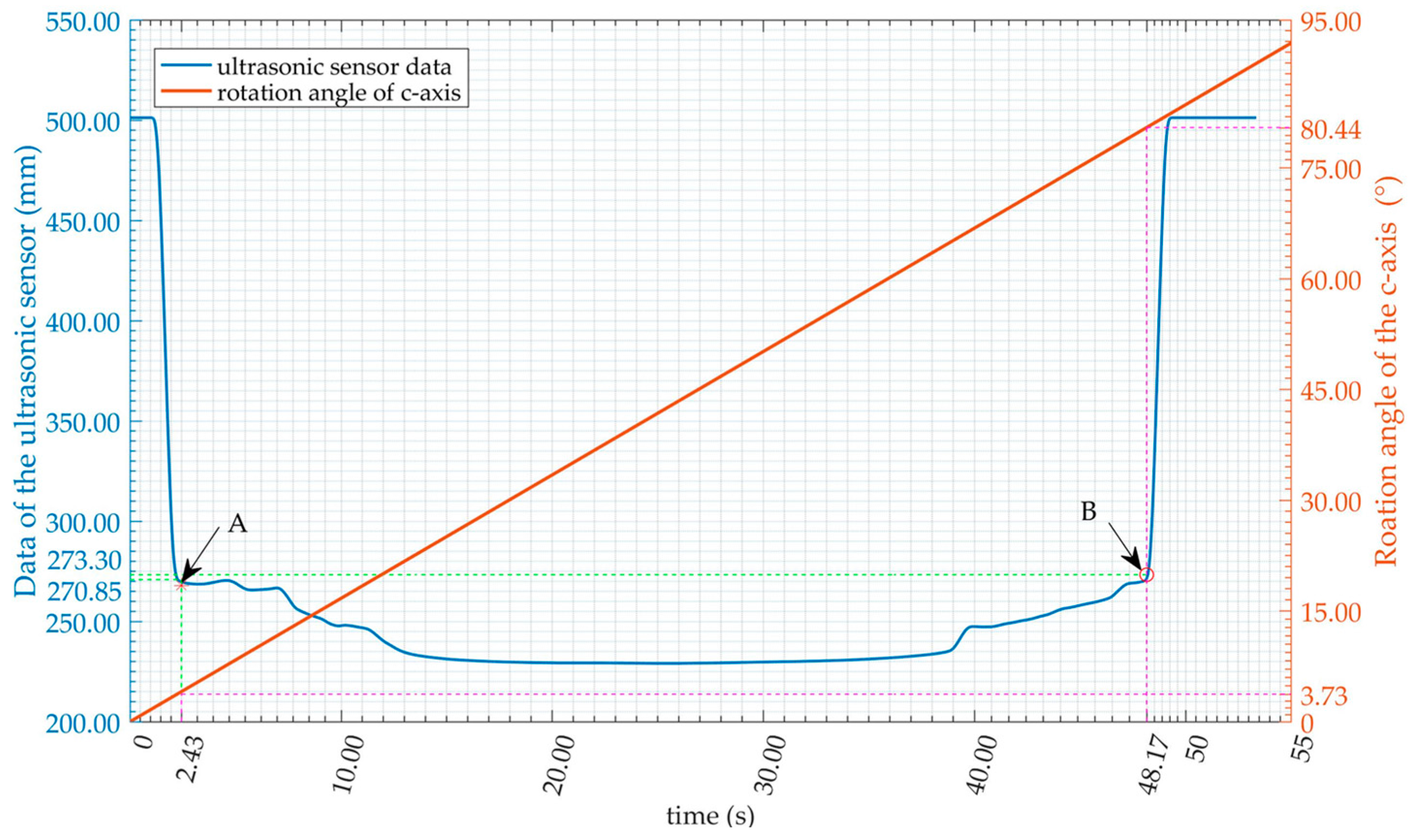
The ultrasonic sensors used in this paper are all the integrated ones, and they all have the time synchronization (avoiding the mutual interference between different ultrasonic sensors) and temperature compensation functions. The minimal detection distance of an ultrasonic sensor (dead zone) is denoted as
, and the maximal as
, the actual distance between the object and the ultrasonic sensor as
D, where
to ensure that the distance value,
D, is applicable and reliable. When the direction of the ultrasonic sensor relative to the inclined plate scans continuously, relative changes in the value measured by the ultrasonic sensor occur, whereas, at the edge of the inclined plate, the measured value oscillates irregularly. Thus, we define a threshold
to determine whether the edge of the inclined plate is detected or not, where
is a small positive real number. Let
and
be the two successive measurement record values of a specific edge, with
, where
is the total number of record groups. If
satisfies Equation (4), it is definitely accounted for that the edge of the inclined plate is detected and the distance from the ultrasonic sensor to the edge of inclined plate is
:
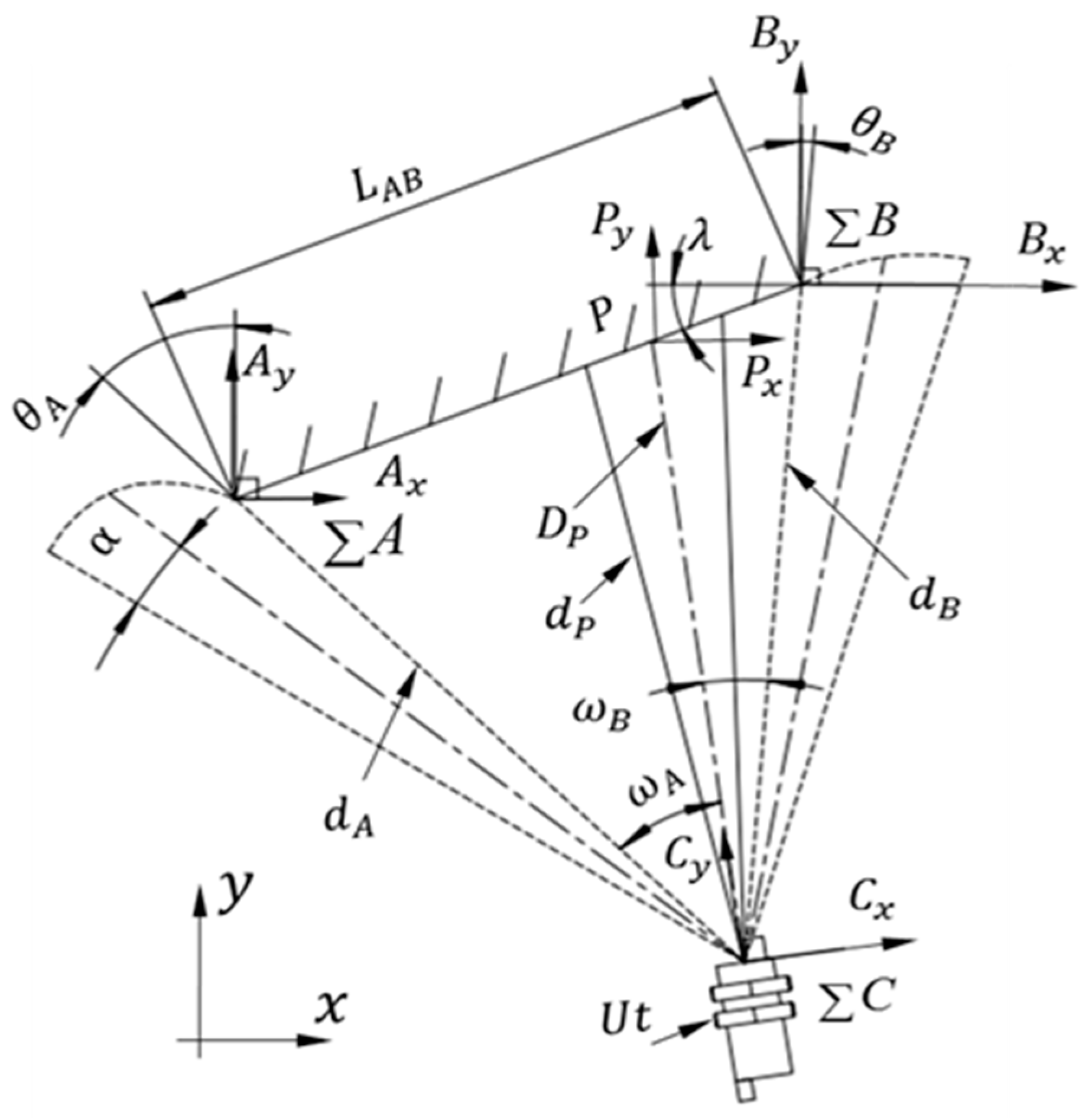
The edge detection model is as shown in
Figure 3, where
is the divergence angle of the ultrasonic sensor
,
is the coordinate system of
,
is the actual length of the inclined plate
, and
and
are the coordinate systems at point
and
, respectively.
is the angle between the inclined plate
and the horizontal direction of the
x-axis,
is the actual distance from the ultrasonic sensor,
, to the point,
, on the inclined plate. Correspondingly,
is the direct distance measurement of point
,
and
are the directly measured values of points
A and
B, respectively, while scanning the plate
AB, and can all be confirmed from Equation (4).
and
are the rotation angles of the ultrasonic sensor scanning from point
P to point
A counterclockwise and scanning from point
P to point
B clockwise, respectively, where
. The theoretical length of plate
AB,
, is obtained from
,
and
, which are contained in the triangle ∆ABC:
In Equation (6),
is a positive number, given as the length recognition threshold of the inclined plate. The values,
,
,
and
, acquired from Equation (4), are considered to be correct if
satisfies Equation (6). Otherwise, scanning is repeated until Equation (6) is satisfied and the plate is recognized. Set
as the angle between the straight line
AC and the
y-direction of the reference frame
,
as the angle between the straight line
PC and the
y-direction of the reference frame
,
as the angle between the straight line
BC and the
y-direction of the reference frame
. According to the homogeneous coordinate transformation methodology, the position and posture,
and
, of system
relative to
and
, respectively, are obtained as:
where
is a
unit matrix, and
is a rotation matrix as shown in Equation (10). The angles,
and
, in Equations (7) and (8) are as shown in Equation (9):
According to the earlier definition, the incidence angles between the ultrasonic sensor,
, and the inclined plate,
AB, at point
P can be described as
and
, respectively, relative to the reference frames
and
:
Through a review of the above studies, the position (as shown in Equation (7) or (8)) and posture (as shown in Equation (11)) of an ultrasonic sensor relative to a fixed plate can be obtained. Similarly, if the ultrasonic sensor is installed on a mobile robot, the scanning of the ultrasonic sensor is accomplished by the rotation of the robot. Thus, the position and posture of the mobile robot can also be acquired.
4. Omni-Directional Scanning Localization Method
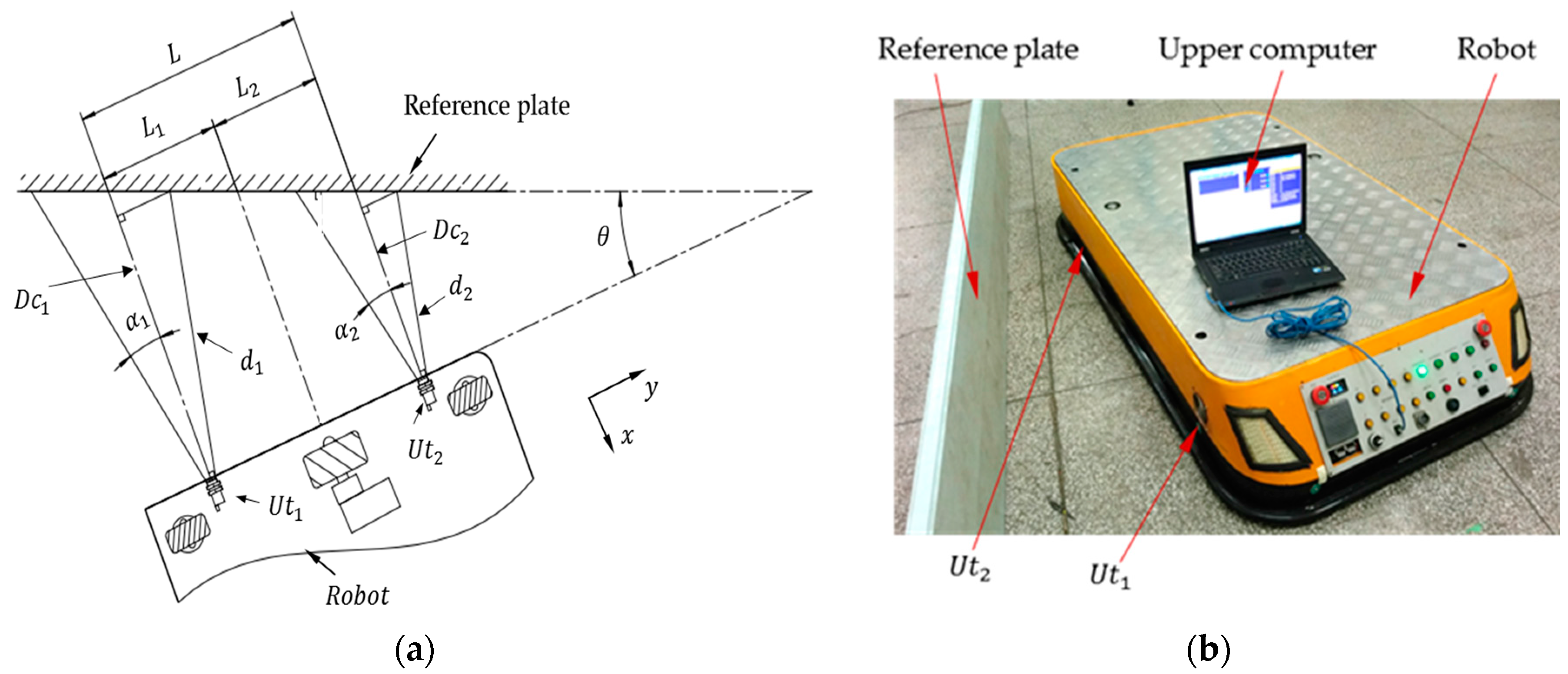
The above section introduced the ultrasonic sensor scanning recognition method of a fixed inclined plate and deduced the position and posture of the ultrasonic sensor relative to the plate. However, in most practical applications, the ultrasonic sensor is installed on a mobile robot, the rotation center of the sensor is the center of the robot and the ultrasonic sensor scans the objects along with the spin of the robot. To further research the localization method of a mobile robot with an ultrasonic sensor, a model is established as shown in
Figure 4.
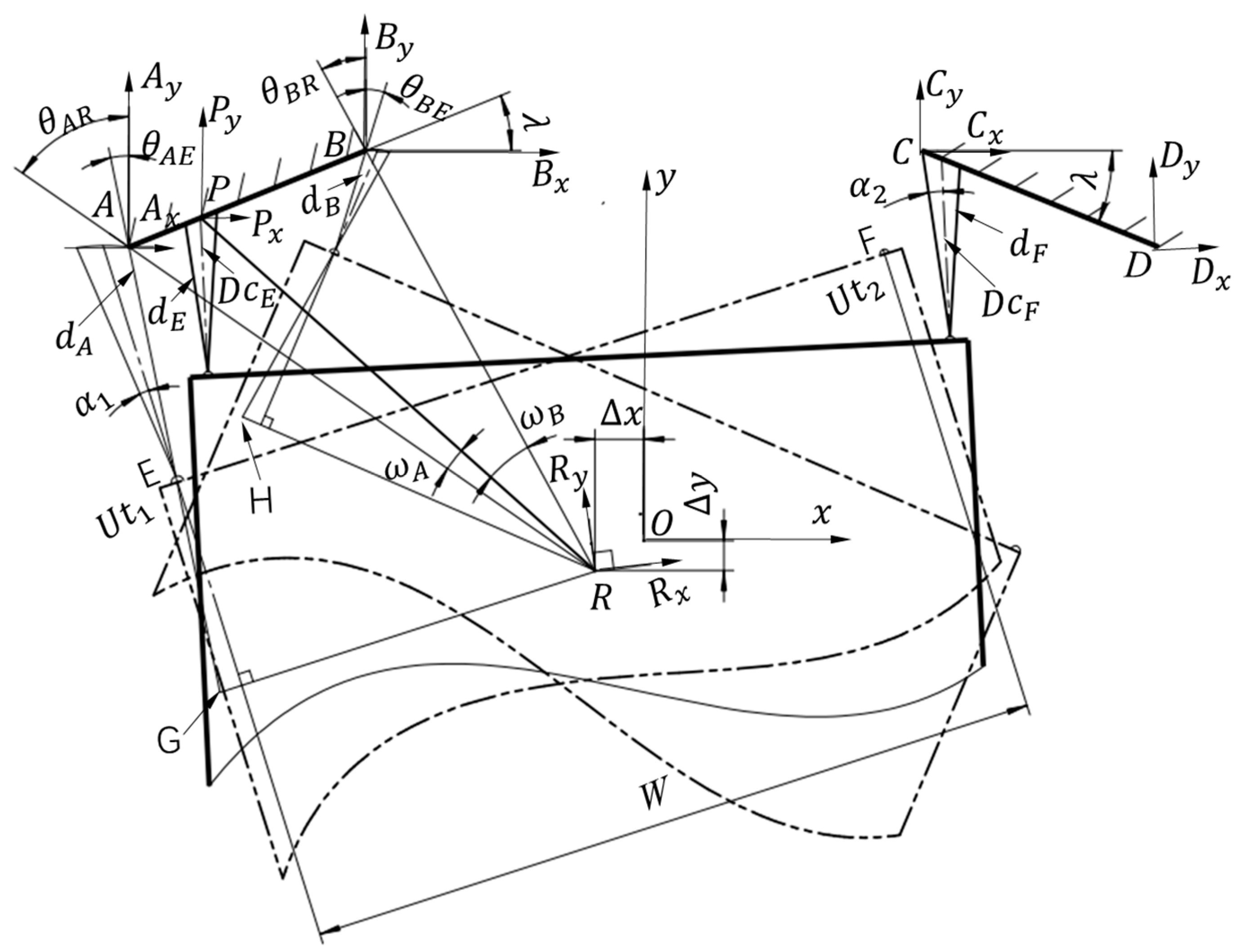
In
Figure 4, a coordinate system parallel to the reference frame
at points
A,
B,
C,
D and
P as
,
,
,
and
is established, as is the robot base reference frame,
, at the center of mobile robot, whose axes are parallel to the outlines of the robot.
AB and
CD are the two inclined plates fixed on the localization worksite or the pallet to be carried away by the robot, the angle between plate
AB and the horizontal direction of the
x-axis is
, and the angle between plate
CD and the horizontal direction of the
x-axis is
.
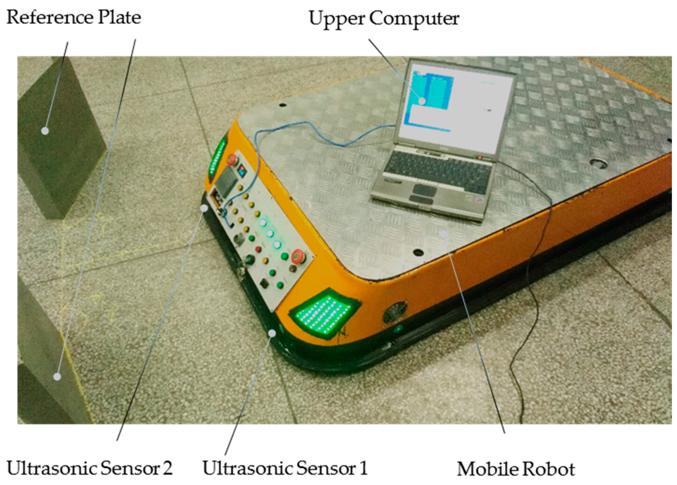
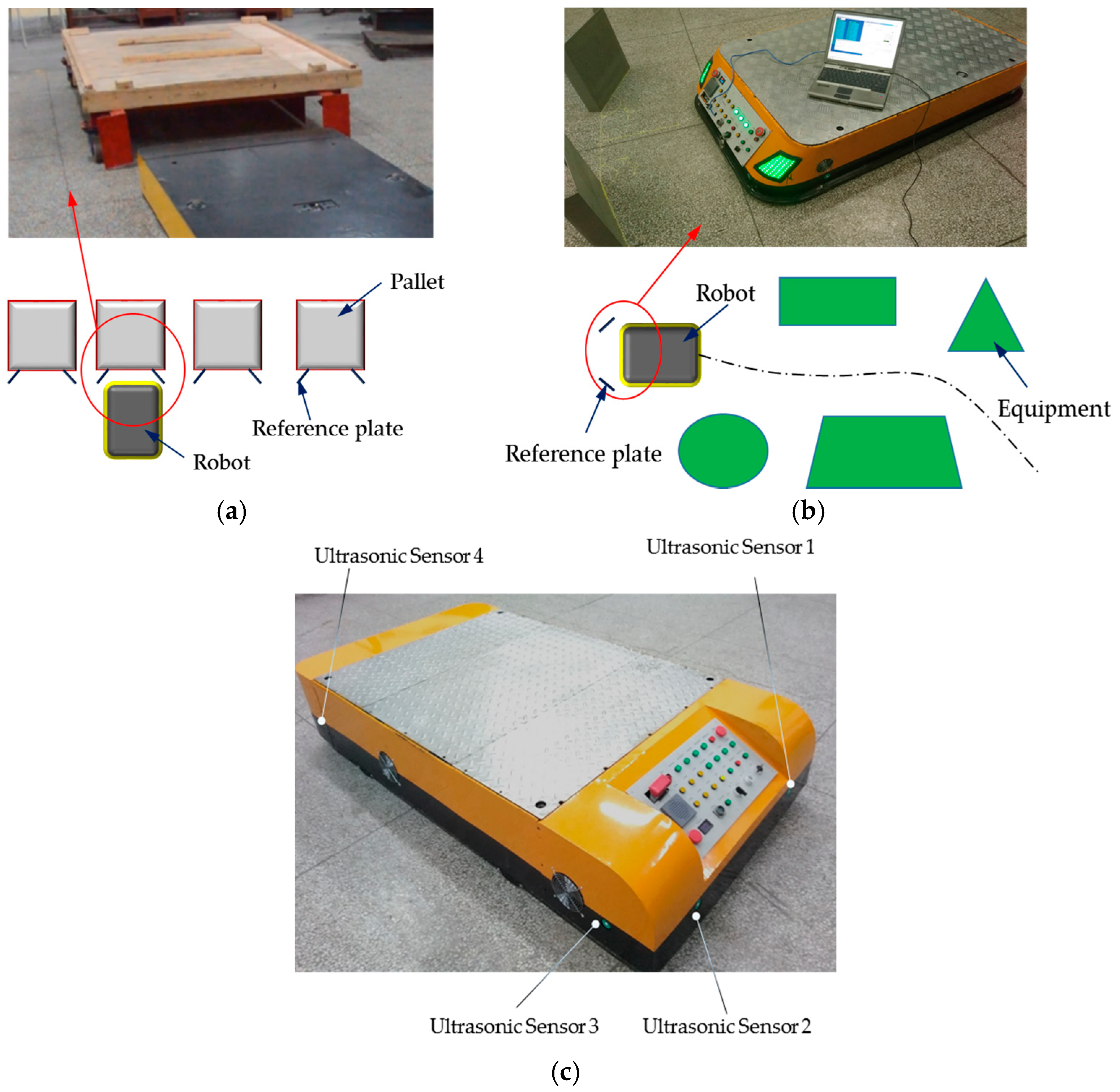
R is the center of the mobile robot body. The two ultrasonic sensors,
and
, are installed at the two points,
E and
F, on the front of the robot body, characterized by the divergence angles,
and
, respectively. The distance parallel to the transverse of the robot between
and
is
W.
is the directly measured value of
when the robot is located at position
R, and
is the actual one. Similarly,
is the directional measurement of
and
is the actual one.
P is the reflection point at the present position and posture of
.
The desired distance between the ultrasonic sensors, and , and the plate, AB and CD, is denoted as D and the posture of the robot is when the robot is at the reference position O. The inclined plate AB and CD are symmetrically arranged to the y-axis of the frame . The position and posture error of the robot at the point R relative to the reference frame, , is given as The position of point E in the frame , , is . The distance from point A to point D is at the horizontal direction of the x-axis, and the distance from point B to point C is at the horizontal direction of the x-axis.
First, the robot is controlled to point
O manually and it is made sure that
. Then, the robot rotation is controlled around its center, and, using the scanning recognition method introduced in
Section 3, the counterclockwise and clockwise angles of the robot from point
P to point
A and point
B,
and
, respectively, are recorded. Finally, the homogeneous coordinate transformations,
and
, from the coordinate system
and
to the coordinate system
is accomplished as follows:
where
is the angle between the straight line
AO and the
y-axis of the reference frame
, and
is the angle between the straight line
BO and the
y-axis of the reference frame
. From Equations (12) and (13), the distance from point
O to point
A and point
B,
and
, are as follows:
The theoretical length
of the plate AB in the triangle ∆
ABO is calculated from the values of
,
and
:
In accordance with the definition of the incidence angle, the incidence angle,
, relative to the reference frames
and
is:
Similarly, the transformation of the robot at the position
R relative to
and
are
and
, respectively:
where
is the angle between the straight line
AR and the
y-axis of the reference frame
, and
is the angle between the straight line
BR and the
y-axis of the reference frame
:
The theoretical length of the plate
AB,
, can be deduced in the triangle ∆
ABR as:
The divergence angles,
and
, of the ultrasonic sensor are listed in the Equation (25):
The position and posture error of the robot at the position
R relative to the position O in reference to
and
are
and
:
Considering Equations (12)–(15), (19), (20), (26) and (27), the errors
and
are calculated as follows:
The position and posture error thresholds of the robot at position
R are set to
. The robot meets the localization requirement if the error
satisfies the Equation (30):
Up until this stage, the position and posture and the error of the mobile robot relative to the reference frame,
and
, at the points
A and
B have been acquired. For the actual application, the localization of the robot is achieved according to the follow steps.
- Step 1
Preparation. First, the positions of the inclined plate AB and CD are set up, and their lengths and poses are specified. Then, values of thresholds , and are assigned. Next, the distance measured value D of ultrasonic sensor at the reference pose O is verified, and the transform position and posture and are calculated.
- Step 2
Satisfaction of pre-localization condition. The robot moves from somewhere to the control point R, which can be anywhere, and whether the actual distance measurement values and satisfy and , with and being positive and real numbers, are judged. If these prerequisites are met, the directly measured distances and of the ultrasonic sensor , and the rotation angles and of the robot are recorded and it is possible to proceed to Step 3. Otherwise, the process must be repeated until the pre-localization conditions are met.
- Step 3
Edge detection of inclined plate. Along with the spin of the robot around its center, the ultrasonic sensor scans the inclined plate AB, and the distance and of the edge of plate AB is measured. If and satisfy the Equation (4), it is possible go to the subsequent step. If not, re-scanning is necessary.
- Step 4
Verification of the length of the inclined plate. The theoretical length of plate AB is calculated through Equation (24). If Equation (6) is satisfied, proceed to Step 5. If not, it is necessary to return to Step 2 and repeat Steps 2–4.
- Step 5
Calculation of the position and posture of the robot. The position and posture, and , of the mobile robot relative to the reference frame and are calculated, respectively, through Equations (19) and (20).
- Step 6
Satisfaction of localization requirement. The position and posture errors, and , of the robot are computed. If and satisfy Equation (30), the localization requirement is achieved. Otherwise, return to Step 2 and repeat Steps 2–6.
6. Conclusions
First, the novel ranging algorithm of an ultrasonic sensor is established by simultaneously considering both the divergence angle and the incidence angle, which improved the accuracy of the measurement of the ultrasonic sensor.
Second, the edge detection and recognition of an inclined plate is introduced by using the proposed ranging algorithm, based on which the position and posture of an ultrasonic sensor relative to the plate are obtained.
Third, the ultrasonic sensor is installed on a mobile robot, and the positioning method of the ultrasonic sensor is extended to the omni-directional scanning localization of a mobile robot to achieve the forward, lateral and posture localizations synchronously. Details of the localization methodology are introduced and discussed, and the application steps are summarized.
Finally, the thresholds of the localization method are confirmed through experiments and experience, and the omni-directional scanning localization method is verified by the localization experiment of a differential driving robot. The application of the method on other types of mobile robots is discussed and several real applications are given.
Finally, the main concern of the proposed localization method is the local localization of a mobile robot at the worksite. Further research and application of this technology is still ongoing, such as the combination of the local and the global localization of a robot, and the research of applications of the proposed localization method for multi-robots with multi-sensor information fusion technology in dynamic circumstances.


