
A Multi-Robot Sense-Act Approach to Lead to a Proper Acting in Environmental Incidents

 , , and
Abstract
:1. Introduction
2. Materials and Methods
2.1. Multi-Robot Sense-Act System
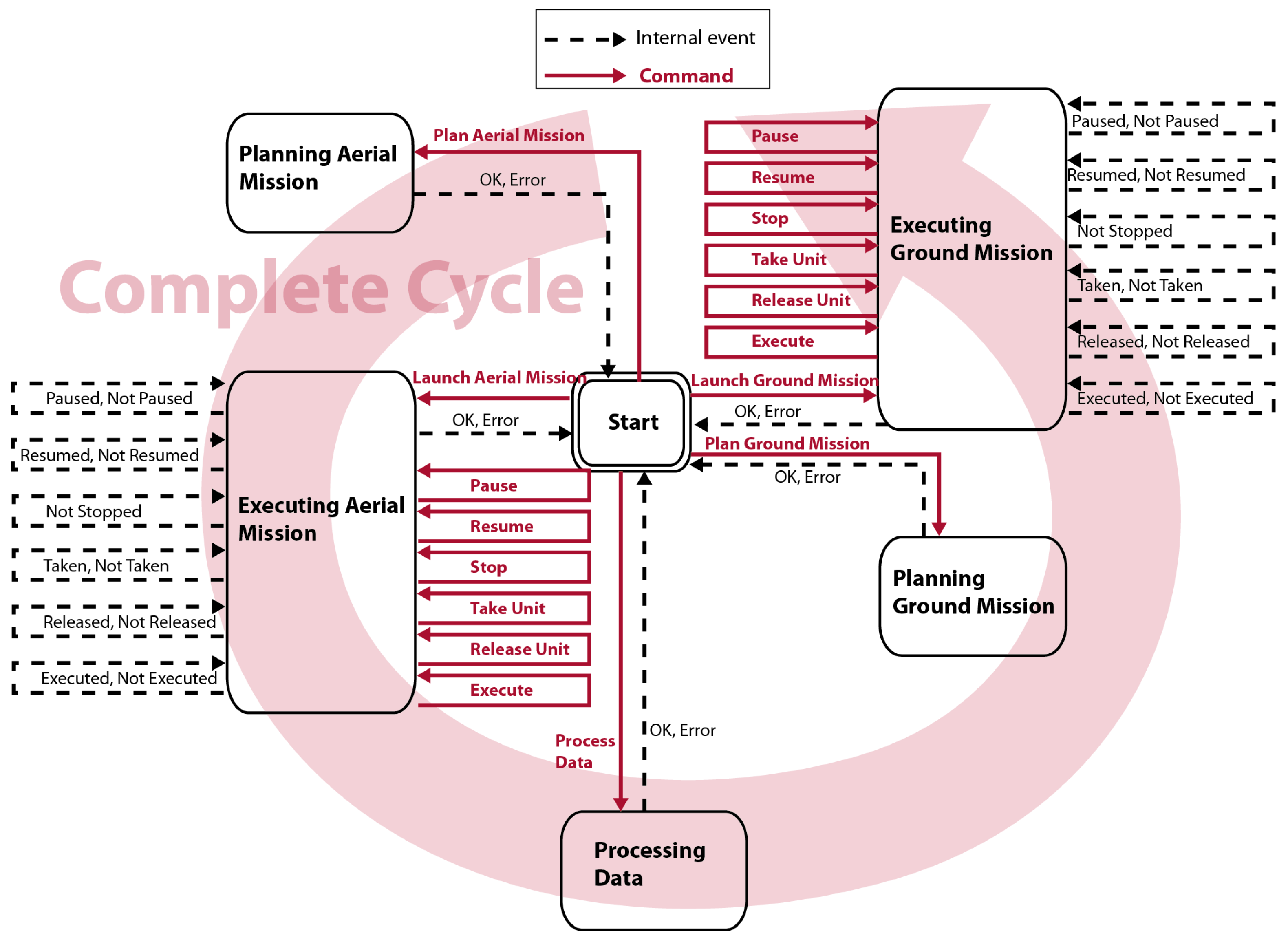
2.2. Mission Manager
- Aerial and a ground mission planners. They generate plans for units accomplishing the missions. Several planners are required for properly addressing the inherent differences of the aerial and ground units, as well as the different characteristics of inspection and intervention missions. For example, the ground units are usually limited by their turning radius, which constrain their trajectories, whereas the aerial trajectories may be limited by the battery capacity. The planners also have to take into account the features of the sensors onboard if they affect the trajectories. For example, if the aerial mission consists in taking pictures, the resolution and the size of the images of the camera must be considered in order to produce trajectories that allow capturing adequate pictures. Finally, the planners also have to consider aspects such as the fuel consumption, obstacles, distances, and unit speeds to guarantee safe and optimal trajectories.
- Aerial and ground mission controllers. They automate the mission at the fleet level. They provide an interface to communicate to all the vehicles as a coordinated fleet. They allow the vehicles in the fleet to execute simultaneously and cooperatively operations such as, launch, pause, resume, and stop. Moreover, controllers are dedicated to the decoding and transmission of the calculated plans that have to reach the units as an ordered set of commands supported by them. Additionally, the controllers must provide a stable channel to continuously receive the sensors information from the units. This information is critical to always keep the mission under control.
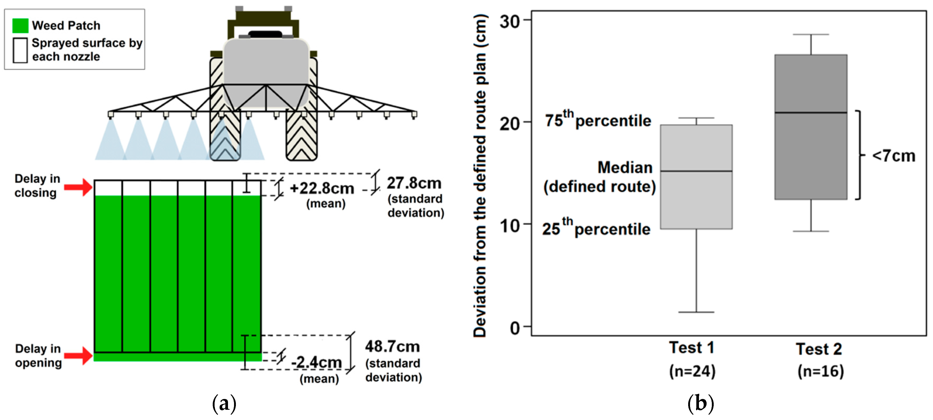
- Aerial and ground mission supervisors. They are in charge of monitoring and verifying that a mission is executed according to the plan. The mobile units’ environment is usually subject to unpredictable conditions such as wind, light changes, terrain roughness, and animals that may provoke small deviations from the scheduled plan. They receive the relevant unit’s information to analyze from the controllers. Once deviations are detected, supervisor systems should, at least, send a notification (alarm or warning) to the operator in charge of the fleet. The deviations are detected by comparing the current state of the units (position, speed, etc.) provided by the on-board sensors (e.g., GPS, IMU) and the previously calculated plans. If a difference large enough is detected, then an alarm will be generated to report the problem. The difference must be larger than some predefined thresholds to report real significant problems and to avoid noise and false positives. For example, the threshold margins employed on the results section to assume anomalies on trajectories and speeds were respectively 30 cm and 1 km/h. They help the human operator in charge of the mission to not miss any important detail.
- A processing data system, which receives and analyzes the data acquired in the inspection/scouting mission with the aim of extracting useful knowledge to the actuation/intervention mission. For instance, this module may consist of a mapping system to process images taken by the aerial units, detecting and obtaining the exact coordinates of the target points to be used for generating the plans for ground units.
- A dispatcher, which manages the entire workflow at the Mission Manager, integrating scouting, and intervention tasks. The dispatcher connects all the modules into the Mission Manager, redirecting processes to appropriate modules when it is required. Moreover, it manages external commands (plans, executions, pauses, resumes, and aborts) when the operator wants to directly control the workflow at the Mission Manager. The dispatcher allows the connection of new modules so that Mission Manager gets new functionalities.
- GUI (Graphical User Interface), which displays data generated by the Mission Manager such as plans, execution states, alarms, etc., guiding the operator through the different workflow steps. This module allows the operator to directly control to the Mission Manager modules and consequently gathers the human-system interaction. The main actions allowed are planning an aerial/ground mission, launching an aerial/ground mission, and processing the data acquired by the missions.
- Portable GUI, which allows operator to individually control the units outside the Base Station, i.e., at field. The portable GUI is actually useful in a breakdown case.
- Database, where all data such as plans, commands, or telemetry of the mission are stored. They are required to interrupt and resume the process, or even to perform offline processes when the units are not working, for example, the case of image processing or any other big data activity that could turn out to be important in the management of future incidents.
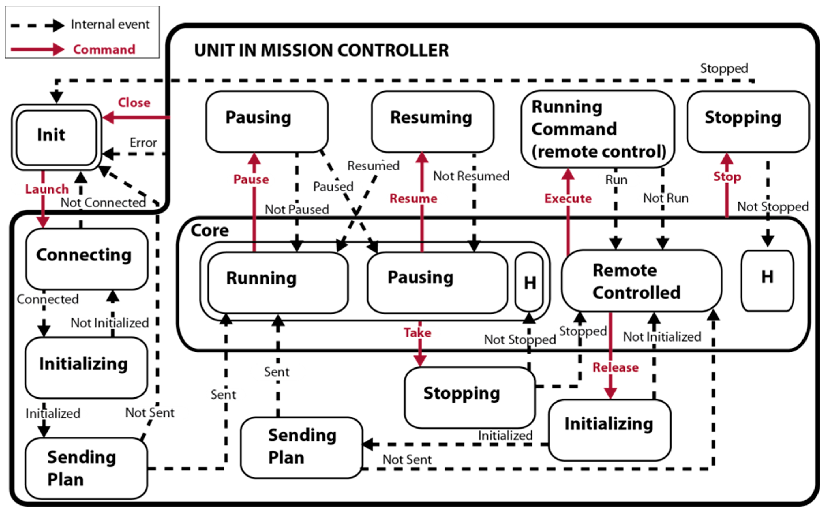
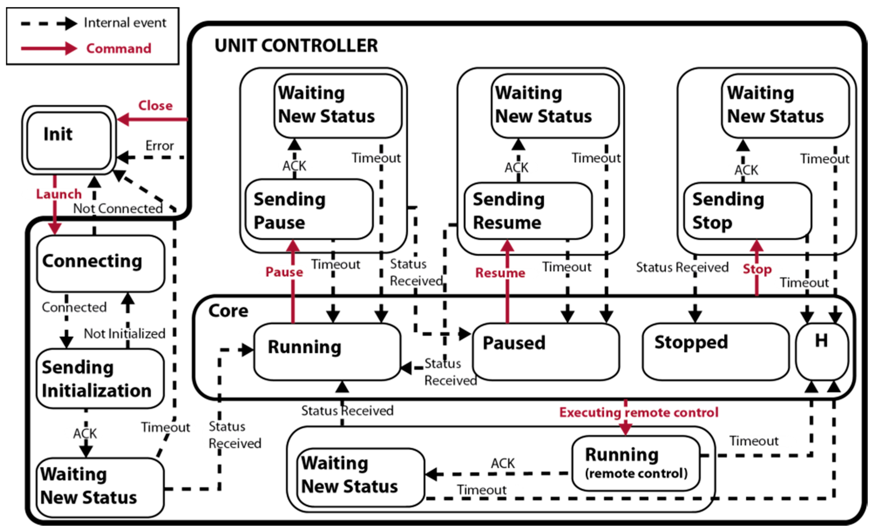
2.2.1. The Mission Controllers
- Launch a mission: The controller establishes with all the units and sends the corresponding sub-plan to each one using the actuation commands shown in Table 2. When a unit starts executing the assigned sub-plan, the controller emits the launched signal and changes its state to running state. If no unit starts, the controller emits the signal not launched and returns to the initial state.
- Pause a mission: The controller send a pause command to all units and change its state to paused state after checking that all vehicles have fulfilled the order. Otherwise, the controller outputs the signal not paused and remains in the running state.
- Resume a mission: The controller commands to continue the execution paused to every unit. The controller returns to the running state when at least one unit resumes the execution.
- Stop a mission: The controller sends a stop command to all units. When all units perform this command, the mission ends, the connections are closed, and the controller returns to the initial state.
- Close connections: This command closes all open connections when the units are already stopped.
- Take control of a unit (for remote operation): This command lets the operator to take the control of a unit of the fleet that is involved in the mission. The controller stores the remaining sub-plan before stopping the unit. The unit is no longer considered part of the fleet.
- Release a unit: It returns the unit to the fleet. The unit resumes the sub-plan stored by the controller when the unit was taken for remote operation.
- Run Command (for remote operation): It allows an operator to directly send commands (displacement, device setting, etc.) to a unit that is no longer part of the fleet and, therefore, is not involved in the mission.
2.2.2. The Dispatcher
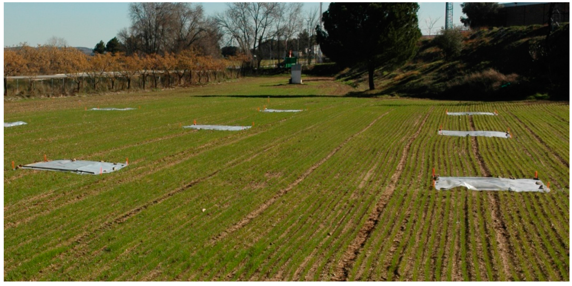
3. The Multi-Robot Sense-Act System to Perform a Site-Specific Weed Treatment
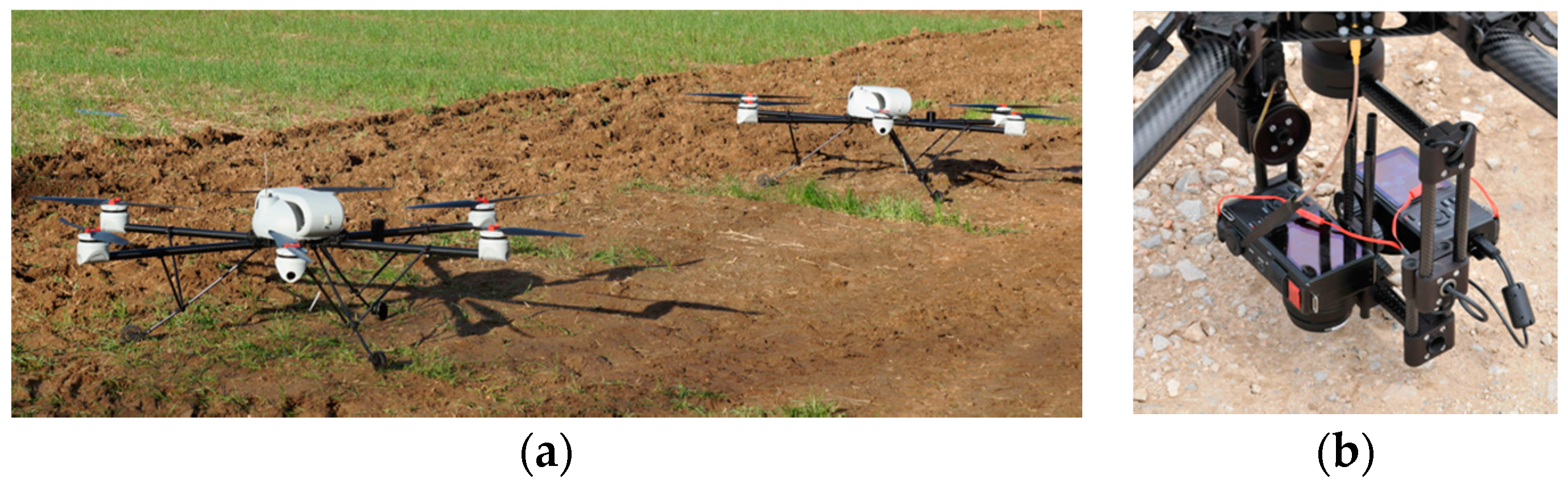
3.1. Aerial Fleet
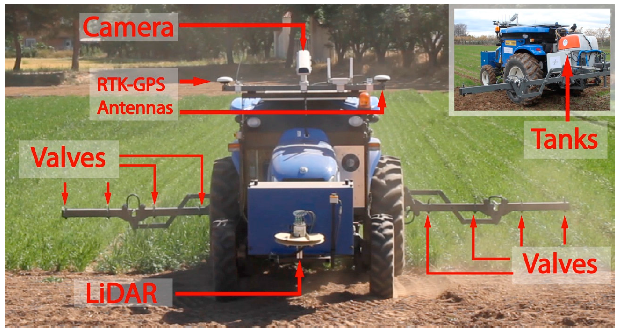
3.2. Ground Fleet
3.3. Mission Manager Implementation
3.4. Base Station and Network
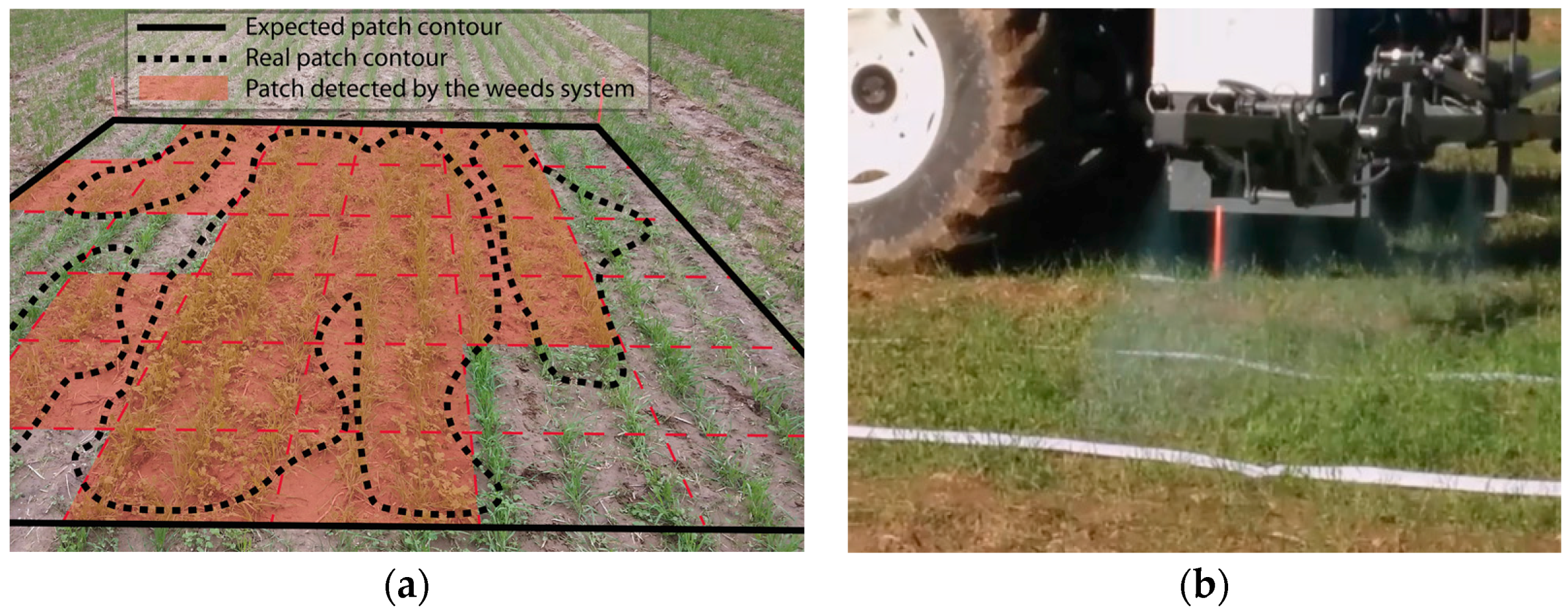
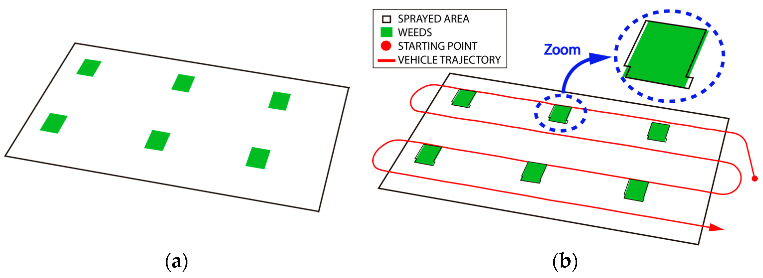
4. Results and Discussion
5. Conclusions and Future Work
Acknowledgments
Author Contributions
Conflicts of Interest
References
- Gaudin, S. MIT Builds SWimming, Oil-Eating Robots. 2010. Available online: http://www.computerworld.com/article/2514966/emerging-technology/mit-builds-swimming--oil-eating-robots.html (accessed on 7 July 2016).
- Lindemuth, M.; Murphy, R.; Steimle, E.; Armitage, W.; Dreger, K.; Elliot, T.; Hall, M.; Kramer, J.; Palankar, M.; Pratt, K.; et al. Sea robot-assisted inspection. IEEE Robot. Autom. Mag. 2011, 18, 96–107. [Google Scholar] [CrossRef]
- Casbeer, D.W.; Beard, R.W.; McLain, T.W.; Li, S.M.; Mehra, R.K. Forest fire monitoring with multiple small UAVs. In Proceedings of the American Control Conference, Portland, OR, USA, 8–10 June 2005.
- Viguria, A.; Maza, I.; Ollero, A. Distributed Service-Based Cooperation in Aerial/Ground Robot Teams Applied to Fire Detection and Extinguishing Missions. Adv. Robot. 2012, 24, 1–23. [Google Scholar] [CrossRef]
- Michael, N.; Shen, S.; Mohta, K.; Mulgaonkar, Y.; Kumar, V.; Nagatani, K.; Okada, Y.; Kiribayashi, S.; Otake, K.; Yoshida, K.; et al. Collaborative mapping of an earthquake-damaged building via ground and aerial robots. J. Field Robot. 2012, 29, 832–841. [Google Scholar] [CrossRef]
- Grocholsky, B.; Keller, J.; Kumar, V.; Pappas, G. Cooperative air and ground surveillance. IEEE Robot. Autom. Mag. 2006, 13, 16–25. [Google Scholar] [CrossRef]
- Harik, E.H.C.; Guinand, F.; Pelvillain, H.; Guerin, F.; Brethe, J.F. A decentralized interactive architecture for aerial and ground mobile robots cooperation. In Proceedings of the International Conference on Control, Automation and Robotics (ICCAR), Copenhagen, Denmark, 11–12 June 2015.
- Martínez-de Dios, J.; Merino, L.; Caballero, A.; Ollero, A. Automatic Forest-Fire Measuring Using Ground Stations and Unmanned Aerial Systems. Sensors 2011, 11, 6328–6353. [Google Scholar] [CrossRef] [PubMed]
- Hsieh, M.A.; Cowley, A.; Keller, J.F.; Chaimowicz, L.; Grocholsky, B.; Kumar, V.; Taylor, C.; Endo, Y.; Arkin, R.; Jung, B.; et al. Adaptive teams of autonomous aerial and ground robots for situational awareness. J. Field Robot. 2007, 24, 991–1014. [Google Scholar] [CrossRef]
- Tanner, H.G.; Christodoulakis, D.K. Decentralized cooperative control of heterogeneous vehicle groups. Robot. Auton. Syst. 2007, 55, 811–823. [Google Scholar] [CrossRef]
- Shkurti, F.; Xu, A.; Meghjani, M.; Higuera, J.C.G.; Girdhar, Y.; Giguere, P.; Dey, B.B.; Li, J.; Kalmbach, A.; Prahacs, C.; et al. Multi-domain monitoring of marine environments using a heterogeneous robot team. In Proceedings of the IEEE/RSJ International Conference on Intelligent Robots and Systems, Vilamoura, Portugal, 7–12 October 2012; pp. 1747–1753.
- Langerwisch, M.; Wittmann, T.; Thamke, S.; Remmersmann, T.; Tiderko, A.; Wagner, B. Heterogeneous teams of unmanned ground and aerial robots for reconnaissance and surveillance—A field experiment. In Proceedings of the IEEE International Symposium on Safety, Security, and Rescue Robotics (SSRR), Linkoping, Sweden, 21–26 October 2013.
- Fernandez-Quintanilla, C.; Dorado, J.; San Martin, C.; Conesa-Muñoz, J.; Ribeiro, A. A five-step guide for planning a robotic site-specific weed management program for winter wheat. In Proceedings of the 1st International Workshop on Robotics and Associated High-Technologies and Equipment for Agriculture, Pisa, Italy, 19–21 September 2011; pp. 3–11.
- Pierce, F.J.; Nowak, P. Aspects of Precision Agriculture. Adv. Agron. 1999, 67, 1–85. [Google Scholar]
- Marshall, E.J. Field-scale estimates of grass weed populations in arable land. Weed Res. 1988, 28, 191–198. [Google Scholar] [CrossRef]
- Johnson, G.A.; Mortensen, D.A.; Martin, A.R. A simulation of herbicide use based on weed spatial distribution. Weed Res. 1995, 35, 197–205. [Google Scholar] [CrossRef]
- Pimentel, D.; Acquay, H.; Biltonen, M.; Rice, P.; Silva, M.; Nelson, J.; Lipner, V.; Giodano, S.; Horowitz, A.; D’Amore, M. Environmental and economic costs of pesticide use. BioScience 1992, 42, 750–758. [Google Scholar] [CrossRef]
- European Crop Protection Association (ECPA). Report Annual Review 2011. 2012. Available online: http://www.ecpa.eu/files/attachments/Annual Report_web.pdf (accessed on 25 June 2016).
- Miller, G.T. Sustaining the Earth: An Integrated Approach; Brooks/Cole: Boston, MA, USA, 2004. [Google Scholar]
- European Crop Protection Association (ECPA). Report Annual Review 2007. 2008. Available online: http://www.ecpa.be/files/ecpa/documentslive/22/18192_ECPA%202008%20Annual%20report.pdf (accessed on 18 May 2016).
- Conesa-Muñoz, J.; Bengochea-Guevara, J.M.; Andujar, D.; Ribeiro, A. Route planning for agricultural tasks: A general approach for fleets of autonomous vehicles in site-specific herbicide applications. Comput. Electron. Agric. 2016, 127, 204–220. [Google Scholar] [CrossRef]
- Parrot. AR Drone 2.0. 2016. Available online: http://www.parrot.com/de/produkte/ardrone-2/ (accessed on 24 May 2016).
- Mota. Mota Commercial Drones. 2016. Available online: https://www.mota.com/drone/ (accessed on 18 March 2016).
- Robotnik. Mobile Robotnik Models. 2016. Available online: http://www.robotnik.eu/mobile-robots/ (accessed on 28 June 2016).
- Clearpath Robotics. 2016. Available online: http://www.clearpathrobotics.com/ (accessed on 24 May 2016).
- Blackmore, S.; Stout, B.; Wang, M.; Runov, B. Robotic—The future of agricultural mechanisation? In Proceedings of the 5th European Conference on Precision Agriculture, Uppsala, Sweden, 9–12 June 2005; pp. 621–628.
- Harel, D.; Pnueli, A. On the Development of Reactive Systems; Springer: Berlin, Germany; Heidelberg, Germany, 1985. [Google Scholar]
- Harel, D. Statecharts: A visual formalism for complex systems. Sci. Comput. Progr. 1987, 8, 231–274. [Google Scholar] [CrossRef]
- RHEA Website. RHEA Project Description. 2010–2014. Available online: http://www.rhea-project.eu/ (accessed on 31 May 2016).
- AirRobot Website. AirRobot Company Description. 2015. Available online: http://www.airrobot.de/ (accessed on 31 May 2016).
- Boomer 3000 Series. Case New Holland. 2015. Available online: http://agriculture.newholland.com/us/en/Products/Compact-Tractors-and-Commercial-Mowers/Boomer-3000-Series/Pages/3050_modelversion.aspx (accessed on 31 May 2016).
- Burgos-Artizzu, X.P.; Ribeiro, A.; Guijarro, M.; Pajares, G. Real-time image processing for crop/weed discrimination in maize fields. Comput. Electron. Agric. 2011, 75, 337–346. [Google Scholar] [CrossRef] [Green Version]
- Carballido, J.; Perez-Ruiz, M.; Gliever, C.; Agüera, J. Design, development and lab evaluation of a weed control sprayer to be used in robotic systems. In Proceedings of the First International Conference on Robotic and Associated High-Technologies and Equipment for Agriculture, Pisa, Italy, 19–20 September 2012; Volume 1, pp. 23–29.
- Emmi, L.; Gonzalez-de-Soto, M.; Pajares, G.; Gonzalez-de-Santos, P. Integrating Sensory/Actuation Systems in Agricultural Vehicles. Sensors 2014, 14, 4014–4049. [Google Scholar] [CrossRef] [PubMed]
- Valente, J.; Del Cerro, J.; Barrientos, A.; Sanz, D. Aerial coverage optimization in precision agriculture management: A musical harmony inspired approach. Comput. Electron. Agric. 2013, 99, 153–159. [Google Scholar] [CrossRef]
- Del Cerro, J.; Sanz, D.; Valente, J.; Rossi, C.; Cancar, L.; Barrientos, A. Flota de vehículos aéreos para fotografía de alta resolución en aplicaciones de agricultura de precisión. In Actas de las XXXV Jornadas de Automática; Archivo Digital UPM: Valencia, Spain, 2014; pp. 265–271. [Google Scholar]
- Conesa-Muñoz, J.; Gonzalez-de-Soto, M.; Gonzalez-de-Santos, P.; Ribeiro, A. Distributed multi-level supervision to effectively monitor the operations of a fleet of autonomous vehicles in agricultural tasks. Sensors 2015, 15, 5402–5428. [Google Scholar] [CrossRef] [PubMed]
- Qt. Qt Libraries. 2016. Available online: http://www.qt.io/developers/ (accessed on 31 May 2016).
- Rabatel, G.; Labbé, S. A fully automatized processing chain for high-resolution multispectral image acquisition of crop parcels by UAV. In Proceedings of the 10th European Conference on Precision Agriculture, Tel Aviv, Israel, 12–16 July 2015; pp. 135–141.
- Torres-Sánchez, J.; López-Granados, F.; De Castro, A.I.; Peña-Barragán, J.M. Configuration and specifications of an unmanned aerial vehicle (UAV) for early site specific weed management. PLoS ONE 2013, 8. [Google Scholar] [CrossRef]
- Cyberbotics Website. Webots Software. 2016. Available online: https://www.cyberbotics.com (accessed on 31 May 2016).
- Wilkins, D.E.; Lee, T.J.; Berry, P. Interactive Execution Monitoring of Agent Teams. J. Artif. Intell. Res. 2003, 18, 217–261. [Google Scholar]
- Hinterhofer, T.; Tomic, S. Wireless QoS-enabled multi-technology communication for the RHEA robotic fleet. In Proceedings of the RHEA-2011 Robotics and Associated High-Technologies and Equipment for Agriculture, Pisa, Italy, 19–21 September 2011; pp. 173–186.
- Conesa-Muñoz, J.; Ribeiro, A. Spraying Mission Test. 2015. Available online: https://www.youtube.com/watch?v=FfDHA-Jmfrc (accessed on 31 May 2016).
- RHEA Website. RHEA January Demo. 2014. Available online: http://www.rhea-project.eu/img/Videos/DEMO_short_version_01.mp4 (accessed on 31 May 2016).
- Conesa-Muñoz, J.; Ribeiro, A. Several Tractors Mission Test. 2015. Available online: https://www.youtube.com/watch?v=XeMrMdKyGiY (accessed on 31 May 2016).


| Aspects | Large Tractors | Fleets of Small/Medium Size Robots |
|---|---|---|
| Safety in autonomous operation mode | Becomes a safety problem in case of failure | Small/medium sized robots can interact with humans in a safer way |
| Fault tolerance | A failure will stop the entire work until the machine is repaired | Robot teams allow re-planning the overall task in case of failure of one unit |
| Impact on crop/field | High soil compaction | Lower soil damage (lighter vehicles) and more precise movement |
| Human Resources | One operator for each vehicle | One operator can supervise the whole fleet |
| Operation | Description |
|---|---|
| Initialization | Set up the initial configuration of a unit |
| Actuation | Actions on the unit (displacements, speed changes, tool activations, plan executions...) |
| Pause | Interrupt the current operation, keeping the same state until receiving a resume command |
| Resume | Resume the activity that was being carrying out when received the paused command |
| Stop | Stop the unit movement and actuation |
| Disconnect | Close the connection from which the request has been made |
| Failure | Importance (in Terms of Safety) | Missions Detected (%) | Mission Failed? | System Reaction |
|---|---|---|---|---|
| Units internal errors | Very high | 15 | Yes | Report the operator and abort the mission |
| Wrong path planning | Medium | 0 | No | Report and ask for a new planning |
| Mission not loaded | Low | 15 | No | Report and ask for a new execution |
| Weeds system failed | Low | 0 | No | Report and ask for a new execution |
| Out of trajectory | High | 80 | No | Report |
| Valves delay | Low | 75 | No | Report |
| Wrong speed | Medium | 85 | No | Report |
| Collisions | Very high | 40 | No | Report and manage the traffic (pause/resume the units that are going to collide) |
© 2016 by the authors; licensee MDPI, Basel, Switzerland. This article is an open access article distributed under the terms and conditions of the Creative Commons Attribution (CC-BY) license (http://creativecommons.org/licenses/by/4.0/).
Share and Cite
Conesa-Muñoz, J.; Valente, J.; Del Cerro, J.; Barrientos, A.; Ribeiro, A. A Multi-Robot Sense-Act Approach to Lead to a Proper Acting in Environmental Incidents. Sensors 2016, 16, 1269. https://doi.org/10.3390/s16081269
Conesa-Muñoz J, Valente J, Del Cerro J, Barrientos A, Ribeiro A. A Multi-Robot Sense-Act Approach to Lead to a Proper Acting in Environmental Incidents. Sensors. 2016; 16(8):1269. https://doi.org/10.3390/s16081269
Chicago/Turabian StyleConesa-Muñoz, Jesús, João Valente, Jaime Del Cerro, Antonio Barrientos, and Angela Ribeiro. 2016. "A Multi-Robot Sense-Act Approach to Lead to a Proper Acting in Environmental Incidents" Sensors 16, no. 8: 1269. https://doi.org/10.3390/s16081269