
Reverse Engineering and Security Evaluation of Commercial Tags for RFID-Based IoT Applications


Abstract
:1. Introduction
2. Related Work
2.1. Basic Types of RFID Systems
- LF (Low Frequency) RFID. According to the ITU (International Telecommunications Union), the LF band goes between 30 kHz and 300 kHz. Frequency and power in this band are not regulated globally in the same way: most systems operate at 125 kHz, but there are some at 134 kHz. The reading range provided is short (generally up to 10 cm), so, in practice, LF devices are not usually sensitive to radio interference. Its most popular applications are access control and animal identification (mainly for pets and livestock).
- HF (High Frequency) RFID. Although the HF band goes from 3 MHz to 30 MHz, most systems operate at 13.56 MHz. HF systems can reach a reading distance of up to 1 m, what can lead to interference and, therefore, MAC (Medium-Access Control) mechanisms have to be implemented. This sort of RFID systems is massively used in transportation, payment, ticketing, and access control.
- UHF (Ultra-High Frequency) RFID. The UHF band actually covers from 300 MHz to 3 GHz, but most systems operate in the ISM (Industrial-Scientific-Medical) bands around 860–960 MHz and 2.45 GHz. UHF tag can be easily read at 10 m, so they are ideal for inventory management and item tracking in logistics.
- Passive systems. They do not need internal batteries to operate, since they rectify the energy sent through the reader’s antenna. There are LF, HF, and UHF passive systems, which nowadays can be easily read at a 10-m distance.
- Active systems. They include batteries, what allow them to reach further distances (usually up to 100 m). Due to power regulations, almost all active systems operate in the UHF band.
- Semi-active, semi-passive or BAP (Battery-Assisted Passive) systems. They decrease power consumption by using batteries just for powering the tags for certain functionality. Commonly, batteries are used to power up the basic electronics, while the energy obtained from the reader is used for powering the communications interface.
2.2. Attacks against RFID
2.2.1. Risks and Threats
- Confidentiality. It is related to the importance of protecting the most sensitive information from unauthorized access.
- Integrity. It consists in protecting data from modification or deletion by unauthorized parties, and ensuring that, when authorized people make changes, they can be undone if some damage occurs.
- Availability. It is the possibility of accessing the system data when needed.
- Security risks. They are derived from actions able to damage, block or take advantage from a service in a malicious way. The action is usually carried out with the objective of obtaining a profit or just to damage the access to certain service.
- Privacy risks. These risks affect the confidential information of the users. In some cases, when a user interacts constantly with the environment, objects, and people around, an attacker would be even able to obtain extremely accurate information on the personal data, location, behavior and habits. In the case of RFID, there are mainly two privacy risks:
- -
- Unauthorized access to personal data. Many systems store private data on RFID tags or transmit them when a tag and a reader exchange information.
- -
- Personal tracking. This is probably the most feared, since an attacker might determine routes, purchases and habits of a specific person.
2.2.2. Physical Attacks
- Reverse engineering. Most tags are not tamper-proof and can be disassembled and analyzed. A description of the most relevant reverse-engineering attacks is given later in Section 2.4.
- Signal blocking or jamming. It consists of blocking tag communications to avoid sending data to a reader.
- Tag removal. It consists of removing an RFID tag or replacing it with another one.
- Physical destruction. In this case the attacker destroys the RFID tag by applying pressure, tension loads, or high/low temperatures; by exposing the tag to certain chemicals; or by just clipping the antenna off.
- Wireless zapping. RFID zappers are able to send energy remotely that, once rectified, is so high that certain components of the tag might be burned.
2.2.3. Software Attacks
- Remote switch off. Researchers have found that it is possible to misuse the kill password in some tags (EPC Class-1 Gen-2) with a passive eavesdropper and then disable the tags [55].
- Tag cloning. In this attack, the Unique Identifier (UID) and/or the content of the RFID is extracted and inserted into another tag [56].
- Command injection. Some readers are vulnerable to remote code execution by just reading the content of a tag [57].
- SQL injection. It has been found that some reader middleware is vulnerable to the injection of random SQL commands [57].
- Virus/Malware injection. Although difficult to perform in the vast majority of RFID tags due to their low storage capacity, it is possible in certain tags to insert malicious code that is able to be transmitted to other tags [57].
- Network protocol attacks. Many systems integrate back-end databases and connect to networking devices, which are susceptible to the same vulnerabilities as any other general purpose networking device.
2.2.4. Channel Attacks
- Denial of Service (DoS) attacks. The channel is flooded with such a large amount of information that the reader cannot deal with the signals sent by real tags [60].
- Signal replaying. It consists in recording the RFID signal in certain time instants with the objective of replaying it later.
2.3. Countermeasures Against the Most Common Attacks
- Reader-Tag authentication. Both devices should carry out a two-way authentication, so only legitimate devices can communicate. This mechanism prevents certain types of remote tag destruction (i.e., only an authorized user can send a kill command), unauthorized readings, and MitM attacks. For instance, a lightweight authentication protocol is presented in [63].
- Rogue device detection. If a reader is provided with the capacity of detecting abnormal tag behaviors, it might avoid DoS attacks, certain unauthorized readings, command/virus/malware injection, and network protocol attacks.
- Use of cryptography. Due to the limited power and performance of most RFID tags, complex cryptography is not usual in most reader-tag communications. However, a minimum level of communications confidentiality has to be provided by RFID systems, so the most relevant information should be encrypted. Basic cryptography can prevent eavesdropping, MitM attacks, and unauthorized readings.
- Data integrity verification. RFID systems should ensure that the data received has not been tampered or modified by an attacker. This verification is key in MitM attacks.
2.4. Reverse-Engineering Attacks
- Communications protocol analysis. This is related to channel attacks: the communications between the reader and the tags are captured and analyzed. It is probably the most popular attack because it is non-intrusive and the cost of the hardware is relatively low in comparison to other attacks. For instance, an example of a communications protocol analysis is described in [25]: the authors detail how they reverse engineered and emulated an LF tag for sport events with the help of an Arduino board and a few electronic components. However, note that it is quite difficult to derive all of the functionality, specially in the case of encrypted and obfuscated communications. Although cryptography hinders communications protocols analysis, it is not actually implemented in many tags, since additional hardware (i.e., higher economic cost) and power are required, and communications latency is increased. The methodology proposed in this paper is actually aimed at performing communications protocol analysis.
- Power analysis. It is a type of non-intrusive attack that assumes that power consumption (or the electromagnetic field) is related to the execution of certain instructions. A good description of how to carry out a power analysis is presented in [23,24], where the authors attack different commercial HF and UHF RFID tags. A remarkable work is also [21], that describes what the author claims to be the first remote power analysis against a passive RFID tag. To prevent power analysis, the different functions to protect must be designed to consume the same amount of power: although the algorithms may seem inefficient, the attacker would not distinguish between the different processes.
- Optical analysis. This attack is widely used for reverse-engineering microchips and, therefore, it can be used for studying the internal hardware of an RFID tag. Before performing such an analysis, the external enclosure has to be removed, which involves using acid and, less frequently, a laser beam. Then, an optical or electron microscope can be used to analyze the hardware. An excellent example of optical analysis is described in [22], where the authors detail how they reverse-engineered the security of MIFARE Classic cards (the authors first performed an optical analysis, and then a communications protocol analysis). To avoid reverse engineering through optical analysis, the designers of RFID tags can embed non-functional logic to misguide the attackers, re-position the internal hardware to make the analysis more difficult, or implement certain key functionality in software instead of hardware.
- Electronic analysis. It is usually performed in combination with optical analysis to get a better picture on how an RFID circuit works. It consists in applying really small probes to read or induce voltages in different parts of the chip when carrying out certain operations. Bus obfuscation and communications encryption are usually effective against this kind of analysis.
2.5. Hardware Tools for Auditing RFID Security and Reverse Engineering Communications Protocols
- It operates in HF and LF, where most popular RFID applications work (e.g., identification tags, payment cards or passports). This is due to the hardware cost in such frequency bands and because the reading distance is enough for the applications. UHF is also heavily used in other fields, where more reading distance is required (e.g., logistics), and tags have become inexpensive, but the reading hardware (i.e., readers, antennas, muxes and amplifiers) is more expensive than most LF and HF devices.
- Its ability to sniff easily communications between a reader and different tags.
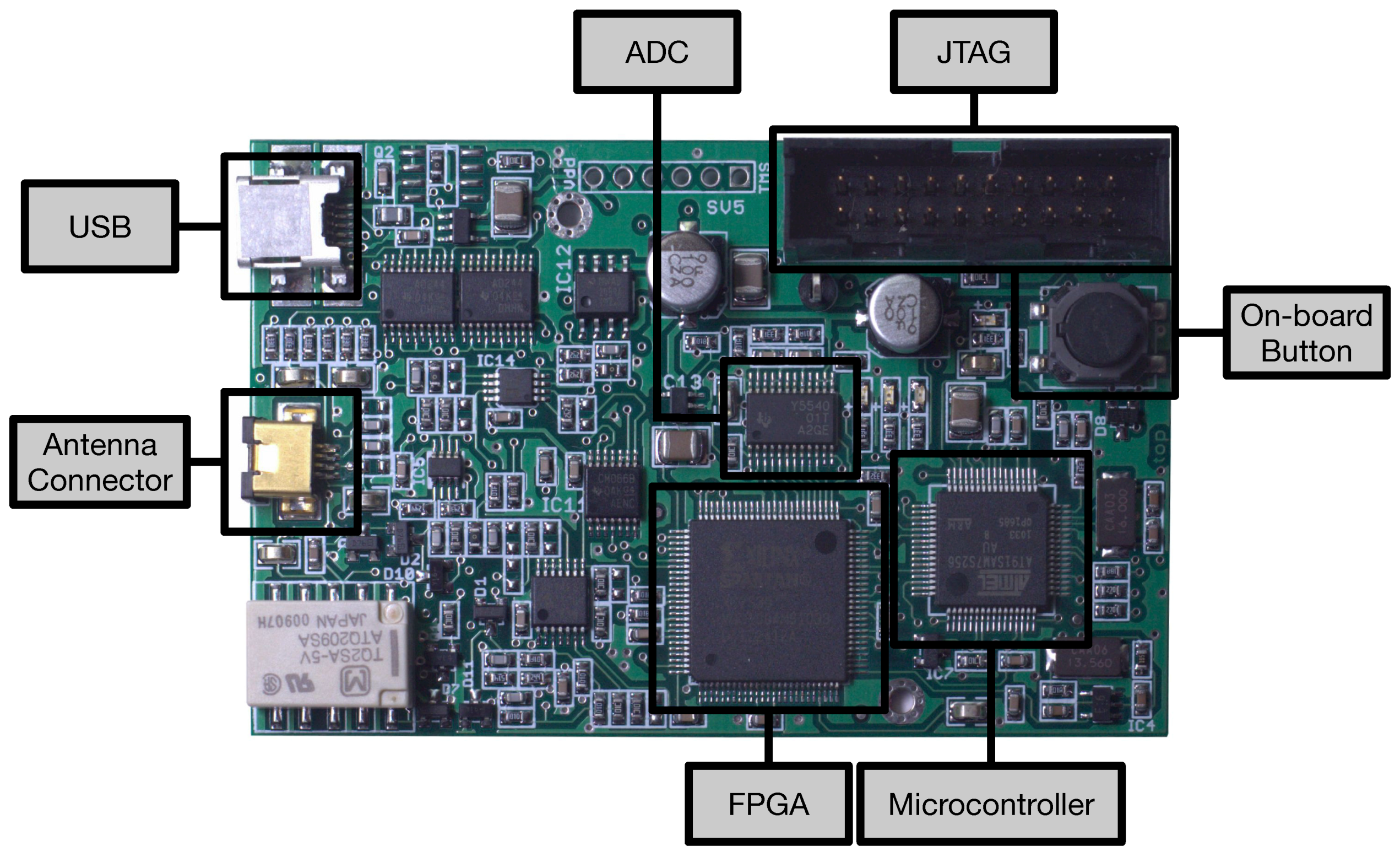
- The possibility of emulating diverse RFID communications protocols. The official firmware supports some basic protocols, but it is relatively easy to develop and upload new code to the embedded ARM microcontroller and to its FPGA.
- The community behind Proxmark 3, which has been extending the official firmware to add new features.
3. A Methodology for Reverse Engineering Communications Protocols and Auditing RFID Security
3.1. Objectives of the Methodology
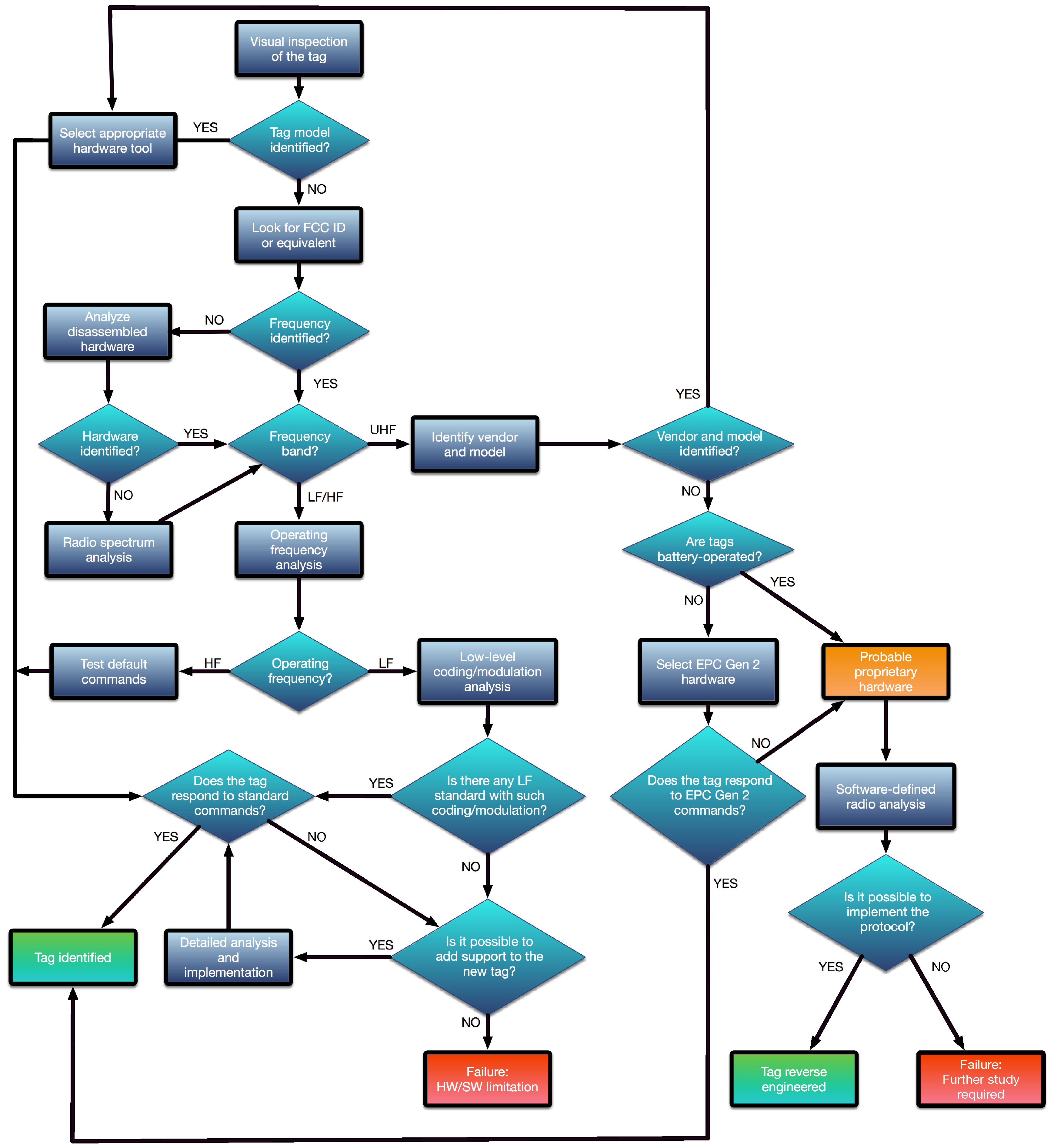
3.2. Basic Steps
- Visual inspection. Before analyzing the characteristics of a tag, it is first recommended to look for external signs that might indicate the manufacturer, the model, or the RFID standard. If any of such data is recognized, it is usually straightforward to obtain the basic parameters and details on the communications protocol.
- FCC (Federal Communications Commission) ID or equivalent. One of the most relevant external signs for determining the internal parameters of a tag is its FCC ID (or its equivalent in other parts of the world). The FCC is an agency of the United States that regulates radio communications. Each FCC-approved radio device receives a unique FCC ID that must be marked permanently and has to be visible to the buyer at the time of purchase. Such an FCC ID is composed by 4–17 alphanumeric characters. The first three characters are the Grantee Code, which identifies the company that asks for the authorization of the radio equipment. The rest of the characters (between 1 and 14) are the Product Code. If there is an FCC ID label on an RFID tag or on a reader, it is possible to obtain through the FCC ID search page [74] information like the name of the company that has applied for the authorization, the lower and upper operating frequencies, block diagrams, schematics, and even external/internal photos of the device.
- Frequency band detection. In most commercial systems it is not common to show external clues about the characteristics of a tag, so, in these cases, a detailed analysis has to be carried out. The first parameter to determine is the operation frequency of the tag. Most tags use LF, HF or UHF bands. If through the previous steps of the methodology it is not possible to determine the frequency, two additional processes can be performed:
- -
- Disassemble and analyze the hardware. This step aim is to study the internal components in order to determine the operation frequency. The most interesting elements are the ones related to the radio interface: transceivers, amplifiers, crystals, and filters allow us to determine the operation band and then estimate the frequency. In this case, transceiver datasheets are the fastest way to obtain an accurate frequency value. RFID readers are usually really easy to disassemble, but RFID tags require more sophisticated tools and techniques. An excellent description on how to disassemble and analyze an RFID tag is given in [22]. In such a paper the authors first use acetone to dissolve the external plastic encapsulation and isolate the blank chips. This process requires about half an hour, and it is easier and safer than other alternatives like the use of fuming nitric acid. Next, each layer of the silicon chips is removed through mechanical polishing (e.g., by using sandpaper), since it is easier to control than chemical etching. Note that very fine grading is required (e.g., m), because the layers can have a thickness of around a micrometer. Finally, after a successful polishing, the internal circuitry can be usually analyzed through a standard optical microscope.
- -
- Radio spectrum analysis. In this case, a spectrum or network analyzer, or an oscilloscope, is used to detect the operation frequency. The objective of such an analysis is to determine the resonant frequency of a passive RFID tag. The process models the RFID tag as a simple RLC parallel resonant circuit, what allows for obtaining the resonant frequency easily through Thomson equation:where L is the inductance and C is the capacitance. The key for measuring the resonant frequency is the fact that the impedance of the measuring antenna, the reflection coefficient (that measures how much of an electromagnetic wave is reflected by an impedance discontinuity), and the transmission coefficient (that measures how much of an electromagnetic wave passes through a surface) change significantly at frequencies in the vicinity of the RFID tag resonant frequency, . Therefore, the resonant frequency can be determined by scanning a frequency range and observing when these changes reach their peak. The whole process varies depending on the measurement equipment used, but some manufacturers ease it by offering step-by-step tutorials [75].There is also a cheaper option for carrying out this analysis that involves working with SDR (Software-Defined Radio) tools like the ones cited in Section 2.5, which can be reprogrammed to be used as spectrum analyzers. For instance, the USRP platform [76] has been proposed recently for spectrum monitoring [77] and sensing in cognitive radio applications [78,79], what can be re-purposed for RFID transmission frequency detection.
- LF/HF tag parameter analysis. If it is verified that the RFID system is LF or HF, the next step of the methodology requires determining the modulation and the coding scheme used by the tag. These tasks involve the use of the appropriate tool to perform a detailed analysis of the radio signals. Such a tool may be a bench oscilloscope with a measuring antenna or similar hardware (e.g., Proxmark 3) that allows for acquiring the RFID signals and then showing the wave received through a display. Thus, the identification is mainly visual, so the analysis becomes easier when the researcher has experience on recognizing the most common modulation and coding patterns. There also exists the possibility of using automatic recognition algorithms, which have been used for a long time (mainly in the military field) [80], but, very recently, they have been updated and improved to detect RFID physical layer characteristics [81,82].
- UHF tag parameter analysis. In the case of RFID UHF systems, the study can become difficult because, although most passive tags are compliant with the EPC Gen 2 standard, there are a number of companies that make use of proprietary protocols. In such a case, reverse engineering may require using SDR platforms like USRP, MyriadRF [83] or HackRF One [84] to study and then emulate the RFID communications protocol. In the case of the USRP platform, several researchers have presented really good references on how to implement USRP-based systems for identifying UHF tags over the last years [85,86].
- Standard analysis. Once the frequency, the modulation, and the coding scheme have been obtained, it is straightforward to determine whether there exists an RFID standard compliant with such a configuration. If there is not, the research may involve reverse engineering a proprietary protocol. However, due to compatibility purposes, most massively commercialized LF, HF and UHF tags follow well-known RFID standards. Table 1 provides a fast way to determine the RFID standard from the frequency, modulation and coding previously determined. Such a Table shows the wide variety of implementations, which include modulations like Amplitude-Shift Keying (ASK), Double-Sideband ASK (DSB-ASK), Single-Sideband ASK (SSB-ASK), Phase-Reversal ASK (PR-ASK), Frequency-Shift Keying (FSK), Binary-Phase Shift Keying (BPSK), Differential BPSK (DBPSK), Phase-Jitter Modulation (PJM), On-Off Keying (OOK) or Gaussian Minimum Shift Keying (GMSK); and coding schemes like Differential Bi-Phase (DBP), Dual Pattern (DP), Non-Return-to-Zero (NRZ), Non-Return-to-Zero-L (NRZ-L), Pulse-Interval Encoding (PIE), Manchester, Pulse-Position Modulation (PPM), Modified Frequency Modulation (MFM), modified Miller, or FM0.
- Sniff and emulate. The last step of the methodology is a trial and error process that requires to sniff and emulate communications to perform security tests. Sniffing is not only useful for reverse engineering a communications protocol, but also when trying to understand a well-documented standard protocol. Eventually, once the communications protocol is understood, it may be emulated with the appropriate hardware. For instance, Proxmark 3 official firmware offers off-the-shelf emulation of different standards (i.e., ISO/IEC 14443-A and 14443-B, ISO/IEC 15693) and specific tags (e.g., iClass, MIFARE, HID, Hitag, EM410x, Texas Instruments LF tags, or T55XX transponders). In the case of other platforms, an implementation of the reverse-engineered protocol may be necessary. For example, two cases of UHF RFID tag emulation using an USRP platform are presented in [85,86].
3.3. A Practical Approach to the Methodology Using Proxmark 3
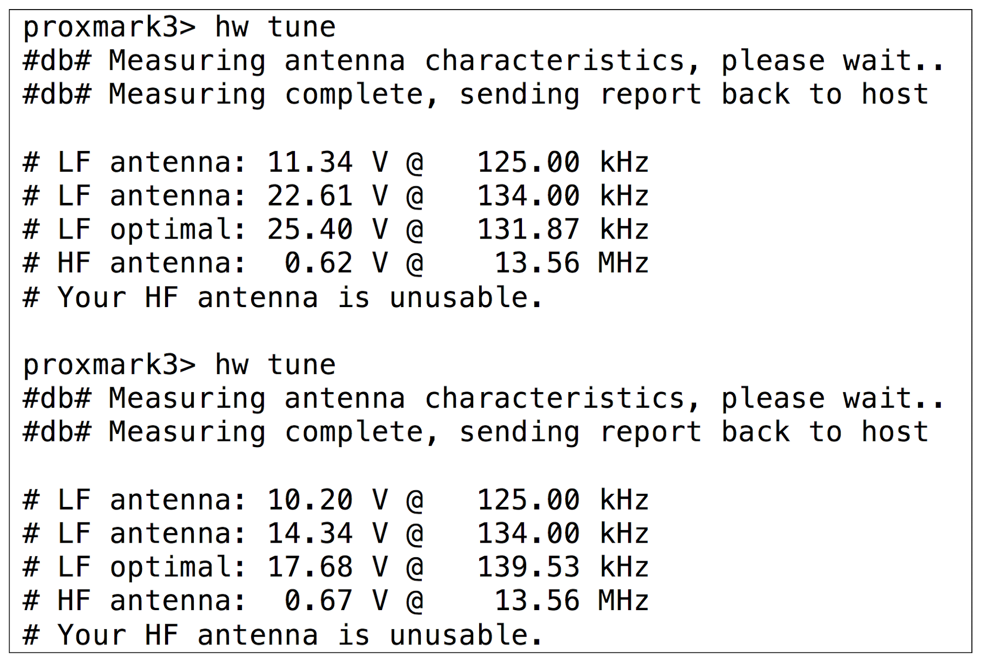
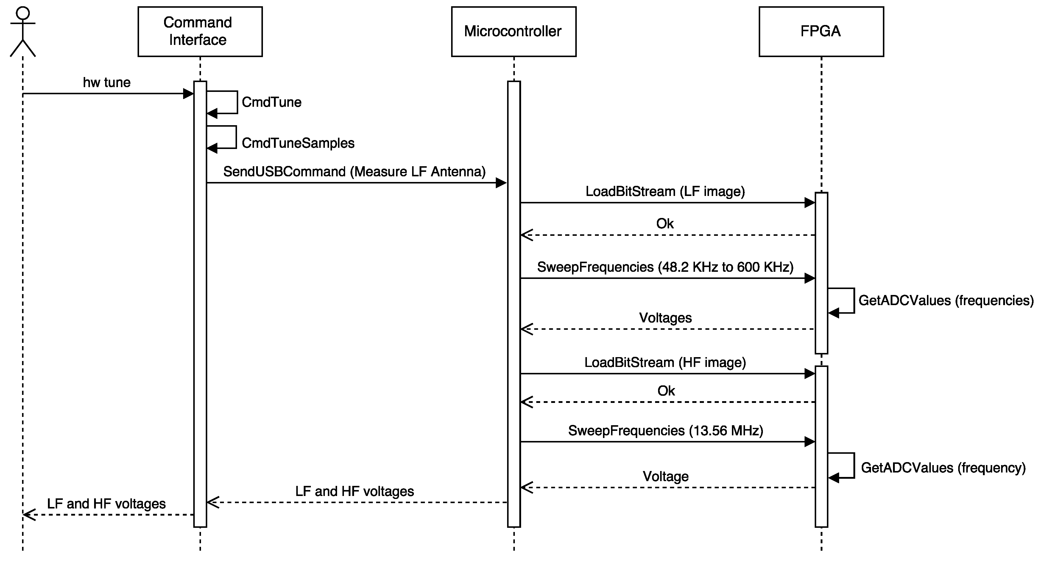
3.3.1. Detecting the Operating Frequency
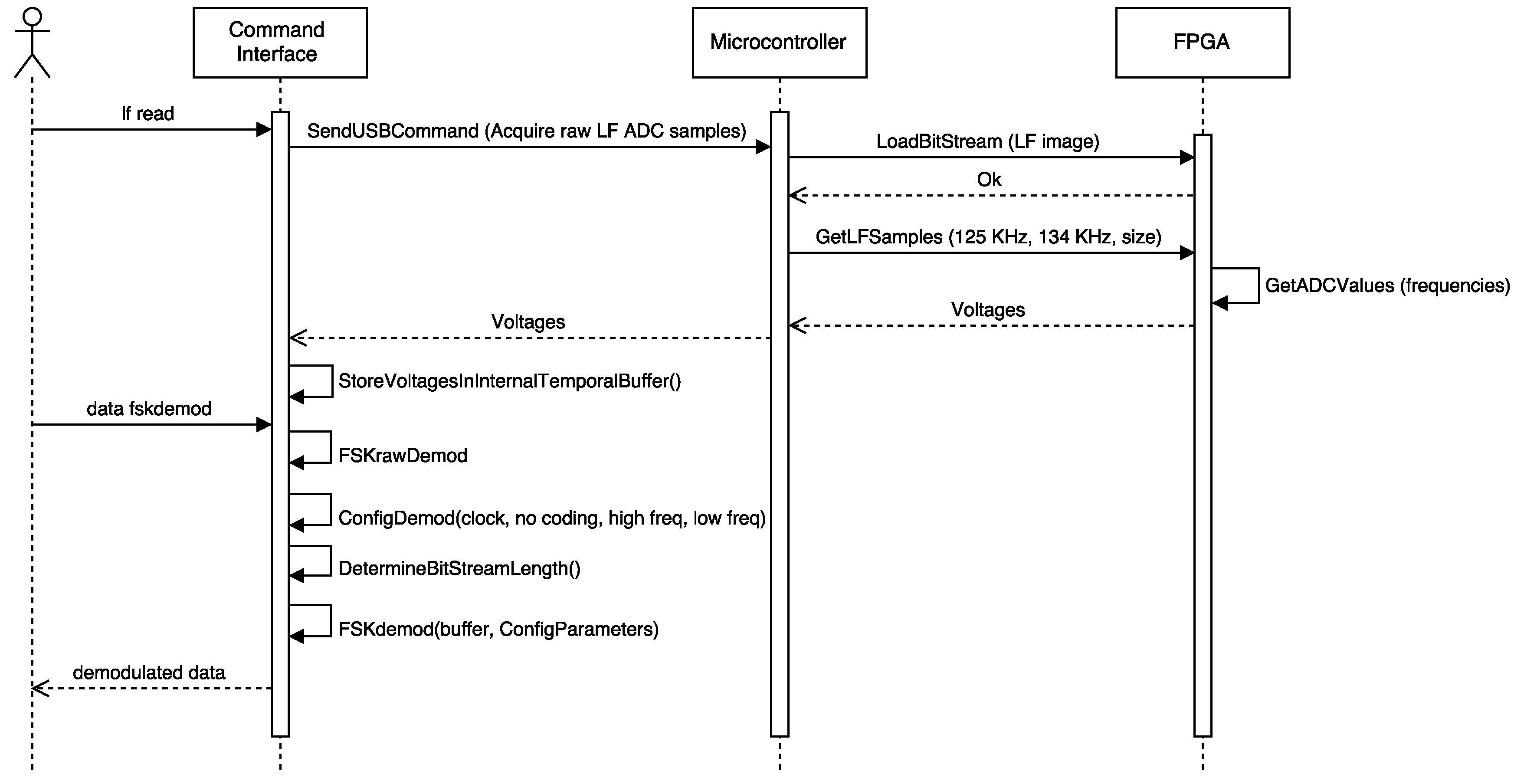
3.3.2. LF Tag Analysis
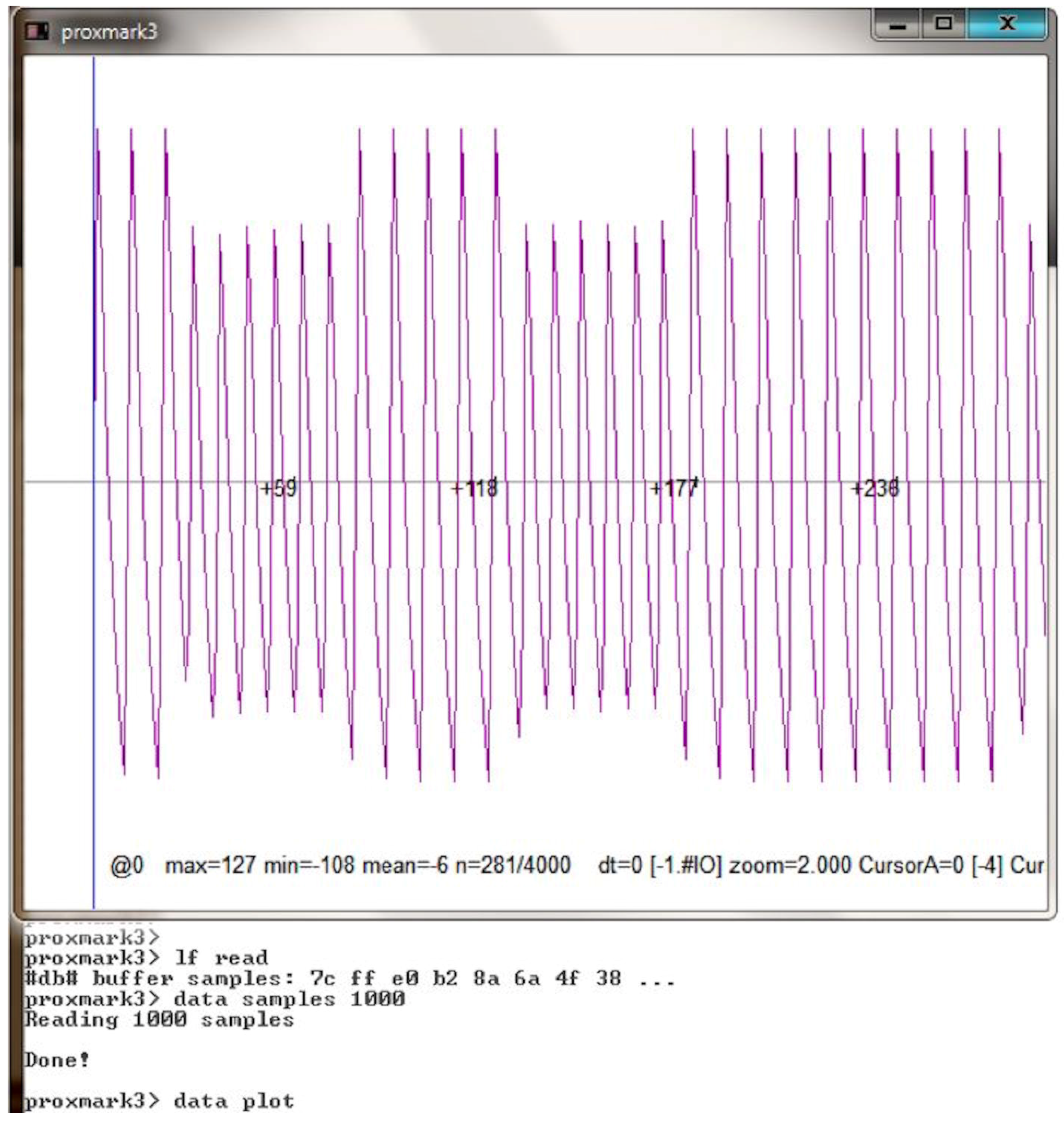
- LF read [h]: the tag is powered at the selected frequency (125 kHz by default, or 134 kHz using the optional parameter h). The command also records the signal transmitted by the tag.
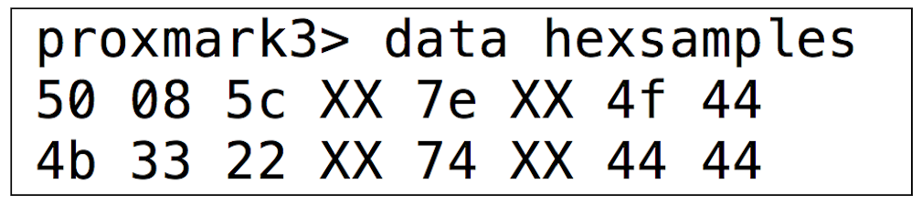
- Data sample x: it downloads x of the previously recorded samples to the PC.
- Data plot. It allows the user to open a new window to plot the signal. It is useful for evaluating the signal visually.
- Different instructions can be used to modify, amplify, decimate or normalize signal values to ease signal identification.
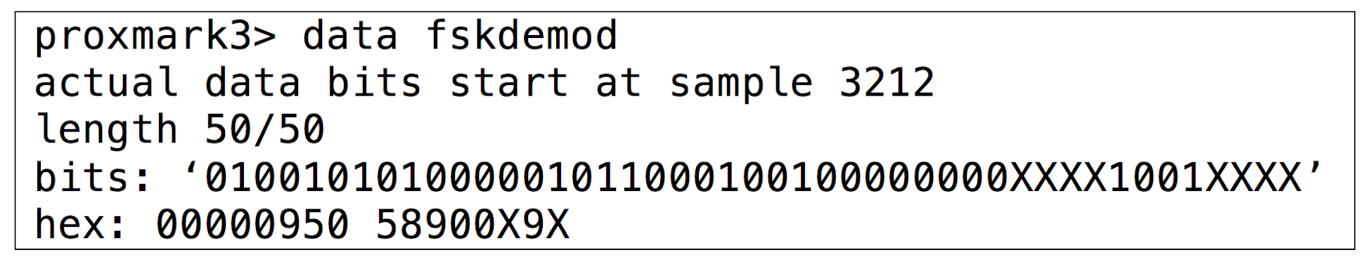
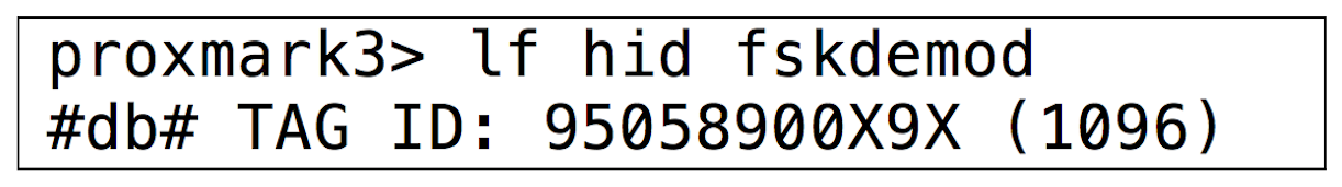
- If the signal is clean enough and its modulation has been recognized, the user can try to demodulate it. For instance, if the signal is modulated in ASK, the command “askdemod” can be executed. In the case of FSK modulated signals, “fskdemod“ is the right command.
3.3.3. HF Tag Analysis
4. Practical Evaluation
4.1. HID Proximity Cards
4.1.1. Visual Inspection and FCC ID
4.1.2. Analysis of Disassembled Hardware and Radio Spectrum Analysis
4.1.3. Operating Frequency and Modulation
- Radio frequency. The steps described in Section 3.3.1 were carried out and determined that it was an LF tag.
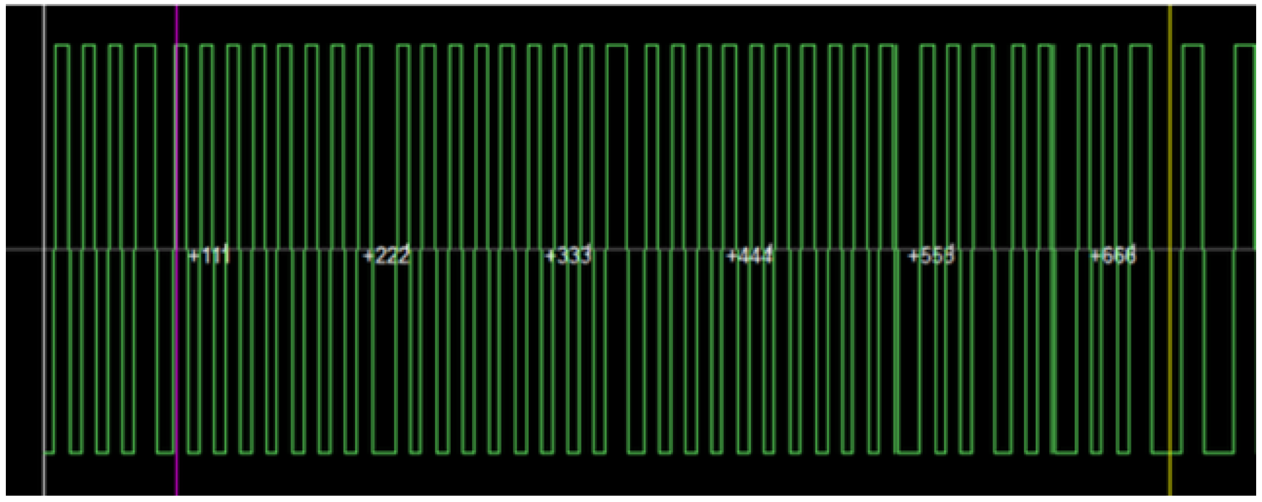
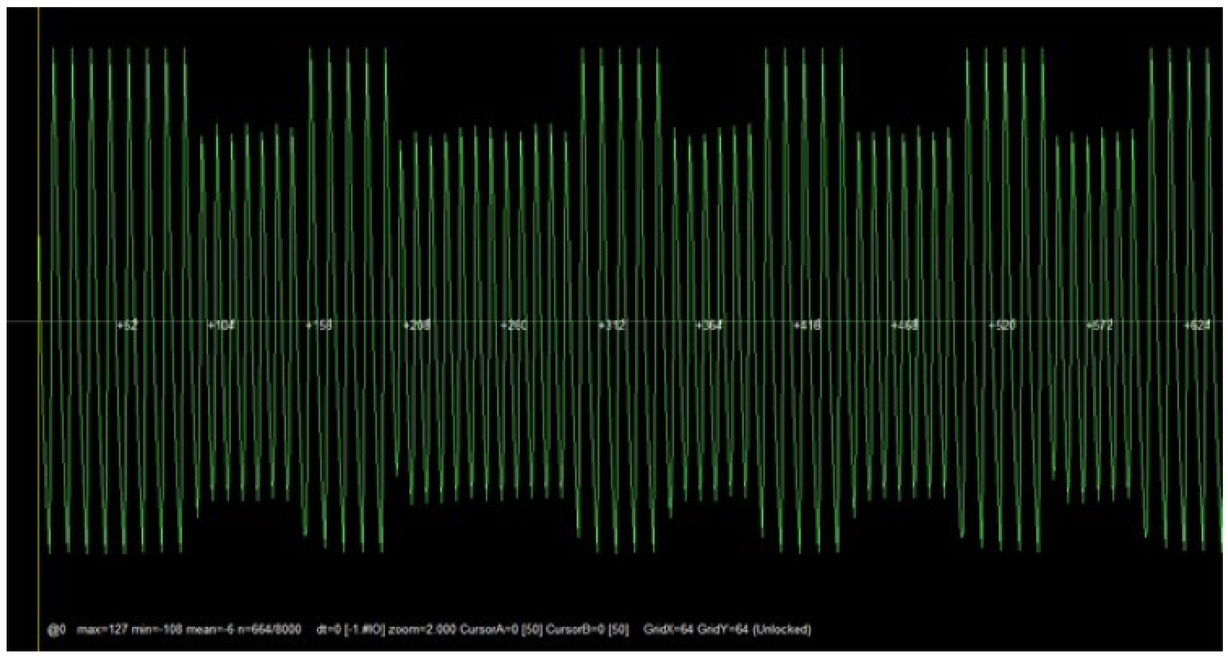
- Modulation. Once the radio frequency was obtained, a visual analysis of the signal received was performed to determine the modulation of the tag. Figure 15 allows us to conclude that the signal was modulated in FSK. In fact, it used a center frequency (fc) of 125 kHz and two sub-frequencies, fc/8 and fc/10. Note that the signal shown in Figure 15 may seem initially an ASK wave, but after zooming in, it can be observed that the time period of the wider waves is larger than the one of the shorter waves.
4.1.4. Understanding the Underlying Protocols
- The header follows a fixed pattern: 12 high-frequency (fc/8) pulses are first followed by a “0”, and then 10 low-frequency (fc/10) pulses are followed by another “0”.
- A “0” is coded with 5 low-frequency pulses followed by 5 high-frequency pulses.
- A “1” is coded with 6 high-frequency pulses followed by 6 low-frequency pulses.
- Every 4 data bits a high-frequency pulse is inserted.
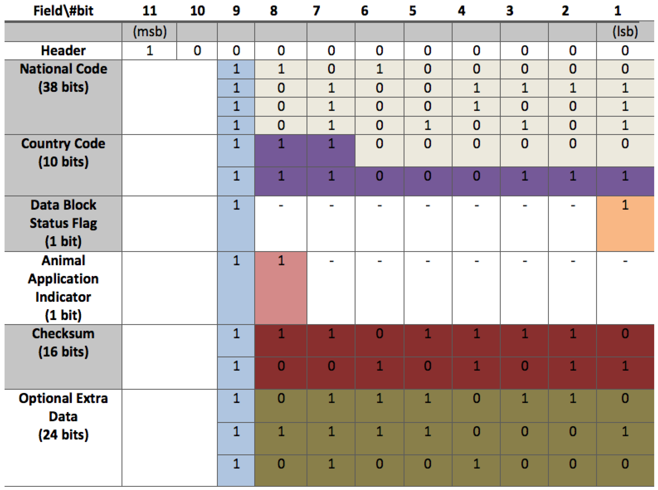
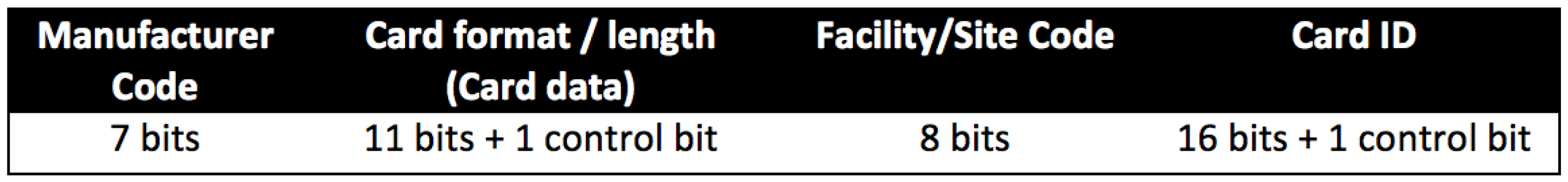
- There are 44 data bits structured as indicated in Figure 16.
4.1.5. Security Analysis
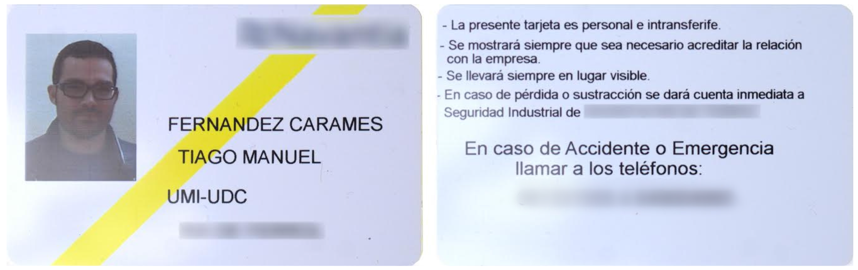
4.2. University of A Coruña’s RFID Card
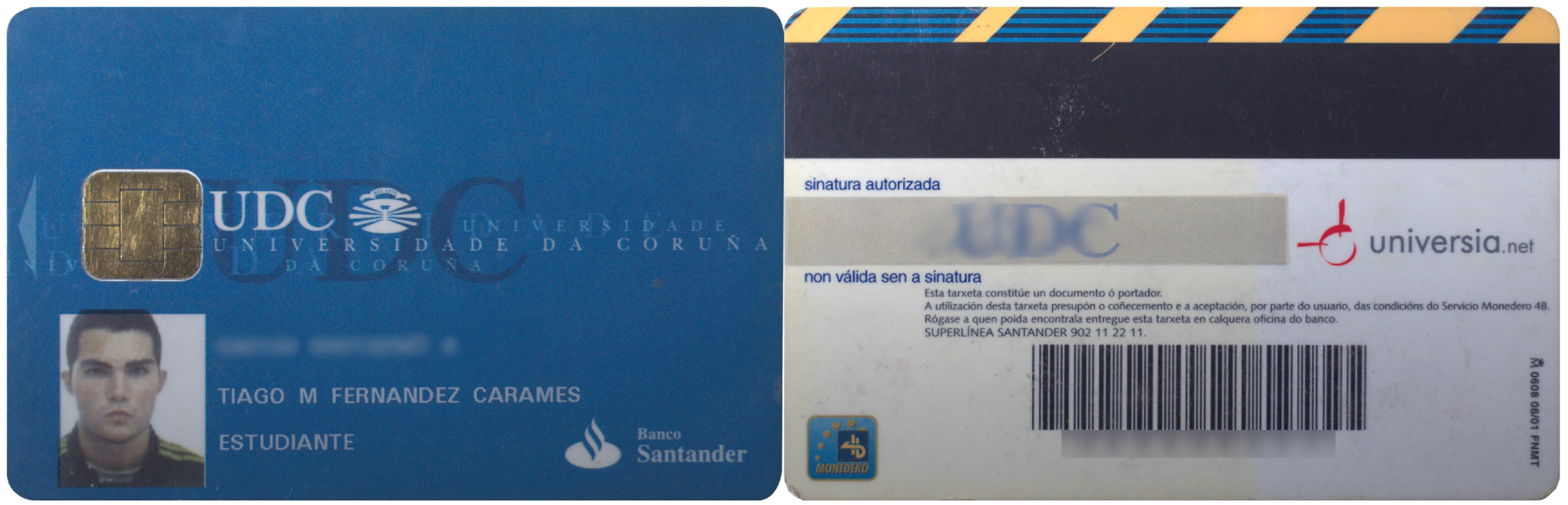
4.2.1. Visual Inspection and FCC ID
4.2.2. Analysis of Disassembled Hardware and Radio Spectrum Analysis
4.2.3. Operating Frequency and Modulation
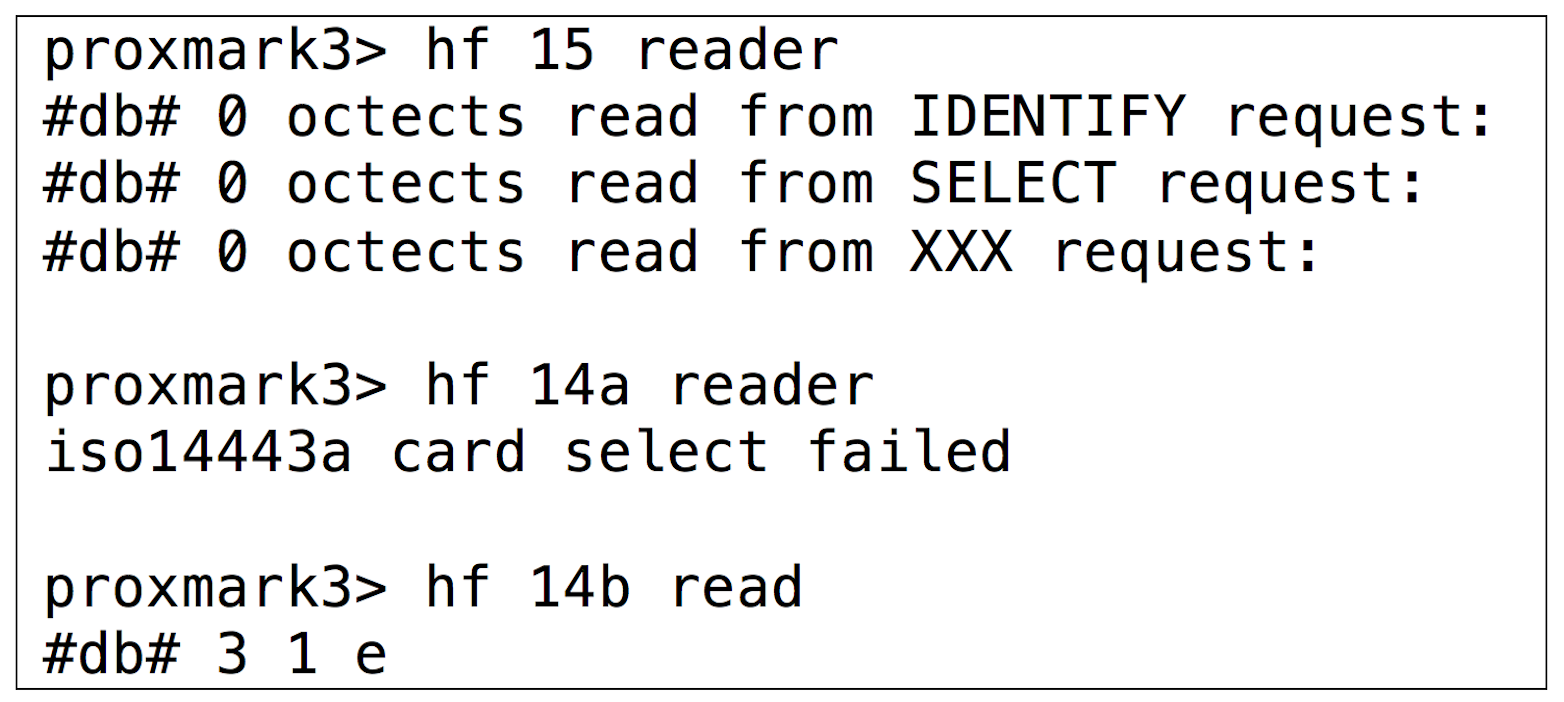
- Operating frequency. The verification steps described in Section 3.3.1 allowed us to conclude that it was an HF card.
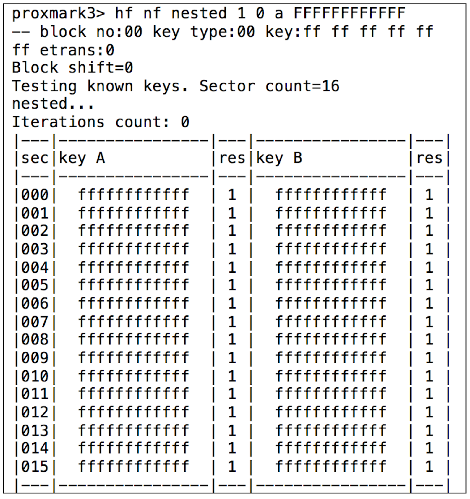
- Modulation. Once determined the frequency band, it was possible to test the commands for the different ISO/IEC standards. After testing the ones for ISO/IEC 14443-B and ISO/IEC 15693, it was found that the tag responded correctly to ISO/IEC 14443-A commands, which indicated that the tag was a MIFARE Classic 1K.
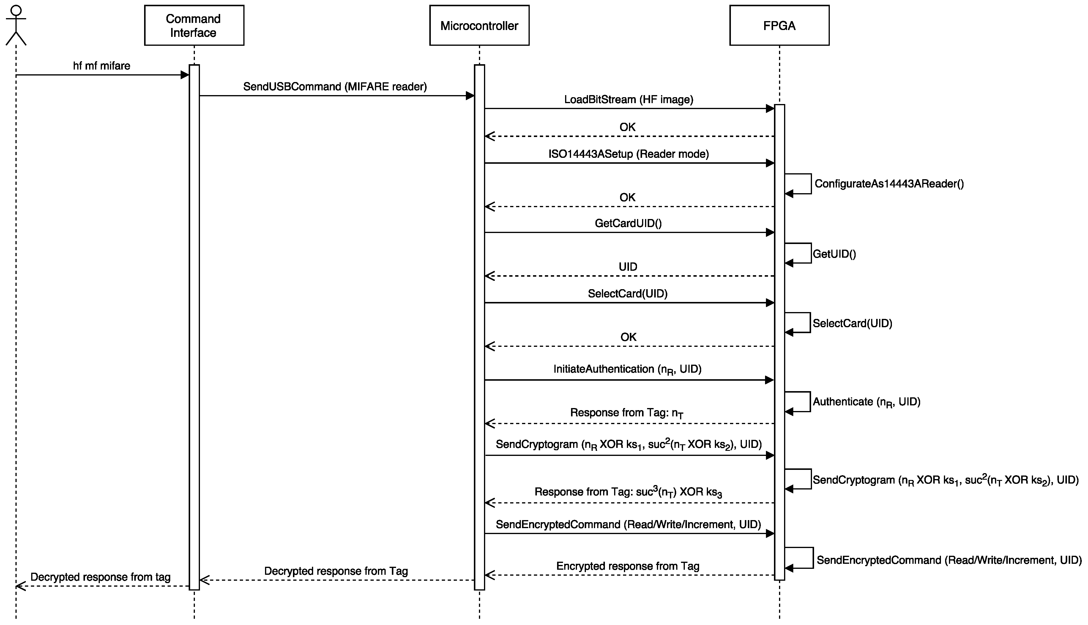
4.2.4. Understanding the Underlying Protocols
- MIFARE Classic 1K. Its name derives from its 1024-byte internal storage, which is divided into 16 64-byte sectors.
- MIFARE Classic 4K. It has 4096 bytes for data divided into 40 sectors.
- MIFARE Classic Mini. It stores 320 bytes in 5 sectors (the actual useful data space is 224 bytes).
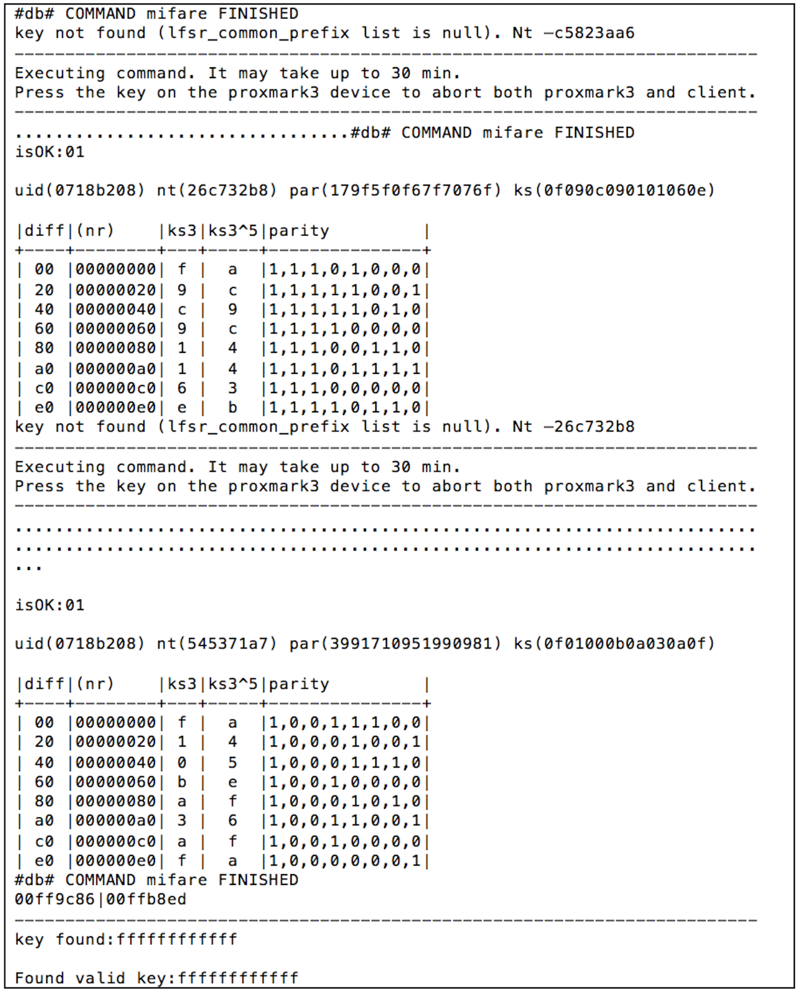
4.2.5. Security Analysis
4.3. European Animal Identification Tags
4.3.1. Visual Inspection and FCC ID
4.3.2. Detailed Analysis
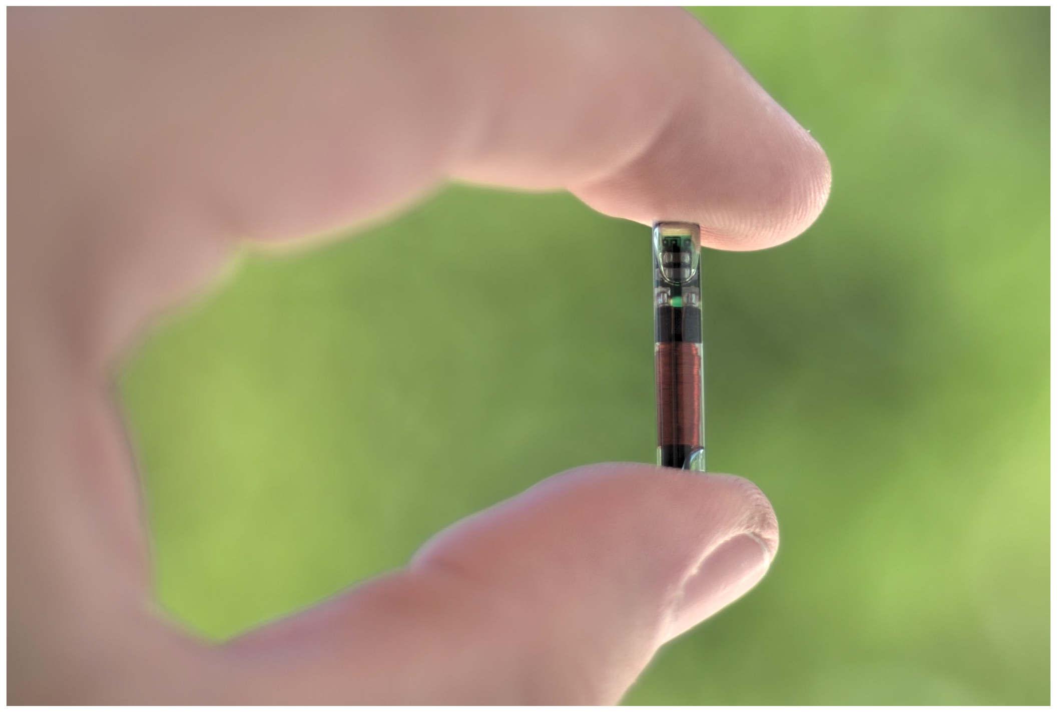
- Operating frequency. With the help of the Proxmark 3 a tag implanted in a dog was verified. As expected, it was determined that it was LF.
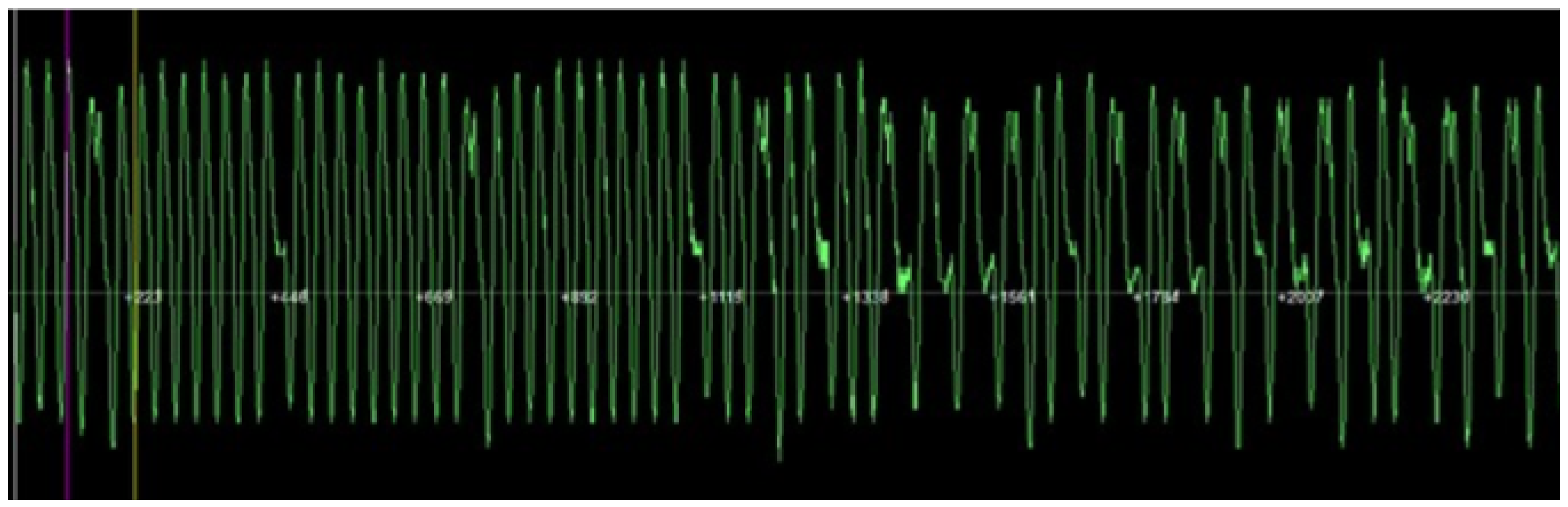
- Modulation. It was not straightforward to recognize the modulation, since the signals received were very noisy (it must be noted that the tag had been implanted a year before the tests were performed). Figure 22 illustrates the noise level on the signals received. Due to such noise, it was necessary to filter the signal, obtaining a figure like the one shown in Figure 23, which resembles the expected bi-phase encoding.
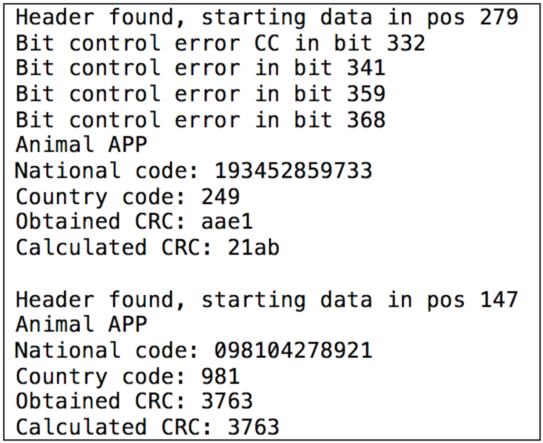
4.3.3. Understanding the Underlying Protocols
4.3.4. Security Evaluation
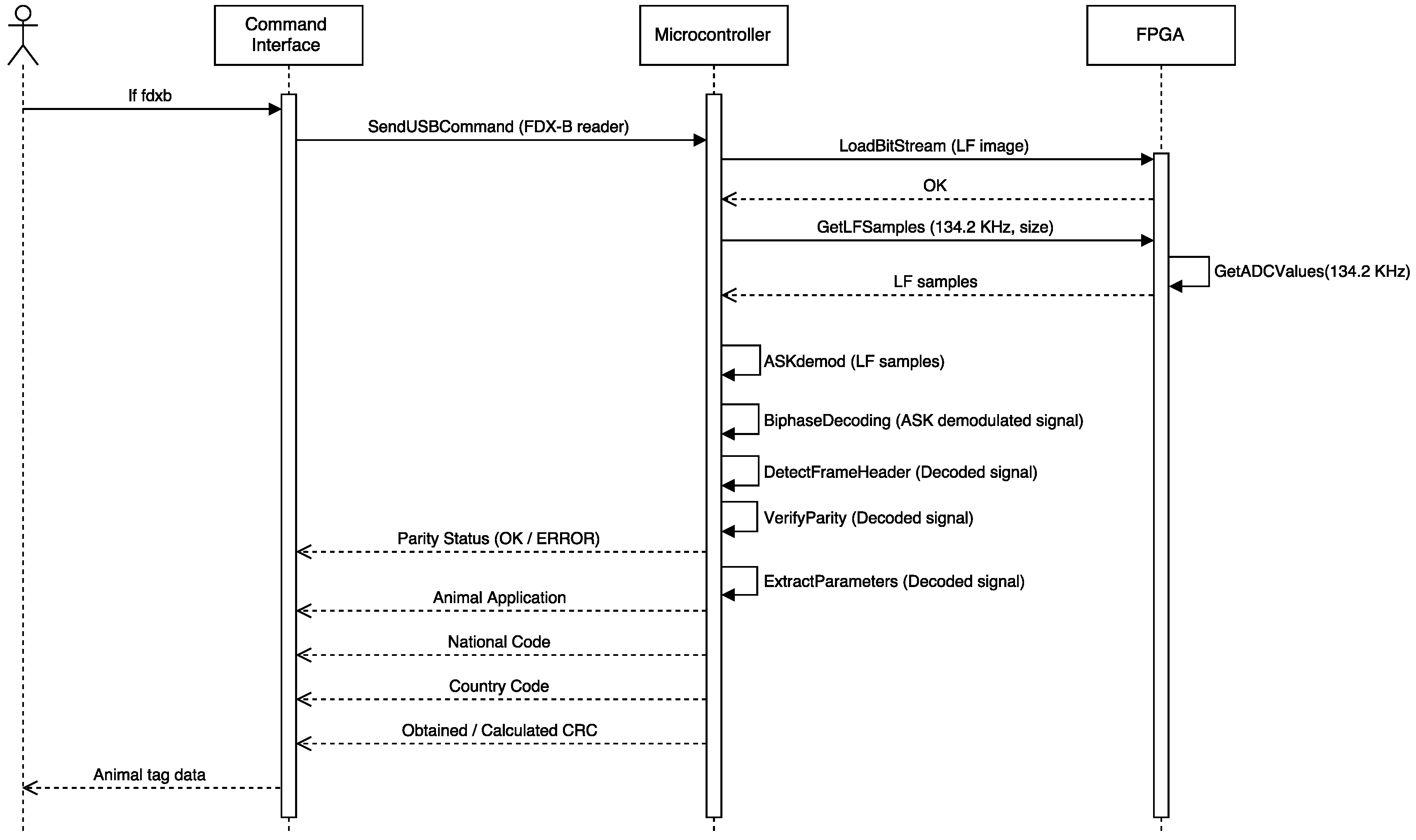
- Modify the original Proxmark 3 client application (programmed in C) to offer users a new function to perform FDX-B demodulation.
- Modify the original Proxmark 3 microcontroller firmware (also programmed in C) to create an FDX-B demodulation function that first demodulates the ASK signal and then decodes the DBP bit stream. It was not necessary to reprogram the FPGA firmware. However, this FDX-B demodulation function requires to manage the input/output and the exchange memory buffers used by the already-available FPGA functions to perform the operations as fast as possible.
- ASK demodulation was already available in the original firmware, but it was necessary to modify the Proxmark 3 microcontroller firmware to implement the DBP decoding function.
5. Conclusions
Acknowledgments
Author Contributions
Conflicts of Interest
Abbreviations
| ADC | Analog-to-Digital Converter |
| ASIC | Application-Specific Integrated Circuit |
| ASK | Amplitude-Shift Keying |
| BPSK | Binary-Phase Shift Keying |
| CRC | Cyclic-Redundancy Check |
| DBP | Differential Bi-Phase |
| DBPSK | Differential BPSK |
| DP | Dual Pattern |
| DSB-ASK | Double-Sideband ASK |
| DoS | Denial of Service |
| FPGA | Field-Programmable Gate Array |
| FSK | Frequency-Shift Keying |
| GMSK | Gaussian Minimum Shift Keying |
| HF | High Frequency |
| ITS | Intelligent Transportation Systems |
| LF | Low Frequency |
| LSB | Less-Significant Bit |
| MAC | Medium Access Control |
| MitM | Man-in-the-Middle |
| MFM | Modified Frequency Modulation |
| NACK | Negative Acknowledgment |
| NRZ | Non-Return-to-Zero |
| NRZ-L | Non-Return-to-Zero-L |
| OOK | On-Off Keying |
| PIE | Pulse-Interval Encoding |
| PJM | Phase-Jitter Modulation |
| PPM | Pulse-Position Modulation |
| PR-ASK | Phase-Reversal ASK |
| RFID | Radio Frequency Identification |
| SHF | Super-High Frequency |
| SSB-ASK | Single-Sideband ASK |
| UHF | Ultra-High Frequency |
| UID | Unique Identifier |
References
- Floyd, R.E. RFID in animal-tracking applications. IEEE Potentials 2015, 34, 32–33. [Google Scholar] [CrossRef]
- Madanian, S. The use of e-health technology in healthcare environment: The role of RFID technology. In Proceedings of the 10th International Conference on e-Commerce in Developing Countries: With Focus on e-Tourism, Isfahan, Iran, 15–16 April 2016; pp. 1–5.
- Ezovski, G.M.; Watkins, S.E. The electronic passport and the future of government-issued RFID-based identification. In Proceedings of the IEEE International Conference on RFID, Grapevine, TX, USA, 26–28 March 2007; pp. 15–22.
- Floyd, R.E. RFID in transportation. IEEE Potentials 2015, 34, 19–21. [Google Scholar] [CrossRef]
- Feng, T. An agri-food supply chain traceability system for China based on RFID and blockchain technology. In Proceedings of the 13th International Conference on Service Systems and Service Management, Kumming, China, 24–26 June 2016; pp. 1–6.
- Shen, J.; Tan, X.; Wu, F.; Yan, P. RFID cardinality estimation method for intelligent warehouse. In Proceedings of the 35th Chinese Control Conference, Chengdu, China, 27–29 July 2016; pp. 8468–8473.
- Barro-Torres, S.J.; Fernández-Caramés, T.M.; Gonález-López, M.; Escudero-Cascón, C.J. Maritime Freight Container Management System Using RFID. In Proceedings of the 3rd International EURASIP Workshop on RFID Technology, La Manga del Mar Menor, Spain, 6–7 September 2010.
- Barro-Torres, S.J.; Fernández-Caramés, T.M.; Pérez-Iglesias, H.J.; Escudero, C.J. Real-time personal protective equipment monitoring system. Comput. Commun. 2012, 36, 42–50. [Google Scholar] [CrossRef]
- Blythe, P. RFID for road tolling, road-use pricing and vehicle access control. In Proceedings of the IEE Colloquium on RFID Technology (Ref. No. 1999/123), London, UK, 25 October 1999.
- Xu, G. The Research and Application of RFID Technologies in Highway’s Electronic Toll Collection System. In Proceedings of the 4th International Conference on Wireless Communications, Networking and Mobile Computing, Dalian, China, 12–17 October 2008; pp. 1–4.
- Sun, C. Application of RFID Technology for Logistics on Internet of Things. In Proceedings of the AASRI Conference on Computational Intelligence and Bioinformatics, Changsha, China, 1–2 July 2012; pp. 106–111.
- Leal, A.G.; Santiago, A.; Miyake, M.Y.; Noda, M.K.; Pereira, M.J.; Avanço, L. Integrated environment for testing IoT and RFID technologies applied on intelligent transportation system in Brazilian scenarios. In Proceedings of the IEEE Brasil RFID, Sao Paulo, Brazil, 25 September 2014; pp. 22–24.
- Amendola, S.; Lodato, R.; Manzari, S.; Occhiuzzi, C.; Marrocco, G. RFID Technology for IoT-Based Personal Healthcare in Smart Spaces. IEEE Internet Things J. 2014, 1, 144–152. [Google Scholar] [CrossRef] [Green Version]
- Bagula, A.; Castelli, L.; Zennaro, M. On the design of smart parking networks in the smart cities: An optimal sensor placement model. Sensors 2015, 15, 15443–15467. [Google Scholar] [CrossRef] [PubMed] [Green Version]
- Fraga-Lamas, P.; Fernández-Caramés, T.M.; Suárez-Albela, M.; Castedo, L.; González-López, M. A review on internet of things for defense and public safety. Sensors 2016, 16, 1644. [Google Scholar] [CrossRef] [PubMed]
- Trcek, D. Wireless sensors grouping proofs for medical care and ambient assisted-living deployment. Sensors 2016, 16, 33. [Google Scholar] [CrossRef] [PubMed]
- Fernández-Caramés, T.M. An intelligent power outlet system for the smart home of the internet of things. Int. J. Distrib. Sens. Netw. 2015, 2015, 1. [Google Scholar] [CrossRef] [PubMed]
- Prinsloo, J.; Malekian, R. Accurate vehicle location system using RFID, an internet of things approach. Sensors 2016, 16, 825. [Google Scholar] [CrossRef] [PubMed]
- Li, H.; Chen, Y.; He, Z. The survey of RFID attacks and defenses. In Proceedings of the 8th International Conference on Wireless Communications, Networking and Mobile Computing, Shanghai, China, 21–23 September 2012; pp. 1–4.
- Pandian, M.T.; Sukumar, R. RFID: An appraisal of malevolent attacks on RFID security system and its resurgence. In Proceedings of the IEEE International Conference in MOOC Innovation and Technology in Education (MITE), Jaipur, India, 20–22 December 2013; pp. 17–20.
- Oren, Y. Remote password extraction from RFID tags. IEEE Trans. Comput. 2007, 56, 1292–1296. [Google Scholar] [CrossRef]
- Nohl, K.; Evans, D.; Plötz, S.; Plötz, H. Reverse-engineering a cryptographic RFID tag. In Proceedings of the 17th USENIX Security Symposium, San José, CA, USA, 28 July–1 August 2008; pp. 185–193.
- Hutter, M.; Schmidt, J.M.; Plos, T. Contact-based fault injections and power analysis on RFID tags. In Proceedings of the European Conference on Circuit Theory and Design, Antalya, Turkey, 23–27 August 2009; pp. 409–412.
- Vojtech, L.; Kahl, J. Power analysis of communication of RFID transponders with Password-Protected Memory. In Proceedings of the Eighth International Conference on Networks, Gosier, France, 1–6 March 2009; pp. 116–120.
- Mednis, A.; Zviedris, R. RFID communication: How well protected against reverse engineering? In Proceedings of the Second International Conference on Digital Information Processing and Communications, Klaipeda City, Latvia, 10–12 July 2012; pp. 59–61.
- Yeh, K.-H.; Lo, N.-W.; Wu, T.-C.; Wang, C. Secure e-health system on passive RFID: Outpatient clinic and emergency care. Int. J. Distrib. Sens. Netw. 2013, 9. [Google Scholar] [CrossRef]
- Suh, W.S.; Yoon, E.J.; Piramuthu, S. RFID-based attack scenarios in retailing, healthcare and sports. J. Inf. Priv. Sec. 2013, 9, 4–17. [Google Scholar] [CrossRef]
- Kim, J.T. Attacks and threats on the U-healthcare application with mobile agent. Int. J. Sec. Appl. 2014, 8, 59–66. [Google Scholar] [CrossRef]
- Rosenbaum, B.P. Radio Frequency Identification (RFID) in health care: Privacy and security concerns limiting adoption. J. Med. Syst. 2014, 38, 19. [Google Scholar] [CrossRef] [PubMed]
- Xiao, Q.; Boulet, C.; Gibbons, T. RFID Security Issues in Military Supply Chains. In Proceedings of the International Conference on Availability, Reliability and Security, Vienna, Austria, 10–13 April 2007; pp. 599–605.
- Xiao, Q.; Gibbons, T.; Lebrun, H. RFID Technology, Security Vulnerabilities, and Countermeasures. In Supply Chain the Way to Flat Organisation, 1st ed.; Huo, Y., Jia, F., Eds.; INTECH: Rijeka, Croatia, 2009. [Google Scholar]
- Sen, D.; Sen, P.; Das, A. RFID for Energy & Utility Industries, 1st ed.; Huo, Y., Jia, F., Eds.; PennWell: Tulsa, OK, USA, 2009. [Google Scholar]
- Francillon, A.; Danev, B.; Capkun, S. Relay Attacks on Passive Keyless Entry and Start Systems in Modern Cars. In Proceedings of the Network and Distributed System Security Symposium (NDSS 2011), San Diego, CA, USA, 6–9 February 2011.
- Checkoway, S.; McCoy, D.; Kantor, B.; Anderson, D.; Shacham, H.; Savage, S.; Koscher, K.; Czeskis, A.; Roesner, F.; Kohno, T. Comprehensive Experimental Analyses of Automotive Attack Surfaces. In Proceedings of the 20th USENIX conference on Security, San Francisco, CA, USA, 8–12 August 2011.
- Amariucai, G.T.; Bergman, C.; Guan, Y. An Automatic, Time-based, Secure Pairing Protocol for Passive RFID. In Proceedings of the 7th International Conference on RFID Security and Privacy, Amherst, MA, USA, 26–28 June 2011.
- Unluturk, M.S.; Kurtel, K. Integration of RFID and web service for assisted living. J. Med. Syst. 2012, 36, 2371–2377. [Google Scholar] [CrossRef] [PubMed]
- Ijaz, S.; Shah, M.A.; Khan, A.; Ahmed, M. Smart cities: A survey on security concerns. Int. J. Adv. Comput. Sci. Appl. 2016, 7, 612–625. [Google Scholar] [CrossRef]
- Hancke, G.P. Practical attacks on proximity identification systems. In Proceedings of the IEEE Symposium on Security and Privacy, Berkeley, CA, USA, 21–24 May 2006.
- Feldhofer, M.; Aigner, M.; Baier, T.; Hutter, M.; Plos, T.; Wenger, E. Semi-passive RFID development platform for implementing and attacking security tags. In Proceedings of the International Conference for Internet Technology and Secured Transactions, London, UK, 8–11 November 2010; pp. 1–6.
- Chawla, K.; Robins, G. Addressing Covert Channel Attacks in RFID-Enabled Supply Chains. In Advanced Security and Privacy for RFID Technologies, 1st ed.; Miri, A., Ed.; IGI Global: Hershey, PA, USA, 2013. [Google Scholar]
- Nayak, R.; Singh, A.; Padhye, R.; Wang, L. RFID in textile and clothing manufacturing: Technology and challenges. Fash. Text. 2015, 2, 9. [Google Scholar] [CrossRef]
- Koning Gans, G. Analysis of the MIFARE Classic Used in the OV-Chipkaart Project. Master’s Thesis, Radboud University Nijmegen, Nijmegen, The Netherlands, 2008. [Google Scholar]
- Garcia, F.D.; van Rossum, P.; Verdult, R.; Schreur, R.W. Wirelessly pickpocketing a Mifare Classic card. In Proceedings of the IEEE Symposium on Security and Privacy, Oakland, CA, USA, 17–20 May 2009; pp. 3–15.
- Courtois, N. The dark side of security by obscurity and cloning Mifare Classic rail and building passes, anywhere, anytime. In Proceedings of the International Conference on Security and Cryptography, Milan, Italy, 7–10 July 2009.
- Oswald, D.; Paar, C. Breaking Mifare DESFire MF3ICD40: Power analysis and templates in the real world. Lect. Notes Comput. Sci. 2011, 6917, 207–222. [Google Scholar]
- Garcia, F.D.; Gans, G.K.; Muijrers, R.; Rossum, P.; Verdult, R.; Schreur, R.W.; Jacobs, B. Dismantling MIFARE card. In Proceedings of the European Symposium on Research in Computer Security, Torremolinos, Spain, 6–8 October 2008; pp. 97–114.
- Wang, B.; Zhang, J.; Sun, X.; Wang, N.; Zhao, Y.; Wang, F. Research on authentication technology of agriculture products traceability system based on RFID. Chem. Eng. Trans. 2015, 46, 1357–1362. [Google Scholar]
- Eisenbarth, T.; Kumar, S. A survey of lightweight-cryptography implementations. IEEE Des. Test Comput. 2007, 24, 522–533. [Google Scholar] [CrossRef]
- Ray, B.; Huda, S.; Chowdhury, M.U. Smart RFID reader protocol for malware detection. In Proceedings of the 12th ACIS International Conference on Software Engineering, Artificial Intelligence, Networking and Parallel/Distributed Computing, Sydney, Australia, 6–8 July 2011; pp. 64–69.
- Abawajy, J. Enhancing RFID tag resistance against cloning attack. In Proceedings of the 3rd International Conference on Network and System Security, Gold Coast, Australia, 19–21 October 2009; pp. 18–23.
- Avanco, L.; Guelfi, A.E.; Pontes, E.; Silva, A.A.A.; Kofuji, S.T.; Zhou, F. An effective intrusion detection approach for jamming attacks on RFID systems. In Proceedings of the International EURASIP Workshop on RFID Technology (EURFID), Rosenheim, Germany, 22–23 October 2015; pp. 73–80.
- Bilal, Z.; Martin, K. Ultra-lightweight mutual authentication protocols: Weaknesses and Countermeasures. In Proceedings of the Eighth International Conference on Availability, Reliability and Security, Regensburg, Germany, 2–6 September 2013; pp. 304–309.
- Fernández-Caramés, T.M.; Fraga-Lamas, P.; Suárez-Albela, M.; Castedo, L. A methodology for evaluating security in commercial RFID systems. In Radio Frequency Identification, 1st ed.; Crepaldi, P.C., Pimenta, T.C., Eds.; INTECH: Rijeka, Croatia, 2016. [Google Scholar]
- Roberts, C.M. Radio frequency identification (RFID). Comput. Sec. 2006, 25, 18–26. [Google Scholar] [CrossRef]
- Lim, T.L.; Li, T. Exposing an effective denial of information attack from the misuse of EPCglobal standards in an RFID authentication scheme. In Proceedings of the IEEE 19th International Symposium on Personal, Indoor and Mobile Radio Communications, Cannes, France, 15–18 September 2008; pp. 1–6.
- Bu, K.; Liu, X.; Luo, J.; Xiao, B.; Wei, G. Unreconciled collisions uncover cloning attacks in anonymous RFID systems. IEEE Trans. Inf. Forensics Sec. 2013, 8, 429–439. [Google Scholar] [CrossRef]
- Suliman, A.; Shankarapani, M.K.; Mukkamala, S.; Sung, A.H. RFID malware fragmentation attacks. In Proceedings of the International Symposium on Collaborative Technologies and Systems, Irvine, CA, USA, 19–23 May 2008; pp. 533–539.
- Halevi, T.; Li, H.; Ma, D.; Saxena, N.; Voris, J.; Xiang, T. Context-aware defenses to RFID unauthorized reading and relay attacks. IEEE Trans. Emerg. Top. Comput. 2013, 1, 307–318. [Google Scholar] [CrossRef]
- Ayoade, J. Security implications in RFID and authentication processing framework. Comput. Sec. 2006, 25, 207–212. [Google Scholar] [CrossRef]
- Weiß, M. Performing Relay Attacks on ISO 14443 Contactless Smart Cards Using NFC Mobile Equipment. Master’s Thesis, Technische Universität München, Munich, Germany, 2010. [Google Scholar]
- Guizani, S. Implementation of an RFID relay attack countermeasure. In Proceedings of the International Wireless Communications and Mobile Computing Conference, Dubrovnik, Croatia, 24–28 August 2015; pp. 1318–1323.
- Hancke, G.P.; Mayes, K.E.; Markantonakis, K. Confidence in smart token proximity: Relay attacks revisited. Comput. Sec. 2009, 28, 615–627. [Google Scholar] [CrossRef]
- Gope, P.; Hwang, T. A realistic lightweight authentication protocol preserving strong anonymity for securing RFID system. Comput. Sec. 2015, 55, 271–280. [Google Scholar] [CrossRef]
- RFIDiot Official Webpage. Available online: http://www.rfidiot.org (accessed on 1 November 2016).
- Proxmark 3 Community Webpage. Available online: http://www.proxmark.org (accessed on 1 November 2016).
- Tastic Official Webpage. Available online: http://www.bishopfox.com/resources/tools/rfid-hacking/attack-tools (accessed on 1 November 2016).
- OpenPCD Reader. Available online: http://www.openpcd.org (accessed on 1 November 2016).
- OpenPICC Tag Emulator. Available online: http://www.openpicc.org (accessed on 1 November 2016).
- Chameleon Project. Available online: https://github.com/skuep/ChameleonMini/wiki (accessed on 1 November 2016).
- McAffe’s Proxbrute Webpage. Available online: http://www.mcafee.com/es/downloads/free-tools/proxbrute.aspx (accessed on 1 November 2016).
- NFC Tools Library. Available online: http://nfc-tools.org (accessed on 1 November 2016).
- RIDAC RFID Reverse-Engineering Methodology. Available online: https://www.ee.oulu.fi/research/ouspg/RFID%20Reverse%20Engineering (accessed on 1 November 2016).
- Open-Source RFID Audit Framework RIDAC. Available online: https://www.ee.oulu.fi/research/ouspg/RIDAC (accessed on 1 November 2016).
- FCC ID Search Webpage. Available online: https://www.fcc.gov/general/fcc-id-search-page (accessed on 1 November 2016).
- Using the Agilent N9322C Basic Spectrum Analyzer (BSA). Low Frequency RFID Tag Characterization; Application Note; Agilent: Santa Clara, CA, USA, 2013. [Google Scholar]
- USRP Webpage. Available online: https://www.ettus.com (accessed on 1 November 2016).
- Kocatepe, Ü.; Için, O. Spectrum monitoring and demodulation using LabVIEW and USRP RIO software defined radio. In Proceedings of the 24th Signal Processing and Communication Application Conference (SIU), Zonguldak, Turkey, 16–19 May 2016; pp. 517–520.
- Srivastava, S.; Hashmi, M.; Das, S.; Barua, D. Real-time blind spectrum sensing using USRP. In Proceedings of the IEEE International Symposium on Circuits and Systems (ISCAS), Lisbon, Portugal, 24–27 May 2015; pp. 986–989.
- Nafkha, A.; Naoues, M.; Cichony, K.; Kliks, A.; Aziz, B. Hybrid spectrum sensing experimental analysis using GNU radio and USRP for cognitive radio. In Proceedings of the International Symposium on Wireless Communication Systems (ISWCS), Brussels, Belgium, 25–28 August 2015; pp. 506–510.
- Dobre, O.A.; Abdi, A.; Bar-Ness, Y.; Su, W. Survey of automatic modulation classification techniques: Classical approaches and new trends. IET Commun. 2007, 1, 137–156. [Google Scholar] [CrossRef]
- Bertoncini, C.; Rudd, K.; Nousain, B.; Hinders, M. Wavelet fingerprinting of radio-frequency identification (RFID) tags. IEEE Trans. Ind. Electron. 2012, 59, 4843–4850. [Google Scholar] [CrossRef]
- Ma, L.; Yang, Y.; Wang, H. DBN based automatic modulation recognition for ultra-low SNR RFID signals. In Proceedings of the 35th Chinese Control Conference (CCC), Chengdu, China, 27–29 August 2016; pp. 7054–7057.
- Myriad-RF Webpage. Available online: https://myriadrf.org (accessed on 1 November 2016).
- HackRF One Webpage. Available online: https://greatscottgadgets.com/hackrf (accessed on 1 November 2016).
- Han, J.; Qian, C.; Yang, P.; Ma, D.; Jiang, Z.; Xi, W.; Zhao, J. GenePrint: Generic and accurate physical-layer identification for UHF RFID tags. IEEE/ACM Trans. Netw. 2016, 24, 846–858. [Google Scholar] [CrossRef]
- Zhu, F.; Xiao, B.; Liu, J.; Chen, L.J. Efficient physical-layer unknown tag identification in large-scale RFID systems. IEEE Trans. Commun. 2016, PP, 1. [Google Scholar] [CrossRef]
- HID Webpage. Available online: http://www.hidglobal.com (accessed on 1 November 2016).
- International Organization for Standardization (ISO); International Electrotechnical Commission (IEC). Identification Cards—Contactless Integrated Circuit(s) Cards—Proximity Cards; ISO/IEC 14443:2000; ISO: Geneva, Switzerland, 2008. [Google Scholar]
- NXP’s Official Webpage. Available online: http://www.nxp.com (accessed on 1 November 2016).
- International Organization for Standardization (ISO). Radio Frequency Identification of Animals—Code Structure; ISO/IEC 11784:1996; ISO: Geneva, Switzerland, 1996. [Google Scholar]
- International Organization for Standardization (ISO). Radio Frequency Identification of Animals—Technical Concept; ISO/IEC 11785:1996; ISO: Geneva, Switzerland, 1996. [Google Scholar]


| Standard | Mode/Type | Communications | Carrier | Modulations | Coding | Main Applications |
|---|---|---|---|---|---|---|
| Frequency | Supported | Schemes | ||||
| ISO/IEC 11785 | FDX/FDX-B | - | 134.2 kHz | ASK | DBP | Animal identification |
| HDX | - | 134.2 kHz | FSK | NRZ | ||
| ISO/IEC 14223 | FDX/HDX-ADV | - | 134.2 kHz | ASK | PIE | Advanced animal tagging |
| ISO/IEC 18000-2 | Type A | Reader to Tag | 125 kHz | ASK | PIE | Smart cards, ticketing, animal identification, factory data collection |
| Tag to Reader | 125 kHz | ASK | Manchester, DP | |||
| Type B | Reader to Tag | 125 kHz or | ASK | PIE | ||
| Tag to Reader | 134.2 kHz | FSK | NRZ | |||
| ISO 21007 (LF) | - | - | 125 kHz | ASK | Manchester | Identification of gas cylinders |
| ISO/IEC 18000-3 | Mode 1 | Reader to Tag | 13.56 MHz | DBPSK | PPM | Smart cards, small item management, libraries, transportation, supply chain, passports, anti-theft |
| Tag to Reader | 13.56 MHz | DBPSK | Manchester | |||
| Mode 2 | Reader to Tag | 13.56 MHz | PJM | MFM | ||
| Tag to Reader | 13.56 MHz | BPSK | MFM | |||
| Mode 3 | Mandatory Mode | 13.56 MHz | ASK | PIE | ||
| Optional Mode | 13.56 MHz | PJM | MFM | |||
| ISO/IEC 15693 | - | Reader to Tag | 13.56 MHz | ASK | PPM | Vicinity cards and item management |
| - | Tag to Reader | 13.56 MHz | ASK or FSK | Manchester | ||
| ISO/IEC 14443 | Type A | Reader to Tag | 13.56 MHz | ASK | Modified Miller | Proximity cards, item management |
| Tag to Reader | 13.56 MHz | OOK | Manchester | |||
| Type B | Reader to Tag | 13.56 MHz | ASK | NRZ | ||
| Tag to Reader | 13.56 MHz | BPSK | NRZ-L | |||
| ISO/IEC 18092 (NFC) | A | Reader to Tag | 13.56 MHz | ASK | Modified Miller | Near-field communications |
| Tag to Reader | 13.56 MHz | ASK, OOK | Manchester | |||
| B | Reader to Tag | 13.56 MHz | ASK | NRZ | ||
| Tag to Reader | 13.56 MHz | ASK, BPSK | NRZ | |||
| V | Reader to Tag | 13.56 MHz | ASK | PPM | ||
| Tag to Reader | 13.56 MHz | ASK, OOK, FSK | Manchester | |||
| ISO 21007 (HF) | - | - | 13.56 MHz | ASK | Miller | Identification of gas cylinders |
| ISO/IEC 18000-7 | - | - | 433.92 MHz | FSK | Manchester | Container/pallet tracking and security |
| ISO 18185-5 | Type A | Long-range | 433 MHz | FSK | Manchester | Electronic seals of freight containers and other supply chain applications |
| Short-range | 123–125 kHz | OOK | Manchester | |||
| Type B | Long-range | 2.45 GHz | BPSK | Differential | ||
| Short-range | 114–126 kHz | FSK | Manchester | |||
| ISO/IEC 18000-6 | Type A | Reader to Tag | 860–960 MHz | ASK | PIE | Large item management, vehicle identification, supply chain, access/security |
| Tag to Reader | 860–960 MHz | ASK | FM0 | |||
| Type B | Reader to Tag | 860–960 MHz | ASK | Manchester | ||
| Tag to Reader | 860–960 MHz | ASK | FM0 | |||
| ISO 18000-6C (EPC Class 1 Gen 2) | - | Reader to Tag | 860–960 MHz | DSB/SSB/PR-ASK | PIE | Item management, vehicle identification, |
| Tag to Reader | 860–960 MHz | ASK or PSK | FM0, Miller | supply chain, access/security | ||
| ISO 10374 | - | - | 860–960 MHz, | FSK | Manchester | Identification of freight containers |
| 2.45 GHz | ||||||
| ISO/IEC 18000-4 | Mode 1 | Reader to Tag | 2.45 GHz | ASK | Manchester | Road tolls, large item management, supply chain, access/security |
| Tag to Reader | 2.45 GHz | ASK | FM0 | |||
| Mode 2 | Reader to Tag | 2.45 GHz | GMSK | None | ||
| Tag to Reader | 2.45 GHz | DBPSK or OOK | Manchester |
© 2016 by the authors; licensee MDPI, Basel, Switzerland. This article is an open access article distributed under the terms and conditions of the Creative Commons Attribution (CC-BY) license (http://creativecommons.org/licenses/by/4.0/).
Share and Cite
Fernández-Caramés, T.M.; Fraga-Lamas, P.; Suárez-Albela, M.; Castedo, L. Reverse Engineering and Security Evaluation of Commercial Tags for RFID-Based IoT Applications. Sensors 2017, 17, 28. https://doi.org/10.3390/s17010028
Fernández-Caramés TM, Fraga-Lamas P, Suárez-Albela M, Castedo L. Reverse Engineering and Security Evaluation of Commercial Tags for RFID-Based IoT Applications. Sensors. 2017; 17(1):28. https://doi.org/10.3390/s17010028
Chicago/Turabian StyleFernández-Caramés, Tiago M., Paula Fraga-Lamas, Manuel Suárez-Albela, and Luis Castedo. 2017. "Reverse Engineering and Security Evaluation of Commercial Tags for RFID-Based IoT Applications" Sensors 17, no. 1: 28. https://doi.org/10.3390/s17010028
APA StyleFernández-Caramés, T. M., Fraga-Lamas, P., Suárez-Albela, M., & Castedo, L. (2017). Reverse Engineering and Security Evaluation of Commercial Tags for RFID-Based IoT Applications. Sensors, 17(1), 28. https://doi.org/10.3390/s17010028