
A Soft Sensor-Based Three-Dimensional (3-D) Finger Motion Measurement System


Abstract
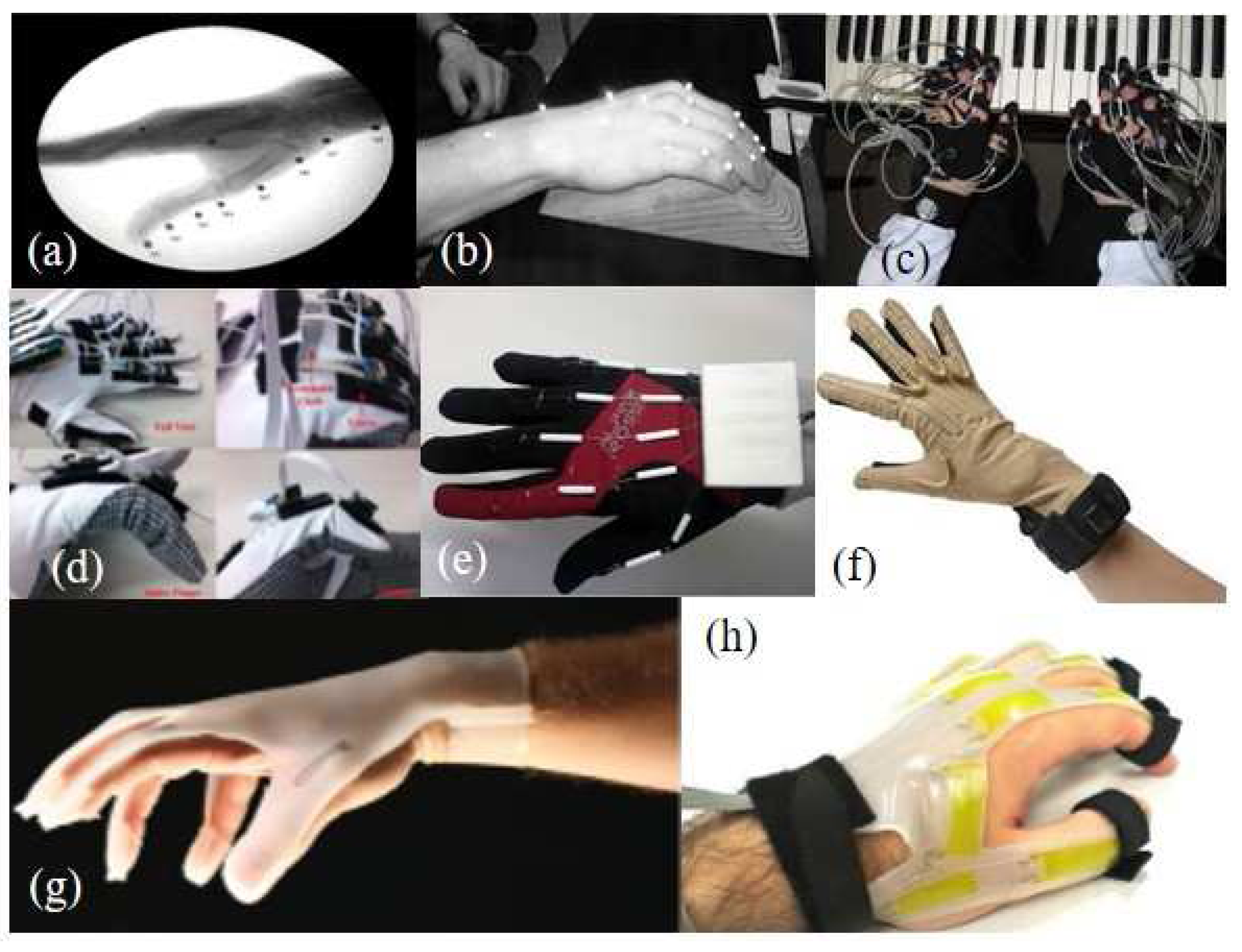
:1. Introduction
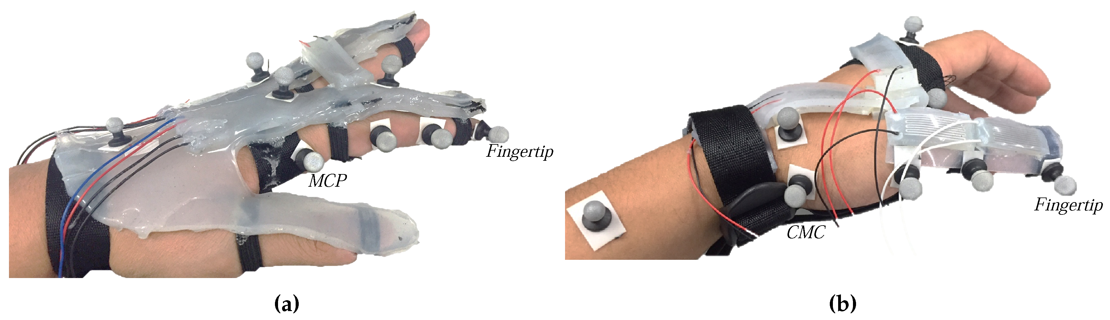
2. Configuration of the Soft Sensor-Based 3D Finger Motion Measurement System
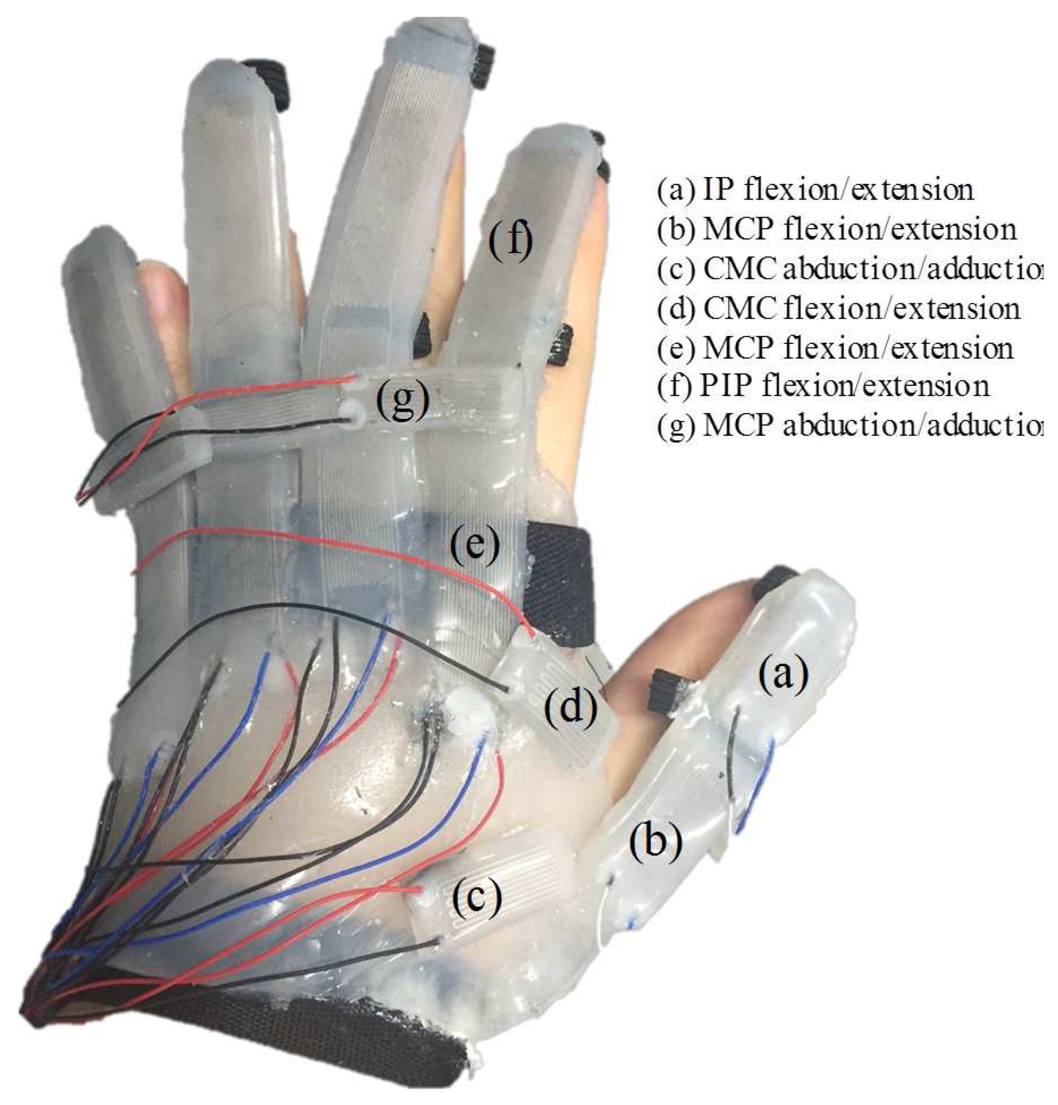
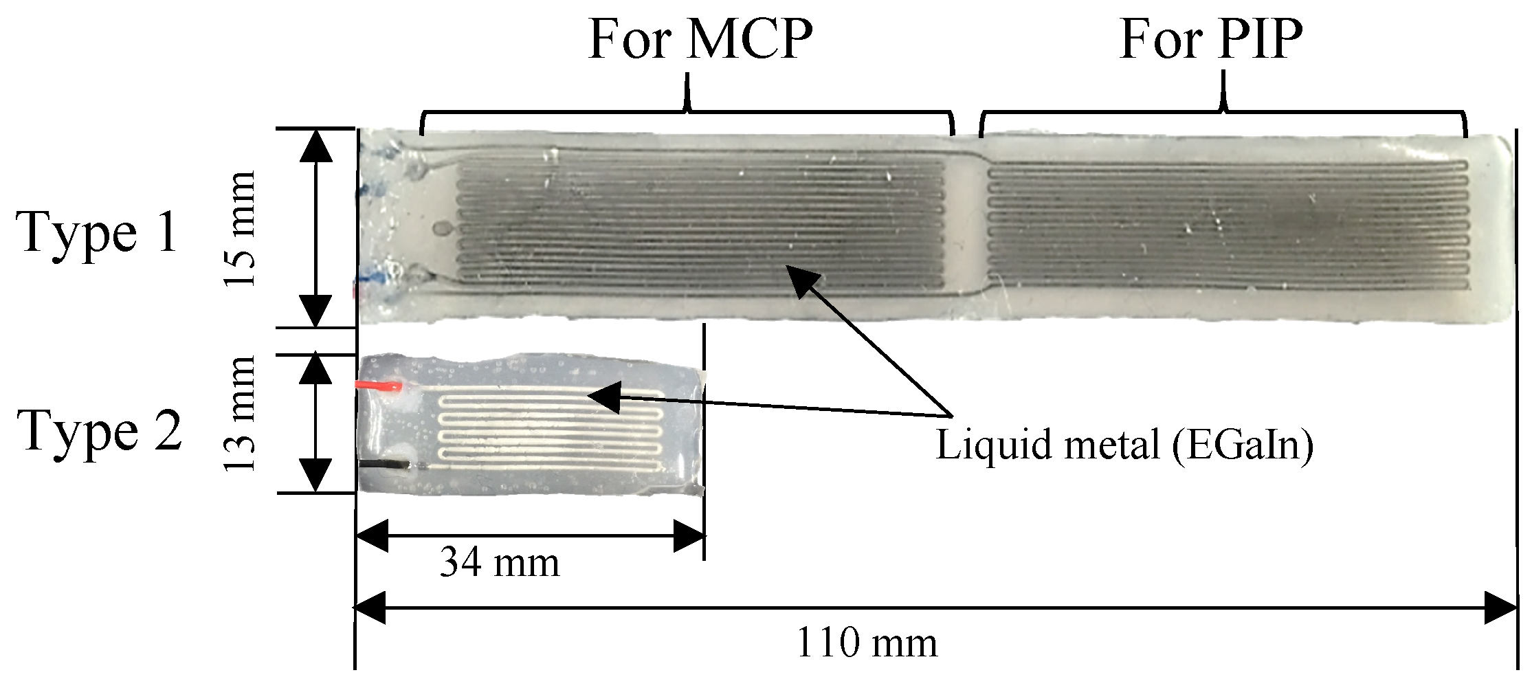
2.1. Design of the Soft Sensors
2.2. Fabrication
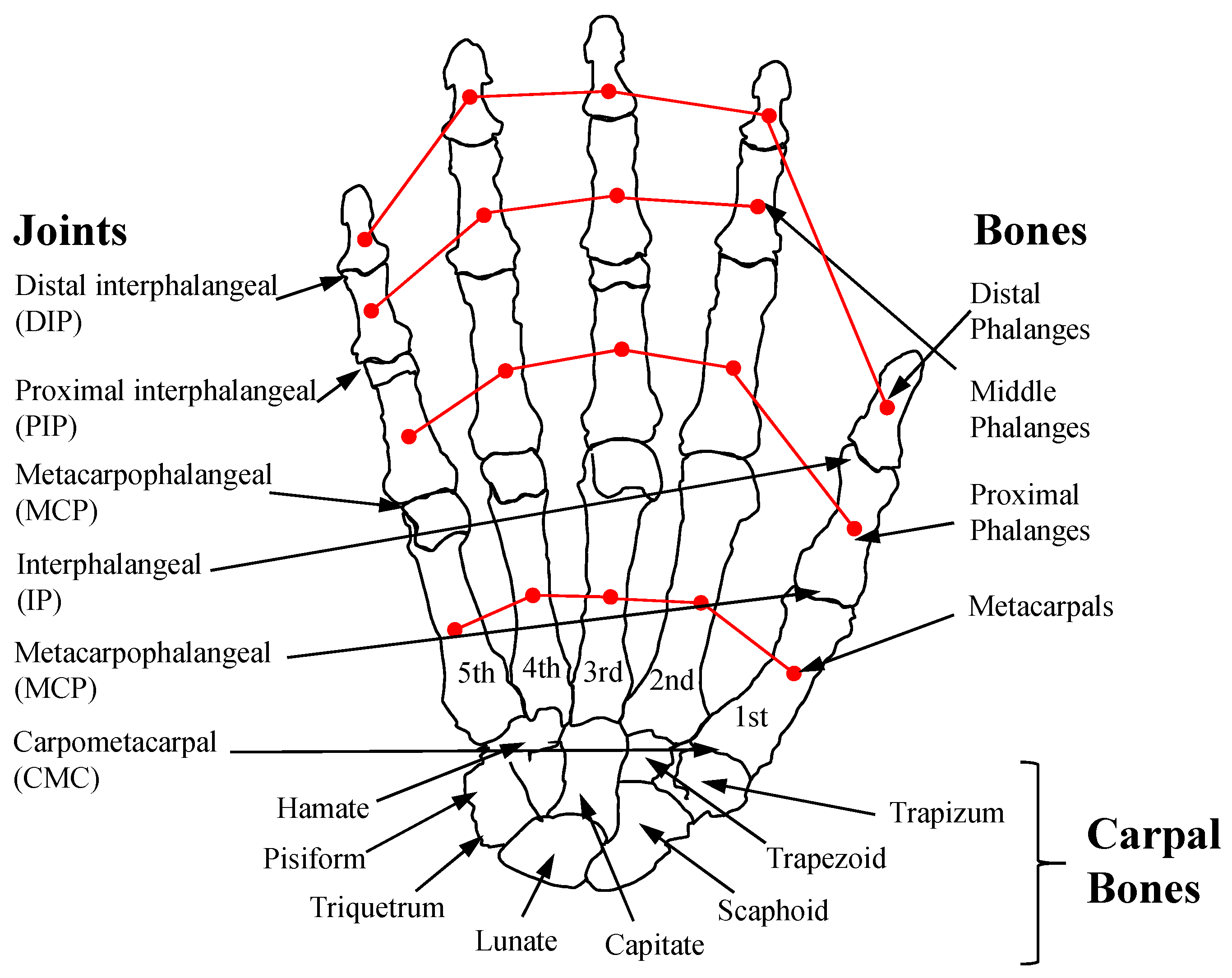
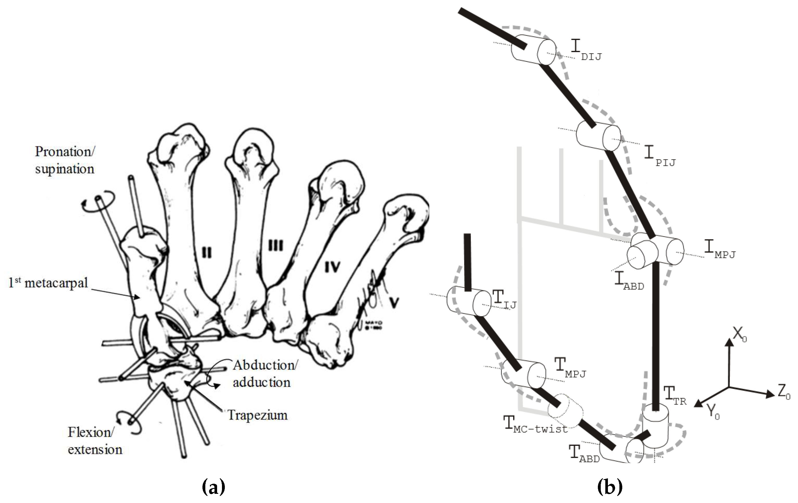
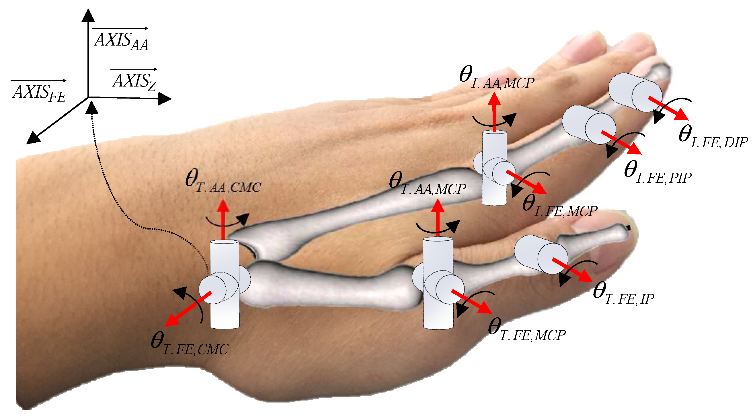
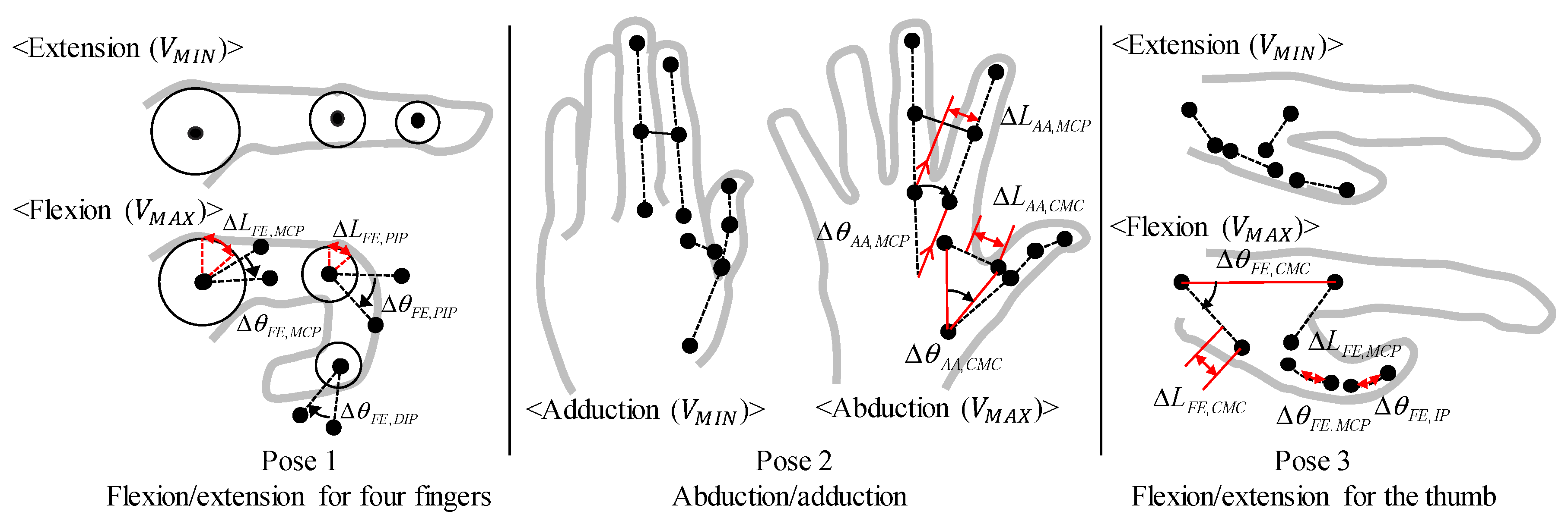
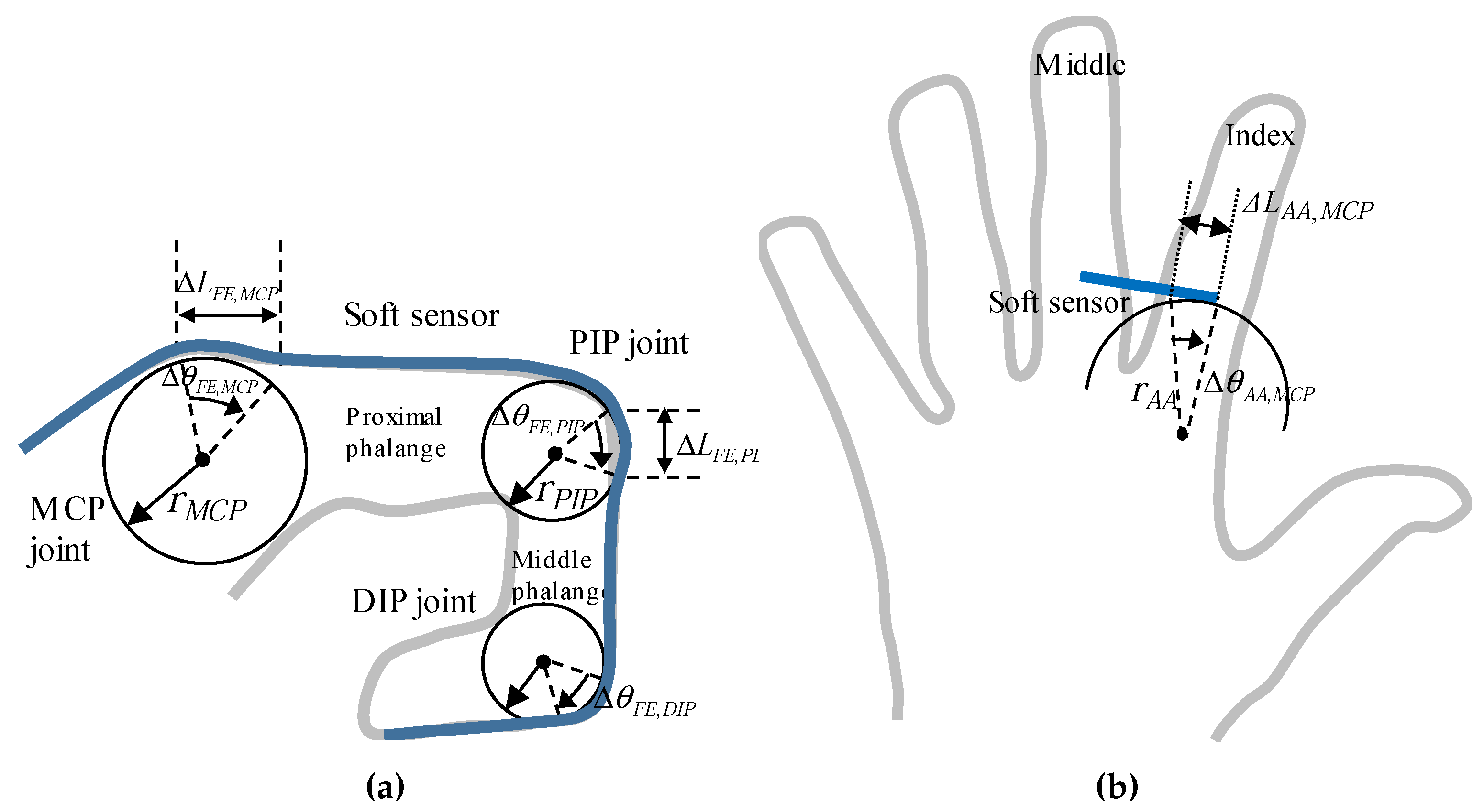
3. Modeling of Finger Joints
3.1. Modeling of Four Fingers
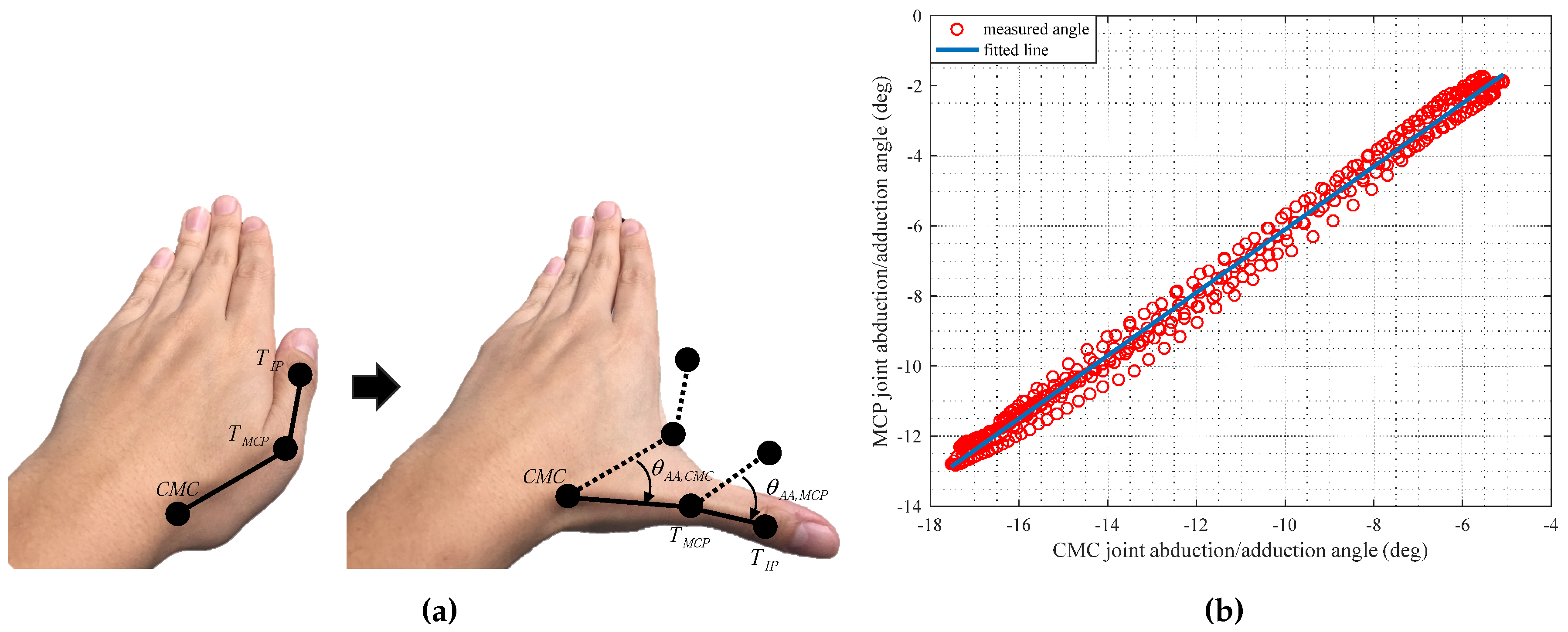
3.2. Modeling of the Thumb
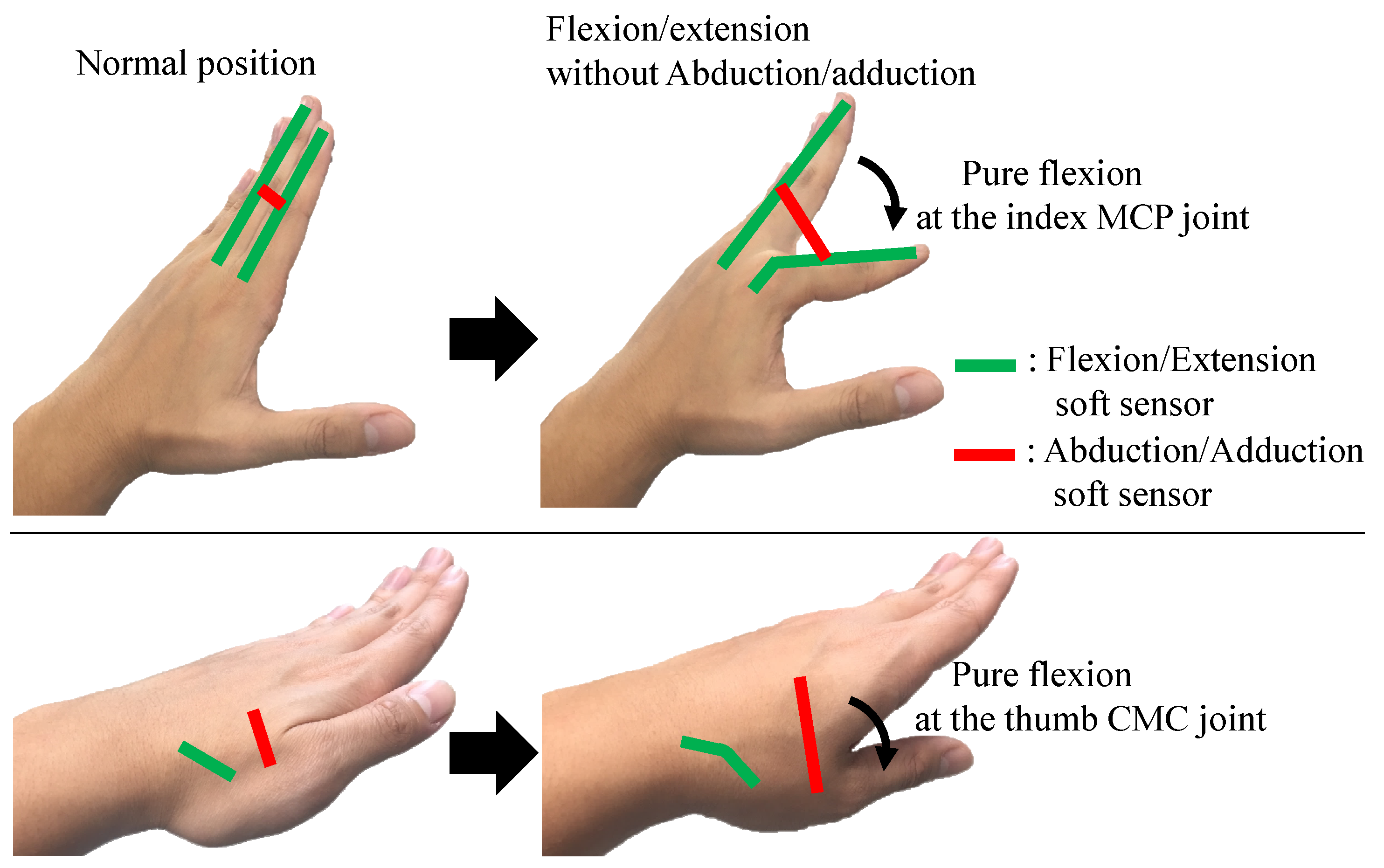
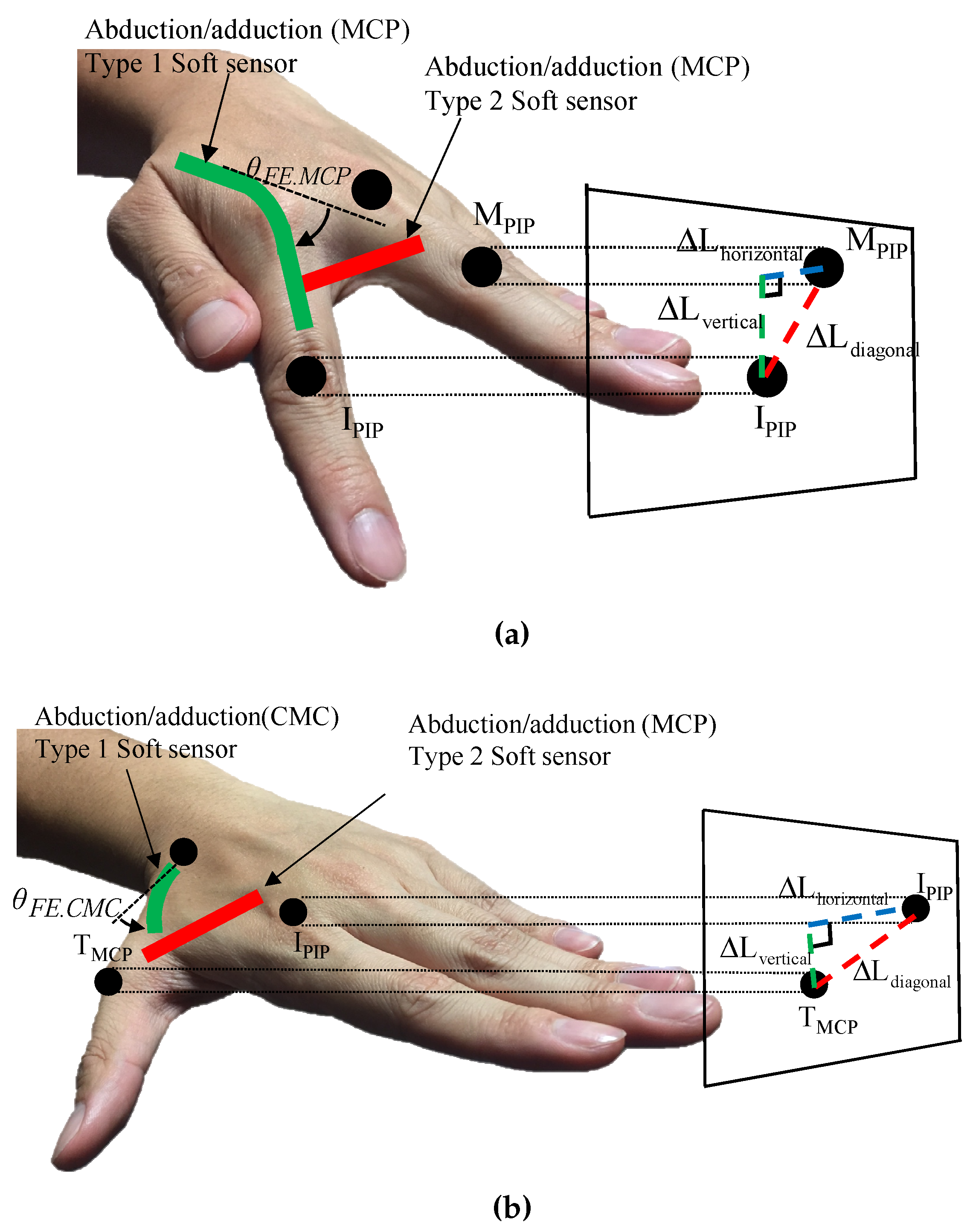
4. Decoupling Algorithms for the Soft Sensor Signals
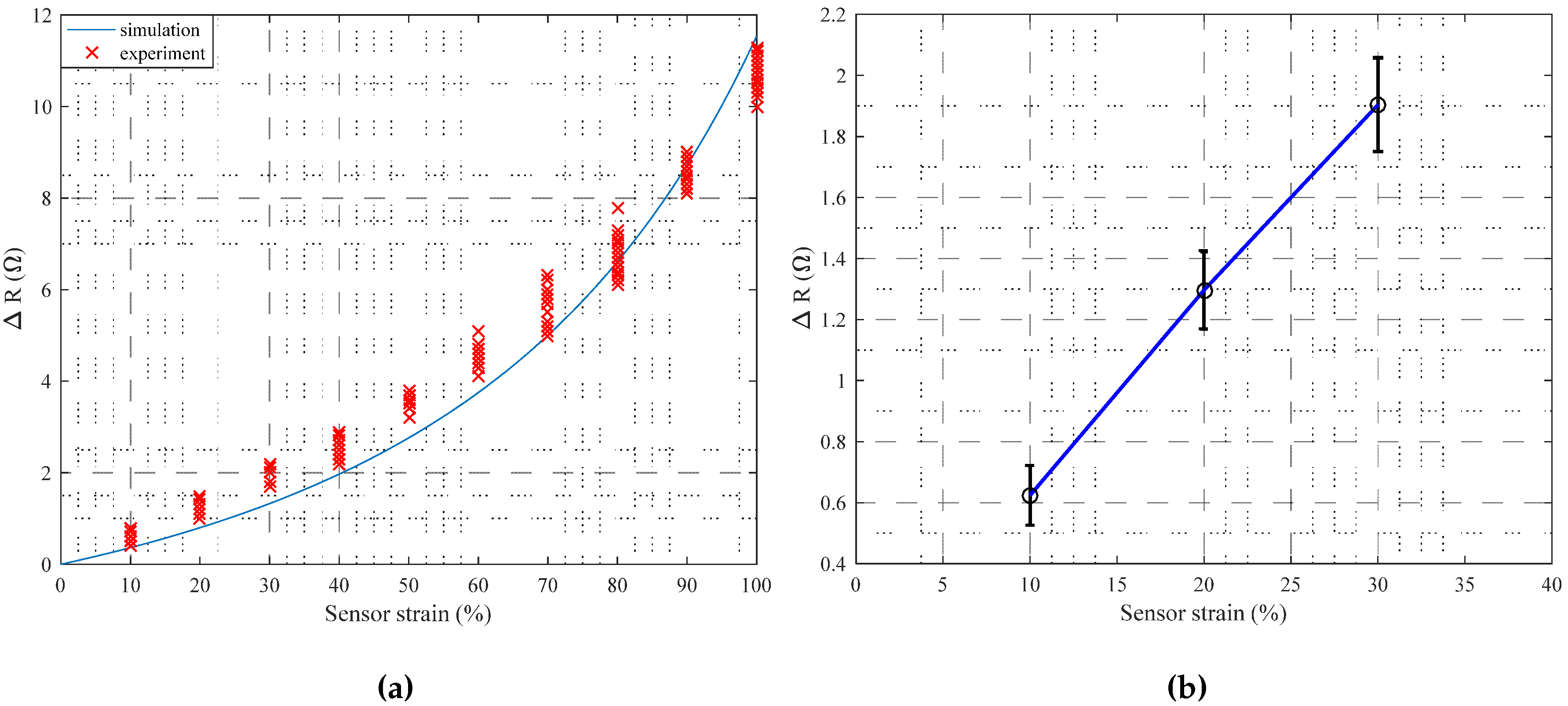
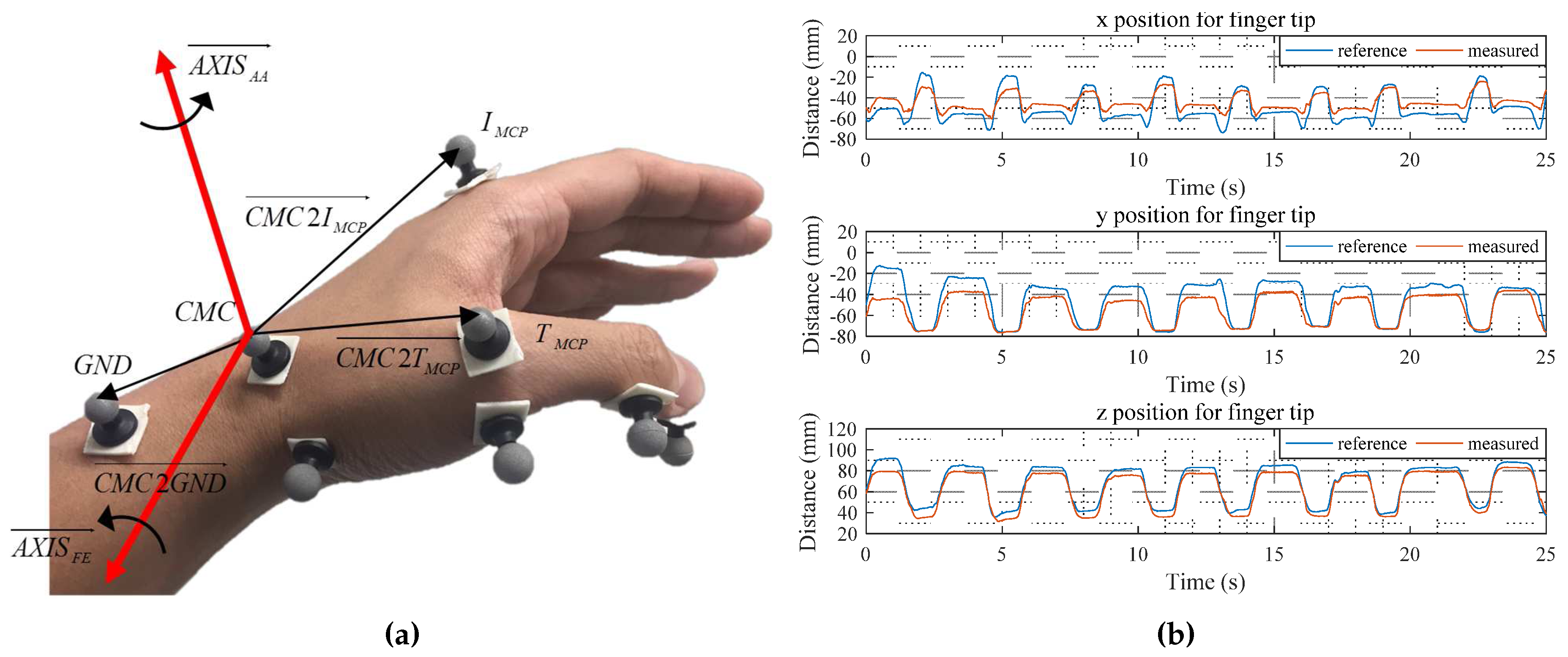
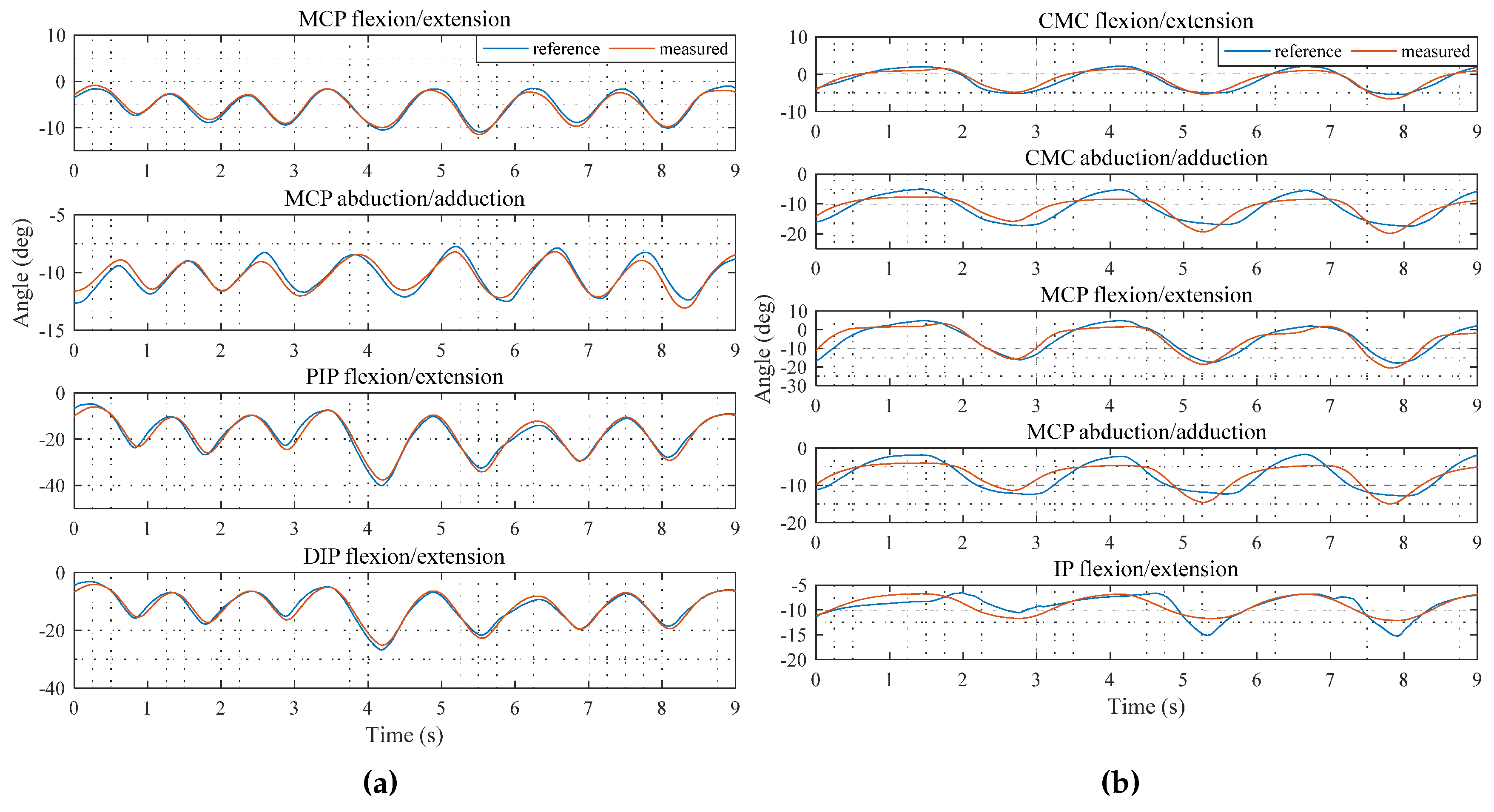
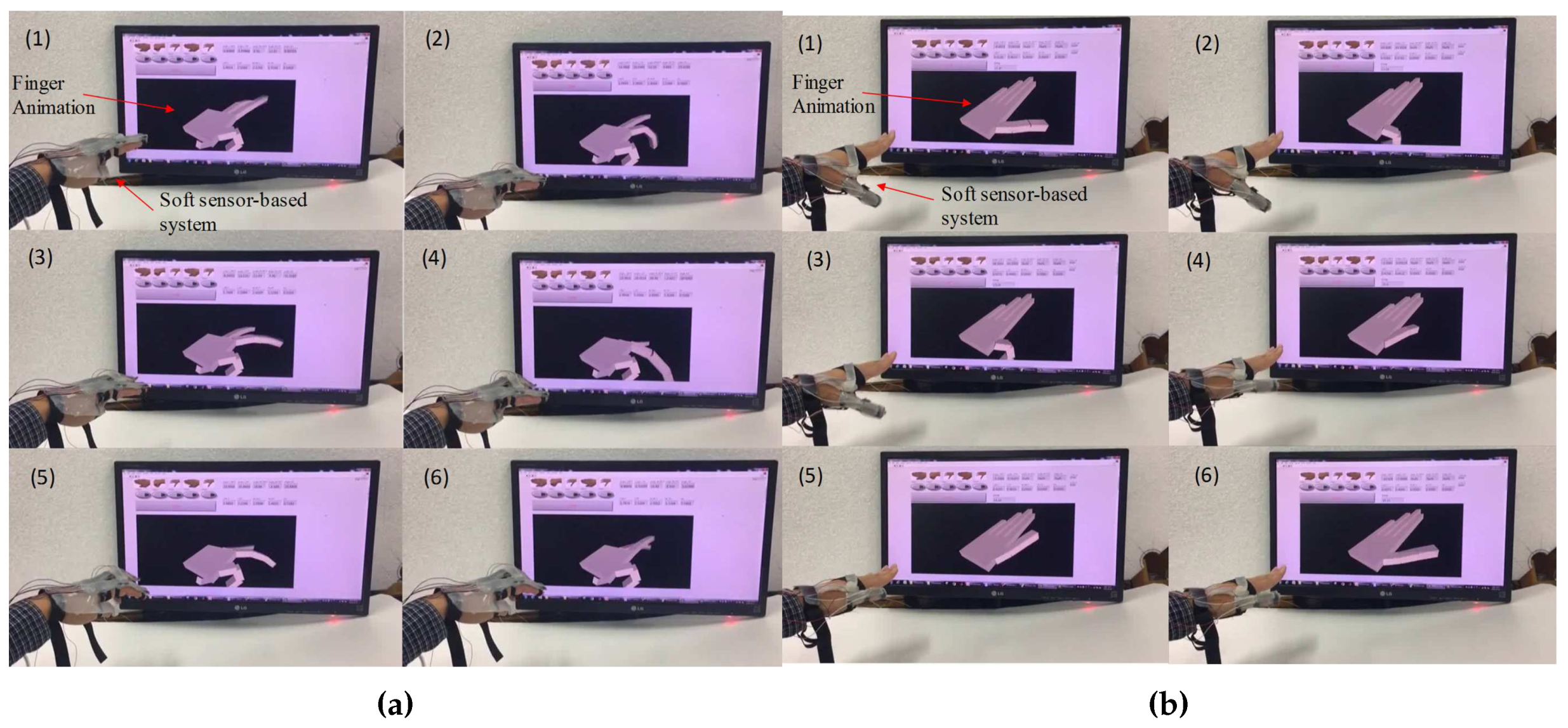
5. Experimental Verification
6. Conclusions
Acknowledgments
Author Contributions
Conflicts of Interest
References
- Rijpkema, H.; Girard, M. Computer animation of knowledgebased human grasping. Comput. Graph. 2002, 25, 339–348. [Google Scholar] [CrossRef]
- Kuo, L.-C.; Su, F.-C. Feasibility of using a video-based motion analysis system for measuring thumb kinematics. J. Biomech. 2002, 35, 1499–1506. [Google Scholar] [CrossRef]
- Cook, J.R.; Baker, N.A.; Cham, R.; Hale, E.; Redfern, M.S. Measurements of wrist and finnger postures: A comparison of goniometric and motion capture techniques. J. Appl. Biomech. 2007, 23, 70–78. [Google Scholar] [CrossRef] [PubMed]
- Mitobe, K.; Kaiga, T.; Yukawa, T.; Miura, T.; Tamamoto, H.; Rodgers, A.; Yoshimura, N. Development of a motion capture system for a hand using a magnetic three dimensional position sensor. In Proceeding of the ACM SIGGRAPH 2006 Research Posters, Boston, MA, USA, 30 July–3 August 2006; p. 102.
- Li, K.; Chen, I.-M.; Song, H.Y. Design and validation of a multi-finger sensing device based on optical linear encoder. In Proceedings of the IEEE International Conference on Robotics and Automation (ICRA), Anchorage, AK, USA, 3–7 May 2010; pp. 3629–3634.
- Park, Y.; Lee, J.; Bae, J. Development of a wearable sensing glove for measuring the motion of finngers using linear potentiometers and flexible wires. IEEE Trans. Ind. Inform. 2015, 11, 198–206. [Google Scholar] [CrossRef]
- Kessler, G.D.; Hodges, L.F.; Walker, N. Evaluation of the cyberglove as a whole-hand input device. ACM Trans. Comput.-Hum. Interact. 1995, 2, 263–283. [Google Scholar] [CrossRef]
- Muth, J.T.; Vogt, D.M.; Truby, R.T.; Menguc, Y.; Kolesky, D.B.; Wood, R.J.; Lewis, J.A. Embedded 3D Printing of Strain Sensors within Highly Stretchable Elastomers. Adv. Mater. 2014, 26, 6307–6312. [Google Scholar] [CrossRef] [PubMed]
- Chossat, J.-B.; Tao, Y.; Duchaine, V.; Park, Y.-L. Wearable Soft Artificial Skin for Hand Motion Detection with Embedded Microfluidic Strain Sensing. In Proceedings of the IEEE International Conference on Robotics and Automation (ICRA), Seattle, WA, USA, 26–30 May 2015; pp. 2568–2573.
- Park, Y.-L.; Majidi, C.; Kramer, R.; Berard, P.; Wood, R.J. Hyperelastic pressure sensing with a liquid-embedded elastomer. J. Micromech. Microeng. 2010, 20, 125029. [Google Scholar] [CrossRef]
- Chossat, J.-B.; Park, Y.-L. A Soft Strain Sensor Based on Ionic and Metal Liquids. IEEE Sens. J. 2013, 13, 3405–3414. [Google Scholar] [CrossRef]
- Park, Y.L.; Chen, B.R.; Wood, R.J. Design and fabrication of soft artificial skin using embedded microchannels and liquid conductors. IEEE Sens. J. 2012, 12, 2711–2718. [Google Scholar] [CrossRef]
- Dickey, M.D.; Chiechi, R.C.; Larsen, R.J.; Weiss, E.A.; Weitz, D.A. Eutectic Gallium-Indium (EGaIn): A Liquid Metal Alloy forthe Formation of Stable Structures in Microchannelsat Room Temperature. Adv. Funct. Mater. 2008, 18, 1097–1104. [Google Scholar] [CrossRef]
- OptiTrack. Camera-Based Motion Capturing System. 2016. Available online: http://optitrack.com/ (accessed on 13 December 2016).
- Landsmeer, J.M.F. The anatomy of the dorsal aponeurosis of the human finger and its functional significance. Anat. Rec. 1949, 104, 31–44. [Google Scholar] [CrossRef] [PubMed]
- Ecoflex. 2016. Available online: https://www.smooth-on.com/product-line/ecoflex/ (accessed on 13 December 2016).
- Lee, J.; Kunii, T.L. Model-based analysis of hand posture. IEEE Comput. Graph. Appl. 1995, 15, 77–86. [Google Scholar]
- Cooney, W.P.; Lucca, M.J.; Chao, E.Y.S.; Linscheid, R.L. The kinesiology of the thumb trapeziometacarpal joint. J. Bone Jt. Surg. 1981, 63, 1371–1381. [Google Scholar] [CrossRef]
- Cooney, W.P.; Linscheid, R.L.; An, K.N. Opposition of the thumb: An anatomic and biomechanical study of tendon transfers. J. Hand Surg. 1984, 9, 777–786. [Google Scholar] [CrossRef]
- Griffin, W.B.; Findley, R.P.; Turner, M.L.; Cutkosky, M.R. Calibration and mapping of a human hand for dexterous telemanipulation. In Proceedings of the ASME IMECE 2000 Symposium on Haptic Interfaces for Virtual Environments and Teleoperator Systems, Orlando, FL, USA, 5–10 November 2000; pp. 1–8.
- Hollister, A.; Buford, W.L.; Myers, L.M.; Giurintano, D.J.; Novick, A. The axes of rotation of the thumb carpometacarpal joint. J. Orthop. Res. 1992, 10, 454–460. [Google Scholar] [CrossRef] [PubMed]
- Nataraj, R.; Li, Z.-M. Robust Identification of Three-Dimensional Thumb and Index Finger Kinematics with a Minimal Set of Markers. J. Biomech. Eng. 2013, 135, 1027–1037. [Google Scholar] [CrossRef] [PubMed]
- Leitkam, S.T.; Bush, T.R.; Bix, L. Determining functional inger capabilities of healthy adults: Comparing experimental data to a biomechanical model. J. Biomech. Eng. 2014, 136, 021022. [Google Scholar] [CrossRef] [PubMed]
- Jacopo, A.; Caselli, S. Grasp Recognition in Virtual Reality for Robot Pregrasp Planning by Demonstration. In Proceedings of the IEEE International Conference on Robotics and Automation, Orlando, FL, USA, 15–19 May 2006; ISO 690. pp. 2801–2806.
- Linear Technology, LT1637. Available online: https://www.linear.com (accessed on 25 January 2017).
- National Instruments, NI PCIe-6353. Available online: https://www.ni.com (accessed on 25 January 2017).
- Dowling, N.E. Mechanical Behavior of Materials; Pearson: Upper Saddle River, NJ, USA, 1999. [Google Scholar]


| Type 1 Sensor | Type 2 Sensor | |
|---|---|---|
| Sensor length [mm] | 110 | 34 |
| Sensor height [mm] | 2 | 12 |
| Sensor width [mm] | 15 | 8 |
| Channel length [mm] | 810 (for the MCP)/930 (for the PIP) | 395 |
| Channel height [mm] | 0.3 | 0.5 |
| Channel width [mm] | 0.3 | 0.5 |
© 2017 by the authors. Licensee MDPI, Basel, Switzerland. This article is an open access article distributed under the terms and conditions of the Creative Commons Attribution (CC BY) license ( http://creativecommons.org/licenses/by/4.0/).
Share and Cite
Park, W.; Ro, K.; Kim, S.; Bae, J. A Soft Sensor-Based Three-Dimensional (3-D) Finger Motion Measurement System. Sensors 2017, 17, 420. https://doi.org/10.3390/s17020420
Park W, Ro K, Kim S, Bae J. A Soft Sensor-Based Three-Dimensional (3-D) Finger Motion Measurement System. Sensors. 2017; 17(2):420. https://doi.org/10.3390/s17020420
Chicago/Turabian StylePark, Wookeun, Kyongkwan Ro, Suin Kim, and Joonbum Bae. 2017. "A Soft Sensor-Based Three-Dimensional (3-D) Finger Motion Measurement System" Sensors 17, no. 2: 420. https://doi.org/10.3390/s17020420