1. Introduction
The skin is one of the main organs of the human body; it helps us to interact with our surroundings through implementing many different and relevant functions, e.g., protection of the inner body organs, detection of cutaneous stimuli, etc. The skin represents the human physical barrier, allowing us to perceive various shapes and textures, changes in temperature, and varying degrees of contact pressure. To achieve high sensing capabilities, several different types of highly-specialized sense receptors are embedded within our skin. These receptors first transduce information generated by mechanical stimuli into electrical signals and then transmit them to the central nervous systems for more complex processing. The collected signals are eventually interpreted by the somatosensory cortex, [
1] permitting us to perceive the sense of touch and to easily interact with our physical world.
The development of electronic skin (e-skin) is a very complex and challenging goal which involves many different and complementary research areas. Nonetheless, the effort to create an e-skin with human-like sensory capabilities is motivated by the possibility of being highly applicable for autonomous artificial intelligence (e.g., robots), biomedical instrumentation, and replacement prosthetic devices capable of providing the same level of sensory perception of the organic equivalent.
Following the definition given by Dahiya et al. [
2], tactile sensing involves the detection and measurement of contact parameters in a predetermined contact area and subsequent processing of the signals to extract structured and meaningful information which is subsequently transmitted to higher system levels for perceptual interpretation.
Figure 1 provides a structural block diagram of an e-skin system. The development of the e-skin system starts by defining the system specifications, designing and fabricating the mechanical arrangement of the skin itself (i.e., sensing materials), together with the embedded digital system for tactile data processing. The different e-skin tasks are still in their infancy and far from being properly addressed even if many research groups are addressing the topic with different approaches at each level of the problem [
3,
4,
5,
6,
7,
8,
9].
Significant progress in the development of e-skin has been achieved in recent years by the concentration on mimicking the mechanically compliant highly sensitive properties of human skin. For the sensing materials, stretchable electrodes for e-skin have been developed in [
10], and the transformation of a typically brittle material, Si, into flexible, high-performance electronics by using ultrathin (100 nm) films connected by stretchable interconnects is presented in [
11]. Someya et al. have fabricated flexible pentacene-based organic field-effect transistors (OFETs) for large-area integrated pressure-sensitive sheets with an active matrix readout [
12]. For the system implementation, however, the design of a tactile sensor patch to cover large areas of robots and machines that interact with human beings is reported in [
13]. The realizations are mostly custom-built and the sensor is implemented with commercial force sensors. This has the benefit of a more foreseeable response of the sensor if its behavior is understood as the aggregation of readings from all of the individual force sensors in the array. Mittendorfer et al. [
14] introduced a cheap, scalable, discrete force cell and integrated it, along with other (discrete) sensor devices, into a multi-modal artificial skin, based on hexagonal-shaped, intelligent unit cells (i.e., PCBs). However, the very large amount of data, the complexity of data processing algorithms, and the relevant amount of energy and area restrict the current implementations of e-skin systems to networked PCB systems.
This paper presents the architecture of an electronic skin system designed to be hosted on embedded devices. The overall system includes both the e-skin layer and the underlying pattern-recognition module, which is entitled to support smart tactile-sensing functions. In the proposed system, pattern recognition is implemented by exploiting machine-learning (ML) methodologies, which have already been proved able to tackle complex touch-recognition tasks [
15,
16,
17,
18,
19,
20]. In particular, the present pattern-recognition device takes advantage of an approach that can deal with the inherent tensor morphology of raw tactile data [
18]. The proposed architecture demonstrates the feasibility of the approach despite the hardware complexity when real-time functionality is aimed. Moreover, the paper highlights the high amount of power consumption needed for the input touch modalities classification task and proposes possible solutions for effective implementation of e-skin systems.
The rest of the paper is organized as follows:
Section 2 describes the e-skin from a systems perspective, defining the different structural components for the system development.
Section 3 introduces the pattern recognition model exploiting machine learning methodologies. The section describes a tensor-based framework for tactile data.
Section 4 presents the digital signal processing computational architecture for the tensorial approach. It analyzes the computational load of the proposed approach and provides the hardware implementation results based on FPGA device. A classification study based on hardware implementation results is elaborated in
Section 5, and finally conclusions and future perspectives are reported in
Section 6.
3. The Pattern Recognition Model
Machine-learning techniques can support the design of predictive systems that make reliable decisions on unseen input samples [
27,
28]. This ability is attractive whenever the underlying phenomenon to be modelled is complex; i.e., when an explicit formalization of the input-output relationship is difficult to attain. Actually, ML can model the input-output function by a “learning from examples” approach. Eventual implementations can vary according to different application scenarios, but all share a common probabilistic setting.
In the case of a tactile-sensing framework, the problem is to interpret the sensor signals to discriminate between a set of stimuli that the system is expected to recognize. ML techniques may indeed face challenging assignments such as the discrimination of materials or the interpretation of touch modalities. To this purpose, one can reduce the overall complexity of the pattern recognition problem by splitting the modelling process into two tasks:
The definition of a suitable descriptive basis for the input signal provided by the sensor (or lattice of sensors), i.e., a feature-based description that lies in a feature space
:
In Equation (1),
S is the third-order tensor that characterizes sensor outputs.
The empirical learning of a model for the non-linear function,
ξ, that maps the feature space,
, into the set of tactile stimuli of interest:
In this research, T includes a finite number of stimuli, hence,
ξ implies a multi-class classification task.
The literature provides a wide range of ML-based techniques to set up ξ. On the other hand, the peculiarities of a tactile-sensing framework notably shrink the range of solutions that best fit the underlying three-dimensional tensor problem. In fact, the large majority of ML paradigms is designed to support framework that processes n-dimensional vectors that lie in some feature space . This, in turn, means that one would need a feature-extraction process that significantly alters the original structure of the signal provided by the sensor, since .
In this paper, the setup of
ξ is supported by a theoretical approach that can lead to a tensor-oriented kernel machine. That is, the function
ξ is learned by using a support vector machine (SVM) [
27] that can inherently process tensors, rather than
n-dimensional vectors. Accordingly, the pattern-recognition module can benefit from (1) a powerful machine-learning paradigm (SVM); and (2) a suitable processing of sensors data.
3.1. SVM
The empirical learning of the mapping function ξ stems from a training procedure that uses a dataset, X, holding Np patterns (samples). In a binary classification problem, each pattern includes a data vector, , and its category label y {−1, 1}. When developing data-driven classifiers, the learning phase requires both x and y to build up a decision rule. After training, the system processes data that do not belong to the training set and ascribes each test sample to a predicted category .
According to the SVM model, the function that predicts the class of a sample is a sharp decision function,
, where
f(
x) is a weighted sum of some nonlinear “kernel” basis functions. A kernel function
K(
xi,
xj) allows to handle only inner products between pattern pairs, disregarding the specific mappings of individual patterns [
27]. The kernel trick allows setting up the non-linear variant of virtually any algorithm that can be formalized in terms of dot products.
Actually, one has:
where the number of support vectors
Nsv , the “bias” term
b, and coefficients α
i are computed by the training algorithm [
27], which minimizes a quadratic cost function [
27]. The eventual generalization performance of a SVM depends also on the specific setting of the scalar parameter
C that regulates the trade-off between accuracy and complexity in the training process [
27].
3.2. A Kernel Function for Tensors
The theoretical framework presented in [
29] introduced a kernel function for developing tensor-based models. Such a result is noteworthy in that it allows every kernel machine to deal with tensors. This goal is achieved by designing a suitable kernel that can exploit the algebraic structure of tensors. As a major consequence, one can rewrite Equation (3) by making use of a kernel
, where
are tensors rather than n-dimensional vectors.
In [
29], the kernel function
that processes two generic tensors
is formulated as:
where:
In Equation (6),
is the matrix computed by applying singular value decomposition (SVD) to
, which corresponds to the mode-
n unfolding of
. First, the SVD remaps the original matrix
into a coordinate system where the covariance matrix is diagonal. Thus:
where
is a (
I1I2…IN−1IN+1…IN) × (
I1I2…IN−1IN+1…IN) orthogonal matrix. Then,
is obtained by selecting the first
r columns of
, with
r = rank(
). A similar procedure applies to
.
Overall, the computation of
requires a set of 2
N SVD’s (as both
and
are processed). Then, two matrix products for each
must be performed. The implementation of the kernel-based decision function, Equation (4), requires a set of
Nsv inner products
K(∙,∙), involving the test pattern versus all training patterns. On one hand, the SVD result of each training pattern is computed offline and is stored in memory; however, the SVD of the test pattern has to be worked out online. Thus, the computational cost
OPRED associated to such step is:
where
OSVD and
OMP are the computational costs of a SVD and a matrix product, respectively.
3.3. A Tensor-Based Framework for Tactile Data
The paper of Gastaldo et al. [
18] showed that a pattern recognition framework based on the tensorial SVM can effectively tackle touch modality classification. The corresponding machine learning system models the mapping function
ξ by using a dataset holding
Np patterns (samples), where each pattern now includes a data tensor
and its category label
y {−1, 1}. This allows keeping the original training procedures adopted by the SVM model. As a result, Equations (1) and (2) can be reformulated as follows:
where
is a tensor space. The process
φ(9) now can work out a tensor-based description from
S, thus preserving the structure of the signal originally provided by the tactile sensor. In principle, the learning system, Equation (4), could be designed to receive as input the tensor
S directly. In fact, pre-processing may be needed to better characterize the underlying tactile phenomenon. In [
18], two different pre-processing approaches have been suggested.
The experimental results provided in [
18] proved that “tensor-SVM” could obtain consistent performances on a three-class classification problem. The experimental evidence seemed to confirm that the availability of a tensorial kernel function may prove valuable when tackling classification problems that admit a natural multiway representation.
4. Digital Signal Processing Implementation
The implementation of real-time embedded electronic system based on the tensorial framework described in
Section 3.3 is targeted for the DSP of the electronic skin system.
As shown in the block diagram of the
Figure 2, the input of the digital signal processing block is 3000 matrices (8 × 8)/s which represents a data arrangement in terms of a time stream of arrays, i.e., as a third-order tensor £(8 × 8 × 3000), where the first two dimensions are defined by the geometry of the sensor array (8 × 8), while the time defines the third tensor dimension. The high amount of data contained in the tensor £(8 × 8 × 3000) is reduced according to the method proposed in [
18] in order to reduce the complexity of computation. Applying this method to the input tensor results a reduced tensor
φ(8 × 8 × 20).
Figure 3 shows a sketch of the different computation steps needed to classify input touch modalities using the tensorial approach. The approach is applied following two phases: offline learning and online classification. During the offline learning, the training is done using a dataset holding a number of samples to build up a decision rule and hence developing data-driven classifier. Thus, in the online classification phase, the system computes the distances between the data from the input touch modality and that do belong to the training set; using the offline developed classifier, the system classifies each input sample with a predicted category.
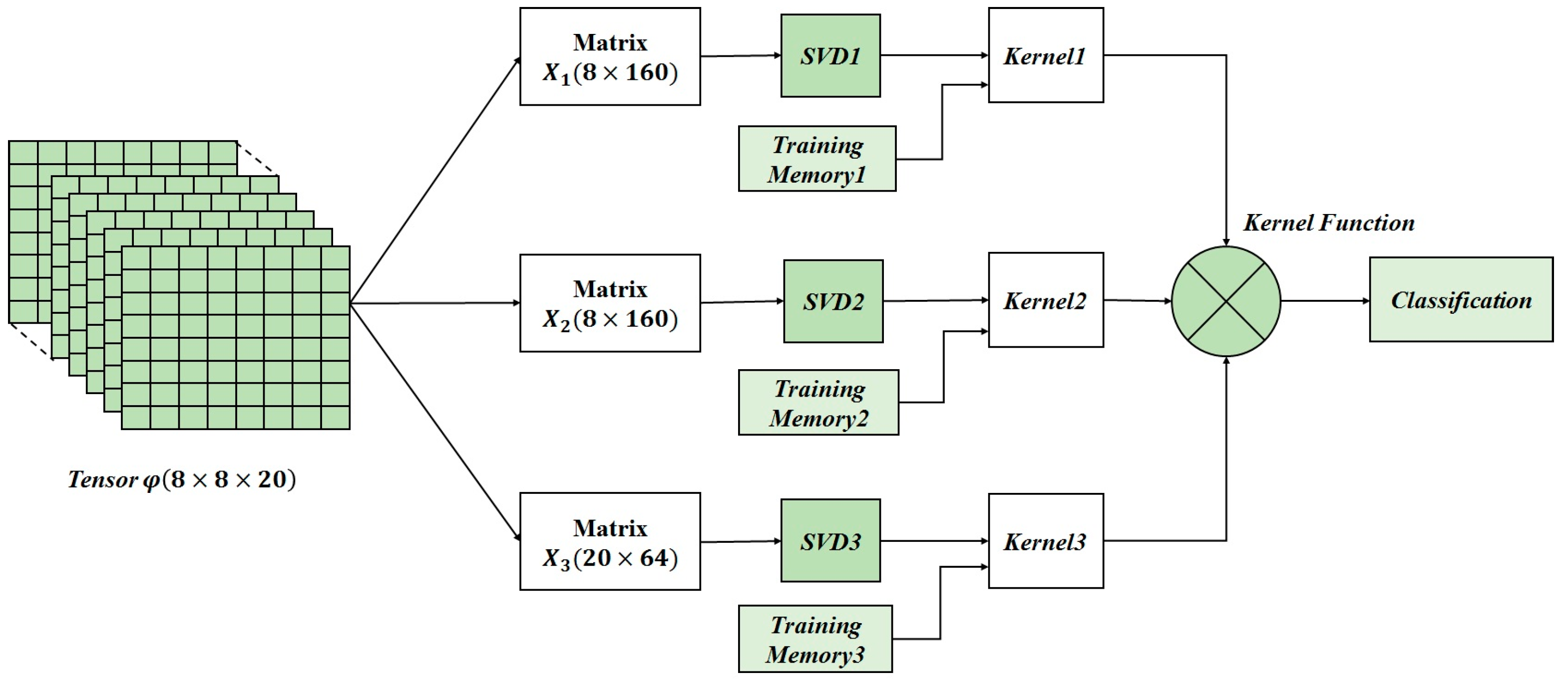
The DSP deals with the online classification phase of the approach. The online computation architecture for hardware implementation is described in
Figure 4. The first computational step consists on tensor unfolding i.e., a matrix representation of
φ(8 × 8 × 20) where all the column (row) vectors are stacked one after the other [
30]. Three matrices (
X1 (8 × 160),
X2 (8 × 160),
X3 (20 × 64)) are obtained by applying unfolding. Then, the SVD blocks compute the singular value decomposition which transforms the unfolded matrices into the product of three matrices, e.g.,
X1 =
U1S1V1T where
U1 is an orthogonal matrix containing the eigenvectors of
X1X1T, and
V1 is an orthogonal matrix containing the eigenvectors of
X1TX1. The S
1 matrix is a diagonal matrix diag(σ
0,…,σ
n−1), where the σ
i are the singular values of
X1 (i.e., the square roots of the eigenvalues), being arranged in descending order.
The kernel computation comes into effect after the SVD completion. Kernel computation deals with the kernel factor, which is computed by using the singular vectors (Vi) of the input tensor and the singular vectors of the training tensors for the different classes memorized from the offline training phase. After that, the kernel function is obtained by multiplying the resulted kernel factors for the three unfolded matrices. Finally, the classification is done using the online computed kernel function and the offline memorized training parameters.
4.1. Computational Load Analysis
In addition to the very large amount of tactile data to be processed in real-time, the computation complexity poses a tough challenge in the development of the embedded electronic system. Computational requirements depend on the overall number operations (mainly arithmetic) that the tensorial kernel approach must perform and on the real-time operation.
In order to assess the computational load, a case study [
23] has been considered: the given task is to classify a touch interaction among
Nc = 3 touch modalities (i.e., paintbrush brushing; finger sliding; washer rolling) in 1 s; here
Nc is the number of classification classes and the number
Nt of the training data is set to 100.
As described in the
Figure 3 the approach consists first of computing the singular value decomposition (SVD) [
31] of the unfolded matrix. The analysis of the computational requirements for the SVD is based on the one-sided Jacobi algorithm which provides high accuracy and convergence in about
K = 5:10 iterations. Following step is the computation of the kernel factor for a couple of SVDs, the first corresponding to the tensor input and the second to the tensor representing a predefined class extracted from the training data.
Table 1 shows the number of operations and flops per second needed to implement the tensorial kernel approach. The power consumption of the resulted total FLOPS number has been estimated according to [
32].
Following estimations presented in
Table 1, about 31 GFLOPS (giga-floating point operations per second) are needed for real-time single touch classification. These requirements for the data processing unit are very challenging: an appropriate data processing unit need to be carefully selected in order to meet the target requirements.
Embedded DSP microprocessors for instance, perform their arithmetic operations via software; this can give the flexibility in design, allowing late design changes. For example, let us consider the very well-known ARM Cortex processor family [
33]: the Cortex-R7 can achieve 6 GFLOPS, which is lower than the target requirements highlighted by
Table 1. Moreover, power consumption is not compatible with the target application requirements.
A possible approach to tackle this issue could be to design dedicated application specific integrated circuit (ASIC) on a standard cell technology; to this end, our approach is to use the field programmable gate array (FPGA) which represents an efficient solution combining the strengths of hardware and software. Moreover, prototyping ASIC designs in FPGAs is an effective and economical method of verification.
4.2. FPGA Implementation Results
The computational load study results the SVD as the most computational expensive algorithm of the tensorial kernel approach: it represents about 70% of the computational complexity of the overall approach [
23]. For this reason, methods and architectures for the hardware implementation of the SVD have to be well studied and assessed in order to select an appropriate architecture suitable for the targeted application. In this perspective, three different hardware implementations for the SVD have been presented and assessed in [
34], and an implementation suitable for embedded real-time processing has been selected.
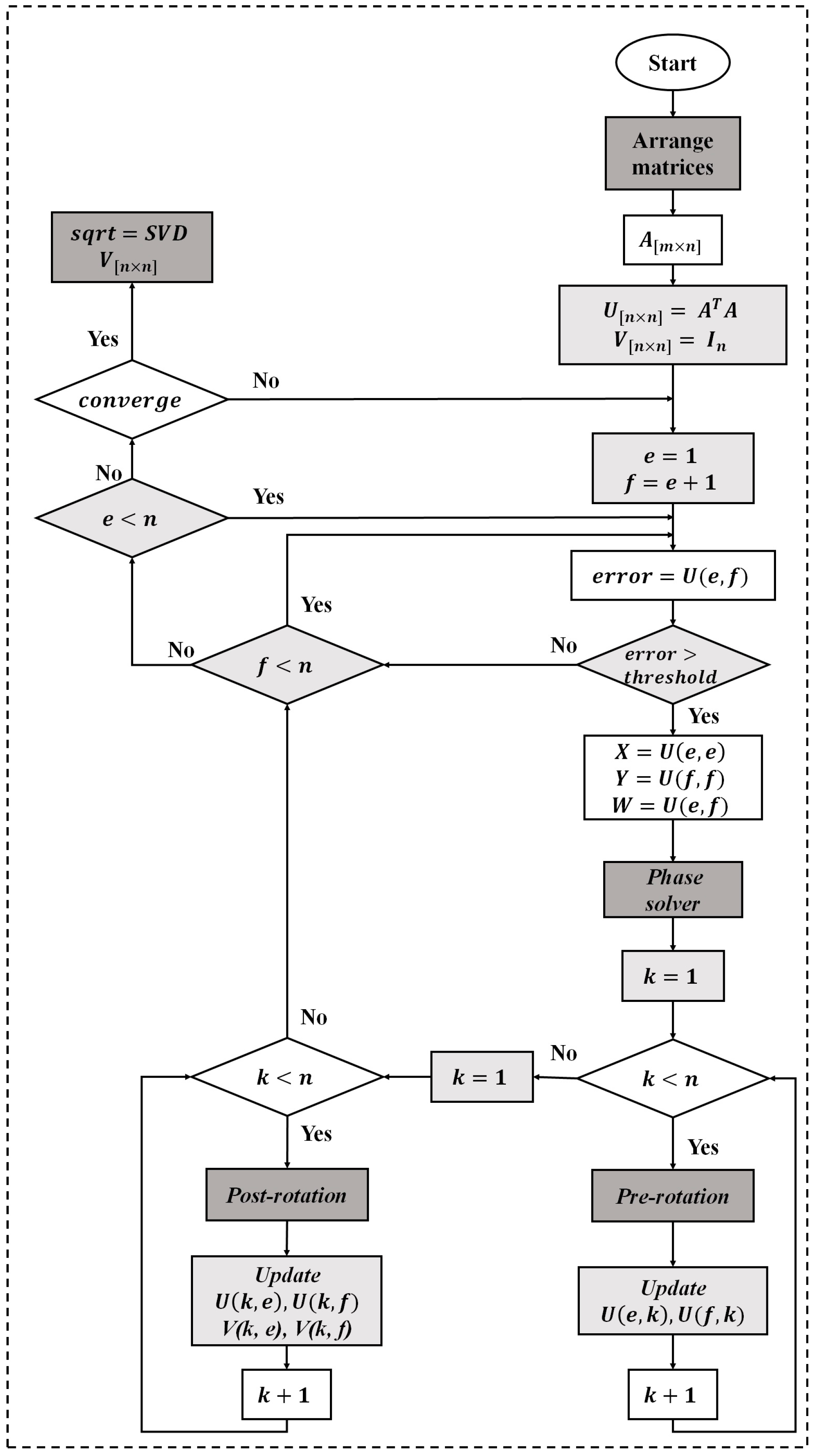
The hardware implementation of the SVD is based on the one-sided Jacobi algorithm as shown in
Figure 4. The one sided Jacobi algorithm is based on diagonalizing rotations preserving angles and lengths by using orthogonal transformations. The algorithm deals with square and symmetric matrices so a matrix symmetrization scheme should be applied at the beginning of the process as shown in
Figure 5. The matrix symmetrization block multiplies the unfolded matrix
Xi by its transpose, resulting a square and symmetrical matrix
Un×n =
XiTXi.
The concept of the one-sided Jacobi algorithm is to apply a sequence of rotations to the symmetric matrix
Ui, in order to reach the diagonal matrix
S. Starting from the
n ×
n symmetric matrix
U =
U0, the algorithm produces a sequence
U1,
U2… which eventually converge to a diagonal matrix with the eigenvalues on the diagonal.
Ui+1 is obtained each time from
Ui by the transformation given by the formula:
where
J(
i,
j,
θ) is called a Jacobi rotation.
The Jacobi rotation J(i, j, θ) is introduced, for an index pair (i, j) and a rotation angle θ, as a square matrix that is equal to the identity matrix I plus four additional entries at the intersections of rows and columns i and j. J(i, j, θ) is calculated on every 2 × 2 matrix to zero out all non-zero off-diagonal elements of the symmetric matrix.
Cyclic Jacobi method [
35] provides an inexpensive computational approach to compute the transformations, it consists in organizing the computations in sweeps within which each matrix element is annihilated once, and each sweep consists of
n(
n − 1)/2 transformations. The one-sided Jacobi computes the SVD through a pre- and post-multiplication by the Jacobi rotation matrix. For that, the complexity of this algorithm lies in the computation of the phase solver block and in the management of the rotations represented by pre- and post-rotation blocks of the
Figure 5. The SVD hardware implementation results based on Virtex-5 XC5VLX330T FPGA device (Xilinx Inc., San Jose, CA, USA) are shown in
Table 2. The architectures and FPGA implementation details of the SVD can be found in [
31].
Using the proposed SVD implementation, the computation of the kernel function according to (5) has been pursued.
Table 3 shows the implementation results of the kernel function using a Virtex-5 XC5VLX330T FPGA device. The results correspond to one kernel function computed for an input tensor compared with an only one training tensor belongs to one class.
6. Conclusions and Future Perspectives
Embedding digital signal processing systems into e-skin for tactile data processing has to comply with severe constraints imposed by the application, e.g., real-time response, low power consumption and small size. In this paper we presented an implementation of DSP-based FPGA for an e-skin system. The DSP deals with machine learning based on a tensorial kernel approach. Implementation results are assessed by highlighting the FPGA resources utilization and power consumption. Results demonstrate the feasibility of the proposed implementation when real-time classification of input touch modalities is targeted.
When considering the pattern-recognition system, a crucial goal will be the development of a multi-class classification framework that can still reliably address such challenging problem when more touch modalities are involved. On the one hand, the proposed approach can be easily extended to multi-class problems. However, such extension has to be carefully addressed when dealing with the hardware implementation.
The implementation results highlight the high amount of power consumption needed which represent the main issue for the system development. Furthermore, scaling up the system requirements (e.g., the number of classes) may dramatically increase the power consumption; a fact that affects the system efficiency. Hence, the requirements related to the development of embedded data processing unit for e-skin are still far from being achieved with the current methods. Methods and techniques to reduce hardware complexity and power consumption of the embedded DSP system should be investigated.
A possible solution would be by using approximate computing which has recently emerged as a promising approach to energy efficient design of digital systems [
36]. Approximate computing relies on the ability of many systems and applications to tolerate some loss of quality or optimality in the computed result. By relaxing the need for fully precise or completely deterministic operations, approximate computing techniques allow substantially improved energy efficiency.
Another possible solution could be by using many-core architectures such as PULP (parallel processing ultra-low power platform) [
39] which have shown promising results on embedded parallel applications, providing state-of-art performance with a reduced power budget. The goal of the PULP platform is to satisfy the computational demands of IoT applications requiring flexible processing of data streams generated by multiple sensors. Such parallel ultra-low-power programmable architecture may allow to meet the computational requirements of the targeted application, without exceeding the power envelope of a few mW typical of miniaturized, battery-powered systems.


