
Sensor-Based Assistive Devices for Visually-Impaired People: Current Status, Challenges, and Future Directions


Abstract
:1. Introduction
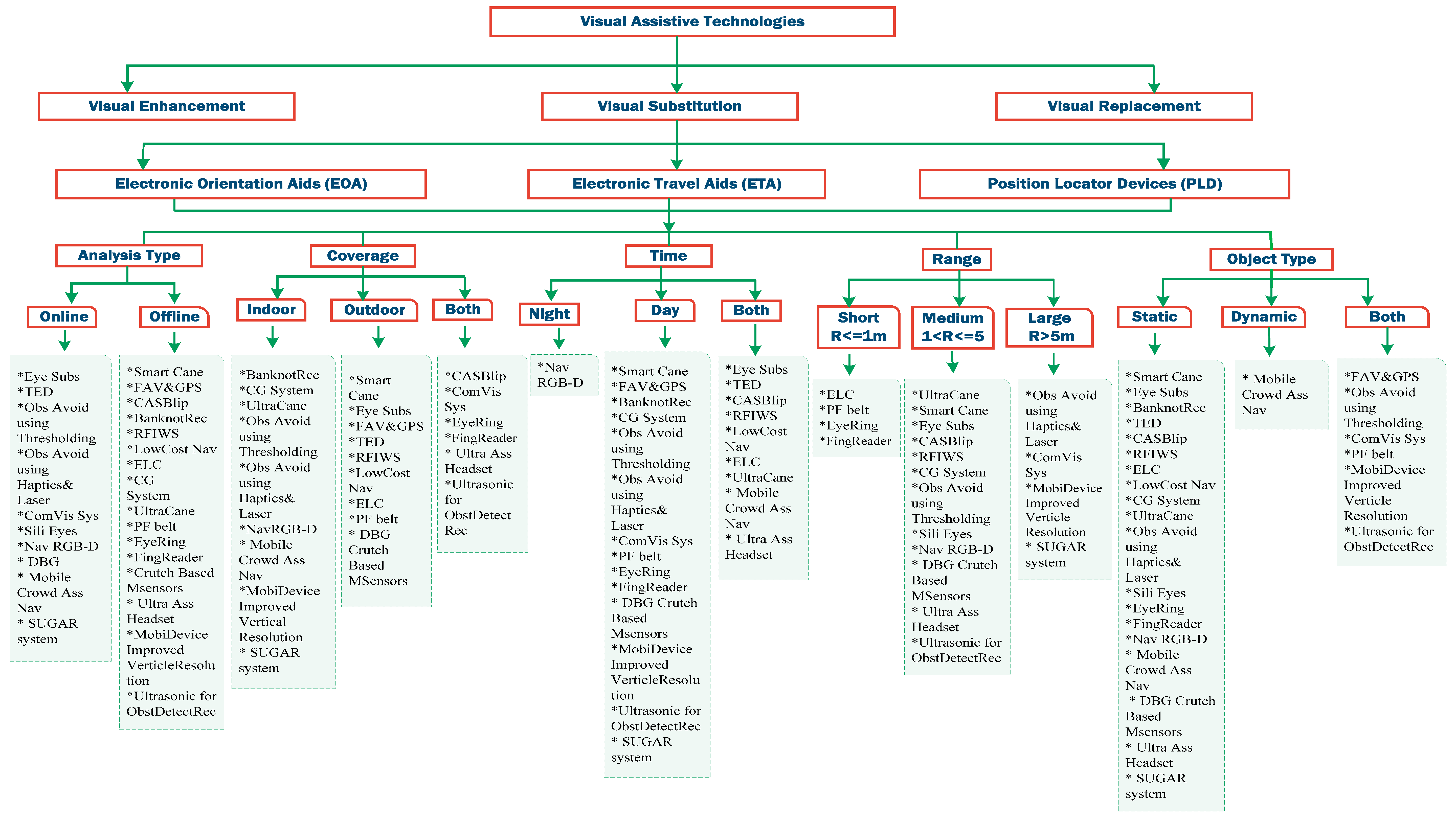
1.1. Assistive Technology
1.1.1. Electronic Travel Aids (ETAs)
- (1)
- Determining obstacles around the user body from the ground to the head;
- (2)
- Affording some instructions to the user about the movement surface consists of gaps or textures;
- (3)
- Finding items surrounding the obstacles;
- (4)
- Providing information about the distance between the user and the obstacle with essential direction instructions;
- (5)
- Proposing notable sight locations in addition to identification instructions;
- (6)
- Affording information to give the ability of self-orientation and mental map of the surroundings.
1.1.2. Electronic Orientation Aids (EOAs)
- (1)
- Defining the route to select the best path;
- (2)
- Tracing the path to approximately calculate the location of the user;
- (3)
- Providing mobility instructions and path signs to guide the user and develop her/his brain about the environment.
1.1.3. Position Locator Devices (PLD)
2. The Most Significant Electronic Devices for Visually-impaired People
3. Analysis
4. Conclusions and Discussion
Author Contributions
Conflicts of Interest
Appendix A

| System Name/Weight/Type of Usage | Type of the Sensors | Accuracy | Analysis Type | Coverage | Measuring Angle | Cost | Limitation | Day/Night | Object Detection Range (Max/Min) | Classification Objects (Dynamic/Static) | Used Techniques for Detection, Recognition or Localization |
|---|---|---|---|---|---|---|---|---|---|---|---|
| Smart Cane Weight: N/A Type of usage: pilot stage | Ultrasonic sensors Water detector | N/A | Real time | Outdoor (only areas have RFID tags) | N/A | High | The water sensor can’t detect the water if it is less than 0.5 deep. The buzzer won’t stop before it is dry. A power supply meter reading needs to be installed to track the status | Day | 1 m–1.5 m | Static | Ultrasonic technology |
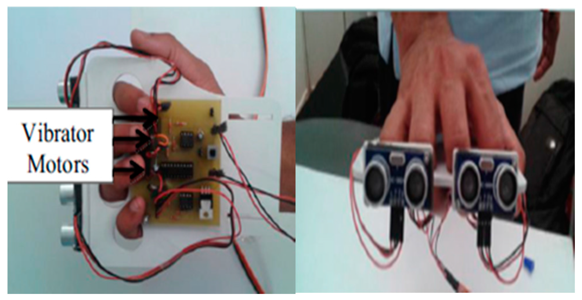
| Eye Substitution Weight: light Type of usage: pilot stage | 2 Ultrasonic Sensors Vibrator motors | N/A | Real time | Outdoor | Each sensor has a cone angle of 15° | $1790 | The design of the system is uncomfortable due to the wood foundation which will be carried by the user most of the time as well as and the figures holes. The team used 3 motors for haptic feedback. They could use a 2-d array of such actuators that can give feedback about more details. Limited use by only Android devices | Day/Night | 2 m–3 m | Static | GPS, GSM, and GPRS Ultrasonic technology |
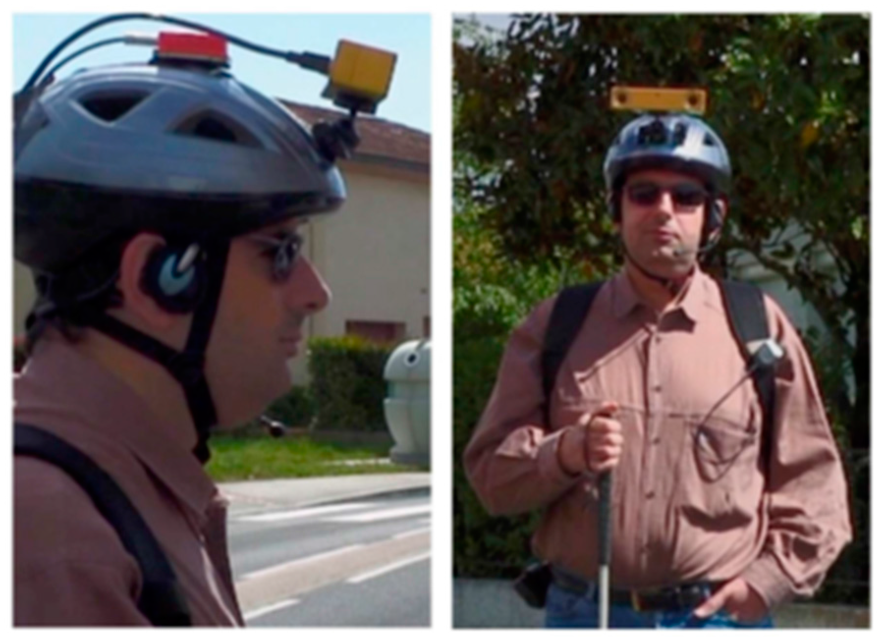
| Fusion of Artificial Vision and GPS Weight: N/A Type of usage: deployment stage | Optical Sensors Bumble bee Stereo Camera 3-axis Accelerometers Electronic compass Pedometer | Accurate results for user position | Real time | Outdoor | 6° of visual angle with (320 × 240 pixel) and 100° field of view with (640 × 480 pixel) | low | The system was tested on the function of the object’s avoidance technique. The system has not been tested or integrated with navigation systems to insure its performance; whether it will enhance the navigation systems as the authors promised or not is unknown. | Day | 2 m–10 m | Static/dynamic | Global Position System (GPS), Modified Geographical Information System (GIS) and vision based positioning SpikNet was used as recognition algorithm |
| Banknote Recognition Weight: N/A Type of usage: pilot stage | iV-CAM | 80% | Real time | N/A | N/A | low | This device was tested only on the Thai banknotes and coins, and it is not capable of working on other currencies that have similar colors of banknotes or similar sizes of coins. The device needs a method that controls the natural light that is used | Day | Closed View | Static | RGB model Banknotes Classification Algorithm |
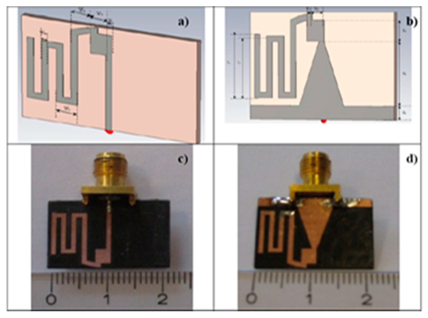
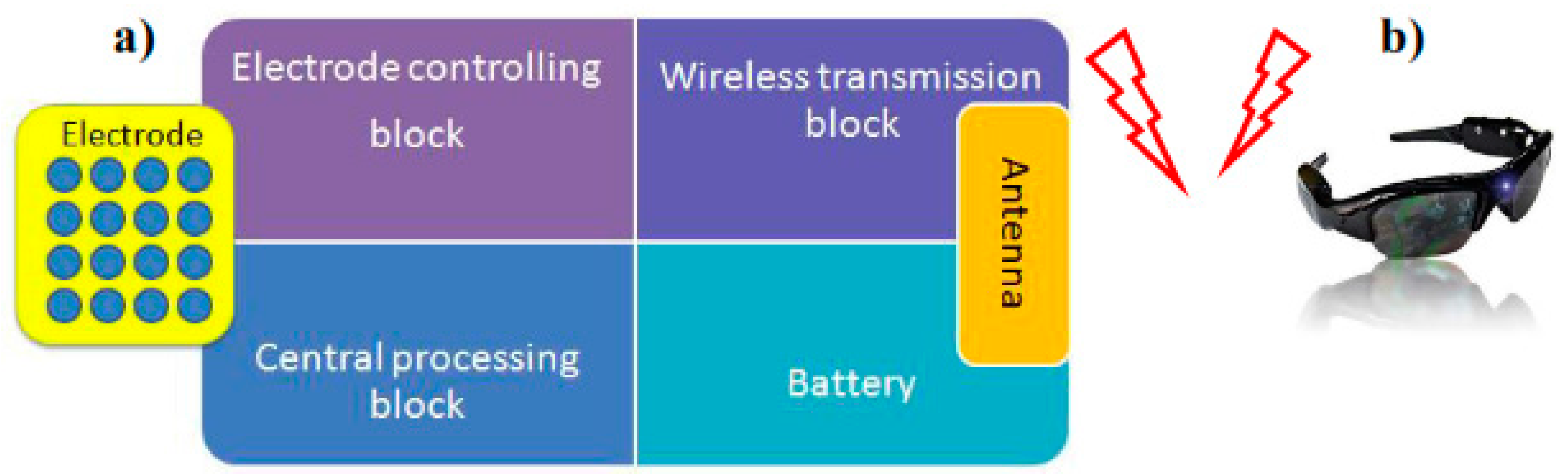
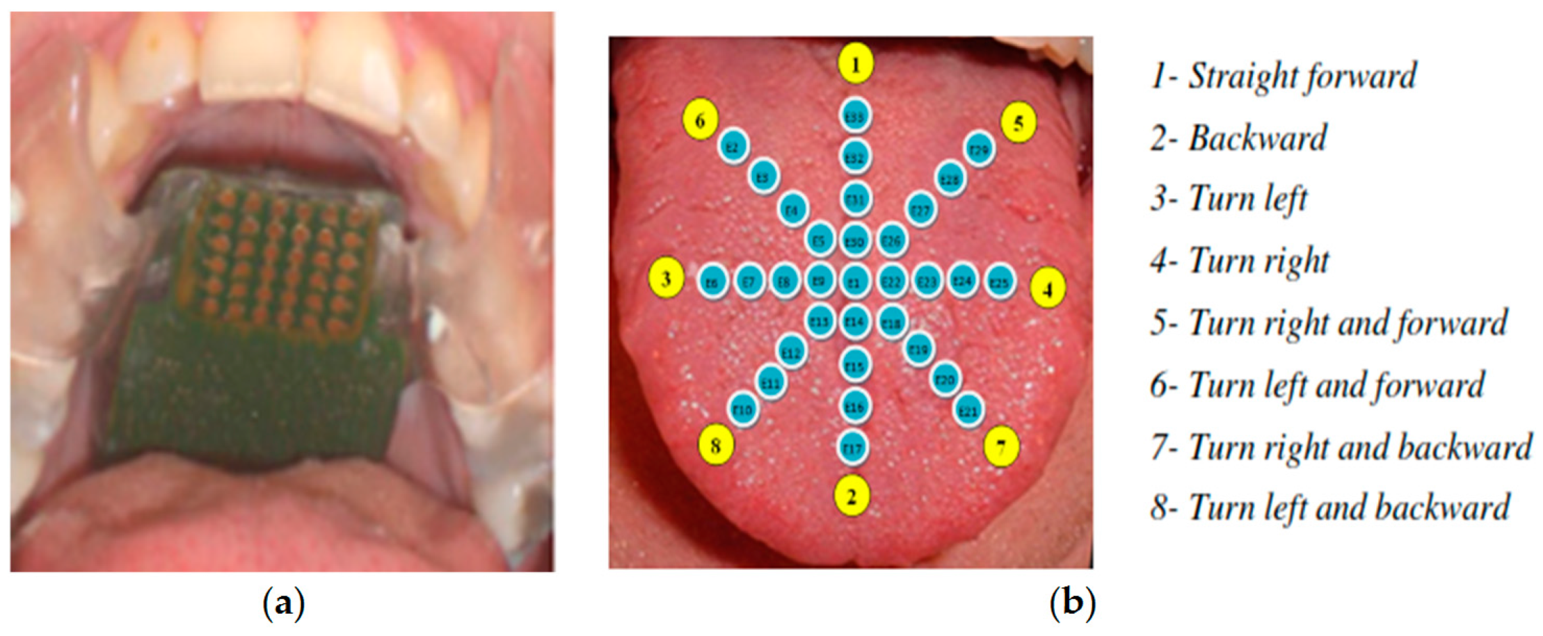
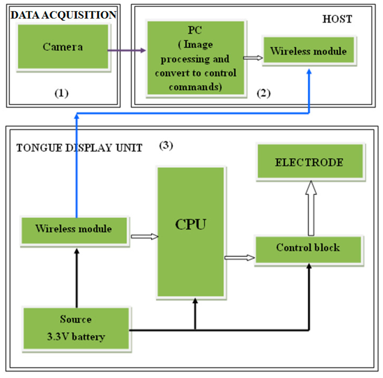
| TED Weight: light Type of usage: pilot stage | Detective Camera | The corresponds are based on the feeling on the dorsal part of the tongue, (1,2,3,4) 100% (7) 10% (5,6,8) 50% | Real time | Outdoor | N/A | low | Antenna is not omni-directional. The range of voltage is not enough to supply the device. It is more difficult to recognize the pulses on the edges of the tongue. | Day/Night | N/A | Static | Tongue–Placed Electro tactile Display |
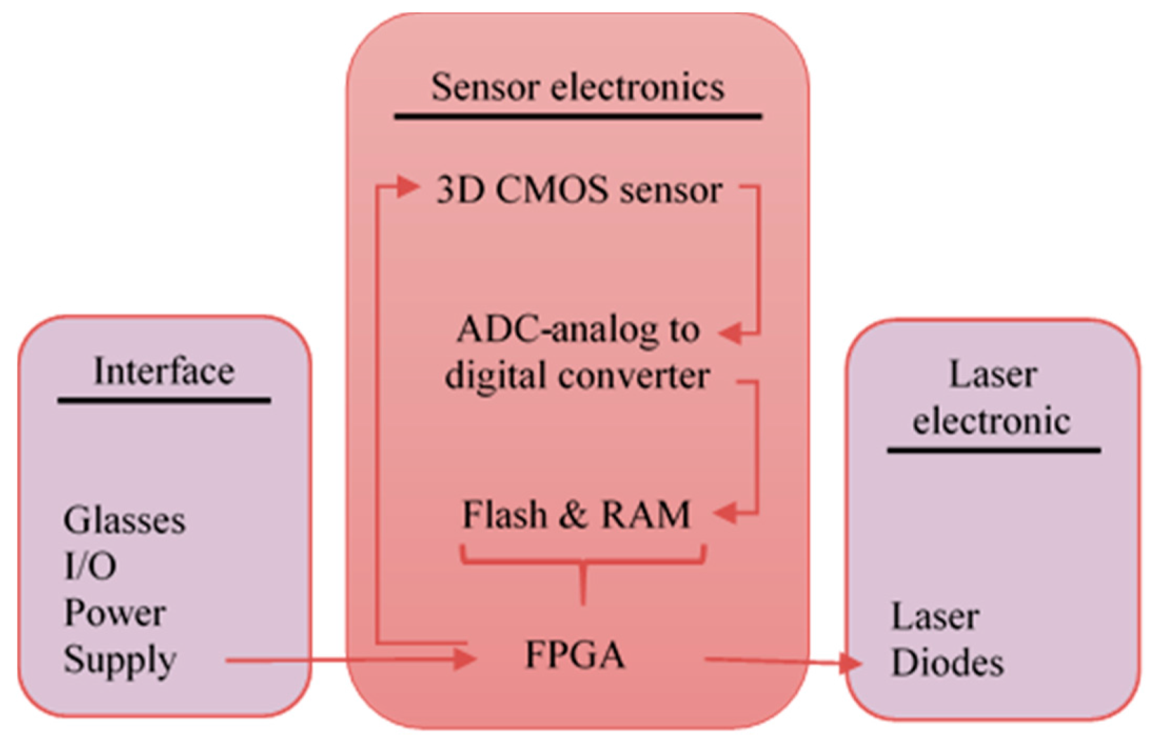
| CASBlip Weight: N/A Type of usage: pilot stage | 3D CMOS sensor | 80% in range of 0.5 m–5 m and less than 80% with further distance | Real time | Indoor/outdoor | 64° in azimuth | N/A | Small detection range Image acquisition technique needs more than 1X64 CMOS image sensor. Acoustic module needs to be improved (it can add sounds in elevation) | Day/Night | 0.5 m–5 m | Static | Binaural Acoustic module Multiple double short-time integration algorithms (MDSI) |
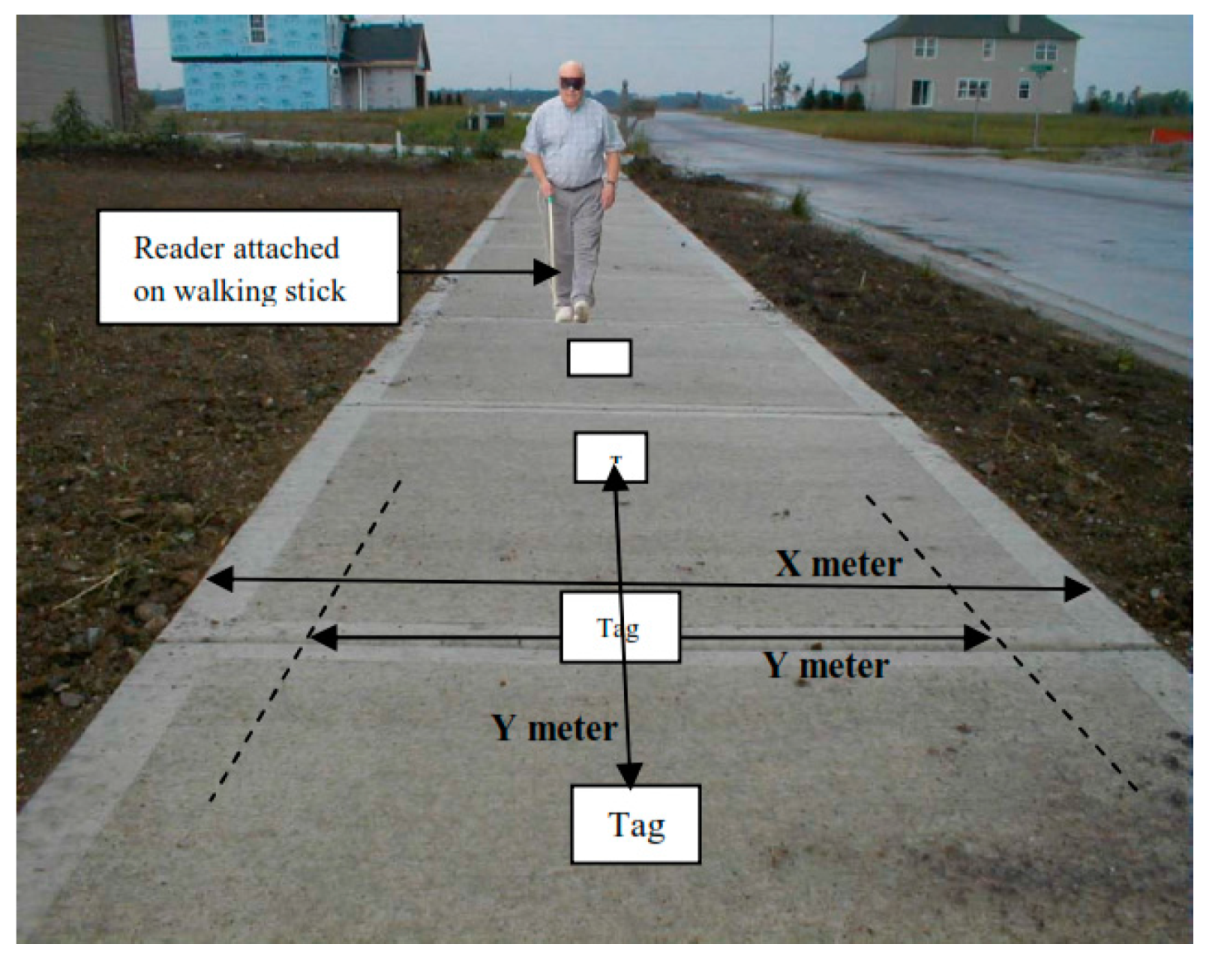
| RFIWS Weight: N/A Type of usage: research stage | None | N/A | Not-Real time | Outdoor | N/A | N/A | Collision of RFID Each tag needs specific rang which needs to be tested separated (scoop limitation) The tags cannot read the radio waves if case these tags get wrapped up or covered. | Day/Night | 1 m–3 m | Static | Ultra-high frequency (UHF) |
| A Low Cost Outdoor Assistive Navigation System Weight: N/A Type of usage: pilot stage | 3 Axial accelerometer sensors Magnetometer sensor | Good accuracy within residential area, but not as in an urban environment | Real time | Outdoor | N/A | $138 | The accuracy of GPS receiver in high rise building is degraded. Limited scope, the GPS receiver needs to be connected via Bluetooth to perform. | Day | N/A | Static | GPS technology Geo-Coder-US Module MoNav ModuleBluetooth |
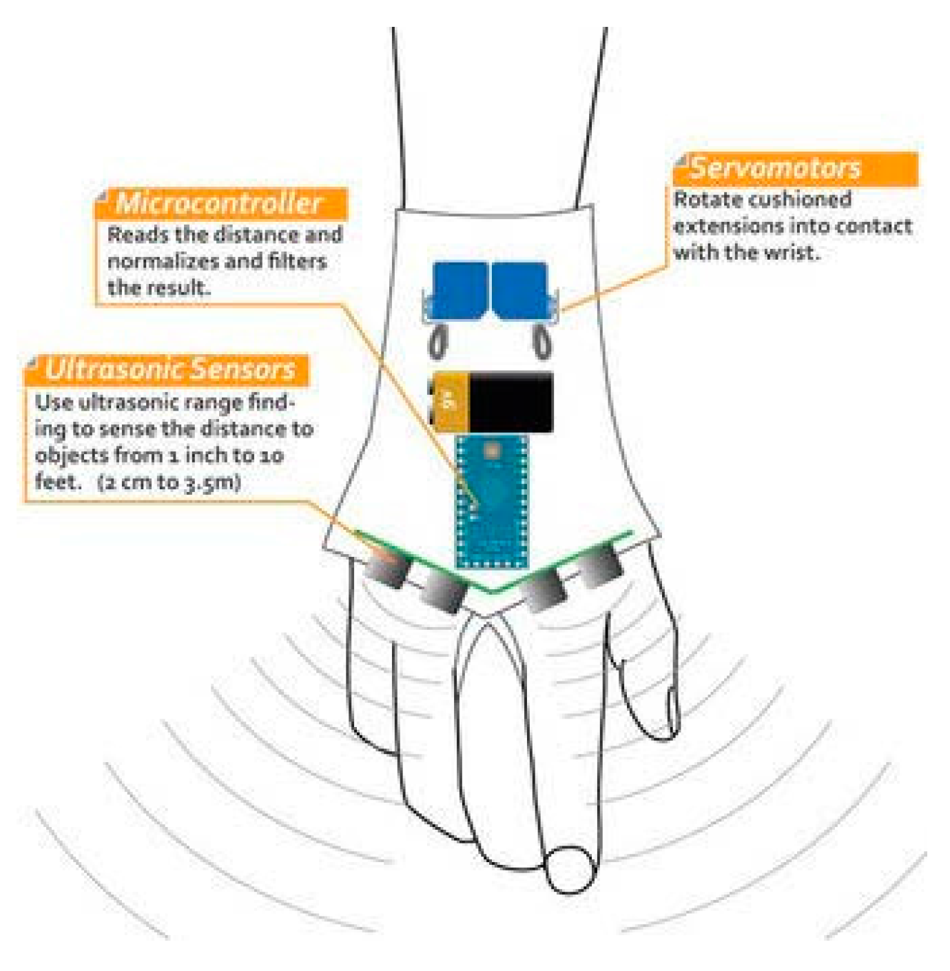
| ELC Weight: 0.170 Kg Type of usage: deployment stage | Ultrasonic sensor Micro-motor actuator | N/A | Real time | Outdoor | N/A | N/A | It is a detector device for physical obstacles above the waist line but the navigation still relies on the blind person. | Day/Night | Close objects over the waistline | Static | Ultrasonic sensor technology Haptics and tactile techniques |
| Cognitive Guidance System Weight: N/A Type of usage: pilot stage | Kinect sensor Video camera stereo Imaging sensor sonny ICx424 (640 × 480) RBG-D sensor for 3D point | N/A | Real time | Indoor | 180° | N/A | Only 49 Fuzzy rules were covered which cover 80 different configurations. The perception capacities of the system need to be increased to detect spatial landmarks. Improve the stabilization of reconstructed walking plane and its registration through the frame. | Day | 1.5 m–4.0 m | Static | The Canny filter for edge detection. Stereo vision, vanishing point and fuzzy rules (fuzzy logic and Mandani fuzzy decision system) to infer about the distances of objects. |
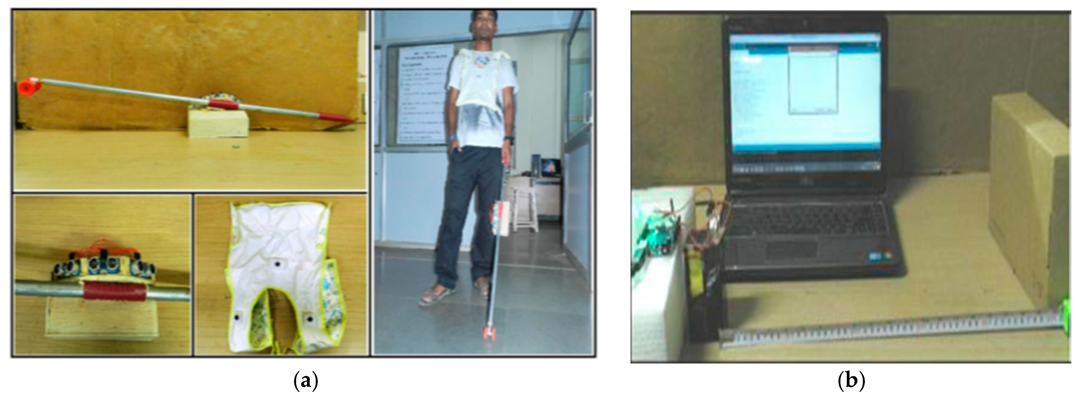
| Ultrasonic Cane as a Navigation Aid Weight: light Type of usage: pilot stage | Ultrasonic sensor (trans-receiver) Arduino UNO microcontroller wireless X-bee S1 trans receiver module | N/A | Real time | Indoor | 30° | N/A | Just an object detector Small detection rang Does not detect objects that suddenly appear | Day/Night | 5–150 cm | Static | Ultrasonic Technology |
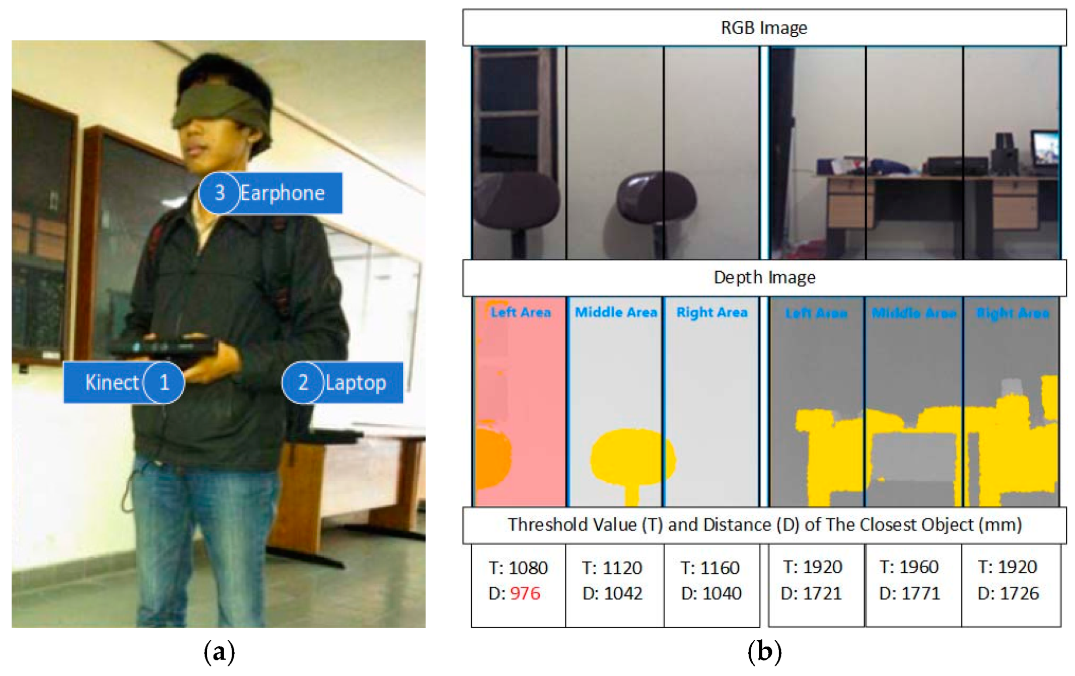
| Obstacle Avoidance Using Auto-adaptive Thresholding Weight: N/A Type of usage: pilot stage | Kinect’s depth camera | N/A | Real time | Indoor | Horizontal 57.50° and Vertical 43.5° | N/A | The accuracy of Kinect depth image decreases when the distance between the scene and sensor increase. Auto-adaptive threshold could not differentiate between the floor and the object after 2500 mm. That increases the average error of distance detection. The depth camera has to be carried which is a lot of load on the user’s hand. | Day | 0.8 m–4 m | Static/dynamic | Auto-adaptive Thresholding (divides equally a depth image into three areas. It finds the most optimal threshold value automatically (auto) and vary among each of those areas (adaptive). |
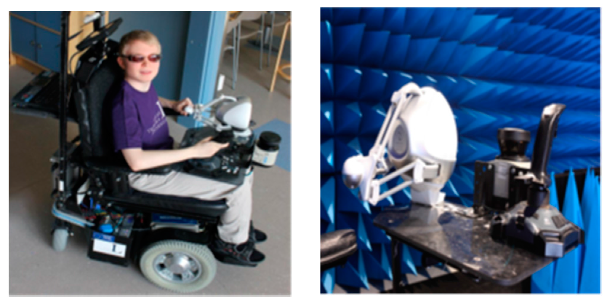
| Obstacle Avoidance Using Haptics and a Laser Rangefinder Weight: N/A Type of usage: pilot stage | Basely the system was built on the use of laser but the Novint Falcon has Encoder LED emitters and photo sensors Supplementary Sensors | N/A | Real time | Indoor | Horizontal 270° in front of chair | N/A | Precise location of obstacles and angles were difficult to determine. | Day | 20 m with 3 cm error | Static | Haptics and a Laser Rangefinder |
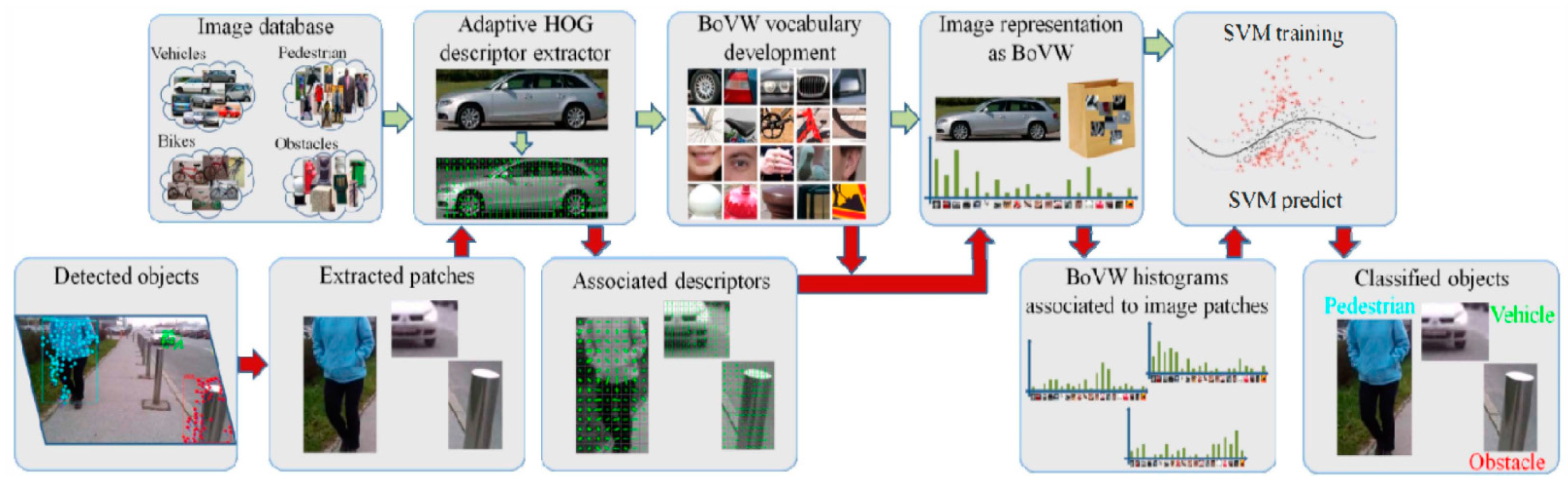
| A Computer Vision System that Ensure the Autonomous Navigation Weight: N/A Type of usage: deployment stage | Monocular camera | High Accuracy | Real time | Indoor/outdoor | Angular field of camera view of 69° | low | Their fixed sizes of the image based on the category can make detecting the same object with different sizes a challenge. Since the proposed system is based on a smartphone video camera; if the video camera is covered by the blind person’s clothes, then the system cannot work. The objects are in dark places and highly dynamic objects cannot be detected. The overhead and noise of smartphones videos. The tested dataset of 4500 images and dictionary of 4000 words are considered as a small dataset. The system is tested and it works only on a Samsung S4 which makes it limited in scope. | Day | Up to 10 m | Static/Dynamic | Lucas–Kanade algorithm and RANSAC algorithm are used for detection. Adapted HOG descriptor extractor, BoVW vocabulary development and SVM training are used for recognition. |
| Silicon Eyes Weight: N/A Type of usage: research stage | 24-bit color sensor SONAR obstacle detection light sensor 3-axis MEMS magnetometer 3-axis MEMS Accelerometer | N/A | Not-Real time | Not tested | N/A | N/A | A power supply meter reading needs to be installed to track the status. Low accuracy of GPS receiver in high rise buildings. The haptic feedback is not efficient. Limited memory of 2 GB micro-SD card to save user information. | Not tested | 2.5 cm–3.5 m | Static | GPS & GSM technology |
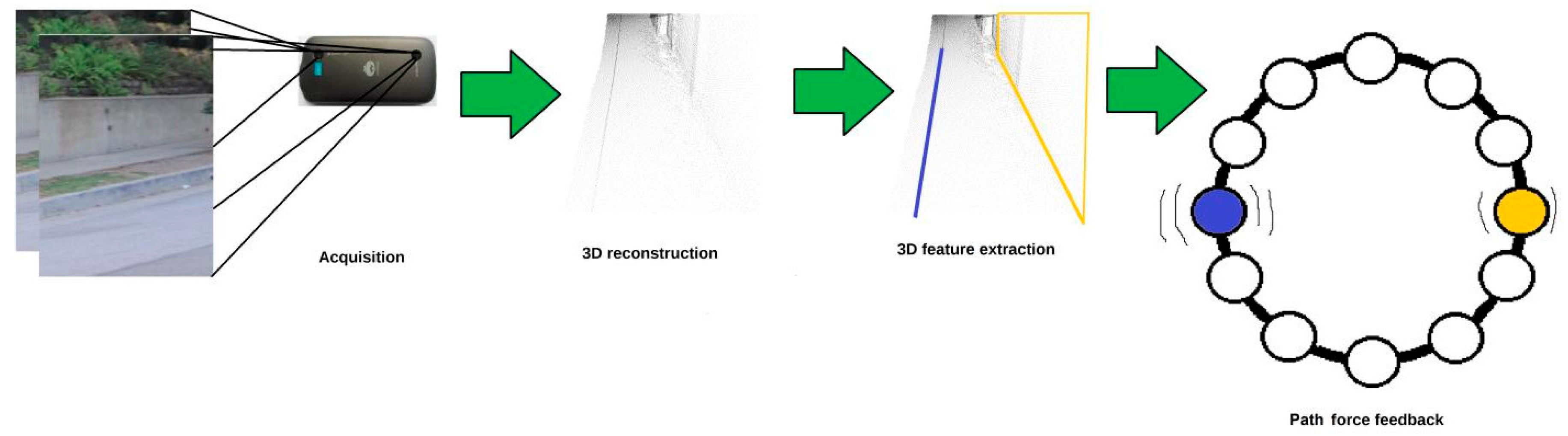
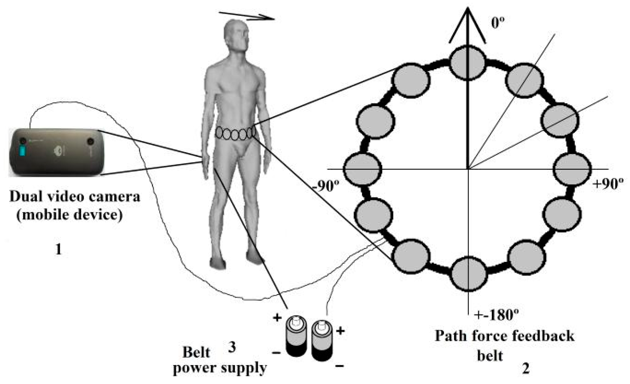
| A Path Force Feedback Belt Weight: N/A Type of usage: research stage | IR sensor Two depth sensors (sensor 2 dual video cameras type Kinect) | N/A | Not-Real Time | Outdoor | 360° over the blind’s waist | N/A | The detection range for this design is too small. The user needs to be trained in differentiating the vibration patterns for each cell. Using vibration patterns as feedback instead of audio format is not an excellent solution as the person can lose the sense of discrimination of such techniques over the time. | Not tested | Short | Static/dynamic | Infrared technology and GPS |
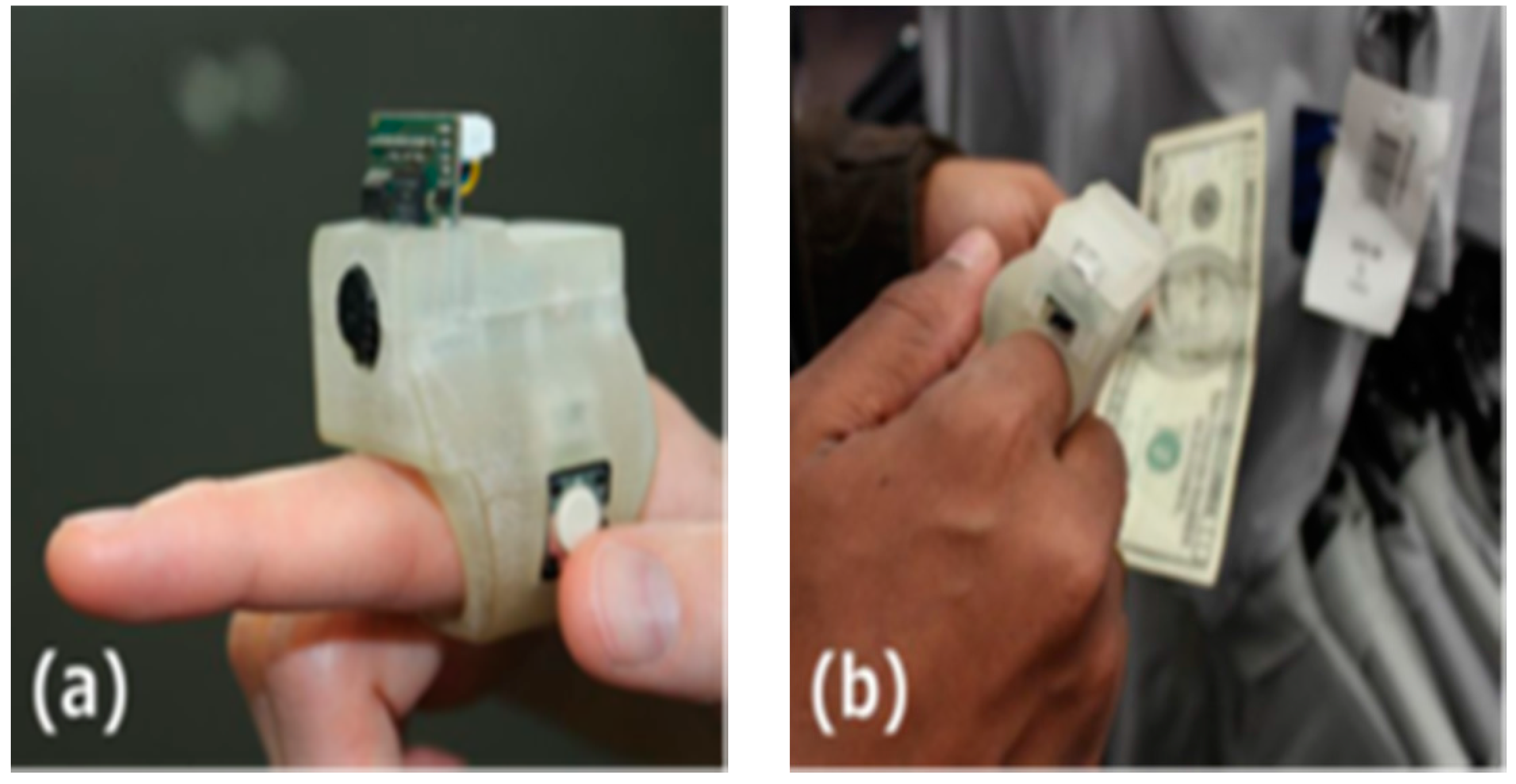
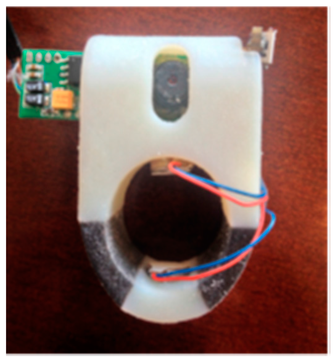
| EyeRing Weight: N/A Type of usage: pilot stage | Atmel 8 bit microcontroller OV7725 VGA CMOS sensor for image acquisition | N/A | Real time | Indoor/outdoor | Not Applicable | N/A | The system does not provide a real time video feedback. The system is limited to single object detection, which cannot be very useful to the disabled person. | Day | Close up view | Static | Roving Networks RN-42 Bluetooth module |
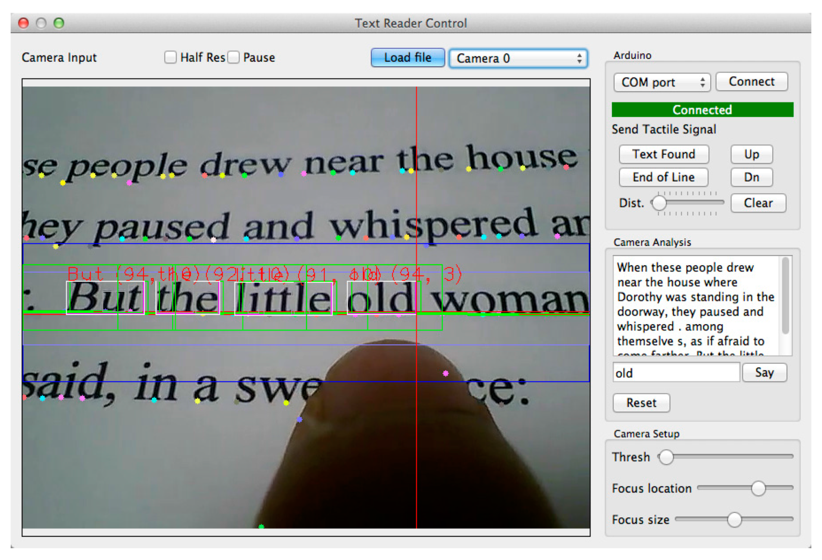
| FingerReader Weight: N/A Type of usage: pilot stage | Atmel 8 bit microcontroller OV7725 VGA CMOS sensor for image acquisition Vibration motors | 93.9% | Real time tactile feedback20 m processing time | Indoor/outdoor | Not Applicable | N/A | There is a real time response for the audio feedback, but there is a long stop between the instructions. Also, the system prototype contains two pieces one is the ring, the other is the computation element which need to be carried all the time by the user for I/0 speech, otherwise the user will not be able to receive the feedback. | Day | Close up view | Static | Roving Networks RN-42 Bluetooth module |
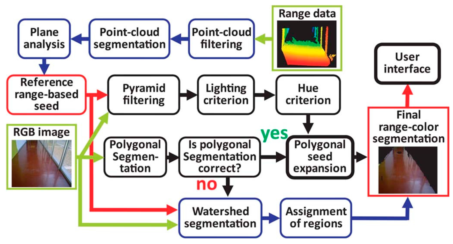
| Navigation Assistance Using RGB-D Sensor With Range Expansion Weight: N/A Type of usage: pilot stage | RGB-D sensor | 95% | Real time | Indoor | N/A | low | The effective of the infrared to the sunlight can negatively affect the performance of the system outdoors and during the day time. | Night | Up to 3 m using range information technique and from 3 m and further using the vision information | Static | RANdom Sample Consensus (RANSA) detection algorithm Image intensities and depth information (computer vision) Infrared technology and density images |
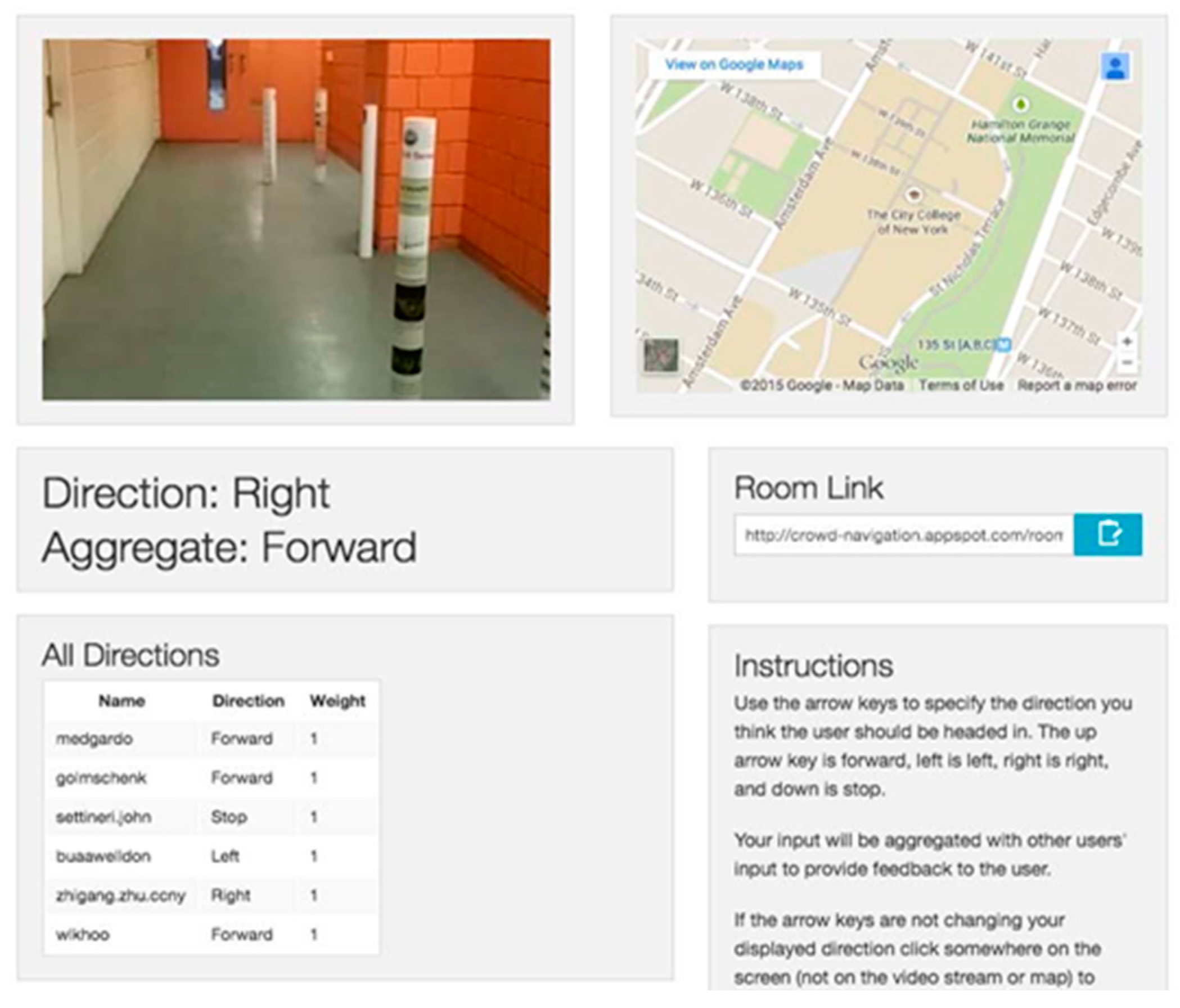
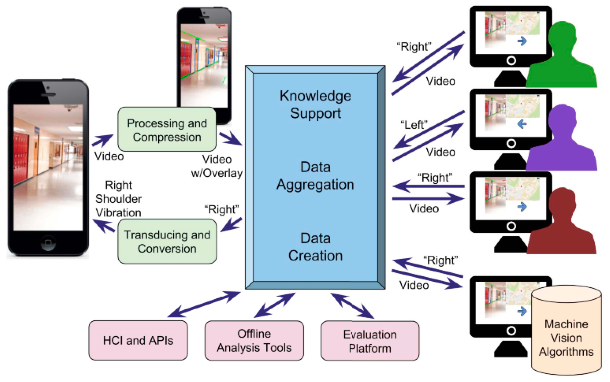
| Mobile Crowd Assisted Navigation for the Visually-impaired Weight: N/A Type of usage: pilot stage | Camera GPS Compass Accelerometer | 20.5% improvement in crowd sound for navigation | Real time | Indoor | N/A | N/A | The collected information is based on the volunteers’ availability. There is a possibility of no input in the interval time which fails the goal of the service. | Day/Night | N/A | Dynamic | Crowd sounding service through Goagle engine for navigation Machine vision algorithm |
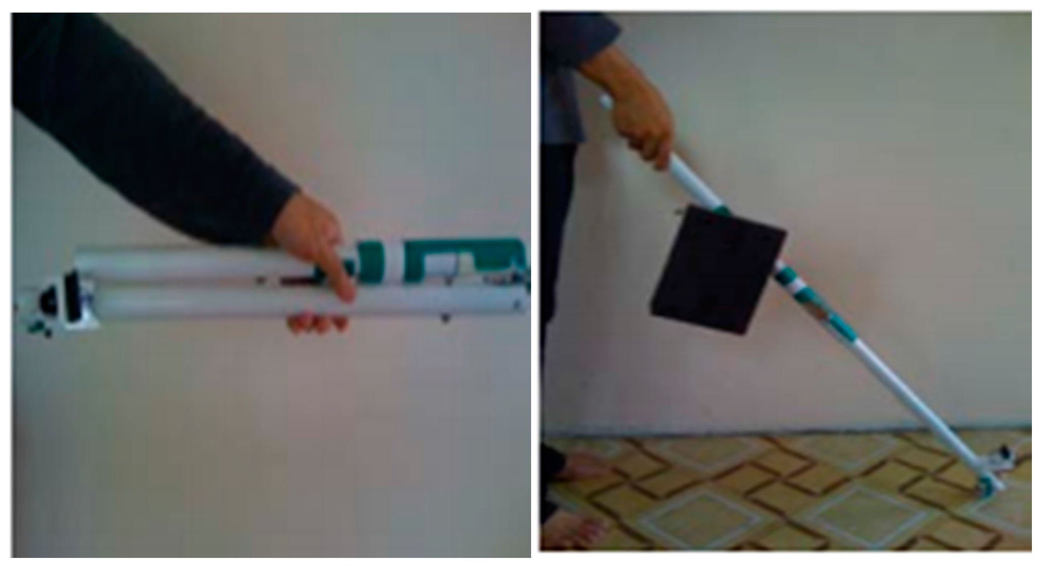
| A Design of Blind-guide Crutch Based on Multi-sensors Weight: N/A Type of usage: deployment stage | 3 Ultrasonic sensors | N/A | Real time | Outdoor | 30° detection range for 2 sensors, 80° detection range for overhead | N/A | The detection range is small. This system is claimed to be navigation system, however, there are no given directions to the user. | Day | 0 m–2 m in front | Static | Ultrasonic distance measurement approach |
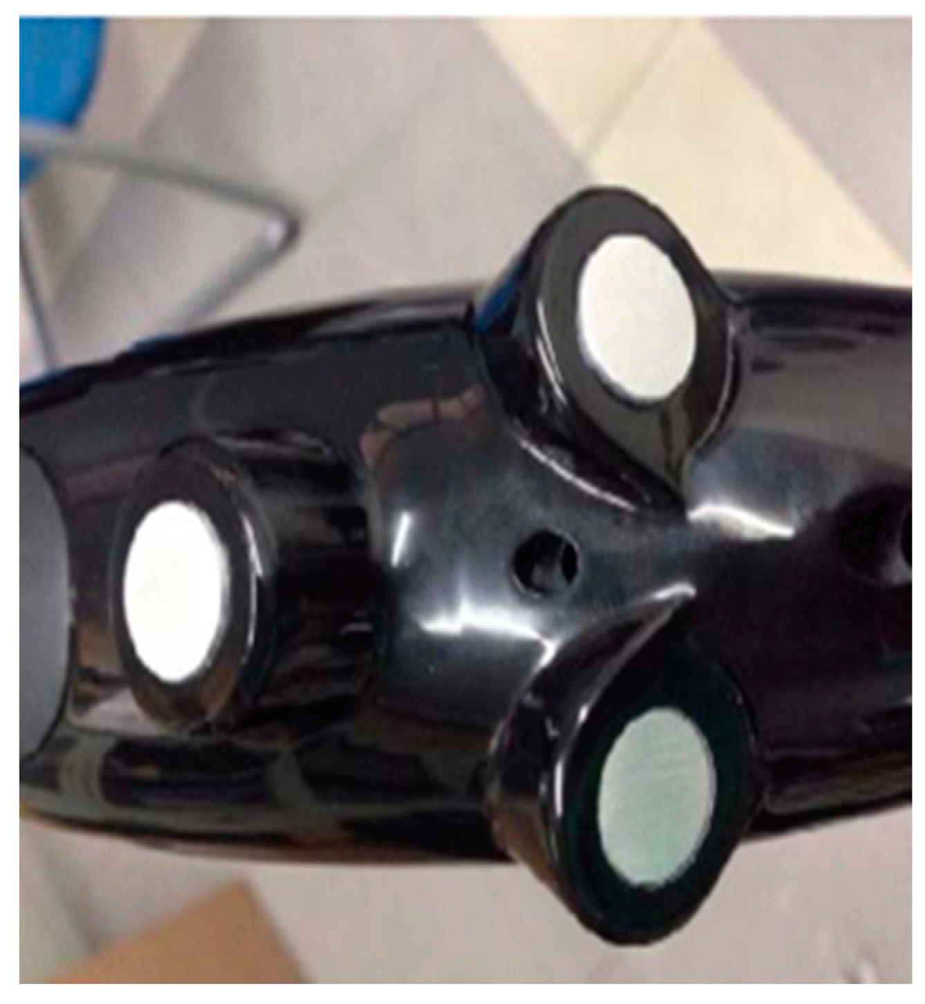
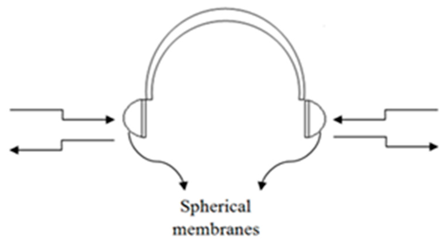
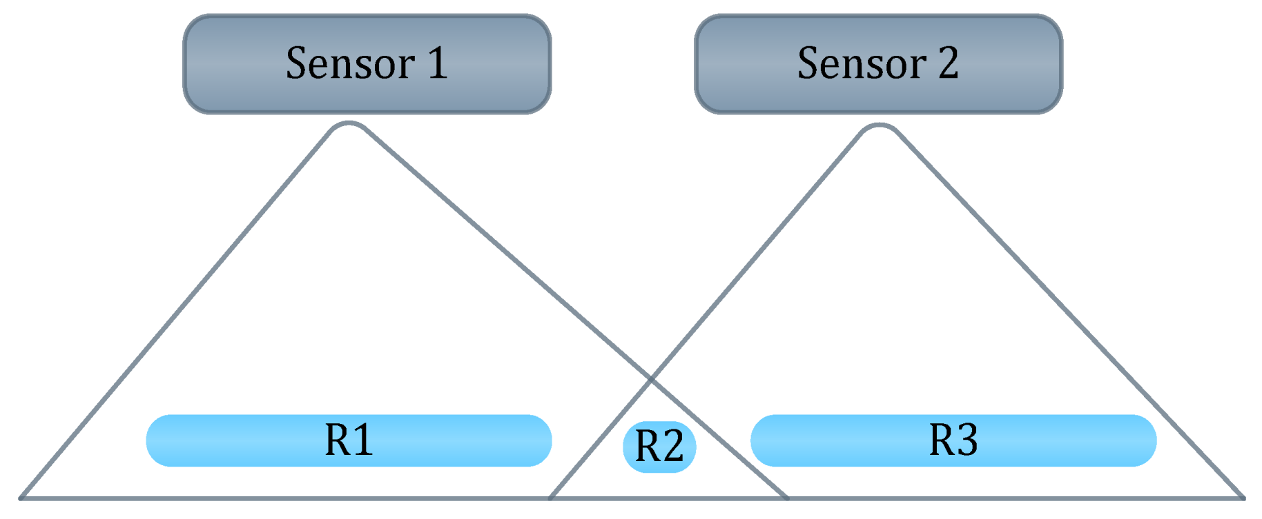
| Ultrasonic Assistive Headset for visually-impaired people Weight: light Type of usage: pilot stage | 4 Ultrasonic type (DYP-ME007) sensor obstacle detector | N/A | Real time | Indoor/outdoor | 60° between ultrasonic distance sensors | N/A | Limited directions are provided. The headset obscures the external noise. | Day/Night | 3 cm–4 m | Static | Ultrasonic technology |
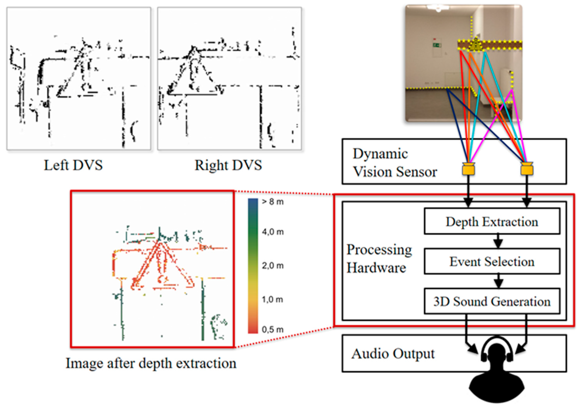
| A Mobility Device for the Blind with Improved Vertical Resolution Using Dynamic Vision Sensors Weight: light Type of usage: pilot stage | 2 retine-inspired dynamic vision sensors (DVS) | 99% ± object detection, 90% ± 8% horizontal localization, 96% ± 5.3% size discrimination | Real time | Indoor | N/A | low | The modules are very expensive. Further intensive tests need to be done to show the performance object avoidance and navigation techniques, whereas, the test was mainly on object detection technique for the central area of the scene. | Day | 0.5 m–8 m | Dynamic/static | Event-based algorithm |
| Ultrasonic for ObstDetectRec Weight: 750 gram Type of usage: pilot stage | 4 ultrasonic sensors (Maxsonar LV EZ-0) | N/A | Real time | Indoor/outdoor | ±40° | Low | The system cannot detect obstacles above waist level. There is no navigational information provided. Small detection range. It is not an independent device. | Day | 2 < R ≤ 5 m | Static/dynamic | Vision-based object detection module. Ultrasonic technology. SVM |
| SUGAR system Weight: N/A Type of usage: pilot stage | Ultra-wide band Sensors(UWB) | High Accuracy | Real time | Indoor | N/A | N/A | Sensors would have to be deployed in every room. The room has to be mapped beforehand. User needs to select destination beforehand. It is not suitable for outside use. | Day (the system was not tested for night time) | 50 m–60 m | static | UWB positioning technique Path Finding Algorithm Time Difference of Arrival technique (TDOA) |
References
- World Health Organization. Visual Impairment and Blindness. Available online: http://www.Awho.int/mediacentre/factsheets/fs282/en/ (accessed on 24 January 2016).
- American Foundation for the Blind. Available online: http://www.afb.org/ (accessed on 24 January 2016).
- National Federation of the Blind. Available online: http://www.nfb.org/ (accessed on 24 January 2016).
- Velázquez, R. Wearable assistive devices for the blind. In Wearable and Autonomous Biomedical Devices and Systems for Smart Environment; Springer: Berlin/Heidelberg, Germany, 2010; pp. 331–349. [Google Scholar]
- Baldwin, D. Wayfinding technology: A road map to the future. J. Vis. Impair. Blind. 2003, 97, 612–620. [Google Scholar]
- Blasch, B.B.; Wiener, W.R.; Welsh, R.L. Foundations of Orientation and Mobility, 2nd ed.; AFB Press: New York, NY, USA, 1997. [Google Scholar]
- Shah, C.; Bouzit, M.; Youssef, M.; Vasquez, L. Evaluation of RUNetra tactile feedback navigation system for the visually-impaired. In Proceedings of the International Workshop on Virtual Rehabilitation, New York, NY, USA, 29–30 August 2006; pp. 72–77.
- Hersh, M.A. The Design and Evaluation of Assistive Technology Products and Devices Part 1: Design. In International Encyclopedia of Rehabilitation; CIRRIE: Buffalo, NY, USA, 2010. [Google Scholar]
- Marion, A.H.; Michael, A.J. Assistive technology for Visually-impaired and Blind People; Springer: London, UK, 2008. [Google Scholar]
- Tiponut, V.; Ianchis, D.; Bash, M.; Haraszy, Z. Work Directions and New Results in Electronic Travel Aids for Blind and Visually Impaired People. Latest Trends Syst. 2011, 2, 347–353. [Google Scholar]
- Tiponut, V.; Popescu, S.; Bogdanov, I.; Caleanu, C. Obstacles Detection System for Visually-impaired Guidance. New Aspects of system. In Proceedings of the 12th WSEAS International Conference on SYSTEMS, Heraklion, Greece, 14–17 July 2008; pp. 350–356.
- Dakopoulos, D.; Bourbakis, N.G. Wearable obstacle avoidance electronic travel aids for blind: A survey. IEEE Trans. Syst. Man Cybern. Part C 2010, 40, 25–35. [Google Scholar] [CrossRef]
- Renier, L.; De Volder, A.G. Vision substitution and depth perception: Early blind subjects experience visual perspective through their ears. Disabil. Rehabil. Assist. Technol. 2010, 5, 175–183. [Google Scholar] [CrossRef]
- Tapu, R.; Mocanu, B.; Tapu, E. A survey on wearable devices used to assist the visual impaired user navigation in outdoor environments. In Proceedings of the 2014 11th International Symposium on Electronics and Telecommunications (ISETC), Timisoara, Romania, 14–15 November 2014.
- Liu, J.; Liu, J.; Xu, L.; Jin, W. Electronic travel aids for the blind based on sensory substitution. In Proceedings of the 2010 5th International Conference on Computer Science and Education (ICCSE), Hefei, China, 24–27 August 2010.
- Sánchez, J.; Elías, M. Guidelines for designing mobility and orientation software for blind children. In Proceedings of the IFIP Conference on Human-Computer Interaction, Janeiro, Brazil, 10–14 September 2007.
- Farcy, R.; Leroux, R.; Jucha, A.; Damaschini, R.; Grégoire, C.; Zogaghi, A. Electronic travel aids and electronic orientation aids for blind people: Technical, rehabilitation and everyday life points of view. In Proceedings of the Conference & Workshop on Assistive Technologies for People with Vision & Hearing Impairments Technology for Inclusion, Los Alamitos, CA, USA, 9–11 July 2006.
- Kammoun, S.; Marc, J.-M.; Oriola, B.; Christophe, J. Toward a better guidance in wearable electronic orientation aids. In Proceedings of the IFIP Conference on Human-Computer Interaction, Lisbon, Portugal, 5–9 September 2011.
- Wahab, A.; Helmy, M.; Talib, A.A.; Kadir, H.A.; Johari, A.; Noraziah, A.; Sidek, R.M.; Mutalib, A.A. Smart Cane: Assistive Cane for Visually-impaired People. Int. J. Comput. Sci. Issues 2011, 8, 4. [Google Scholar]
- Bharambe, S.; Thakker, R.; Patil, H.; Bhurchandi, K.M. Substitute Eyes for Blind with Navigator Using Android. In Proceedings of the India Educators Conference (TIIEC), Bangalore, India, 4–6 April 2013; pp. 38–43.
- Vítek, S.; Klima, M.; Husnik, L.; Spirk, D. New possibilities for blind people navigation. In Proceedings of the 2011 International Conference on Applied Electronics (AE), Pilsen, Czech, 7–8 September 2011; pp. 1–4.
- Brilhault, A.; Kammoun, S.; Gutierrez, O.; Truillet, P.; Jouffrais, C. Fusion of artificial vision and GPS to improve blind pedestrian positioning. In Proceedings of the 4th IFIP International Conference on New Technologies, Mobility and Security (NTMS), Paris, France, 7–10 February 2011; pp. 1–5.
- White, C.E.; Bernstein, D.; Kornhauser, A.L. Some map matching algorithms for personal navigation assistants. Trans. Res. C Emerg. Tech. 2000, 8, 91–108. [Google Scholar] [CrossRef]
- Loomis, J.M.; Golledge, R.G.; Klatzky, R.L.; Speigle, J.M.; Tietz, J. Personal guidance system for the visually impaired. In Proceedings of the First Annual ACM Conference on Assistive Technologies, Marina Del Rey, CA, USA, 31 October–1 November 1994.
- Delorme, A.; Thorpe, S.J. SpikeNET: An event-driven simulation package for modelling large networks of spiking neurons. Netw. Comput. Neural Syst. 2003, 14, 613–627. [Google Scholar] [CrossRef]
- Sirikham, A.; Chiracharit, W.; Chamnongthai, K. Banknote and coin speaker device for blind people. In Proceedings of the 11th International Conference on Advanced Communication Technology (ICACT), Phoenix Park, Korea, 15–18 February 2009; pp. 2137–2140.
- Dunai Dunai, L.; Chillarón Pérez, M.; Peris-Fajarnés, G.; Lengua Lengua, I. Euro Banknote Recognition System for Blind People. Sensors 2017, 17, 184. [Google Scholar] [CrossRef] [PubMed]
- Nguyen, T.H.; Le, T.L.; Tran, T.T.H.; Vuillerme, N.; Vuong, T.P. Antenna Design for Tongue electrotactile assistive device for the blind and visually-impaired. In Proceedings of the 2013 7th European Conference on Antennas and Propagation (EuCAP), Gothenburg, Sweden, 8–12 April 2013; pp. 1183–1186.
- Icheln, C.; Krogerus, J.; Vainikainen, P. Use of Balun Chokes in Small-Antenna Radiation Measurements. IEEE Trans. Instrum. Meas. 2004, 53, 498–506. [Google Scholar] [CrossRef]
- Nguyen, T.H.; Nguyen, T.H.; Le, T.L.; Tran, T.T.H.; Vuillerme, N.; Vuong, T.P. A wearable assistive device for the blind using tongue-placed electrotactile display: Design and verification. In Proceedings of the 2013 International Conference on Control, Automation and Information Sciences (ICCAIS), Nha Trang, Vietnam, 25–28 November 2013.
- Dunai, L.; Garcia, B.D.; Lengua, I.; Peris-Fajarnés, G. 3D CMOS sensor based acoustic object detection and navigation system for blind people. In Proceedings of the 38th Annual Conference on IEEE Industrial Electronics Society (IECON 2012), Montreal, QC, Canada, 25–28 October 2012.
- Saaid, M.F.; Ismail, I.; Noor, M.Z.H. Radio frequency identification walking stick (RFIWS): A device for the blind. In Proceedings of the 5th International Colloquium on Signal Processing & Its Applications, Kuala Lumpur, Malaysia, 6–8 March 2009.
- Harrison, M.; McFarlane, D.; Parlikad, A.K.; Wong, C.Y. Information management in the product lifecycle-the role of networked RFID. In Proceedings of the 2nd IEEE International Conference on Industrial Informatics (INDIN’04), Berlin, Germany, 24–26 June 2004.
- Xiao, J.; Ramdath, K.; Losilevish, M.; Sigh, D.; Tsakas, A. A low cost outdoor assistive navigation system for blind people. In Proceedings of the 2013 8th IEEE Conference on Industrial Electronics and Applications (ICIEA), Melbourne, Australia, 19–21 June 2013; pp. 828–833.
- Fonseca, R. Electronic long cane for locomotion improving on visual impaired people: A case study. In Proceedings of the 2011 Pan American Health Care Exchanges (PAHCE), Rio de Janeiro, Brazil, 28 March–1 April 2011.
- Landa-Hernández, A.; Bayro-Corrochano, E. Cognitive guidance system for the blind. In Proceedings of the IEEE World Automation Congress (WAC), Puerto Vallarta, Mexico, 24–28 June 2012.
- Benjamin, J.M. The Laser Cane. J. Rehabil. Res. Dev. 1974, 10, 443–450. [Google Scholar]
- Kumar, K.; Champaty, B.; Uvanesh, K.; Chachan, R.; Pal, K.; Anis, A. Development of an ultrasonic cane as a navigation aid for the blind people. In Proceedings of the 2014 International Conference on Control, Instrumentation, Communication and Computational Technologies (ICCICCT), Kanyakumari District, India, 10–11 July 2014.
- Saputra, M.R.U.; Santosa, P.I. Obstacle Avoidance for Visually Impaired Using Auto-Adaptive Thresholding on Kinect’s Depth Image. In Proceedings of the IEEE 14th International Conference on Scalable Computing and Communications and Its Associated Workshops (UTC-ATC-ScalCom), Bali, Indonesia, 9–12 December 2014.
- Jassim, F.A.; Altaani, F.H. Hybridization of Otsu Method and Median Filter for Color Image Segmentation. Int. J. Soft Comput. Eng. 2013, 3, 69–74. [Google Scholar]
- Ahlmark, I.; Hakan Fredriksson, D.; Hyyppa, K. Obstacle avoidance using haptics and a laser rangefinder. In Proceedings of the 2013 IEEE Workshop on Advanced Robotics and its Social Impacts (ARSO), Tokyo, Japan, 7–9 November 2013.
- SenseGrapics AB, Open Source Haptics—H3D.org. Available online: http://www.h3dapi.org/ (accessed on 18 June 2016).
- Tapu, R.; Mocanu, B.; Zaharia, T. A computer vision system that ensure the autonomous navigation of blind people. In Proceedings of the IEEE E-Health and Bioengineering Conference (EHB), Iasi, Romania, 21–23 November 2013.
- Tapu, R.; Mocanu, B.; Zaharia, T. Real time static/dynamic obstacle detection for visually impaired persons. In Proceedings of the 2014 IEEE International Conference on Consumer Electronics (ICCE), Las Vegas, NV, USA, 10–13 January 2014.
- Prudhvi, B.R.; Bagani, R. Silicon eyes: GPS-GSM based navigation assistant for visually impaired using capacitive touch braille keypad and smart SMS facility. In Proceedings of the 2013 World Congress on Computer and Information Technology (WCCIT), Sousse, Tunisia, 22–24 June 2013.
- Fradinho Oliveira, J. The path force feedback belt. In Proceedings of the 2013 8th International Conference on Information Technology in Asia (CITA), Kuching, Malaysia, 1–4 July 2013.
- Shilkrot, R.; Huber, J.; Liu, C.; Maes, P.; Nanayakkara, S.C. Fingerreader: A wearable device to support text reading on the go. In Proceedings of the CHI’14 Extended Abstracts on Human Factors in Computing Systems, Toronto, ON, Canada, 26 April–1 May 2014.
- Nanayakkara, S.; Shilkrot, R.; Yeo, K.P.; Maes, P. EyeRing: A finger-worn input device for seamless interactions with our surroundings. In Proceedings of the 4th Augmented Human International Conference, Stuttgart, Germany, 7–8 March 2013.
- Black, A.W.; Lenzo, K.A. Flite: A small fast run-time synthesis engine. In Proceedings of the ITRW on Speech Synthesis, Perthshire, Scotland, 29 August–1 September 2001.
- Smith, R. An overview of the tesseract OCR engine. In Proceedings of the ICDAR, Paraná, Brazil, 23–26 September 2007; pp. 629–633.
- Aladren, A.; Lopez-Nicolas, G.; Puig, L.; Guerrero, J.J. Navigation Assistance for the Visually Impaired Using RGB-D Sensor with Range Expansion. IEEE Syst. J. 2016, 10, 922–932. [Google Scholar] [CrossRef]
- Kiryati, N.; Eldar, Y.; Bruckstein, M. A probabilistic Hough transform. Pattern Recogn. 1991, 24, 303–316. [Google Scholar] [CrossRef]
- Olmschenk, G.; Yang, C.; Zhu, Z.; Tong, H.; Seiple, W.H. Mobile crowd assisted navigation for the visually impaired. In Proceedings of the 2015 IEEE 15th International Conference on Scalable Computing and Communications and Its Associated Workshops (UIC-ATC-ScalCom), Beijing, China, 10–14 August 2015.
- Yi, Y.; Dong, L. A design of blind-guide crutch based on multi-sensors. In Proceedings of the 2015 12th International Conference on Fuzzy Systems and Knowledge Discovery (FSKD), Zhangjiajie, China, 15–17 August 2015.
- Aymaz, Ş.; Çavdar, T. Ultrasonic Assistive Headset for visually impaired people. In Proceedings of the 2016 39th International Conference on Telecommunications and Signal Processing (TSP), Vienna, Austria, 27–29 June 2016.
- Everding, L.; Walger, L.; Ghaderi, V.S.; Conradt, J. A mobility device for the blind with improved vertical resolution using dynamic vision sensors. In Proceedings of the 2016 IEEE 18th International Conference on e-Health Networking, Applications and Services (Healthcom), Munich, Germany, 14–16 September 2016.
- Ghaderi, V.S.; Mulas, M.; Pereira, V.F. S.; Everding, L.; Weikersdorfer, D.; Conradt, J. A wearable mobility device for the blind using retinainspired dynamic vision sensors. In Proceedings of the 37th Annual International Conference of the IEEE Engineering in Medicine and Biology Society (EMBC), Milan, Italy, 25–29 August 2015.
- Mueggler, E.; Forster, C.; Baumli, N.; Gallego, G.; Scaramuzza, D. Lifetime estimation of events from Dynamic Vision Sensors. In Proceedings of the 2015 IEEE International Conference on Robotics and Automation (ICRA), Seattle, WA, USA, 26–30 May 2015.
- Nancy Owano. Dynamic Vision Sensor Tech Works Like Human Retina. Available online: http://phys.org/news/2013–08-dynamic-vision-sensor-tech-human.html (accessed on 13 August 2016).
- Mocanu, B.; Tapu, R.; Zaharia, T. When Ultrasonic Sensors and Computer Vision Join Forces for Efficient Obstacle Detection and Recognition. Sensors 2016, 16, 1807. [Google Scholar] [CrossRef]
- Martinez-Sala, A.S.; Losilla, F.; Sánchez-Aarnoutse, J.C.; García-Haro, J. Design, implementation and evaluation of an indoor navigation system for visually-impaired people. Sensors 2015, 15, 32168–32187. [Google Scholar] [CrossRef]
- Photonics, H. Characteristics and Use of Infrared Detectors. Available online: https://www.hamamatsu.com/resources/pdf/ssd/infrared_kird9001e.pdf (accessed on 8 February 2017).
- McCathie, L. The Advantages and Disadvantages of Barcodes and Radio Frequency Identification in Supply Chain Management; University of Wollongong: Wollongong, NSW, Australia, 2004. [Google Scholar]
- Andersen, M.R.; Jensen, T.; Lisouski, P.; Mortensen, A.K.; Hansen, M.K.; Gregersen, T.; Ahrendt, P. Kinect Depth Sensor Evaluation for Computer Vision Applications; Electrical and Computer Engineering Technical Report ECE-TR-6; Aarhus University: Aarhus, Denmark, 2012. [Google Scholar]
- Neto, L.B.; Grijalva, F.; Maike, V.R.M.L.; Martini, L.C.; Florencio, D.; Baranauskas, M.C.C.; Rocha, A.; Goldenstein, S. A Kinect-Based Wearable Face Recognition System to Aid Visually-impaired Users. IEEE Trans. Hum.-Mach. Syst. 2016, 47, 52–64. [Google Scholar] [CrossRef]
- AIRMAR, Tech. Overview for Applying Ultrasonic Technology (AirducerTM Catalog). Available online: www.airmar.com (accessed on June 2016).
- Pieralisi, M.; Petrini, V.; Di Mattia, V.; Manfredi, G.; De Leo, A.; Scalise, L.; Russo, P.; Cerri, G. Design and realization of an electromagnetic guiding system for blind running athletes. Sensors 2015, 15, 16466–16483. [Google Scholar] [CrossRef]
- Pieralisi, M.; Di Mattia, V.; Petrini, V.; De Leo, A.; Manfredi, G.; Russo, P.; Scalise, L.; Cerri, G. An Electromagnetic Sensor for the Autonomous Running of Visually-impaired and Blind Athletes (Part I: The Fixed Infrastructure). Sensors 2017, 17, 364. [Google Scholar] [CrossRef] [PubMed]


| Feature | Description |
|---|---|
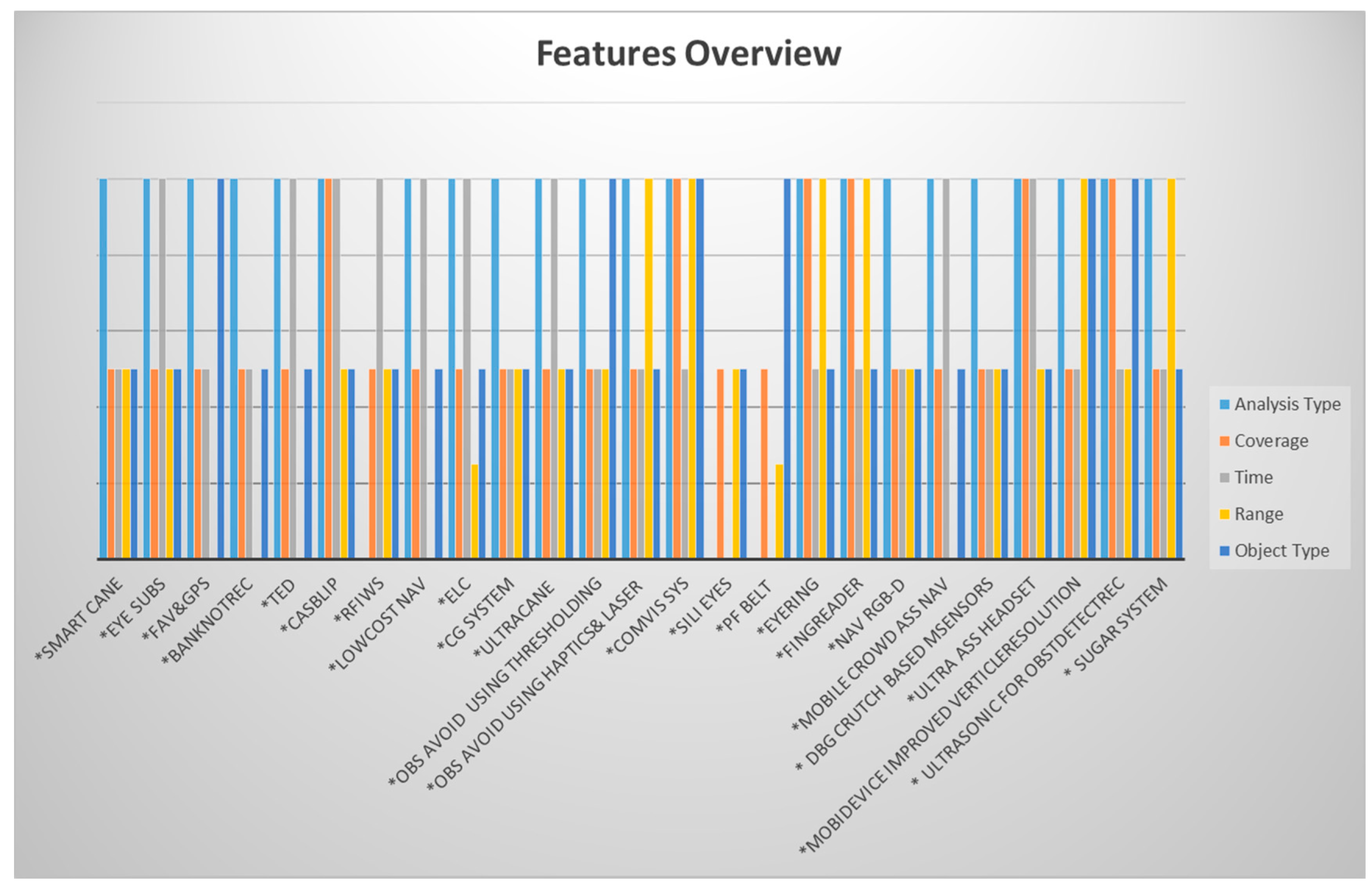
| Analysis Type | The system needs to provide a fast processing for the exchanged information between the user and sensors. For example, the system that detects the obstacle that is 2 m in front of the user in 10 s cannot be considered as real time system [12] |
| Coverage | The system needs to provide its services indoors and outdoors to improve the quality of visually-impaired people’s lives |
| Time | The system should perform as well in day time as at night time |
| Range | It is the distance between the user and the object to be detected by the system. Ideal minimum range is 0.5 m, whereas the maximum range should be more than 5 m. Further distance is better |
| Object Type | The system should avoid the sudden appearance objects, which means the system should detect the dynamic objects as the static objects |
| System | Features | |||||
|---|---|---|---|---|---|---|
| Real Time/not Real Time | Coverage (Indoor, Outdoor, both) | Time (Day, Night, both) | Range (R ≤ 1 m, 1 m < R ≤ 5 m, R > 5 m) | Object Type (Static, Dynamic, both) | Total Score | |
| Weight of 10 | ||||||
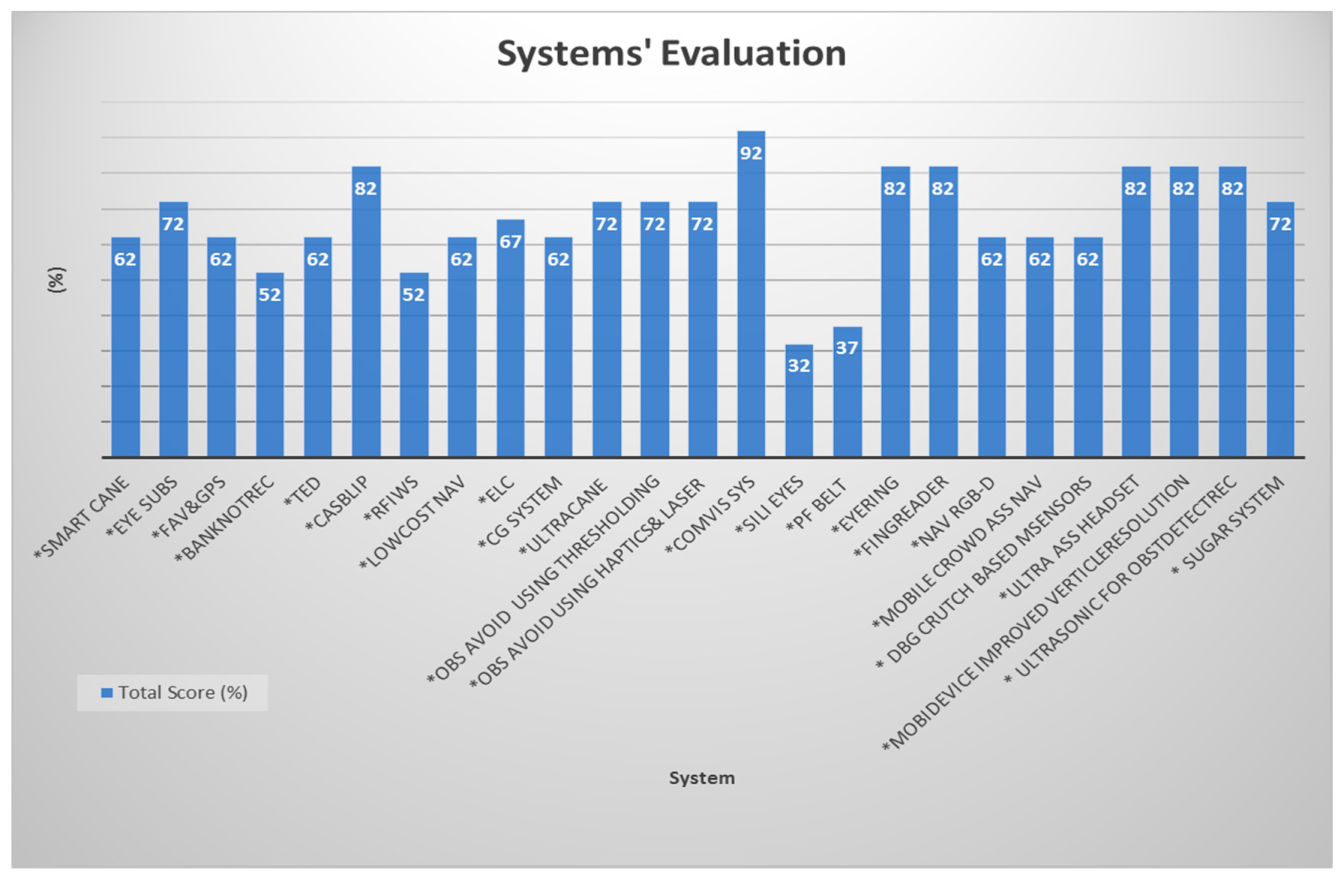
| *Smart Cane | 10 | 5 | 5 | 5 | 5 | 62 |
| *Eye Subs | 10 | 5 | 10 | 5 | 5 | 72 |
| *FAV&GPS | 10 | 5 | 5 | - | 10 | 62 |
| *BanknotRec | 10 | 5 | 5 | - | 5 | 52 |
| *TED | 10 | 5 | 10 | - | 5 | 62 |
| *CASBlip | 10 | 10 | 10 | 5 | 5 | 82 |
| *RFIWS | - | 5 | 10 | 5 | 5 | 52 |
| *LowCost Nav | 10 | 5 | 10 | - | 5 | 62 |
| *ELC | 10 | 5 | 10 | 2.5 | 5 | 67 |
| *CG System | 10 | 5 | 5 | 5 | 5 | 62 |
| *UltraCane | 10 | 5 | 10 | 5 | 5 | 72 |
| *Obs Avoid using Thresholding | 10 | 5 | 5 | 5 | 10 | 72 |
| *Obs Avoid using Haptics&Laser | 10 | 5 | 5 | 10 | 5 | 72 |
| *ComVis Sys | 10 | 10 | 5 | 10 | 10 | 92 |
| *Sili Eyes | - | 5 | - | 5 | 5 | 32 |
| *PF belt | - | 5 | - | 2.5 | 10 | 37 |
| *EyeRing | 10 | 10 | 5 | Specific case 10 | 5 | 82 |
| *FingReader | 10 | 10 | 5 | Specific case 10 | 5 | 82 |
| *Nav RGB-D | 10 | 5 | 5 | 5 | 5 | 62 |
| *Mobile Crowd Ass Nav | 10 | 5 | 10 | - | 5 | 62 |
| *DBG Crutch Based MSensors | 10 | 5 | 5 | 5 | 5 | 62 |
| *Ultra Ass Headset | 10 | 10 | 10 | 5 | 5 | 82 |
| *MobiDevice Improved VerticleResolution | 10 | 5 | 5 | 10 | 10 | 82 |
| *Ultrasonic for ObstDetectRec | 10 | 10 | 5 | 5 | 10 | 82 |
| *SUGAR System | 10 | 5 | 5 | 10 | 5 | 72 |
© 2017 by the authors. Licensee MDPI, Basel, Switzerland. This article is an open access article distributed under the terms and conditions of the Creative Commons Attribution (CC BY) license ( http://creativecommons.org/licenses/by/4.0/).
Share and Cite
Elmannai, W.; Elleithy, K. Sensor-Based Assistive Devices for Visually-Impaired People: Current Status, Challenges, and Future Directions. Sensors 2017, 17, 565. https://doi.org/10.3390/s17030565
Elmannai W, Elleithy K. Sensor-Based Assistive Devices for Visually-Impaired People: Current Status, Challenges, and Future Directions. Sensors. 2017; 17(3):565. https://doi.org/10.3390/s17030565
Chicago/Turabian StyleElmannai, Wafa, and Khaled Elleithy. 2017. "Sensor-Based Assistive Devices for Visually-Impaired People: Current Status, Challenges, and Future Directions" Sensors 17, no. 3: 565. https://doi.org/10.3390/s17030565
APA StyleElmannai, W., & Elleithy, K. (2017). Sensor-Based Assistive Devices for Visually-Impaired People: Current Status, Challenges, and Future Directions. Sensors, 17(3), 565. https://doi.org/10.3390/s17030565