Article

Degradation of the In-plane Shear Modulus of Structural BFRP Laminates Due to High Temperature

1
School of Mechanical Engineering, University of Shanghai for Science and Technology, Shanghai 200093, China
2
Department of Civil and Environmental Engineering, The Hong Kong Polytechnic University, Hong Kong SAR, China
3
Department of Structural Engineering, Tongji University, No. 1239 Siping Road, Shanghai 200092, China
4
Department of Civil and Environmental Engineering, National University of Singapore, Singapore 119077, Singapore
*
Author to whom correspondence should be addressed.
Sensors 2018, 18(10), 3361; https://doi.org/10.3390/s18103361
Submission received: 23 August 2018 / Revised: 26 September 2018 / Accepted: 6 October 2018 / Published: 8 October 2018
(This article belongs to the Special Issue Advances in FRP Composites: Applications, Sensing, and Monitoring)

Abstract

:
The behavior of fiber reinforced polymer (FRP) composites at high temperature is a critical issue that needs to be clearly understood for their structural uses in civil engineering. However, due to technical difficulties during testing at high temperature, limited experimental investigations have been conducted regarding the thermal behavior of basalt fiber reinforced polymer (BFRP) composites, especially for the in-plane shear modulus of BFRP laminates. To this end, both an analytical derivation and an experimental program were carried out in this work to study the in-plane shear modulus of BFRP laminates. After the analytical derivation, the in-plane shear modulus was investigated as a function of the elastic modulus in different directions (0°, 45° and 90° of the load-to-fiber angle) and Poisson’s ratio in the fiber direction. To obtain the in-plane shear modulus, the four parameters were tested at different temperatures from 20 to 250 °C. A novel non-contacting digital image correlation (DIC) sensing system was adopted in the high-temperature tests to measure the local strain field on the FRP samples. Based on the test results, it was found that the elastic moduli in different directions were reduced to a very low level (less than 20%) from 20 to 250 °C. Furthermore, the in-plane shear modulus of BFRP at 250 °C was only 3% of that at 20 °C.

1. Introduction

Advanced fiber reinforced polymer (FRP) composite materials have been widely used in many areas such as mechanical uses [1,2,3] and structural rehabilitation in civil engineering [4,5,6,7,8]. Recently, as the corrosion issue highly decreases the mechanical behavior of steel reinforced concrete (RC) structures in moist and corrosive environments [9], FRPs have offered an environmentally friendly option by replacing steel in the new structures [10]. Structural FRP (refers to FRP for structural uses in civil engineering [11]) composite material is made of a polymer matrix reinforced with different types of fibers. Therefore, FRP composites can be classified by the type of fibers such as carbon fiber reinforced polymer (CFRP), glass fiber reinforced polymer (GFRP), and aramid fiber reinforced polymer (AFRP). Recently, the newly developed basalt fiber reinforced polymer (BFRP) has attained increasing applications due to its high performance and low cost [12,13,14,15]. Most investigations regarding FRP applications have focused on the behaviors of FRP products [16,17,18,19] or FRP-involved composite structures [20,21,22,23] under normal temperature conditions. However, it is known that FRPs have limitations regarding high-temperature or fire resistance, and the investigations on the thermal behaviors of FRP are critical and still need to be further studied.
Bai et al. [24] have proposed a theoretical model for the stiffness of GFRPs at a high temperature based on the storage modulus results of dynamic mechanical analysis (DMA) tests from −40 to 250 °C. DMA is a common technique used to study the mechanical characteristics and thermal behavior, such as the glass transition temperature, of polymer materials. Chowdhury et al. [25] used 2-D particle image velocimetry (PIV) technology to measure the strain field on the GFRP samples in a range of 20 to 200 °C. These authors found that the tensile strength of the GFRP at 200 °C retained 40% of that at room temperature. During their high-temperature tests, the thermal chamber was not kept under vacuum, and the results of Poisson’s ratio were not reported. The effect of the loading rate on the tension properties of the GFRP laminates under various temperatures (from 25 to 110 °C) was carried out recently by Mahato et al. [26]. Similar studies regarding the temperature effects have been conducted on CFRPs [27,28,29,30] and AFRPs [31].
Recently, BFRP composites have been widely investigated as an environmentally friendly and cost-effective alternative of the other types of FRPs due to good tensile properties and satisfactory resistance to chemical attack or fire with less poisonous fumes [32]. Basalt fibers are obtained by a melting process from basalt rocks. The different chemical elements in basalt rocks (such as ferric ions) can cause different thermal behaviors, which need further investigations. To this end, Lu et al. [33,34] investigated the effect of thermal aging on the behaviors of the BFRP plates. The BFRP plates were exposed to different temperatures in an oven for four hours before cooling down and testing. The thermal aging results in the decomposition of the epoxy resin matrix, which leads to fiber debonding [33,34]. On the other hand, Lu et al. [33,35] studied the tensile properties of BFRP plates at high testing temperatures. However, the strain data is obtained by an extensometer under elevated temperatures, which can provide the strain data at one location and in one direction.
Another important factor that influences the environmental performance of FRP composites is polymer matrix [36]. In the existing literature, apart from DMA tests [24,37,38], multiscale simulations [39,40] and nano-scale digital image correlation (DIC) technology [40,41,42] are adopted to model the mechanical degradation and measure the deformation/cracking of the polymer matrix, respectively. It was found that the matrix significantly governs the thermal mechanical behaviors, especially at a temperature that is higher than the glass transition temperature of the polymer matrix.
In summary, all the existing research regarding the thermal behavior of FRP materials has studied the mechanical properties, such as tensile modulus and tensile strength, which can be directly tested. The in-plane shear modulus, which is an important mechanical parameter in composite materials [43], has not been studied so far, largely due to the complexities of the test and the analysis. In the practical engineering applications, the stress conditions of the applied FRP material cannot be under ideal states, due to many unavoidable factors such as load eccentricity and construction errors. FRP may be subjected to not only tension forces, but also shear forces. Therefore, shear modulus of FRP laminate is one of the key factors in the accurate analysis which has been often ignored.
This paper aims to investigate, for the first time, the thermal effect on the in-plane shear modulus of BFRP laminates for structural uses in civil engineering. To derive the in-plane shear modulus, the elastic modulus in three different directions, as well as Poisson’s ratio, were obtained using the newly developed testing instrumentation with a DIC sensing system. This sensing system was firstly used in the composite material testing. After this work, the thermal behavior of FRP can be understood more clearly.

2. Derivations of the In-plane Shear Modulus

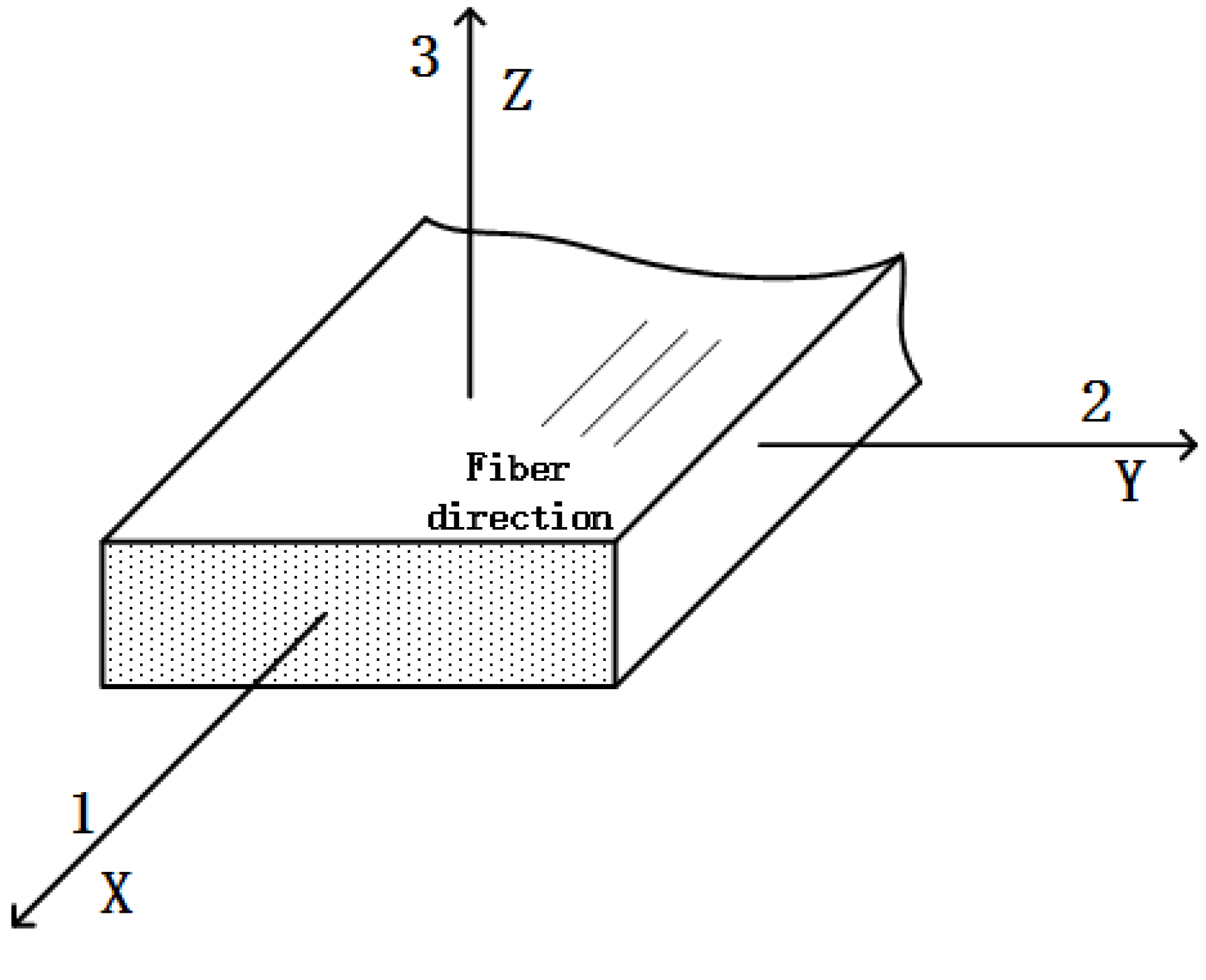
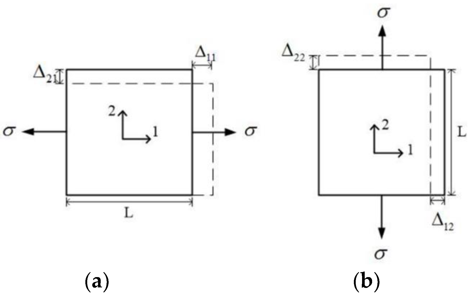
2.1. E1, E2, and ν21

The FRP laminates for structural uses in civil engineering are usually unidirectional, e.g., [44,45,46,47]. The unidirectional structural BFRP plate is generally a certain type of anisotropic material known as especially orthotropic material and can be considered as transversely isotropic material [48,49,50,51,52], as shown in Figure 1. In addition, Sections 2–3 in Figure 1 can be considered to have anisotropic material. When analyzing the micromechanical behaviors, the thickness (direction 3 in Figure 1) is quite small compared with the other two directions (directions 1 and 2 in Figure 1). Hence, the plate under tension can be subjected to the plane stress state (i.e., σ3 = τ23 = τ31 = 0). The stress-strain relationship in the plane stress state is
[ σ 1 σ 2 τ 12 ] = [ Q 11 Q 12 0 Q 12 Q 22 0 0 0 Q 33 ] [ ε 1 ε 2 γ 12 ]
where σi and εi are the stress and strain in direction i, respectively; τij and γij are shear stress and shear strain in i-j plane; Qij is the elastic constant given by
Q 11 = E 1 1 ν 12 ν 21
Q 22 = E 2 1 ν 12 ν 21
Q 12 = ν 21 E 2 1 ν 12 ν 21 = ν 12 E 1 1 ν 12 ν 21
Q 33 = G 12
in which E1, E2 and E3 are the elastic moduli in directions 1, 2 and 3, respectively; G12 is the in-plane shear modulus in plane 1–2; and ν21 and ν12 are the values of Poisson’s ratio in the two directions, as shown in Figure 2. When normal stress is applied in direction 1 (Figure 2a), the strain values can be calculated as
ε 1 = σ E 1 = Δ 11 L
ε 2 = ( ν 21 E 1 ) σ = Δ 21 L
On the other hand, the strains for the specimen subjected to a normal load at direction 2 (Figure 2b) can be calculated as
ε 2 = σ E 2 = Δ 22 L
ε 1 = ( ν 12 E 2 ) σ = Δ 12 L
As Δ12 = Δ21 for the same σ, which means the deformation in direction 2 in Figure 2a is equal to the deformation in direction 1 in Figure 2b, it can be concluded that
ν 21 E 1 = ν 12 E 2
Hence, there are in total four independent elastic parameters (i.e., E1, E2, ν21, and G12) in the plane stress problem of the orthotropic thin plates. Parameters E1, E2, and ν21 can be directly obtained from tension tests. In addition, G12 can be calculated from the derivations by the other three parameters, which are discussed in the following section.

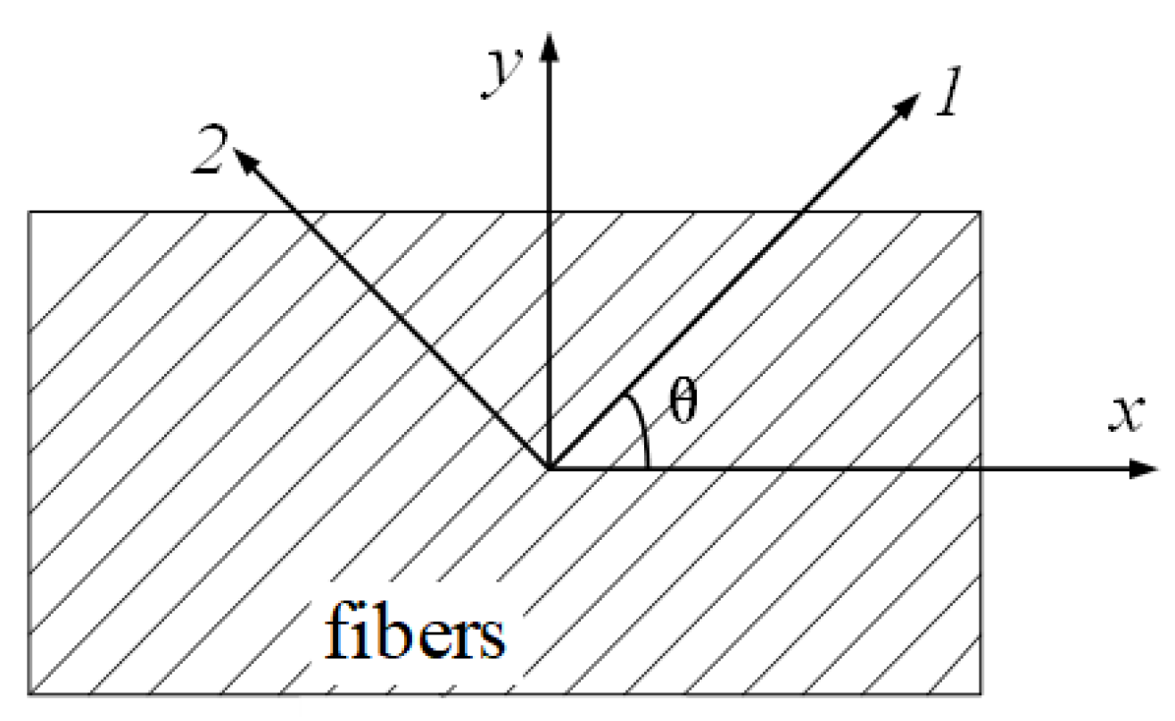
2.2. Shear Modulus G12 by the 45° Off-Axis Tension Tests

As the BFRP plate for structural uses is one type of orthotropy material, the coupling effect will cause a shear deformation when it is subjected to the asymmetric off-axis loading. A 45° off-axis tension test is an experimental method for the analysis of the shear stress field on the oblique section. It has been widely adopted to measure the shear modulus of the orthotropy material due to the ease of specimen preparation and load application. The schematic diagram of the off-axis tension test is shown in Figure 3. When the specimen is under a state of plane stress, the strain components in the x-y coordinate system of the laminate are εx, εy and γxy. The fiber direction (direction 1) has an angle of θ with the x-axis, as shown in Figure 3. The strain components in the 1–2 coordinate system (Figure 3) are ε1, ε2 and γ12. For the laminate element with dl of its diagonal length (in fiber direction), an increase in the diagonal length can be calculated as
ε 1 d l = ε x d x cos θ + ε y d y sin θ + γ x y d y cos θ
As d x = d l cos θ and d y = d l cos θ , Equation (6a) can be rewritten as
ε 1 = ε x cos 2 θ + ε y sin 2 θ + γ x y sin θ cos θ
Similarly, Equations (7) and (8) can be expressed for ε2 and γ12
ε 2 = ε x sin 2 θ + ε y cos 2 θ γ x y sin θ cos θ
γ 12 = 2 ε x sin θ cos θ + 2 ε y sin θ cos θ + γ x y ( cos 2 θ sin 2 θ )
Equations (6)–(8) can be rewritten to be the strain formula of the rotated axes:
[ ε 1 ε 2 γ 12 ] = [ cos 2 θ sin 2 θ sin θ cos θ sin 2 θ cos 2 θ sin θ cos θ 2 sin θ cos θ 2 sin θ cos θ cos 2 θ sin 2 θ ] [ ε x ε y γ x y ]
Similarly, the stress components in the 1–2 coordinate system can be calculated by
[ σ 1 σ 2 τ 12 ] = [ cos 2 θ sin 2 θ 2 sin θ cos θ sin 2 θ cos 2 θ 2 sin θ cos θ sin θ cos θ sin θ cos θ cos 2 θ sin 2 θ ] [ σ x σ y τ x y ]
When calculating the strain values by stress data, the following formula can be obtained:
[ ε 1 ε 2 γ 12 ] = [ S 11 S 12 0 S 12 S 22 0 0 0 S 66 ] [ σ 1 σ 2 τ 12 ]
where S 11 = 1 E 1 , S 12 = ν 21 E 1 , S 22 = 1 E 2 , S 66 = 1 G 12 .
For the x-y coordinate system:
[ ε x ε y γ x y ] = [ S 11 S 12 S 16 S 12 S 22 S 26 S 16 S 26 S 66 ] [ σ x σ y τ x y ]
where
1 E x = S 11 = S 11 cos 4 θ + ( 2 S 12 + S 66 ) sin 2 θ cos 2 θ + S 22 sin 4 θ = 1 E 1 cos 4 θ + ( 1 G 12 2 ν 21 E 1 ) sin 2 θ cos 2 θ + 1 E 2 sin 4 θ
ν x y E x = S 12 = S 12 ( sin 4 θ + cos 4 θ ) + ( S 11 + S 22 S 66 ) sin 2 θ cos 2 θ = ν 21 E 1 ( sin 4 θ + cos 4 θ ) + ( 1 E 1 + 1 E 2 1 G 12 ) sin 2 θ cos 2 θ
1 G x y = S 66 = 4 ( S 11 + S 22 2 S 12 1 2 S 66 ) sin 2 θ cos 2 θ + S 66 ( sin 4 θ + cos 4 θ ) = 4 ( 1 + 2 ν 21 E 1 + 1 E 2 1 2 G 12 ) sin 2 θ cos 2 θ + 1 G 12 ( sin 4 θ + cos 4 θ )
For the case of the 45° off-axis tension test, θ = 45°, σ y = τ x y = 0 , and 1 E x = 1 E 1 cos 4 θ + ( 1 G 12 2 ν 21 E 1 ) sin 2 θ cos 2 θ + 1 E 2 sin 4 θ ; therefore,
1 E 45 = ε x σ x = 1 4 [ 1 E 1 + ( 1 G 12 2 ν 21 E 1 ) + 1 E 2 ]
G 12 = 1 4 E 45 1 E 1 1 E 2 + 2 ν 21 E 1

3. Experimental Program

Based on the derivations above, the in-plane shear modulus G12 can be obtained when E1, E2, ν21 and E45 are known. And, the values of E1, E2, ν21 and E45 can be obtained by testing at different temperatures. The experimental program was presented in detail in the following sections.

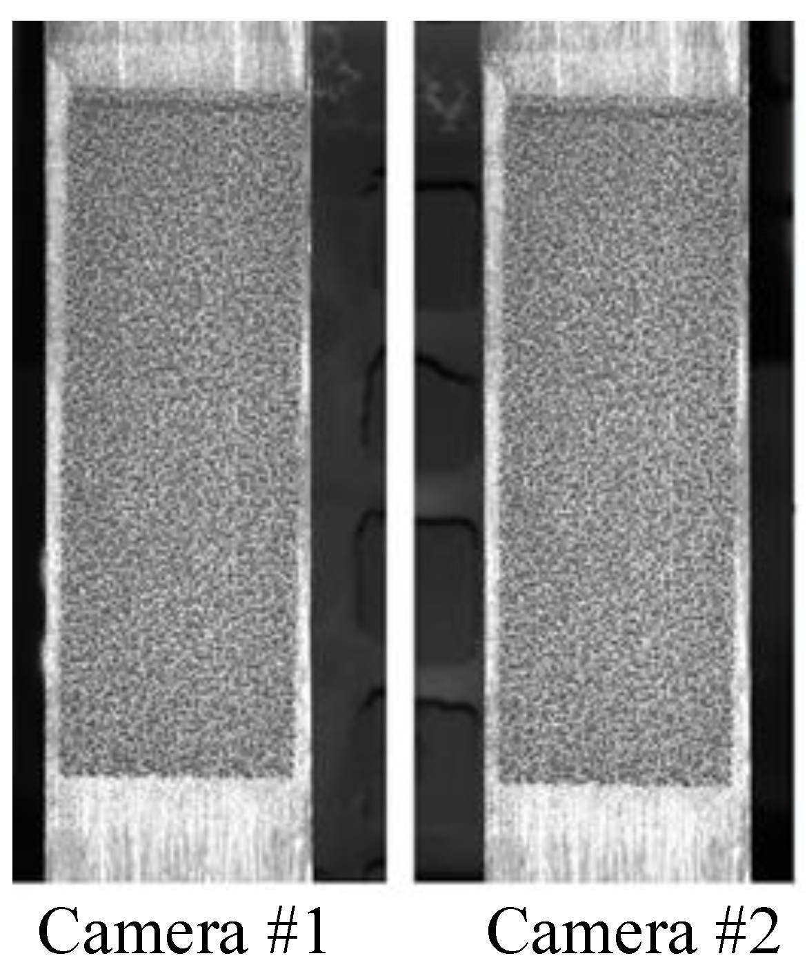
3.1. Instrumentation and Measuring System for the High-Temperature Tests

The high-temperature testing and measuring system (Figure 4), which was recently developed by the authors, consists of four subsystems: (1) a universal testing machine located in a vacuum chamber; (2) a heating system including a high-temperature vacuum pump and a high-temperature vacuum furnace with associated measuring sensors; (3) a stable lighting system with multiple green LED illuminators; and (4) a 3-D DIC sensing system (Figure 4b) including two symmetrically placed high-megapixel digital cameras and a computer. The cameras were equipped with 532 nm narrow-band filters to overcome the difficulties of surface radiation due to the high temperature and to block out ambient light. Lighting conditions also affect the quality of the speckle pattern. In the present work, a lighting system with multiple green LED illuminators and two 532 nm narrow band (10 nm) filters to block out ambient light are used to obtain the high contrast speckle pattern (Figure 4c). An image acquisition and analysis software installed on a computer was used to obtain the deformation and strain fields. Unlike the other high-temperature tests on FRP composites in the literature, the samples in this work were tested in a vacuum environment, which can provide more reliable results by avoiding the unpredicted material oxidation at high temperature. The vacuum environment also can avoid the optical refraction from hot air to room-temperature air, which can lead to inaccurate measuring results by DIC.

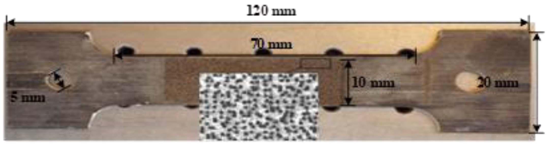
3.2. Specimen Design and Preparation
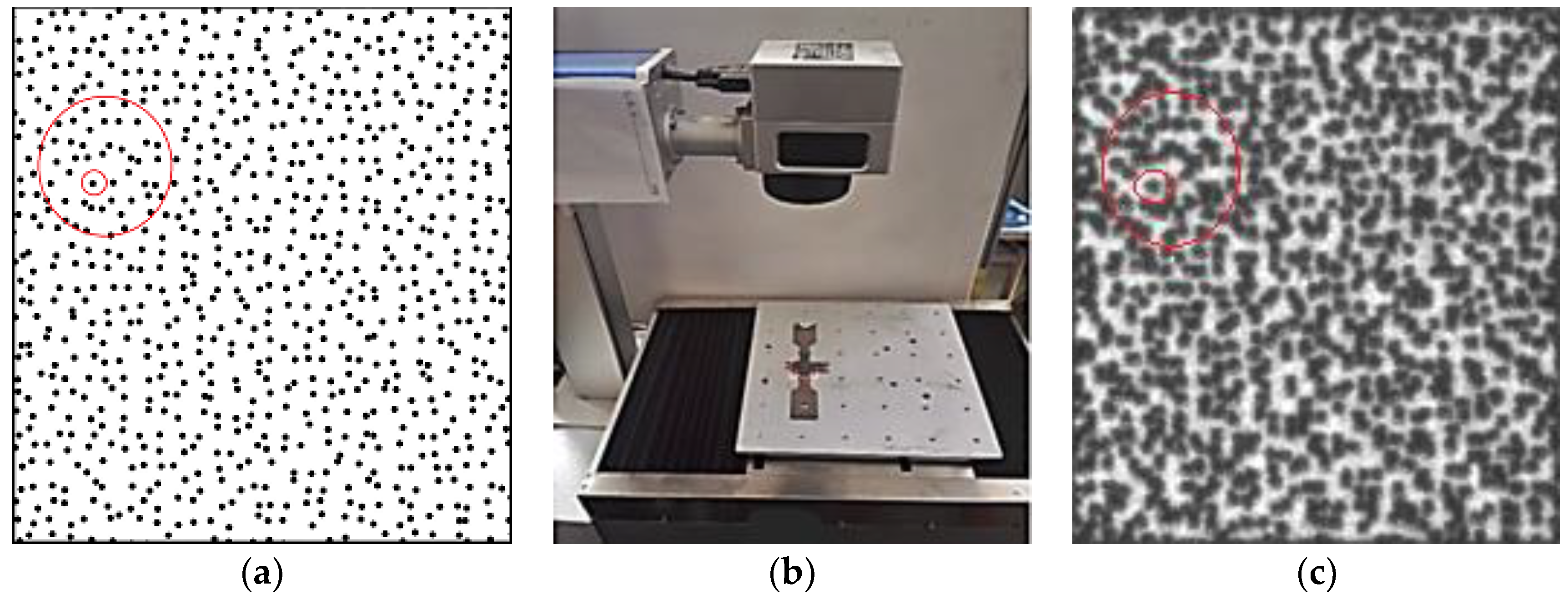
The unidirectional BFRP laminates used in this study, provided by Jiangsu Green Materials Vally New Material T&D Co., Ltd. (GMV) (Nanjing, China), had a thickness of 2 mm. The polymer matrix in this composite product was an epoxy 9804 A/B from Bluestar Wuxi Petrochemical Co, Ltd. (Wuxi, China) with 3.6 GPa, 142 N/m, 3.8, and 1.69 KJ/m for elastic modulus, fracture toughness, dielectric constant and impact strength respectively. The tested glass transition temperature of the matrix was equal to 92 °C approximately by DMA testing [53]. The fiber volume fraction of the BFRP laminates used in this work was estimated to be 56.3%. The BFRP laminates were manufactured by a pultrusion process, which leads to a very limited void fraction (as shown in Figure 5 from microscope image analysis) that can be ignored in analysis. The size of the tensile coupons was prepared according to the testing standard [54] and testing equipment, as shown in Figure 6. The specimens were designed to be tested under four different temperatures (i.e., 20 °C, 100 °C, 200 °C and 250 °C). Three different angles between loading direction and fiber direction (i.e., 0°, 45° and 90°) were investigated. Two nominally identical specimens (named 1st and 2nd in Table 1) were tested for each design, which was less than the common number of three or five but can be considered acceptable in the literature for FRP applications [55,56,57,58,59,60]. Therefore, in total, 4 (temperature levels) × 3 (loading angles) × 2 (identical specimens) = 24 specimens were carried out for tension testing in this work. The details of the tested specimens can be found in Table 1. The specimens with 0° and 90° of the load-to-fiber angle were carried out for measuring the values of E1, E2 and ν21, which are discussed in Section 2.1. The specimens with 45° of the load-to-fiber angle were prepared for the off-axis tension tests to derive the in-plane shear modulus, which is investigated in Section 2.2.
In the DIC sensing and measuring system, the specimen surfaces are usually treated by “added-on” speckle patterns such as random spraying [61,62,63,64,65,66,67]. However, such “added-on” speckle patterns tend to fail before the specimens reach the intended high temperature. To solve this problem, an engraving technique was recently developed by the authors to produce random speckle patterns directly onto the specimen surfaces [68]. The speckle patterns of various speckle sizes, densities and distributions can be generated by a specially designed fiber laser engraving system without damaging the material, as shown in Figure 7. The similarities in the red circles in Figure 7 show the consistency between the two speckling methods. The technique developed consists of the following steps:
(a)
Generate random two-dimensional coordinates of points in the X-Y plane. The density and distribution of the speckles can be controlled by computer.
(b)
Assign a radius to each speckle point, and the size of the speckles can be controlled by computer.
(c)
Generate a computer-generated speckle pattern by using the two-dimensional coordinates of random points and the radius of the speckles.
(d)
Import the computer-generated speckle pattern into the specially designed fiber laser engraving system.
(e)
By adjusting the output power and exposure time of the fiber laser engraving system, a laser-engraved speckle pattern can be created. The depth of the speckle pattern can be controlled by computer.
Therefore, the size, density and depth of the speckles can be controlled to suit a particular situation. And the pattern will never disappear until specimen failure because it is a part of the specimen. Before testing, trial tests for calibrating different speckle types (i.e., laser engraving and spraying) at room temperature were conducted. The small error on the achieved elastic modulus (approximately 3%) in Figure 8 indicates the reliability of the proposed laser engraving method. Using this testing and measuring system, the testing temperature can reach as high as 2000 °C, which can be suitable for high-temperature tests on most types of materials.

3.3. Testing

All the BFRP specimens were loaded stepwise in uniaxial tension under a displacement control of 0.1 mm/min. The gradient of heating the sample during the tests was approximately 20 °C/min. During testing, the sample surface was illuminated by a high-power LED light through a quartz glass. Two CCD cameras with 2048 × 2048 pixel resolution and two Schneider Xenoplan lenses of 1.9/35 mm were used to record the deformation field of the speckle pattern. Before applying a load, the specimen in the vacuum room was heated to the target temperature, and then the temperature was maintained for four minutes. The specimens were preloaded with 300 N and unloaded several times before loading. Because the clamping equipment in the high-temperature testing system is an interlocking type, the BFRP sample fails at the specimen ends by shear failure before the FRP rupture. This clamping method can be accepted because the aim of this work is to investigate the in-plane moduli from elastic modulus and Poisson’s ratio of the BFRP at different temperatures. The ultimate stress and strain of the BFRP at high temperature, which have been studied by others [33,35], were not necessary for the methodology in this work. Typical captured DIC images are illustrated in Figure 9.

4. Test Results and Discussion

The strain and displacement fields can be obtained from analyzing by digital signal processing (DSP) software in the DIC system. The precision of the displacement measurement can reach a magnitude of a micrometer. The typical displacement and strain fields in different directions of tested BFRP specimen are shown in Figure 10.
The width (bf) and thickness (tf) of the BFRP specimens are 10 mm and 2 mm, respectively. The tested stress values (σ) can be calculated as σ = F/(bftf). The strain values were obtained by DIC analysis. The values of elastic moduli were obtained by linear regression from the tested stress and strain values. The values of Poisson’s ratio were obtained from the strain values in two directions.
When applying the tensile stress on the BFRP specimens, the fibers were assumed to have the same deformation with the matrix with a linear stress-strain relationship, which fits σk = Eiεj (e.g., σ1 = E1ε1 or σ2 = E2ε2). If σ1 is applied on the specimen only, then the specimen can have deformations in both x and y directions with ε1 and ε2. According to the definition of Poisson’s ratio, the value of Poisson’s ratio can be determined as ν 21 = | ε 2 / ε 1 | . The stress-strain (two directions) responses of the BFRP specimens loaded in the fiber direction are illustrated in Figure 11. The values of E2 and E45 are similarly obtained by linear regression analysis from the 90° and 45° tension tests, respectively. All the values of the elastic moduli in different directions and Poisson’s ratios are listed in Table 1.
The comparison of the stress-strain relationships at different testing temperatures can be found in Figure 11e, which shows the significant degradations with the increasing temperatures. Once the values of E1, E2, ν21 and E45 are known, the in-plane shear moduli G12 of the BFRP specimens tested at different temperature levels can be calculated using Equation (13b). The calculated G12 values, as well as the average values of E1, E2, ν21 and E45, are listed in Table 2. A significant degradation of the in-plane shear modulus G12, as well as E1, E2, ν21 and E45, is illustrated in Figure 12. When the temperature is 100 °C, the in-plane shear modulus decreases to 52.2% of that at 20 °C. In addition, E1, E2 and E45 reduce to 66.3%, 55.3% and 51.7% from 20 to 100 °C, respectively. At 250 °C, E45 and G12 decrease more rapidly (with 8.7% and 3.0% of those at 20 °C, respectively) than E1 and E2.
As the glass transition temperature of the matrix in the BFRP laminates is 92 °C approximately, the composite materials at this temperature start to have significant degradations. The test results of the specimens tested at 100 °C fit this concept. The degradation due to high temperature is because of the matrix decomposition with increasing temperature. The epoxy resin becomes softer at a higher temperature. Internal debonding occurs in the fibers due to the weak adhesion of epoxy resin matrix at high temperature.

5. Conclusions

This paper presents the first study on the degradation of the in-plane shear modulus of structural BFRP laminates due to high temperature. Both analytical and experimental studied were conducted in this work. The following conclusions are drawn from the study:
(1)
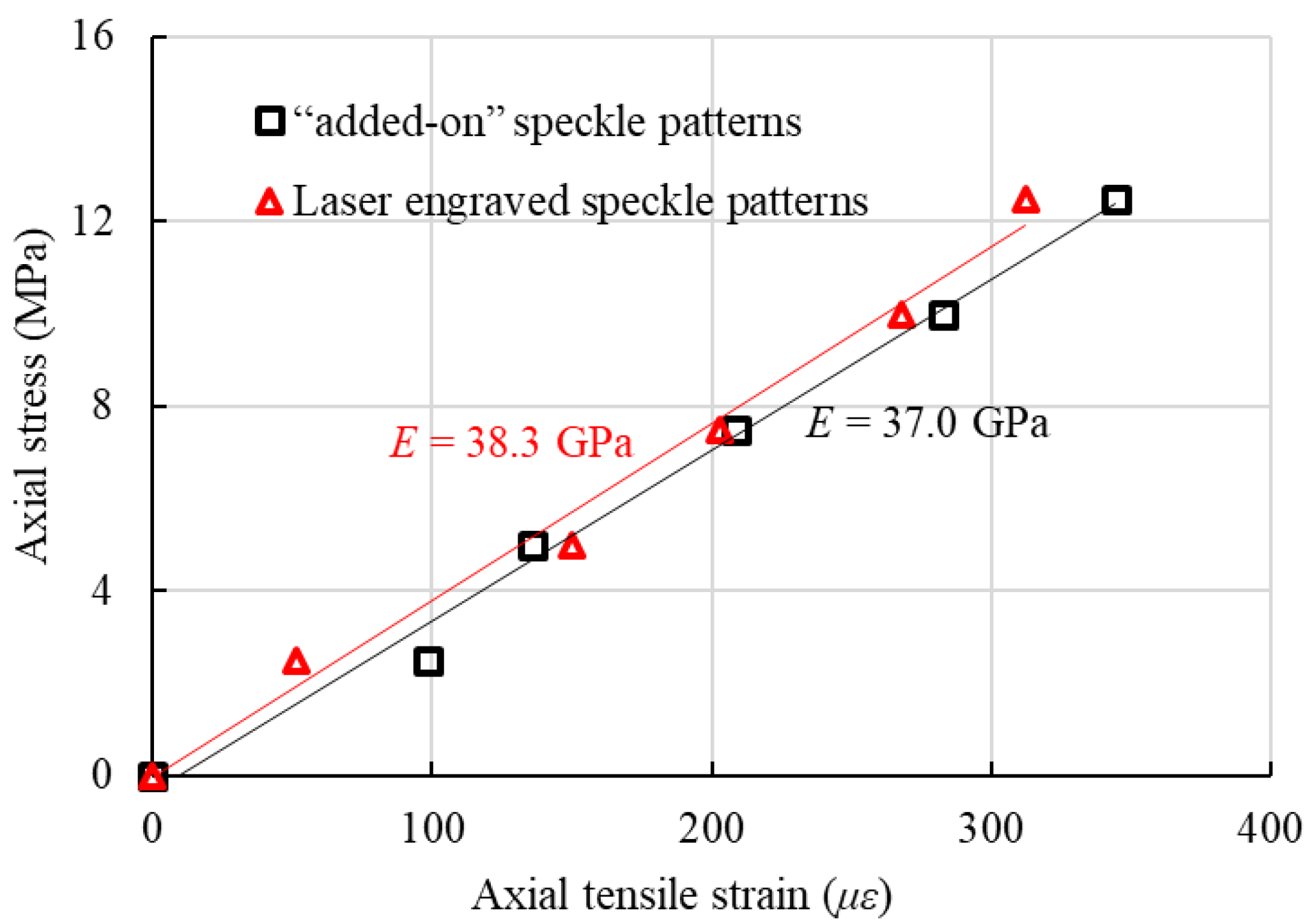
The derivations illustrated that the in-plane shear modulus can be calculated from four other mechanical parameters (i.e., E1, E2, ν21 and E45). These four parameters can be directly obtained in an experimental program including both uniaxial tension and off-axis tension tests. The newly developed testing and measuring system with DIC was successfully used to accurately measure the mechanical properties of the BFRP specimens.
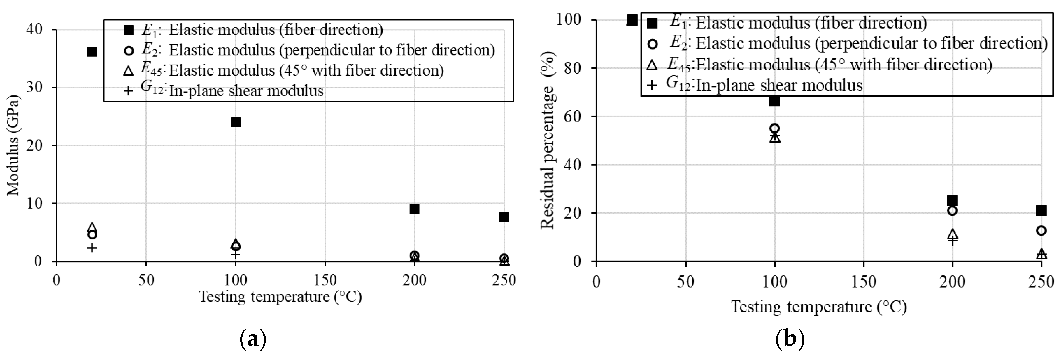
(2)
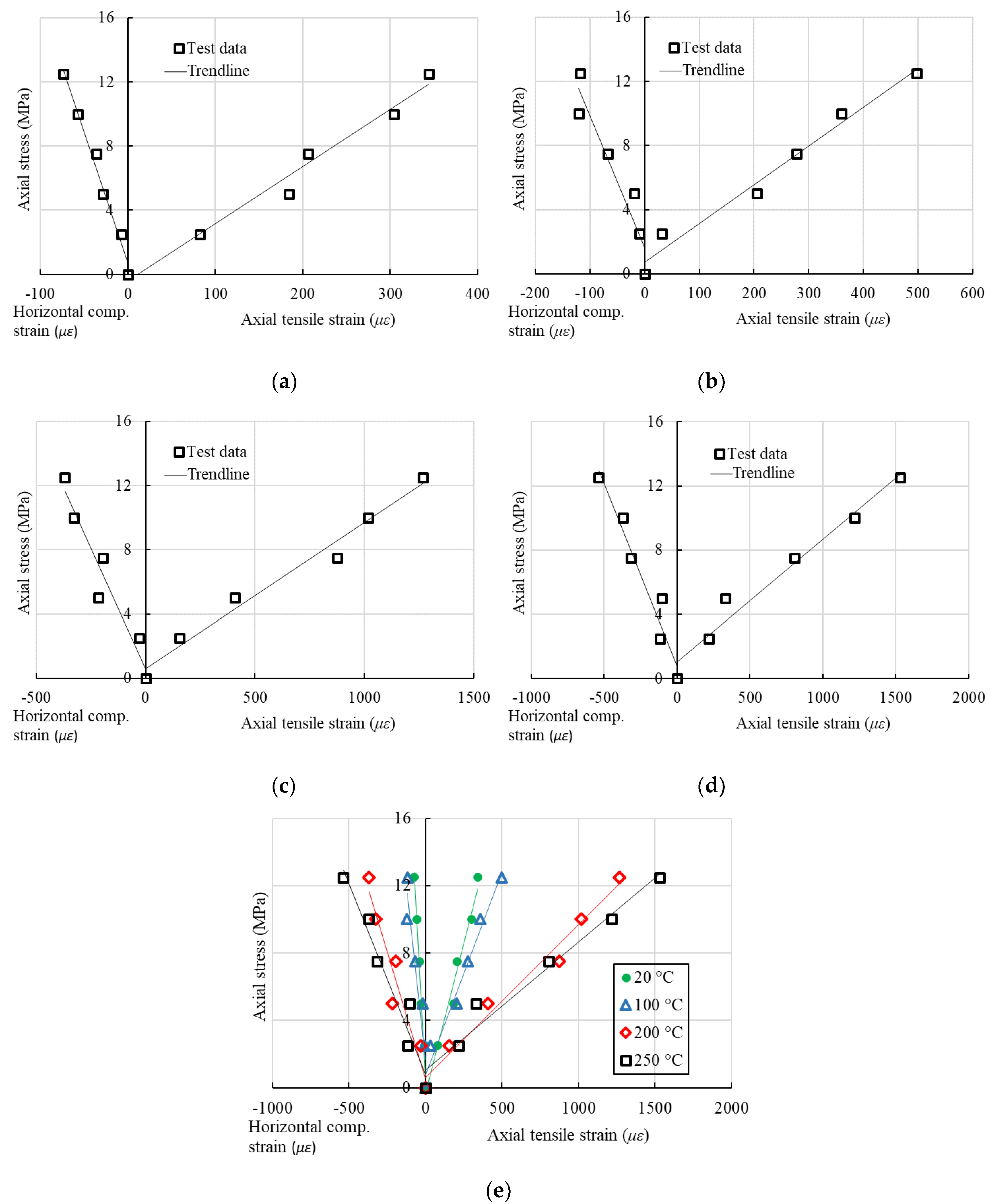
The elastic moduli of the BFRP laminates in three directions, E1, E2 and E45, from direct test results, together with the in-plane shear modulus calculated by the analytical formulas, drop to a very low level from 20 to 250 °C. The values of E45 and G12 decrease more rapidly (with 8.7% and 3.0% of those at 20 °C, respectively) than E1 and E2 at 250 °C.
(3)
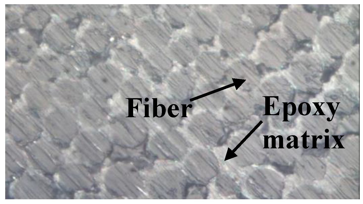
The degradation of mechanical performances due to high temperature is because of the decomposition of the epoxy resin matrix with increasing temperatures. Internal debonding occurs in the fibers due to the weak adhesion of epoxy resin matrix at high temperature.
(4)
The low level of the shear modulus, as well as other mechanical behaviors, of BFRP laminates at high temperatures show the need for the improvement on the thermal behavior for the wide applications using this composite material in the future.

Author Contributions

Conceptualization, C.J. and Y.-J.H.; Methodology, C.J. and Y.-J.H.; Experimental Investigation, Y.-J.H. and W.L.; Writing-Original Draft Preparation, C.J.; Writing-Review & Editing, Y.-J.H., Q.-Q.Y. and Y.-L.Z.; Supervision, C.J., Q.-Q.Y and Y.-L.Z.; Funding Acquisition, Y.-J.H.

Funding

This research was funded by the Shanghai Natural Science Foundation (Project No. 17ZR1419800), and the Shanghai Science and Technology Innovation Fund (Project No. 17060502600).

Acknowledgments

The BFRP plates were provided by Jiangsu Green Materials Vally New Material T&D Co., Ltd. (GMV).

Conflicts of Interest

The authors declare no conflict of interest.

References

  1. Holbery, J.; Houston, D. Natural-fiber-reinforced polymer composites in automotive applications. J. Miner. Met. Mater. Soc. 2006, 58, 80–86. [Google Scholar] [CrossRef]
  2. Dlugosch, M.; Volk, M.; Lukaszewicz, D.; Fritsch, J.; Hiermaier, S. Suitability assessments for advanced composite-metal hybrid material systems in automotive crash structural applications. Int. J. Automot. Compos. 2017, 3, 14–28. [Google Scholar] [CrossRef]
  3. Giannopoulos, I.K.; Doroni-Dawes, D.; Kourousis, K.I.; Yasaee, M. Effects of bolt torque tightening on the strength and fatigue life of airframe FRP laminate bolted joints. Compos. Part B Eng. 2017, 125, 19–26. [Google Scholar] [CrossRef]
  4. Bakis, C.E.; Bank, L.C.; Brown, V.; Cosenza, E.; Davalos, J.; Lesko, J.; Machida, A.; Rizkalla, S.; Triantafillou, T. Fiber-reinforced polymer composites for construction—State-of-the-art review. J. Compos. Constr. 2002, 6, 73–87. [Google Scholar] [CrossRef]
  5. Zhang, D.M.; Gu, X.L.; Yu, Q.Q.; Huang, H.; Wan, B.; Jiang, C. Fully probabilistic analysis of FRP-to-concrete bonded joints considering model uncertainty. Compos. Struct. 2018, 185, 786–806. [Google Scholar] [CrossRef]
  6. Jiang, C.; Yuan, F.; Wu, Y.F.; Zhao, X.M. Effect of interfacial bond on the plastic hinge length of FRP confined RC columns. J. Compos. Constr. 2019, in press. [Google Scholar]
  7. Cao, Y.G.; Wu, Y.F.; Jiang, C. Stress-strain relationship of FRP confined concrete columns under combined axial load and bending moment. Compos. Part B Eng. 2018, 134, 207–217. [Google Scholar] [CrossRef]
  8. Wan, B.; Jiang, C.; Wu, Y.F. Effect of defects in externally bonded FRP reinforced concrete. Constr. Build. Mater. 2018, 172, 63–76. [Google Scholar] [CrossRef]
  9. Jiang, C.; Wu, Y.F.; Dai, M.J. Degradation of steel-to-concrete bond due to corrosion. Constr. Build. Mater. 2018, 158, 1073–1080. [Google Scholar] [CrossRef]
  10. Qin, R.; Zhou, A.; Lau, D. Effect of reinforcement ratio on the flexural performance of hybrid FRP reinforced concrete beams. Compos. Part B Eng. 2017, 108, 200–209. [Google Scholar] [CrossRef]
  11. Ballinger, C.; Smith, W. Structural FRP composites. In Civil Engineering; American Society of Civil Engineers: Reston, VI, USA, 1990; pp. 63–65. [Google Scholar]
  12. Wu, Z.S.; Wang, X.; Wu, G. Basalt FRP composite as reinforcements in infrastructure. In Proceedings of the 17th Annual International Conference on Composites/Nano Engineering (ICCE-17), Waikiki, HI, USA, 26 July–1 August 2009; pp. 21–24. [Google Scholar]
  13. Wang, Z.; Zhao, X.L.; Xian, G.; Wu, G.; Raman, R.S.; Al-Saadi, S.; Haque, A. Long-term durability of basalt-and glass-fibre reinforced polymer (BFRP/GFRP) bars in seawater and sea sand concrete environment. Constr. Build. Mater. 2017, 139, 467–489. [Google Scholar] [CrossRef]
  14. Tang, Y.; Wu, Z.S. Distributed long-gauge optical fiber sensors based self-sensing FRP bar for concrete structure. Sensors 2016, 16, 286. [Google Scholar] [CrossRef] [PubMed]
  15. Dong, Z.; Wu, G.; Zhao, X.L.; Wang, Z.K. A refined prediction method for the long-term performance of BFRP bars serviced in field environments. Constr. Build. Mater. 2017, 155, 1072–1080. [Google Scholar] [CrossRef]
  16. Shi, J.; Wang, X.; Wu, Z.S.; Zhu, Z. Creep behavior enhancement of a basalt fiber-reinforced polymer tendon. Constr. Build. Mater. 2015, 94, 750–757. [Google Scholar] [CrossRef]
  17. Ansari, M.M.; Chakrabarti, A. Progressive damage of GFRP composite plate under ballistic impact: Experimental and numerical study. Polym. Polym. Compos. 2016, 24, 579–585. [Google Scholar] [CrossRef]
  18. Totry, E.; González, C.; LLorca, J.; Molina-Aldareguía, J.M. Mechanisms of shear deformation in fiber-reinforced polymers: Experiments and simulations. Int. J. Fract. 2009, 158, 197–209. [Google Scholar] [CrossRef]
  19. Xiang, Y.; Fang, Z.; Wang, C.; Zhang, Y.; Fang, Y. Experimental investigations on impact behavior of CFRP cables under pretension. J. Compos. Constr. 2016, 21, 04016087. [Google Scholar] [CrossRef]
  20. Zhou, A.; Tam, L.H.; Yu, Z.; Lau, D. Effect of moisture on the mechanical properties of CFRP–wood composite: An experimental and atomistic investigation. Compos. Part B Eng. 2015, 71, 63–73. [Google Scholar] [CrossRef]
  21. Yu, Q.Q.; Wu, Y.F. Fatigue durability of cracked steel beams retrofitted with high-strength materials. Constr. Build. Mater. 2017, 155, 1188–1197. [Google Scholar] [CrossRef]
  22. Wu, Y.F.; Xu, X.S.; Sun, J.B.; Jiang, C. Analytical solution for the bond strength of externally bonded reinforcement. Compos. Struct. 2012, 94, 3232–3239. [Google Scholar] [CrossRef]
  23. Cao, Y.G.; Jiang, C.; Wu, Y.F. Cross-sectional unification on the stress-strain model of concrete subjected to high passive confinement by fiber-reinforced polymer. Polymers 2016, 8, 186. [Google Scholar] [CrossRef]
  24. Bai, Y.; Keller, T.; Vallée, T. Modeling of stiffness of FRP composites under elevated and high temperatures. Compos. Sci. Technol. 2008, 68, 3099–3106. [Google Scholar] [CrossRef]
  25. Chowdhury, E.; Eedson, R.; Bisby, L.; Green, M.; Benichou, N. Mechanical characterization of fibre reinforced polymers materials at high temperature. Fire Technol. 2011, 47, 1063–1080. [Google Scholar] [CrossRef]
  26. Mahato, K.K.; Dutta, K.; Ray, B.C. High-temperature tensile behavior at different crosshead speeds during loading of glass fiber-reinforced polymer composites. J. Appl. Polym. Sci. 2017, 134, 44715. [Google Scholar] [CrossRef]
  27. Im, K.H.; Cha, C.S.; Kim, S.K.; Yang, I.Y. Effects of temperature on impact damages in CFRP composite laminates. Compos. Part B Eng. 2001, 32, 669–682. [Google Scholar] [CrossRef]
  28. Kobayashi, S.; Terada, K.; Takeda, N. Evaluation of long-term durability in high temperature resistant CFRP laminates under thermal fatigue loading. Compos. Part B Eng. 2003, 34, 753–759. [Google Scholar] [CrossRef]
  29. Cao, S.; Wu, Z.S.; Wang, X. Tensile properties of CFRP and hybrid FRP composites at elevated temperatures. J. Compos. Mater. 2009, 43, 315–330. [Google Scholar]
  30. Cao, S.; Wang, X.; Wu, Z.S. Evaluation and prediction of temperature-dependent tensile strength of unidirectional carbon fiber-reinforced polymer composites. J. Reinf. Plast. Compos. 2011, 30, 799–807. [Google Scholar]
  31. Saadatmanesh, H.; Tannous, F.E. Long-term behavior of aramid fiber reinforced plastic (AFRP) tendons. ACI Mater. J. 1999, 96, 297–305. [Google Scholar]
  32. Wei, B.; Cao, H.; Song, S. Tensile behavior contrast of basalt and glass fibers after chemical treatment. Mater. Des. 2010, 31, 4244–4250. [Google Scholar] [CrossRef]
  33. Lu, Z.; Xian, G.; Li, H. Experimental study on the mechanical properties of basalt fibres and pultruded BFRP plates at elevated temperatures. Polym. Polym. Compos. 2015, 23, 277. [Google Scholar] [CrossRef]
  34. Lu, Z.; Xian, G.; Li, H. Effects of thermal aging on the water uptake behavior of pultruded BFRP plates. Polym. Degrad. Stab. 2014, 110, 216–224. [Google Scholar] [CrossRef]
  35. Lu, Z.; Xian, G.; Li, H. Effects of elevated temperatures on the mechanical properties of basalt fibers and BFRP plates. Constr. Build. Mater. 2016, 127, 1029–1036. [Google Scholar] [CrossRef]
  36. Zhou, A.; Büyüköztürk, O.; Lau, D. Debonding of concrete-epoxy interface under the coupled effect of moisture and sustained load. Cem. Concr. Compos. 2017, 80, 287–297. [Google Scholar] [CrossRef]
  37. Wu, L.; Hoa, S.V.; Ton-That, M.T. Effects of water on the curing and properties of epoxy adhesive used for bonding FRP composite sheet to concrete. J. Appl. Polym. Sci. 2004, 92, 2261–2268. [Google Scholar] [CrossRef]
  38. Stratford, T.J.; Bisby, L.A. Effect of warm temperatures on externally bonded FRP strengthening. J. Compos. Constr. 2011, 16, 235–244. [Google Scholar] [CrossRef]
  39. Naya, F.; González, C.; Lopes, C.S.; Van der Veen, S.; Pons, F. Computational micromechanics of the transverse and shear behavior of unidirectional fiber reinforced polymers including environmental effects. Compos. Part A Appl. Sci. Manuf. 2017, 92, 146–157. [Google Scholar] [CrossRef]
  40. Mehdikhani, M.; Aravand, M.; Sabuncuoglu, B.; Callens, M.G.; Lomov, S.V.; Gorbatikh, L. Full-field strain measurements at the micro-scale in fiber-reinforced composites using digital image correlation. Compos. Struct. 2016, 140, 192–201. [Google Scholar] [CrossRef]
  41. Canal, L.P.; González, C.; Molina-Aldareguía, J.M.; Segurado, J.; LLorca, J. Application of digital image correlation at the microscale in fiber-reinforced composites. Compos. Part A Appl. Sci. Manuf. 2012, 43, 1630–1638. [Google Scholar] [CrossRef] [Green Version]
  42. Scalici, T.; Fiore, V.; Orlando, G.; Valenza, A. A DIC-based study of flexural behaviour of roving/mat/roving pultruded composites. Compos. Struct. 2015, 131, 82–89. [Google Scholar] [CrossRef]
  43. Sideridis, E. The in-plane shear modulus of fibre reinforced composites as defined by the concept of interphase. Compos. Sci. Technol. 1988, 31, 35–53. [Google Scholar] [CrossRef]
  44. Wu, Y.F.; Jiang, J.F. Effective strain of FRP for confined circular concrete columns. Compos. Struct. 2013, 95, 479–491. [Google Scholar] [CrossRef]
  45. Zheng, B.; Dawood, M. Debonding of carbon fiber–reinforced polymer patches from cracked steel elements under fatigue loading. J. Compos. Constr. 2016, 20, 04016038. [Google Scholar] [CrossRef]
  46. Ilki, A.; Peker, O.; Karamuk, E.; Demir, C.; Kumbasar, N. FRP retrofit of low and medium strength circular and rectangular reinforced concrete columns. J. Mater. Civ. Eng. 2008, 20, 169–188. [Google Scholar] [CrossRef]
  47. Nerilli, F.; Vairo, G. Experimental investigation on the debonding failure mode of basalt-based FRP sheets from concrete. Compos. Part B Eng. 2018, 153, 205–216. [Google Scholar] [CrossRef]
  48. Qiao, P.; Davalos, J.F.; Brown, B. A systematic analysis and design approach for single-span FRP deck/stringer bridges. Compos. Part B Eng. 2000, 31, 593–609. [Google Scholar] [CrossRef]
  49. Chen, J.F.; Li, S.Q.; Bisby, L.A.; Ai, J. FRP rupture strains in the split-disk test. Compos. Part B Eng. 2011, 42, 962–972. [Google Scholar] [CrossRef]
  50. Malek, A.M.; Saadatmanesh, H. Analytical study of reinforced concrete beams strengthened with web-bonded fiber reinforced plastic plates or fabrics. ACI Struct. J. 1998, 95, 343–352. [Google Scholar]
  51. Amoushahi, H.; Azhari, M. Buckling of composite FRP structural plates using the complex finite strip method. Compos. Struct. 2009, 90, 92–99. [Google Scholar] [CrossRef]
  52. Maimi, P.; Mayugo, J.A.; Camanho, P.P. A three-dimensional damage model for transversely isotropic composite laminates. J. Compos. Mater. 2008, 42, 2717–2745. [Google Scholar] [CrossRef]
  53. Zhao, X.; Wang, X.; Wu, Z.S.; Keller, T.; Vassilopoulos, A.P. Temperature effect on fatigue behavior of basalt fiber-reinforced polymer composites. Polym. Compos. 2018, in press. [Google Scholar] [CrossRef]
  54. Standardization Administration of China. GB/T 1447-2005. Fiber-Reinforced Plastics Composites—Determination of Tensile Properties; Standardization Administration of China: Beijing, China, 2005.
  55. Wu, Y.F.; Jiang, C. Effect of load eccentricity on the stress–strain relationship of FRP-confined concrete columns. Compos. Struct. 2013, 98, 228–241. [Google Scholar] [CrossRef]
  56. Nanni, A.; Bradford, N.M. FRP jacketed concrete under uniaxial compression. Constr. Build. Mater. 1995, 9, 115–124. [Google Scholar] [CrossRef]
  57. Ozbakkaloglu, T.; Akin, E. Behavior of FRP-confined normal-and high-strength concrete under cyclic axial compression. J. Compos. Constr. 2011, 16, 451–463. [Google Scholar] [CrossRef]
  58. Li, P.; Wu, Y.F.; Gravina, R. Cyclic response of FRP-confined concrete with post-peak strain softening behavior. Constr. Build. Mater. 2016, 123, 814–828. [Google Scholar] [CrossRef]
  59. Li, P.; Wu, Y.F. Stress–strain behavior of actively and passively confined concrete under cyclic axial load. Compos. Struct. 2016, 149, 369–384. [Google Scholar] [CrossRef]
  60. Zhou, A.; Qin, R.; Feo, L.; Penna, R.; Lau, D. Investigation on interfacial defect criticality of FRP-bonded concrete beams. Compos. Part B Eng. 2017, 113, 80–90. [Google Scholar] [CrossRef]
  61. Jiang, C.; Wu, Y.F.; Wu, G. Plastic hinge length of FRP-confined square RC columns. J. Compos. Constr. 2014, 18, 04014003. [Google Scholar] [CrossRef]
  62. Wu, Y.F.; Jiang, C. Quantification of bond-slip relationship for externally bonded FRP-to-concrete joints. J. Compos. Constr. 2013, 17, 673–686. [Google Scholar] [CrossRef]
  63. Guan, D.; Jiang, C.; Guo, Z.; Ge, H. Development and seismic behavior of precast concrete beam-to-column connections. J. Earthq. Eng. 2018, 22, 234–256. [Google Scholar] [CrossRef]
  64. Yu, Q.Q.; Wu, Y.F. Fatigue Strengthening of Cracked steel beams with different configurations and materials. J. Compos. Constr. 2016, 21, 04016093. [Google Scholar] [CrossRef]
  65. Jiang, C.; Wu, Y.F.; Jiang, J.F. Effect of aggregate size on stress-strain behavior of concrete confined by fiber composites. Compos. Struct. 2017, 168, 851–862. [Google Scholar] [CrossRef]
  66. Guan, D.; Guo, Z.; Jiang, C.; Yang, S.; Yang, H. Experimental evaluation of precast concrete beam-column connections with high-strength steel rebars. KSCE J. Civ. Eng. 2018, in press. [Google Scholar]
  67. Dong, Y.L.; Pan, B. A review of speckle pattern fabrication and assessment for digital image correlation. Exp. Mech. 2017, 57, 1161–1181. [Google Scholar] [CrossRef]
  68. Hu, Y.J.; Wang, Y.J.; Cheng, J.B.; Zhu, J.M. A new method of creating high-temperature speckle patterns and its application to the determination of high temperature mechanical properties of metals. Exp. Tech. 2018, in press. [Google Scholar] [CrossRef]
Figure 1. The schematic diagram of the BFRP plate.
Sensors 18 03361 g001
Figure 2. Deformation in plane 1–2. (a) Loading on axis 1, (b) Loading on axis 2.
Sensors 18 03361 g002
Figure 3. Schematic diagram of the off-axis tension tests.
Sensors 18 03361 g003
Figure 4. High-temperature testing and measuring system. (a) Test setup, (b) DIC sensing system, (c) lighting system.
Sensors 18 03361 g004
Figure 5. Typical microscope image of a BFRP laminate section.
Sensors 18 03361 g005
Figure 6. Tensile coupon specimen.
Sensors 18 03361 g006
Figure 7. Laser engraving machine and engraved speckles: (a) computer-generated speckle pattern, (b) laser engraving system, and (c) laser engraved speckle pattern based on the computer input.
Sensors 18 03361 g007
Figure 8. Test results for the BFRP samples with different speckle types.
Sensors 18 03361 g008
Figure 9. Captured DIC images when testing.
Sensors 18 03361 g009
Figure 10. Typical DIC results at a tensile load of 300 N and 250 °C. (a) Vertical displacement field (fiber direction), (b) Horizontal displacement field (perpendicular to the fiber direction), (c) Vertical strain field and (d) Horizontal strain field.
Sensors 18 03361 g010
Figure 11. Stress-strain response of the BFRP specimens loaded in the x-direction (1st group). (a) Test at 20 °C, (b) Test at 100 °C, (c) Test at 200 °C, (d) Test at 250 °C, (e) Comparison.
Sensors 18 03361 g011
Figure 12. Degradation of the BFRP modulus due to high temperature. (a) Values of the different moduli, (b) Residual percentages of the different moduli.
Sensors 18 03361 g012
Table 1. Details of the tested specimens.
Temperature (°C)Load-to-Fiber AngleSpecimen IDν21E1 (GPa)E2 (GPa)E45 (GPa)
201st0.21535.532--
2nd0.24936.955--
90°1st--4.819-
90°2nd--4.531-
45°1st---5.767
45°2nd---6.244
Standard deviation0.0241.0060.2040.337
1001st0.27224.148--
2nd0.28423.760--
90°1st--2.778-
90°2nd--2.358-
45°1st---3.223
45°2nd---3.056
Standard deviation0.0080.2740.2970.118
2001st0.3209.091--
2nd0.30910.397--
90°1st--0.962-
90°2nd--1.056-
45°1st---0.683
45°2nd---0.770
Standard deviation0.0080.9230.0660.062
2501st0.3357. 622--
2nd0.3247. 804--
90°1st--0.639-
90°2nd--0.604-
45°1st---0.225
45°2nd---0.262
Standard deviation0.0080.1290.0250.026
Table 2. Summary of the test results (average values).
Temperature (°C)ν21E1 (GPa)E2 (GPa)E45 (GPa)G12 (GPa)
200.2336.24.76.02.3
1000.2824.02.63.11.2
2000.319.11.00.70.2
2500.337.70.60.20.07

