1. Introduction
In fifth generation (5G) wireless networks, one main expectation is to enhance energy efficiency significantly in comparison with previous generation networks. However, a large number of devices will be connected in future wireless networks where challenges with the explosion of mobile internet applications and Internet of things (IoT) services will be met. In addition, big concerns are highlighted as critical environmental issues, i.e., high carbon emissions. Therefore, such mass connections will unavoidably give rising global energy consumption with an unprecedented surge. Hence, green communication needs to be established to improve the network energy effectiveness. Inspired from advantages of various energy harvesting (EH) architectures, relaying network is proposed to provide information transmission and energy-transmission cooperation and it has now been suggested to improve the overall energy efficiency [
1,
2,
3]. The popular energy resources in EH including solar and wind, which are intermittent under impacts the environmental alteration. Among the emerging technologies, radio-frequency (RF) signals have been regarded as viable new sources for EH. In [
1,
2], it was shown that RF EH can exhibit outage performance as introducing the energy efficiency of the wireless relaying networks. Furthermore, due to the dual properties of RF, namely information transmission and EH, an emerging technique termed as simultaneous wireless information and power transfer (SWIPT) has attracted increasing attention [
3,
4,
5,
6]. The authors in [
3] first proposed power splitting and time switching schemes to wireless power transfer from the source to relay to guarantee operation of the second hop in dual-hop relaying network. More importantly, outage probability and ergodic capacity are popular metrics to evaluate system performance. The authors in [
4] investigated SWIPT over deploying new energy harvesting originated from co-channel interference. Similar trend to explore SWIPT more is that tractable form of derived expressions for performance analysis [
5] and then extended work can be reported in [
6] into a practical imperfect channel state information (CSI) to consider optimal policy regrading instantaneous rate. The impact of energy harvesting on performance of relaying policies regarding scenario of fixed power allocation and cognitive radio is considered and such a model is deployed with simultaneous wireless information and power transfer [
7].
Recently, non-orthogonal multiple access (NOMA) has been suggested to adapt the explosive progress of mobile Internet regarding data traffic volume [
8,
9,
10]. To realize higher spectral effectiveness than conventional orthogonal multiple access, i.e., orthogonal frequency division multiple access (OFDMA), both successive interference cancelation (SIC) and superposition coding scheme are applied respectively at the transmitters and the receivers in NOMA. Besides, in the same frequency or time resources, NOMA’s users can more connections can be supported by allowing simultaneously access [
11,
12,
13,
14]. Consequently, the next generation of mobile communication systems can deploy NOMA as a favorable multiple access scheme for [
15,
16,
17]. In addition, by splitting them in the power domain and in the same frequency band and time slot, multiple users in NOMA can be simultaneously served [
18]. The authors in [
19] presented basic concept of NOMA together with SIC receiver scheme. Considering the case of fixed power allocation, the authors in [
20] investigated ergodic sum rate and the outage performance for NOMA.
In another line of research, the existing advanced schemes such as multiple-input multiple-output (MIMO) can be included in NOMA as an attractive property in research about NOMA [
21]. In a different system model, NOMA is studied in cooperative relaying networks (CRS) [
22], heterogeneous system [
23], and device-to-device (D2D) networks with full-duplex scheme [
24]. In another trend, the cooperative NOMA (C-NOMA) together with CRS as investigation in [
24] in which spatially multiplexed scheme to serve a single user.
Motivated by these discussions, in this paper we propose and analyse a relaying wireless sensor system with WPT under collecting energy from an external energy resource. Our results show that the TPSR factor and the transmission power at the relay should be jointly designed to achieve an optimal ergodic throughput efficiency, and system performance in NOMA outperforms than orthogonal multiple access (OMA) as investigations in the literature [
20]. The main contributions of this paper can be shown as:
Different with system model and mathematical analysis reported in [
7], the new architecture related to EH (namely EH-NOMA protocol) is investigated and the impact of energy-aware fractions on wireless sensor system performance are studied. Such system model is designed as a combination of the two traditional EH receivers time switching based relay (TSR) and power splitting based relay (PSR) [
3] in unique protocol, namely TPSR [
25]. Although, we analysed system performance for OMA based network in [
25] but this paper is extended work to highlight performance in NOMA scenario.
We derive some analytical expressions of cumulative distribution function (CDF) of signal-to-noise ratio (SNR) and then outage probability is derived for system evaluation with considerations of power allocation factors in EH-NOMA protocol applied at the relay.
The ergodic rate is derived to evaluate ergodic performance of such EH-NOMA protocol where energy harvesting-aware fractions are chosen reasonably to achieve better performance.
To highlight advantages of NOMA, the traditional OMA and non-energy harvesting situation are presented. Such comparison can be observed in simulation results to confirm our analytical expressions.
Next, Monte Carlo simulations are presented the outage performance to corroborate our analysis and the impact of some significant parameters on proposed protocol in EH-assisted networks are investigated.
The remainder of this paper is organized as follows:
Section 2 presents the system model and TPSR protocol deployed in NOMA assisted wireless sensor system is investigated. In
Section 3, we derive the analytical expressions of outage probability and ergodic throughput in delay-tolerant transmission.
Section 4 examines the simulation results. Finally,
Section 5 completes with conclusion remarks for the paper and reviews the important results.
Notation: Throughout this paper, denotes probability, and symbolize the cumulative distribution function (CDF) and the probability density function (PDF) of a random variable Z, respectively, and indicates the expectation operator.
2. System Model
We consider cooperative AF relaying wireless sensor network, where the source
communicates with two destinations
through an intermediate relay
.
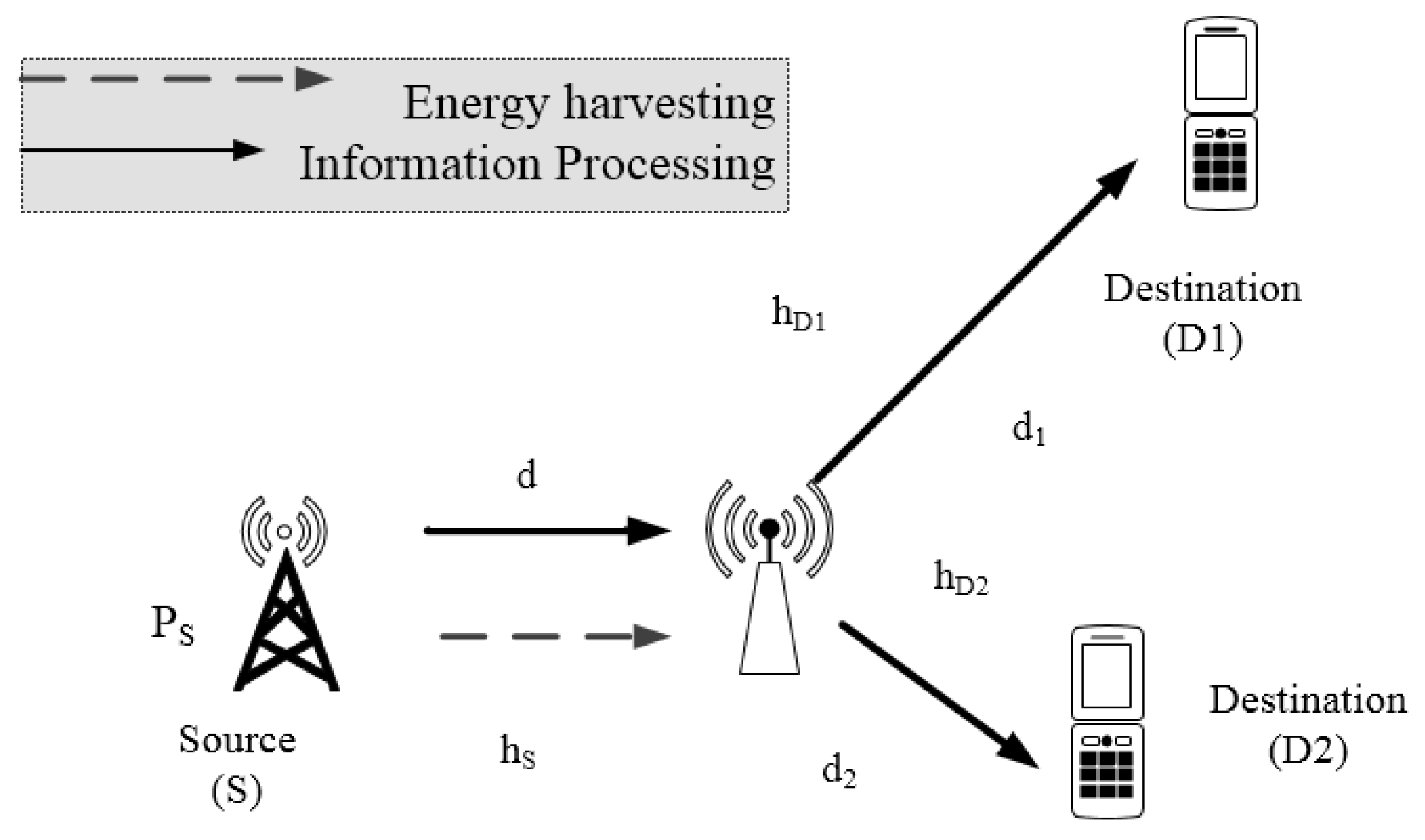
Figure 1 shows relay scheme to source node can be served two far devices or sensor by requiring help of wireless powered relay. It is worth pointing out that these considered models can be deployed in wireless sensor or mobile network. The link between the source and the destination is unreliable or unavailable, so the transmission can only happen successfully with the aid of the wirelessly powered relay. In particular, the relay node deployed in this paper is characterized as energy-constrained node. Furthermore, each node is furnished with a single antenna, and half-duplex mode using amplify-and-forward (AF) strategy is deployed in the relay. We call
are distances between source and relay and relay to
D1,
D2 respectively;
m is path loss coefficients. The relay acquires two independent data symbols during two time epochs,
and
transmitted from
S directly and such signal processing need assistance of the relay, whereas the EH-NOMA relay delivers data symbol with harvested power.
Ernergy harvesting protocol for such NOMA scheme is time power based relaying energy harvesting (TPSR) protocol as recent investigation in [
25]. In particular, during the first phase
S broadcasts a superposition-coded signal
(i.e., it equals to
) to the relay (i.e.,
R) and the destination
, where
represents the total transmit power of the source
S, and
symbolizes the power allocation quantity for symbol
respectively. The superimposed signal will be detached at destination for separated services in NOMA users, and without of generality it can be assumed
to satisfy condition
. Due to similar performance at
, we assume that the following consideration aims to evaluate at (
D1). We denote
as channel between relay and (
D1). The channel gains between the nodes are modeled as
and two channels to
D1 and
D2 are assumed as the same average gains
due to
D1,
D2 belong to one group of NOMA users, and assuming that all channels follow flat fading Rayleigh distribution.
During the first phase, the received signals at the relay is given by:
where
stands for antenna noise,
is complex additive white Gaussian noise (AWGN) at relay due to signal RF converting to base band signal. Using Amplify-and-Forward (AF) scheme, the relay will be amplified with factor
G as given by:
After signal processing at relay, in the second phase the relay amplifies the received signal to forward to destination with power as
, this power depends on harvested power in first phase. In such model, the role of
D1 and
D2 is similar, we only consider on performance of
D1. The received signal at destination
D1 denoted as
given by:
where
and
are respectively white Gaussian noise (AWGN) at destination and converting operation to base band from RF signal at destination
D1. Plugging
and
G from (
1) and (
2) into (
3),
can be expressed as:
We denote
and
as overall noise AWGN at the relay and destination. Therefore,
is total variance noise AWGN at relay in TPSR. The harvested energy for signal processing at relay in energy harvesting phase denoted as
re-used in next signal processing
and hence the transmit power at relay can be computed as:
By replacing
from (
5) into (
4), the received signal at destination
D1
can be given by:
3. Outage Performance and Ergodic Capacity Analysis
We first determine the signal to noise ratio (SNR) as the following section, and then we perform outage probability and then ergodic capacity is derived. Such outage event is evaluated as probability to the following system rate less than the pre-defined threshold rate
, i.e.,
:
In particular, the end-to-end SNR can be computed by:
where
stands for expectation operation. In this study, we denote AWGN noise terms at
D1,
D2 are the same, and equal to
. In principle of NOMA, the successive interference cancellation (SIC) will be implemented at each user in dedicated group to decode at each user and separate superimposed symbols and traditional OMA can mitigate the inter-user interference as well. At destination
D1, the considered user first consider
D2’s signal as noise to detect its own signal, while SIC is deployed at
D2 to help detection of
D2’ signal. In order to realize a stable trade-off between system throughput and user fairness, it is known that assigning less transmit power for users with better channel conditions and greater transmit power for users with worse channel conditions. In NOMA, the coding order is determined based on QoS requirement.
Without loss of generality, we further assume that following the principle of NOMA, the users’ power allocation coefficients are ordered as
[
26]. In general, in order to ensure the performance of NOMA systems, the NOMA-strong user (i.e.,
D1) is allocated less power than the NOMA weak user (i.e.,
D2). As a result, it can be obtained specific SNR for detect
D1’ signal at
D1 as:
where
The simple form of (9) needs to be derived for the next calculation. The reason for simplify above expression is that small component can be eliminated, i.e.,
at high SNR regime. As a result, at high SNR, the received SNR for detecting symbols
at the destination D1 in approximate value can be given as:
Different with decoding operation in
D1, it is worth noting that at
D2 noise firstly needs to be eliminated. In this case, the signal of
D1 is considered as noise. As a result, the received SNR for detect noise term
at
D2 given by:
where
.
Following principle of NOMA, after SIC operation occurs at destination
D2, the receiving SNR for detecting
is given by:
3.1. Outage Probability
The following consideration provides an exact expression for the outage probability achieved by the two-stage AF relay in the proposed EH-NOMA. More importantly, the outage probability for such EH-NOMA with the proposed TPSR relaying scheme for
D1,
D2 are respectively calculated. For
D1’ signal, an outage event for
can be interpreted by main reason, i.e., it cannot detect its own message. For
D2’ signal, the outage would happen for
in two cases where
D2 can not detect
D1’s information and also can not recover its own information [
26]. It is noted that in this paper direct link is not considered, then outage expressions are simpler than that in [
26]. Such outage events for
D1 and
D2 can be given respectively by:
In special case at high SNR, it can be shown the closed-form expression of remaining outage probabilities can be computed by applying following Lemma 1.
Lemma 1. We denote and The outage expression corresponding the threshold SNR γ can be expressed by: As a result, it can be solved in closed-form by:where is first order Bessel function. Proposition 1. The outage probability for D1 in EH-NOMA system given by:where , and are defined similarly in Lemma 1. Proof of Proposition 1. Applying Lemma 1, it can be obtained outage event
in (
13) as below:
with
,
, and
are defined below Proposition 1. This is the end of the proof. □
Proposition 2. The outage probability for D2 in EH-NOMA system given by:where , , , and are defined similarly below Lemma 1. Proof Proposition 2. Applying result from Lemma 1 and related formula, it is easy to obtain the final expression of
in (
13)
and
can be obtained by:
In similar way, the separated outage probability,
, can be computed by:
where
,
,
and
are defined below proposition 2. Replacing
and
into (
13), Proposition 2 is determined. This ends the proof. □
Remark 1. It hard to derive optimal time switching and power splitting factor to achieve best outage performance as in (16) and (18). In fact, several algorithms are proposed to determine optimal throughput. However, time consuming for such computation exhibits to delay and hence system performance will be worse than the usual case. As a result, this paper only considers a couple of energy harvesting parameters in simulation to evaluate where the optimal scenario can be obtained. 3.2. Ergodic Capacity
The achievable ergodic capacity of the proposed EH-NOMA system is examined, and we have the following key result. In this section, the ergodic achievable rate of
at
D1 can be readily calculated as:
It is can be rewritten as below [
3]:
in which
,
Proposition 3. The ergodic capacity at the D1 for the TPSR protocol is given by:where Similarly, the ergodic achievable rate of for D2 can be considered as: To the best of the authors’ knowledge, the ergodic rate for D2 does not admit a closed-form expression. As a result, in case of high SNR, it can be obtained the closed-form as below.
Proposition 4. The ergodic capacity at the D2 for the TPSR protocol is calculated by:and it is shown in closed-form as: 3.3. Non-Energy Harvesting (NEH) as a Benchmark
We first denote
as SNR at transmitter. Similarly with energy harvesting case, the outage probability of
D1 in NEH case is given by:
Then the outage probability of
D2 in NEH case is expressed by:
In which, it can be shown that:
Remark 2. In this NEH case, the relay obtains higher power compared wireless power as EH case, then outage performance is expected to improve. It is hard to confirm it in such formula, but we can check via simulation as presentation in next section.
4. Simulation Results
Unless otherwise stated, regarding on energy harvesting protocol, i.e., energy harvesting efficiency is set by , source transmission power, (Joules/sec), and path loss exponent (which corresponds to an urban cellular network environment ). To perform the above outage events, separated probability components must be calculated. For simplicity, we assume that at the fixed rate R. In practice, different rates are assigned for different users, but in this study we set the source transmission rate, R = 1 (bits/sec/Hz) in the delay limited transmission mode for simple analysis. The distances d, and are normalized to unit value. For simplicity, similar noise variances at the relay and the destination nodes are assumed, i.e., different kinds of noise variance is set as . Power allocation factors for NOMA except to specific simulation results. The mean values, of the exponential random variables , respectively, are set to 1.
Figure 2 plots the outage probability for cooperative NOMA with different power allocation factors for AF relaying, where energy harvesting fractions contribute to change outage performance shown as different curves. Observing the
Figure 2, one can conclude that compared among three cases of EH-NOMA with AF relaying, the proposed scheme with higher time switching fraction allocation for energy harvesting can realize better outage performance as fixed power splitting factor is used. Furthermore,
Figure 2 manifests that EH-NOMA can remarkably enhance the outage performance at high transmit power at source
. More importantly, the analytical curves match very well with Monte-Carlo results. While
Figure 3 illustrates outage performance at
D1 as varying power splitting factor. As can be seen clearly, increasing power splitting factor leads to better outage performance in case of fixed time switching fraction.
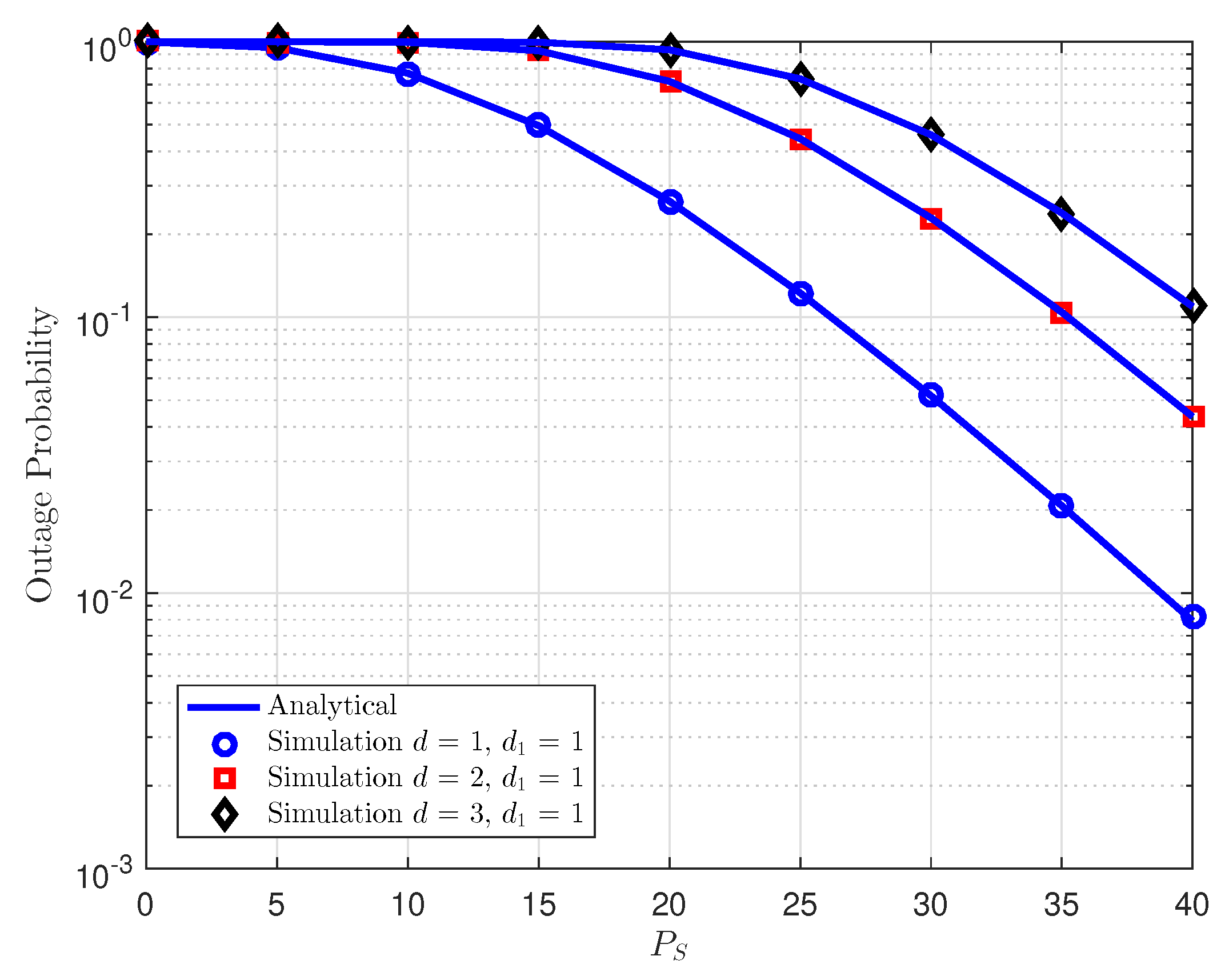
In
Figure 4, by changing the relay location, it can be seen the outage performance will be affected by such parameter. Note that two users have different optimal locations. Since the source in NOMA assigns transmit power to the users, the ideal relay location for the user can impact system performance. In this case, as the relay locates far from the source the performance gets worse.
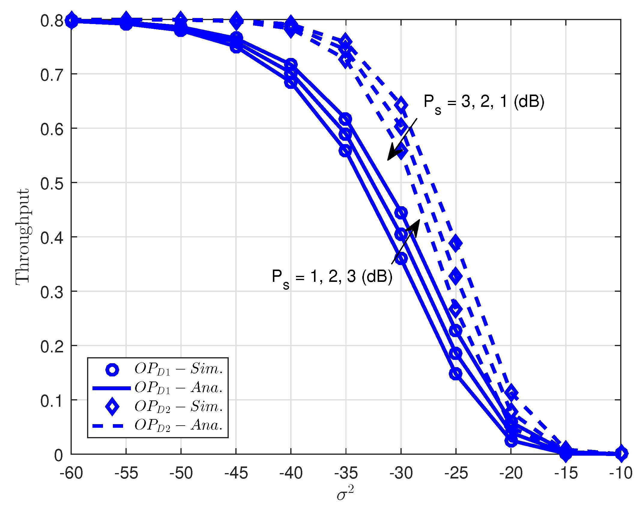
As can be seen in
Figure 5, it shows the optimal throughput versus changing variance noise term in EH-NOMA in case of changing transmit power at source. It is noted that throughput can be shown as
corresponding fixed rate
R. As can be seen clearly, the proposed scheme with higher transmit power (
can realize better throughput performance due to more energy for signal processing. It is noted that noise term contributes to lowest throughput, especially at high noise −20 to −10 dB. In such a scenario, the outage probability of
D2 outperforms the outage probability at
D1. The reason is that more power allocated for
D2 as principle of NOMA as concern before.
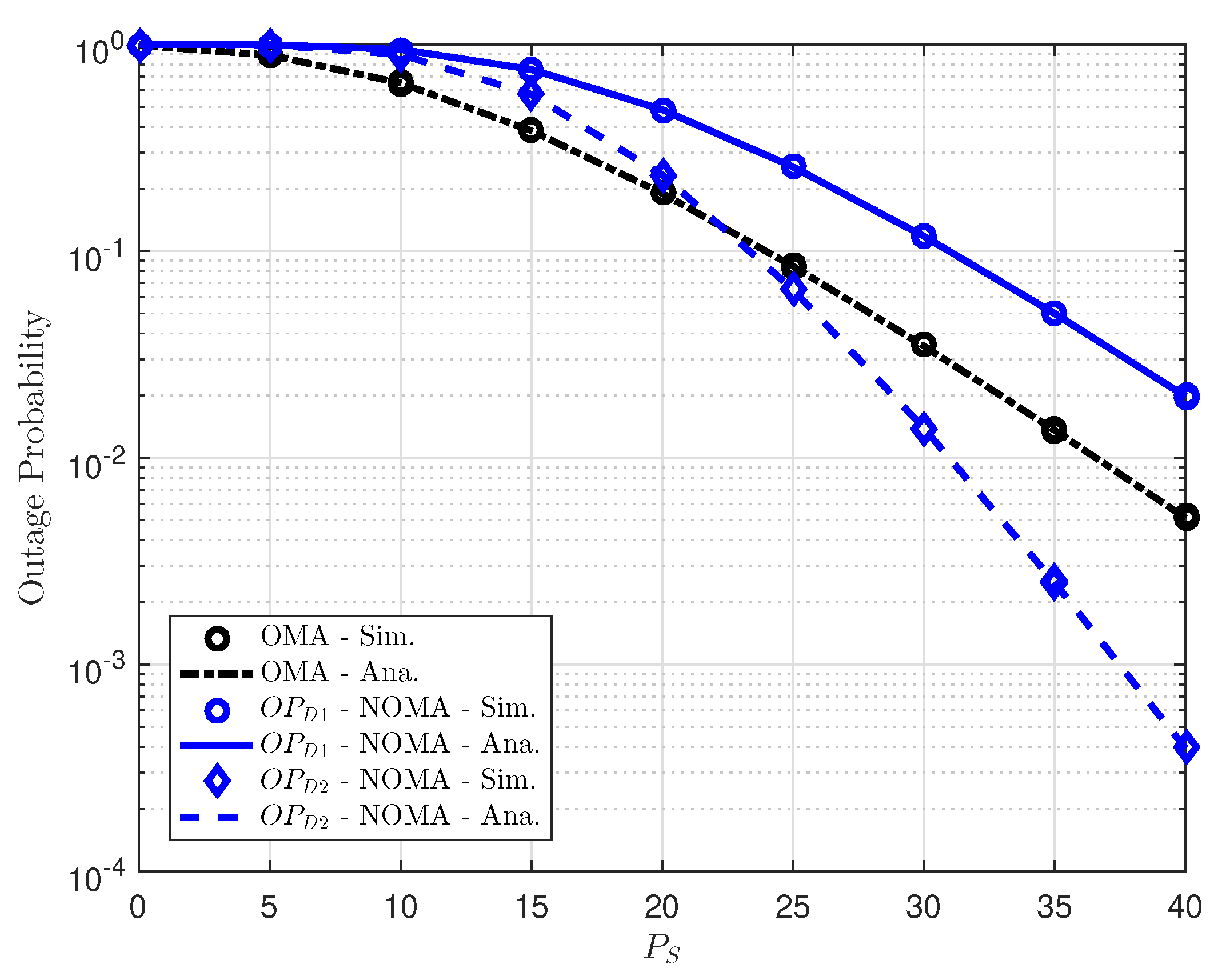
In
Figure 6, we compare the outage performance for EH-NOMA with OMA scheme by using different users’ target rates and different numbers of relays. It can be observed from such experiment that OMA relaying schemes can achieve better outage performance than user
D1 in NOMA scheme, but it is worse than outage performance of
D2. Furthermore, we can also see that the outage performance in
D2 of NOMA is significantly enhanced with high transmit power at source. In addition,
Figure 6 also demonstrates that energy harvesting remains continuous operation of relay where has signal processing and outage performance at acceptable as reasonable selection of related parameters as in simulation result.
To evaluate system performance with NEH case, we illustrate outage performance on dedicated NEH situation as varying power allocation as in
Figure 7. It can be seen that more power allocated to user
D2 and higher outage performance can be achieved in the case that relay furnishes individual power (without energy harvesting). It is more important to perform such comparison in
Figure 8, it compares EH case and NEH case, where NEH can be outperform than EH case due to higher amount power at relay used to transmit signal to
D1 and
D2. It is a consistent result with several experiments reported in [
3,
4,
5,
6].
Figure 9 and
Figure 10 present the ergodic capacity versus transmit power at source with different power allocation factors in NOMA for each user. One can observe that
D1 obtains the highest throughput since it has the higher power assigned among two users. We continue to study the ergodic performance versus the transmit SNR in
Figure 8 and the power allocation factors are changed to evaluate its impacts. It can be seen clearly that increasing the transmit power can improve the ergodic capacity (throughput). The figure also demonstrates the existence of the throughput ceilings in the high transmit power
region. This is due to the fact that the outage probability is approaching zero and the ergodic capacity is determined only by the targeted data rate. It can be confirmed that the analytic result that is obtained as previous section is valid.
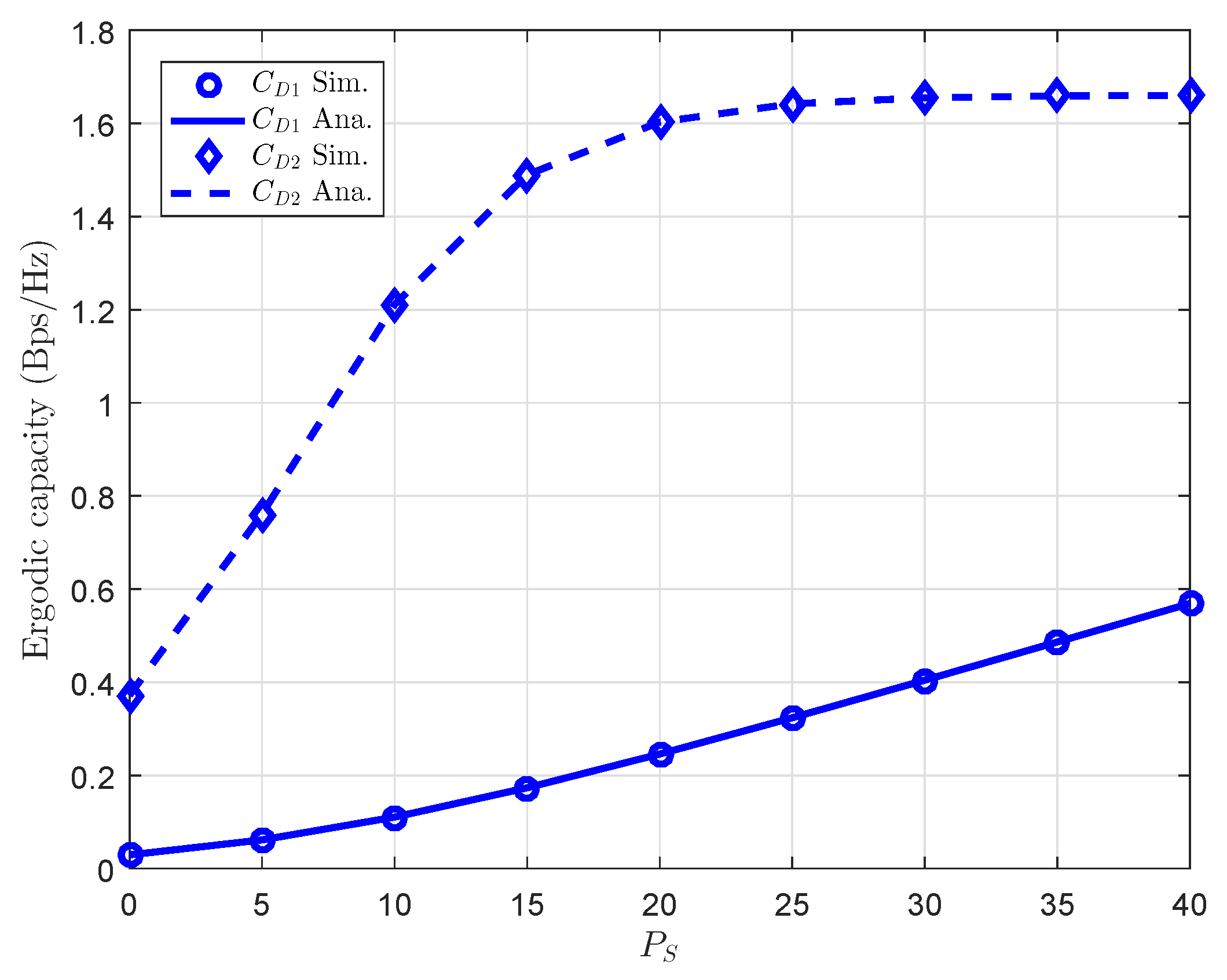
Finally, performance gap in ergodic capacity of both
D1 and
D2 can be seen clearly in
Figure 11. The main reason is that power allocation factor for each user is careful selected to guarantee quality of the proposed system.


