Modelling of a Hall Effect-Based Current Sensor with an Open Core Magnetic Concentrator

1
Faculty of Electrical Engineering, Tehcnical University of Sofia, 1000 Sofia, Bulgaria
2
Vocational School of Technical Sciences, Uludağ University, 16059 Nilufer/Bursa, Turkey
*
Author to whom correspondence should be addressed.
Sensors 2018, 18(4), 1260; https://doi.org/10.3390/s18041260
Submission received: 11 February 2018
/
Revised: 10 April 2018
/
Accepted: 16 April 2018
/
Published: 19 April 2018
(This article belongs to the Special Issue Small Devices and the High-Tech Society)
Abstract
:The present paper deals with the modelling of a Hall effect current sensor with open core magnetic concentrator. 3D magnetic field modelling is carried out using the finite element method (FEM) and Comsol Multiphysics software. Two rectangular core constructions are considered. Different geometric parameters of the magnetic concentrator are varied and their influence on the sensor characteristic is studied, with the aim of reducing the dependence on the output signal on the distance to the conductor. Of the studied parameters, core window length leads to the most significant change in the sensor characteristic. Future work can include the optimization of the sensor construction.
1. Introduction
Current sensors based on the Hall effect are widely used in different applications and are the subject of increasing interest in recent years [1,2,3,4]. The output signal of sensors without a magnetic core strongly depends on the distance between the conductor and the Hall sensor, and different approaches are used for eliminating this dependence [5,6,7]. Where possible, constructions with magnetic cores are used [8,9]. Commercially available current measuring apparatus based on Hall effect sensors usually include a closed magnetic core with a small gap where the Hall sensor is placed. In some specific cases, though, the employment of closed cores as magnetic concentrators is not possible due to the construction of the system where the current to be measured flows.
Different geometries of Hall sensors working in current mode are studied in [10]. To prove the accuracy of COMSOL models, they make comparison with results achieved from a model implemented in Verilog-A software. In [11], various schemes of magnetic biosensors that are used for the identification of a wide spectrum of biological, physical, and chemical agents are presented. By numerical simulations using the finite element method (FEM), bending-induced stress effects on ultrathin cross-shaped magnetic sensors are analyzed in [12]. One application of this type of sensors is electronic or tactile skin. In [13,14,15], different arrays of Hall sensors working in current mode are studied, and electronic interfaces that are used with sensors are presented. To improve the characteristics of the magnetic sensors in [16,17], optimal design solutions are studied and an optimal geometry of the Hall plate is proposed.
In fixed arrangements, the sensor could be easily calibrated for any type of magnetic concentrator and also for coreless design. In nonfixed arrangements, though, especially in the case when a closed core concentrator is not practically realizable, open core magnetic concentrators could be employed, thus reducing the error in the current measurement due to an error in the distance measurement.
In the present paper, 3D FEM modelling of the magnetic field in a Hall effect-based current sensor with an introduced magnetic concentrator of open core type is carried out with the aim of reducing the dependence of the output signal on the distance between the conductor and the Hall plate. This can give the opportunity of further design of a current sensor with preliminary estimated error due to the deviation of the conductor position.
2. Studied Constructions
Two constructions of the magnetic core of the current sensor are considered: a rectangular C-core with one air gap for the Hall sensor (referred to as construction with one air gap or concentrator with one air gap), and a rectangular magnetic core with two air gaps: one for the Hall sensor and one additional air gap, placed on the opposite leg (referred to as construction with two air gaps or concentrator with two air gaps).
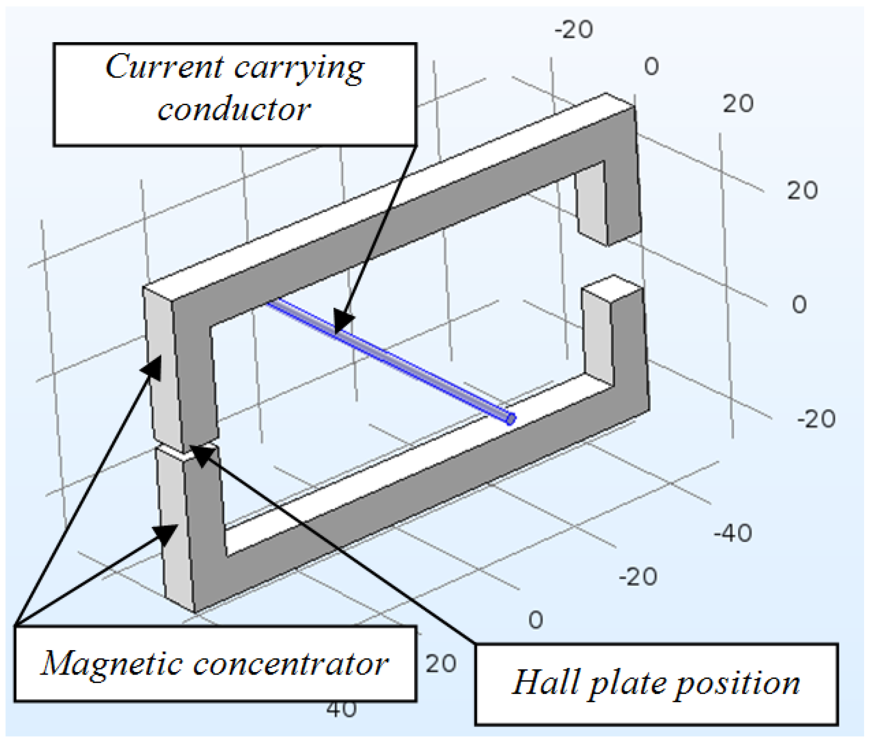
2.1. Construction with One Air Gap
The construction consists of two ferromagnetic legs, which on the one end are linked with a third leg with an air gap, where the Hall plate is placed (Figure 1). The dimensions given in the figure are in millimeters. The Hall plate is also included in the model (inside the air gap) and its dimensions are considered to be 0.24 × 0.24 × 0.1 mm.
2.2. Construction with Two Air Gaps
3. FEM Modelling
The finite element method is used for modelling the magnetic field of the two constructions. The Comsol Multiphysics program [18] has been employed for this purpose. The AC/DC module and Magnetic Fields and Electric Currents interfaces have been used. For computation of the Hall plate output voltage, the approach employed in [19] has been used.
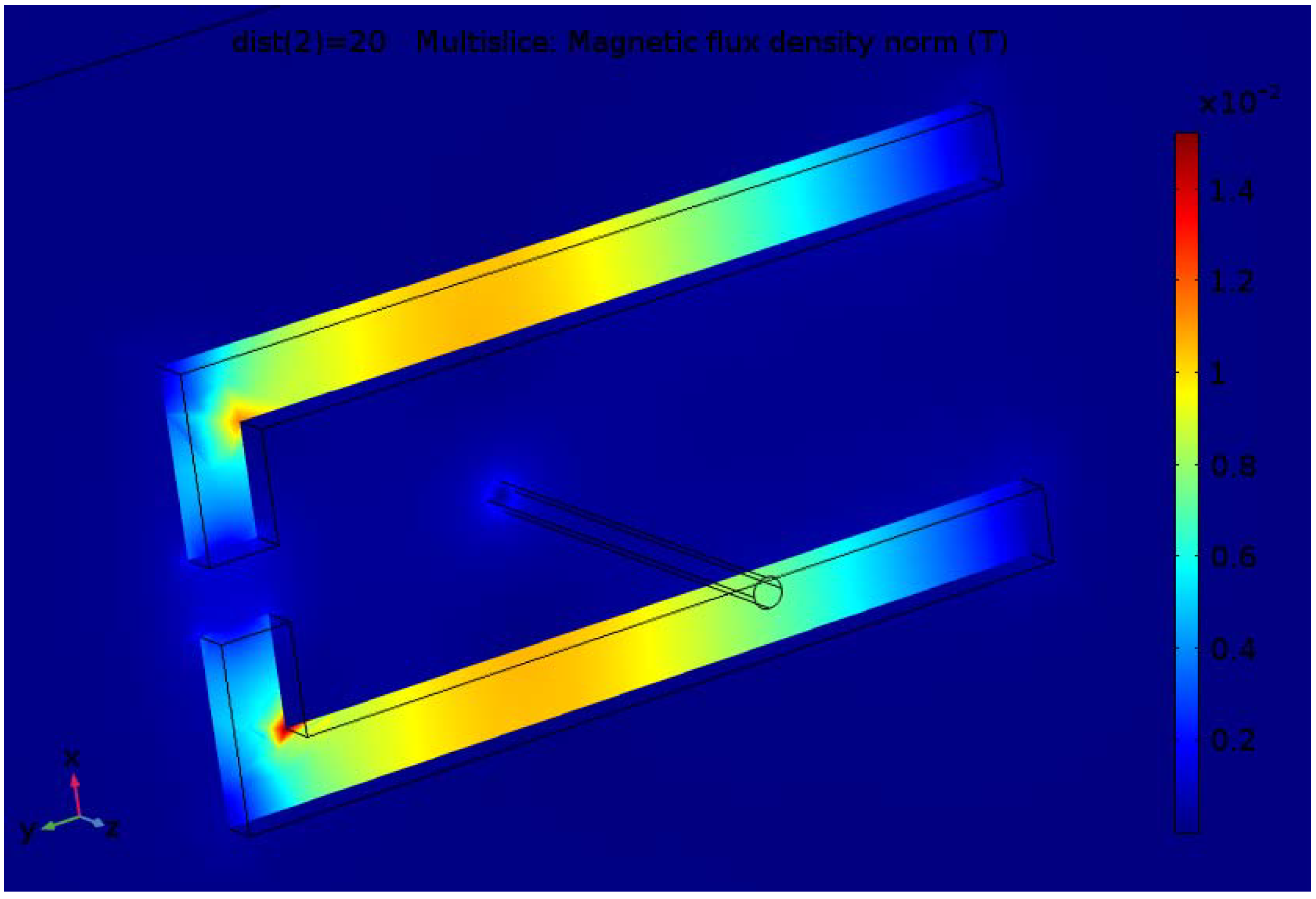
The finite element analysis is carried out for the 10 A value of the current in the conductor and different parameters of the magnetic concentrator. Results for the magnetic flux density distribution for one variant of the two considered constructions are shown in Figure 3 and Figure 4.
Although the inner dimensions of the concentrator with two gaps is greater than for the one with one gap, the flux density is greater due to introducing the leg with a second gap.
In order to estimate the effect of introducing the magnetic concentrator, the dependence of the magnetic flux density in the Hall plate (volume integral average) on the distance to the conductor for construction without a magnetic concentrator is shown in Figure 5a. In Figure 5b,c, the same dependence is shown for the constructions with concentrators with one and two gaps. Both relationships are close to a linear one, while for the coreless design (without concentrator) the dependence is strongly nonlinear.
Relative values of the flux density are used in order to allow comparison between the different curves.
4. Results for the Influence of Different Parameters
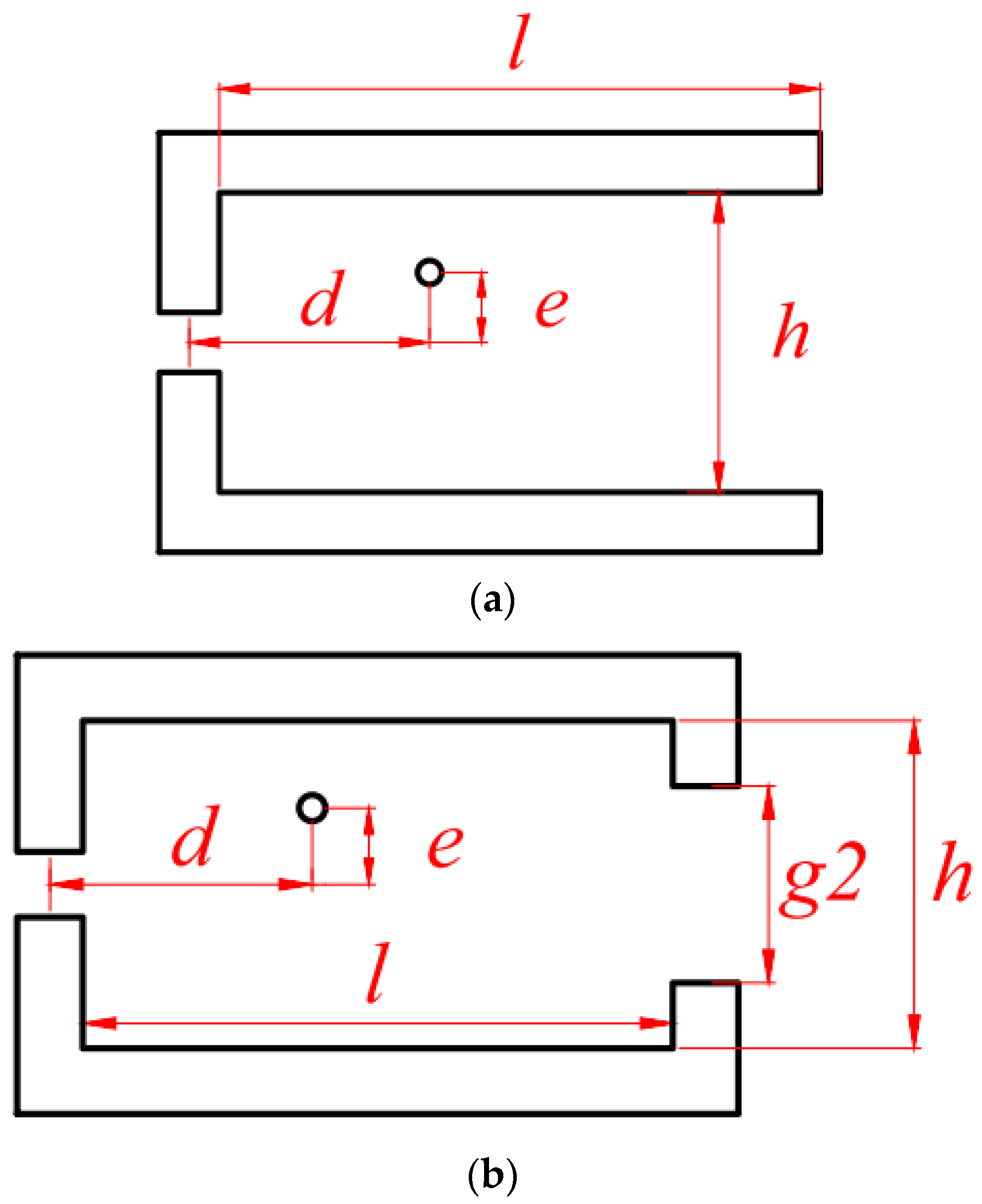
The influence of different geometric parameters has been studied for both constructions. The varied parameters are shown in Figure 6a,b. In addition to the distance between the Hall plate and the conductor (denoted by d), the parameters subject to variation are window length (l), window height (h), and eccentricity (e) of the conductor with respect to the central line. For the case of the concentrator with two gaps, the size gap2 of the additional air gap is also varied.
The other geometric parameters are fixed, as follows:
- -
- core cross section is of size 7 × 7 mm;
- -
- air gap accommodating the Hall plate is 1.5 mm;
- -
- conductor diameter is 2 mm.
4.1. Construction with One Air Gap
Three parameters have been varied for the construction with one air gap: the length l and height h of the window and deflection of the conductor from the central symmetry line e.
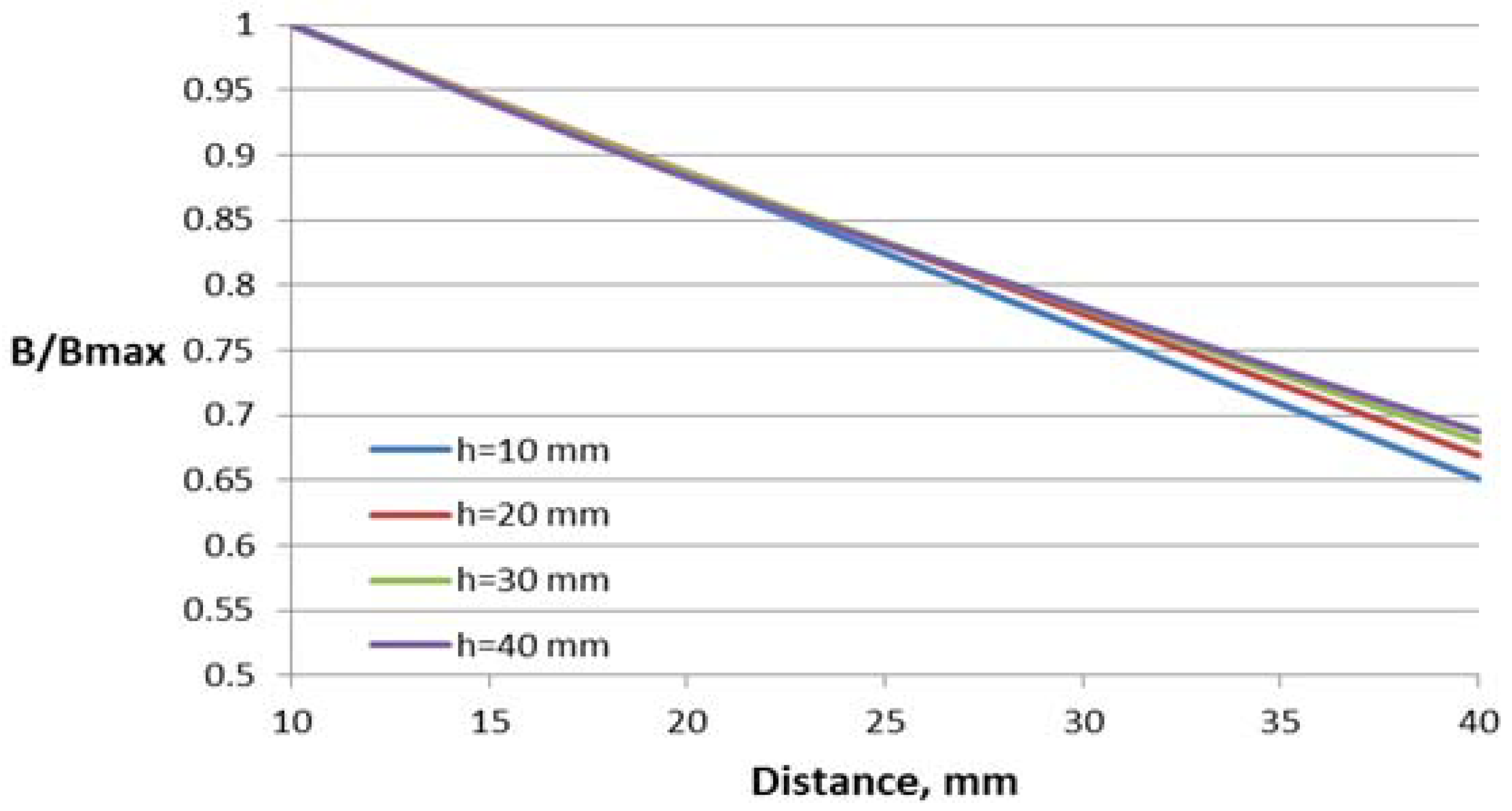
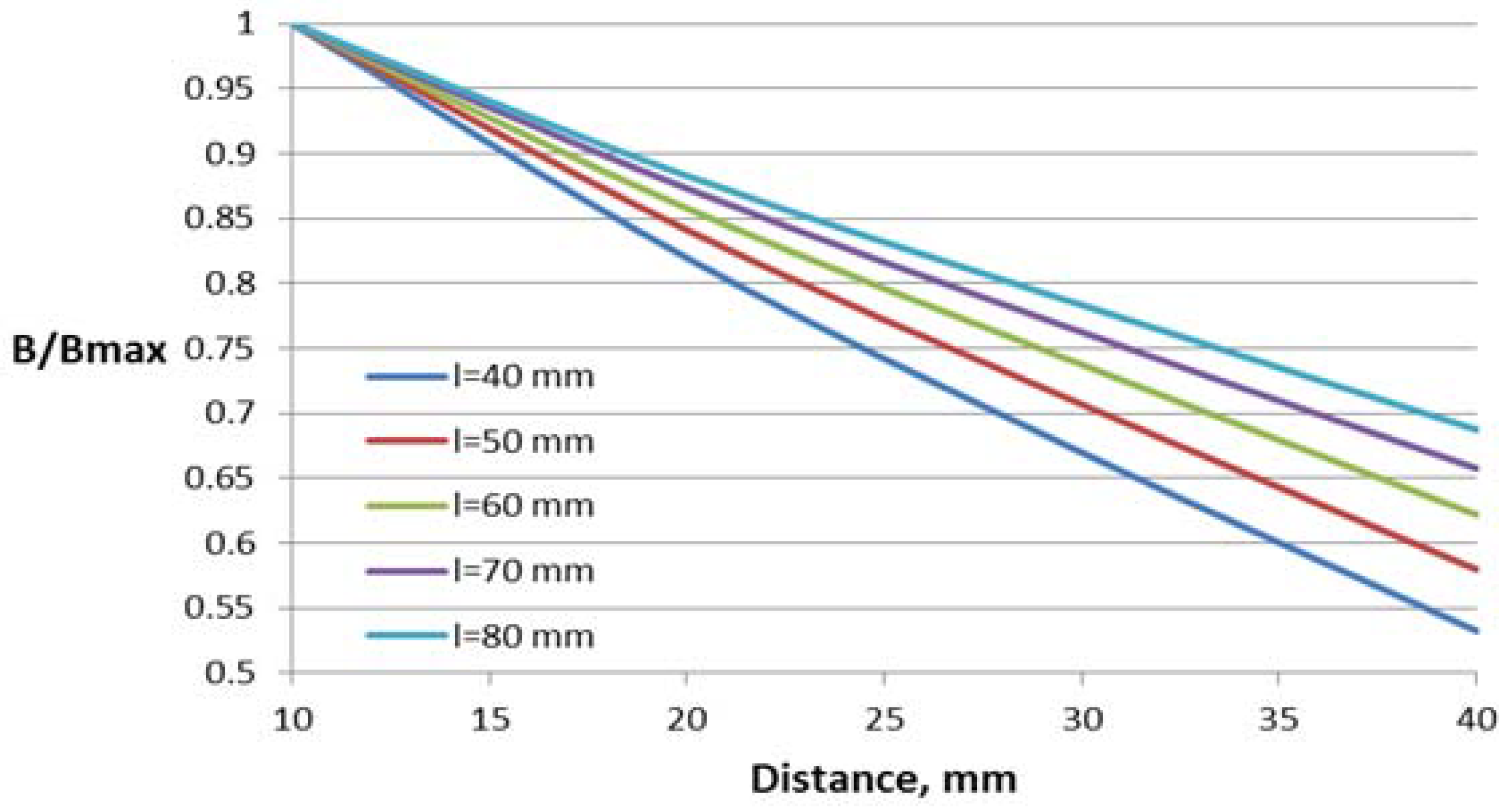
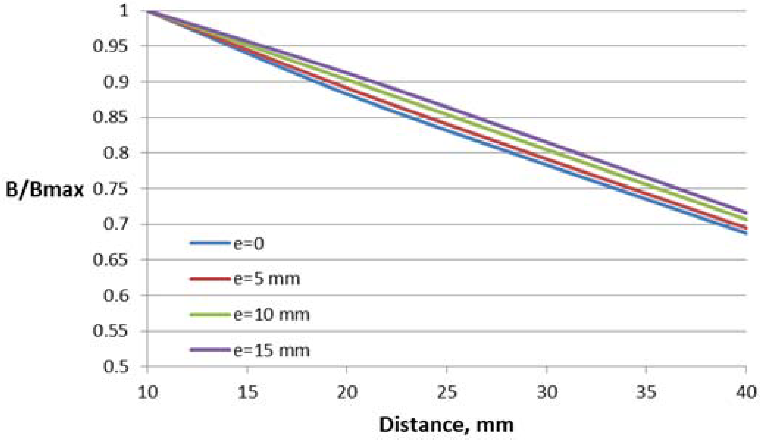
The dependence of the magnetic flux density B in the Hall plate (volume integral average) on the distance between the conductor and the Hall plate for different parameter values are shown in Figure 7, Figure 8 and Figure 9. For better comparison of the different characteristics, the flux density in the Hall plate is presented in relative units with respect to its maximal value Bmax, which is obtained in the plate at the minimal considered distance (10 mm) between the conductor and the Hall plate.
Core window length has a significant influence on the flux density–distance relationship, leading to about 30% difference between the flux density for the first and the last value of the length at the largest distance.
Variations of the core window height and deflection of the conductor from the central symmetry line do not lead to significant change in the characteristics (about 4–6% at the largest distance).
4.2. Construction with Two Air Gaps
Four parameters have been varied for the construction with two air gaps. In addition to the parameters varied for the case of one air gap, the value of the additional air gap is also varied.
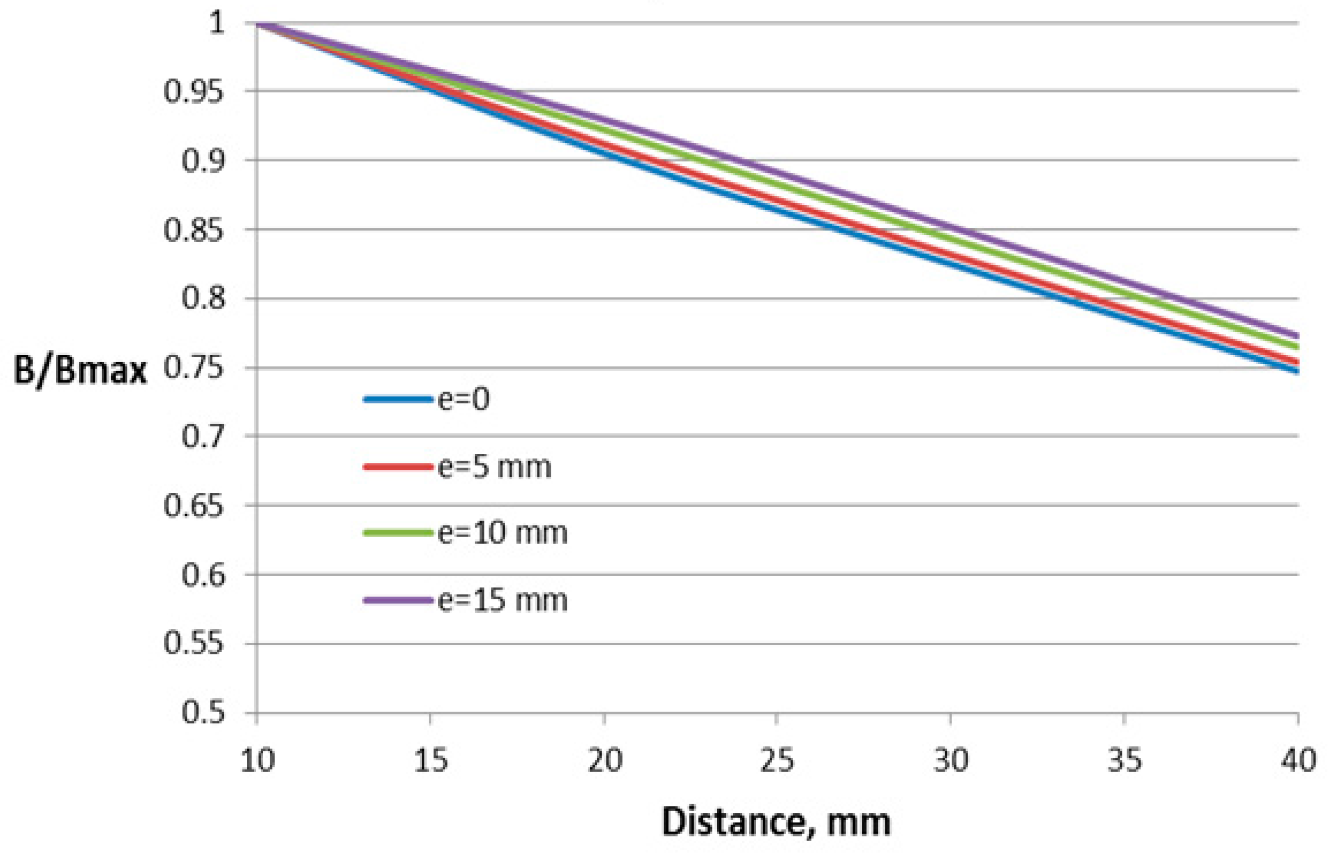
The dependences of the relative flux density on the distance between the conductor and Hall plate for different parameters of this construction are shown in Figure 10, Figure 11, Figure 12 and Figure 13.
For this construction, both sizes of the core window (length and height) influence the sensor performance. Regarding the influence of the second air gap, as it can be expected, the lowest dependence on the distance features the construction with the smallest value of the second air gap. For comparison, in Figure 13, the dependence of the construction with the closed core is also given.
For this construction, the window length and height have more influence on the dependence on the conductor position, leading to changes of 13% and 10%, respectively. The variation of the other two studied parameters results in less than 5% change in the characteristic.
All the obtained characteristics with open core magnetic concentrators, though, feature an almost linear dependence on the distance between the conductor and the Hall plate.
4.3. Results for Different Values of the Measured Current
For estimation of the influence of the value of the current on the output voltage signal from the Hall plate, the output signal has been computed for different values of the current, varying the latter from 10 to 40 A. The computations have been carried out using the approach in [19] for the construction with two air gaps and value of the second gap of 5 mm.
In Figure 14, the dependence of the Hall plate output voltage Vhall on the current I for different distances to the conductor is given. In Figure 15, the same family of curves has been presented as the dependence of the Hall plate output voltage on the distance to the conductor for different currents.
The obtained results give the possibility of estimating the maximal difference in the output signal when varying the distance from the conductor to the Hall plate from 10 to 40 mm. This maximal difference is less than 24% for all currents.
The linearity of the obtained dependencies could be used as an objective function in a future optimization. Having the best linear fit of the characteristics (Hall plate output voltage relative to the distance of the conductor to the Hall plate), it will be possible to design a current sensor with preliminary estimated current error with respect to the distance error.
5. Conclusions
Computer models for the constructions of Hall effect-based current sensors with additional open core magnetic concentrators are created. The employment of an open core magnetic concentrator leads to an almost linear dependence of the output signal on the distance between the conductor and the Hall plate. The influence of changing different geometric concentrator parameters is estimated for two constructions of the magnetic concentrator of rectangular shape, showing a more significant influence of the window length and height. The dependence of the Hall plate output voltage on the distance to the conductor has been obtained for different values of the current, and estimation of its linearity can be performed. This linearity can be the subject of further optimization with the aim of the design of a current sensor with an open core magnetic concentrator for nonfixed arrangements.
Acknowledgments
Financial support from Uludag University for covering costs of open access publishing is greatly acknowledged.
Author Contributions
I.Y., M.S. and I.B. performed the computer modelling, I.Y., M.S. and I.K. analyzed the results, I.Y. wrote the paper.
Conflicts of Interest
The authors declare no conflict of interest.
References
- Ramsden, E. Hall-Effect Sensors: Theory and Application, 2nd ed.; Newnes: Oxford, UK, 2011. [Google Scholar]
- Blagojević, M.; Jovanović, U.; Jovanović, I.; Mančić, D.; Popović, R. Realization and optimization of bus bar current transducers based on Hall effect sensors. Meas. Sci. Technol. 2016, 27, 1–11. [Google Scholar] [CrossRef]
- Wang, Z.; Shaygan, M.; Otto, M.; Schall, D.; Neumaier, D. Flexible Hall sensors based on graphene. Nanoscale 2016, 7683–7687. [Google Scholar] [CrossRef] [PubMed]
- Yang, D.; Ren, H.; Min, J.; Chen, H. A field-circuit collaborative simulation design method of Hall current sensor based on magnetic flux. In Proceedings of the 2015 International Conference on Electrical and Information Technologies for Rail Transportation; Lecture Notes in Electrical Engineering; Jia, L., Liu, Z., Qin, Y., Ding, R., Diao, L., Eds.; Springer: Berlin/Heidelberg, Germany, 2015; Volume 377, pp. 609–623. [Google Scholar]
- Chen, K.L.; Chen, N. A New Method for Power Current Measurement Using a Coreless Hall Effect Current Transformer. IEEE Trans. Inst. Meas. 2011, 60, 158–169. [Google Scholar] [CrossRef]
- Tsai, Y.P.; Chen, K.L.; Chen, Y.R.; Chen, N. Multifunctional Coreless Hall-Effect Current Transformer for the Protection and Mesaurement of Power Systems. IEEE Trans. Inst. Meas. 2014, 63, 557–565. [Google Scholar] [CrossRef]
- George, N.; Gopalakrishna, S. An improved anti-differential configuration based hall-effect current sensor. In Proceedings of the 2016 IEEE Annual India Conference (INDICON), Bangalore, India, 16–18 December 2016; pp. 1–5. [Google Scholar]
- Zhang, Q.; Liu, J.G.; Yang, Y. A new complementary symmetrical structure of using dual magnetic cores for open loop Hall-Effect current sensors. In Proceedings of the PCIM Europe 2015—International Exhibition and Conference for Power Electronics, Intelligent Motion, Renewable Energy and Energy Management, Nuremberg, Germany, 19–20 May 2015; pp. 1–8. [Google Scholar]
- Rushmer, R.; Annis, J.; Marasch, R.; Voborsky, G. Hall Effect Sensor Core with Multiple Air Gaps. U.S. Patent 9,285,437, 15 March 2016. [Google Scholar]
- Heidari, H.; Gatti, U.; Bonizzoni, E.; Maloberti, F. Low-Noise Low-Offset Current-Mode Hall Sensors. In Proceedings of the 2013 9th Conference on Ph.D. Research in Microelectronics and Electronics (PRIME), Villach, Austria, 24–27 June 2013; pp. 325–328. [Google Scholar]
- Nabaei, V.; Chandrawati, R.; Heidari, H. Magnetic biosensors: Modelling and simulation. Biosens. Bioelectron. 2018, 103, 69–86. [Google Scholar] [CrossRef] [PubMed]
- Heidari, H.; Wacker, N.; Roy, S.; Dahiya, R. Towards Bendable CMOS Magnetic Sensors. In Proceedings of the IEEE Conference on Ph.D. Research in Microelectronics and Electronics (PRIME), Glasgow, UK, 29 June–2 July 2015; pp. 314–317. [Google Scholar]
- Heidari, H.; Bonizzoni, E.; Gatti, U.; Maloberti, F. A current-mode CMOS integrated microsystem for current spinning magnetic hall sensors. In Proceedings of the 2014 IEEE International Symposium on Circuits and Systems (ISCAS), Melbourne, Australia, 1–5 June 2014; pp. 678–681. [Google Scholar]
- Heidari, H.; Bonizzoni, E.; Gatti, U.; Maloberti, F. Analysis and modeling of four-folded vertical Hall devices in current domain. In Proceedings of the 2014 10th Conference on Ph.D. Research in Microelectronics and Electronics, (PRIME 2014), Grenoble, France, 30 June–3 July 2014. [Google Scholar]
- Heidari, H.; Bonizzoni, E.; Gatti, U.; Maloberti, F. A 0.18-µm CMOS current-mode Hall magnetic sensor with very low bias current and high sensitive front-end. In Proceedings of the 2015 IEEE SENSORS, Valencia, Spain, 2–5 November 2014. [Google Scholar]
- Heidari, H.; Bonizzoni, E.; Gatti, U.; Maloberti, F.; Dahiya, R. Optimal geometry of CMOS voltage-mode and current-mode vertical magnetic hall sensors. In Proceedings of the 2015 IEEE SENSORS, Busan, Korea, 1–4 November 2015. [Google Scholar]
- Crescentini, M.; Biondi, M.; Romani, A.; Tartagni, M.; Sangiorgi, E. Optimum Design Rules for CMOS Hall Sensors. Sensors 2017, 17, 765. [Google Scholar] [CrossRef] [PubMed]
- Comsol Inc. COMSOL Multiphysics 5.2. User’s Guide; Comsol Inc.: Burlington, MA, USA, 2016. [Google Scholar]
- Sen, M.; Balabozov, I.; Yatchev, I.; Ivanov, R. Modelling of Current Sensor Based on Hall Effect. In Proceedings of the 15th International Conference on Electrical Machines, Drives and Power Systems (ELMA 2017), Sofia, Bulgaria, 1–3 June 2017. [Google Scholar]
Figure 1.
Construction with one air gap.

Figure 2.
Construction with two air gaps.

Figure 3.
Flux density distribution for the construction with one air gap.

Figure 4.
Flux density distribution for the construction with two air gaps.

Figure 5.
Dependence of the flux density on the distance to the conductor (a) no magnetic concentrator; (b) concentrator with one gap; (c) concentrator with two gaps.
Figure 5.
Dependence of the flux density on the distance to the conductor (a) no magnetic concentrator; (b) concentrator with one gap; (c) concentrator with two gaps.

Figure 6.
Parameters subject to variation for the two constructions: (a) construction with one air gap; (b) construction with two air gaps.
Figure 6.
Parameters subject to variation for the two constructions: (a) construction with one air gap; (b) construction with two air gaps.

Figure 7.
Dependence of the flux density on the distance to the conductor for the concentrator with one gap and different window lengths l.
Figure 7.
Dependence of the flux density on the distance to the conductor for the concentrator with one gap and different window lengths l.

Figure 8.
Dependence of the flux density on the distance to the conductor for the concentrator with one gap and different window heights h.
Figure 8.
Dependence of the flux density on the distance to the conductor for the concentrator with one gap and different window heights h.

Figure 9.
Dependence of the flux density on the distance to the conductor for the concentrator with one gap and different conductor deflections in the transversal direction e.
Figure 9.
Dependence of the flux density on the distance to the conductor for the concentrator with one gap and different conductor deflections in the transversal direction e.

Figure 10.
Dependence of the flux density on the distance to the conductor for the concentrator with two gaps and different window lengths l.
Figure 10.
Dependence of the flux density on the distance to the conductor for the concentrator with two gaps and different window lengths l.

Figure 11.
Dependence of the flux density on the distance to the conductor for the concentrator with two gaps and different window heights h.
Figure 11.
Dependence of the flux density on the distance to the conductor for the concentrator with two gaps and different window heights h.

Figure 12.
Dependence of the flux density on the distance to the conductor for the concentrator with two gaps and different conductor deflections in the transversal direction e.
Figure 12.
Dependence of the flux density on the distance to the conductor for the concentrator with two gaps and different conductor deflections in the transversal direction e.

Figure 13.
Dependence of the flux density on the distance to the conductor for the concentrator with two gaps and different values of the second air gap (gap2).
Figure 13.
Dependence of the flux density on the distance to the conductor for the concentrator with two gaps and different values of the second air gap (gap2).

Figure 14.
Dependence of the Hall plate voltage Vhall on the current for different distances to the conductor.
Figure 14.
Dependence of the Hall plate voltage Vhall on the current for different distances to the conductor.

Figure 15.
Dependence of the Hall plate voltage Vhall on the distance to the conductor for four different currents.
Figure 15.
Dependence of the Hall plate voltage Vhall on the distance to the conductor for four different currents.

© 2018 by the authors. Licensee MDPI, Basel, Switzerland. This article is an open access article distributed under the terms and conditions of the Creative Commons Attribution (CC BY) license (http://creativecommons.org/licenses/by/4.0/).
Share and Cite
MDPI and ACS Style
Yatchev, I.; Sen, M.; Balabozov, I.; Kostov, I. Modelling of a Hall Effect-Based Current Sensor with an Open Core Magnetic Concentrator. Sensors 2018, 18, 1260. https://doi.org/10.3390/s18041260
AMA Style
Yatchev I, Sen M, Balabozov I, Kostov I. Modelling of a Hall Effect-Based Current Sensor with an Open Core Magnetic Concentrator. Sensors. 2018; 18(4):1260. https://doi.org/10.3390/s18041260
Chicago/Turabian StyleYatchev, Ivan, Mehmet Sen, Iosko Balabozov, and Ivan Kostov. 2018. "Modelling of a Hall Effect-Based Current Sensor with an Open Core Magnetic Concentrator" Sensors 18, no. 4: 1260. https://doi.org/10.3390/s18041260
Note that from the first issue of 2016, this journal uses article numbers instead of page numbers. See further details here.