Intensity Demodulated Refractive Index Sensor Based on Front-Tapered Single-Mode-Multimode-Single-Mode Fiber Structure


Abstract
:1. Introduction
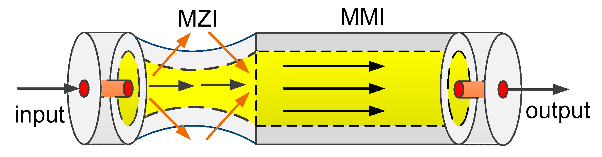
2. Principles
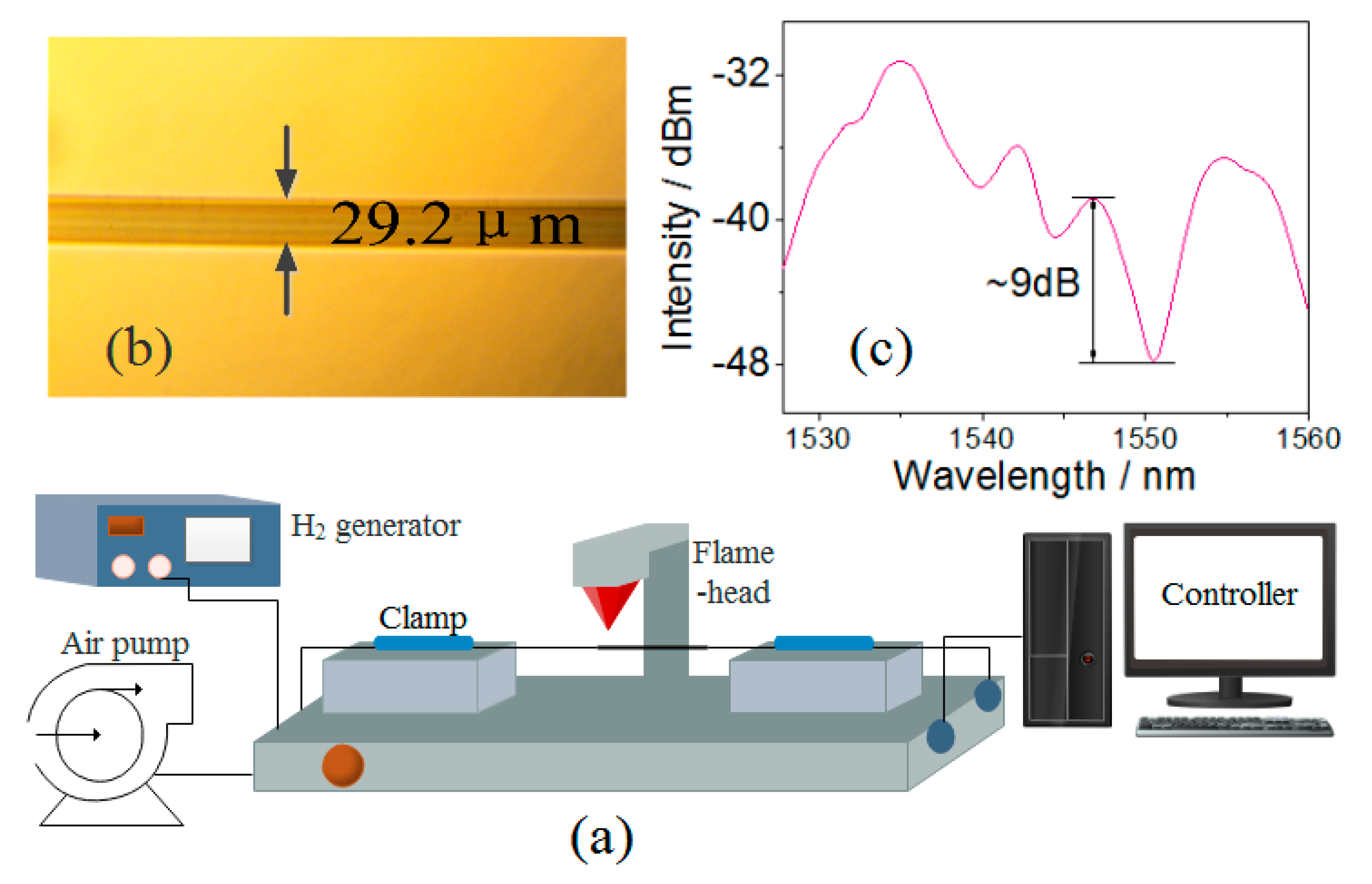
3. Fabrication
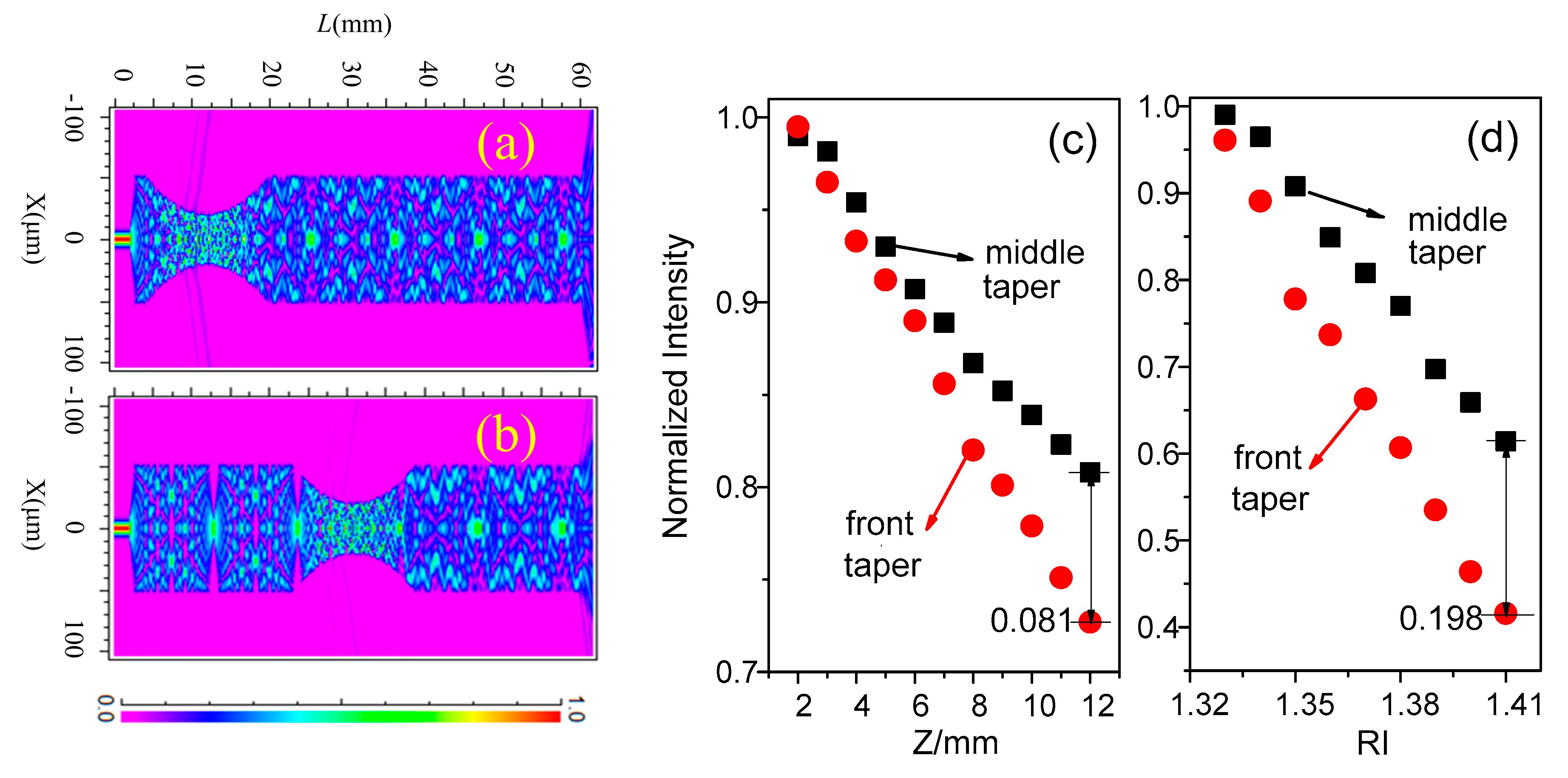
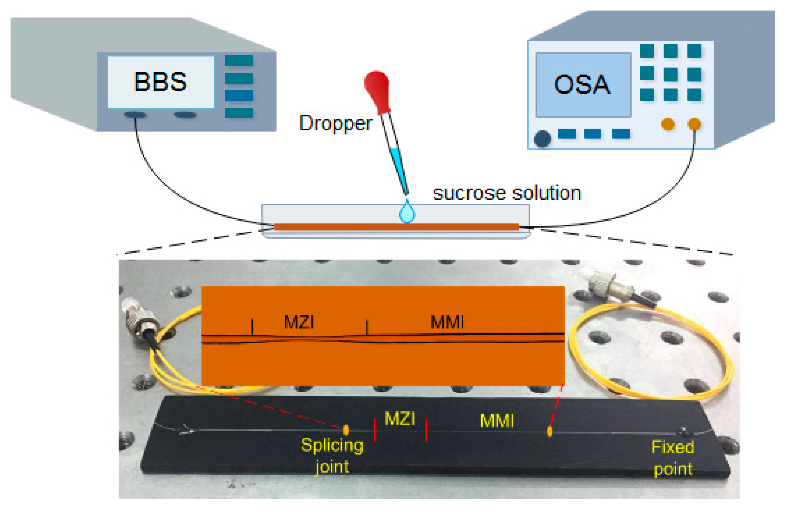
4. Experiments and Results
5. Conclusions
Author Contributions
Funding
Conflicts of Interest
References
- Ramakrishnan, M.; Rajan, G.; Semenova, Y.; Farrell, G. Overview of Fiber optic sensor technologies for strain/temperature sensing applications in composite materials. Sensors 2016, 16, 99. [Google Scholar] [CrossRef] [PubMed]
- Frazão, O.; Martynkien, T.; Baptista, J.M.; Santos, J.L.; Urbancayk, W.; Wojcik, J. Optical refractometer based on a birefringent Bragg grating written in an H-shaped fiber. Opt. Lett. 2009, 34, 76–78. [Google Scholar] [CrossRef] [PubMed]
- Geng, T.; Zhang, S.; Peng, F.; Yang, W.L.; Sun, C.T.; Chen, X.D.; Zhou, Y.; Hu, Q.H.; Yuan, L.B. A temperature-insensitive refractive index sensor based on no-core fiber embedded long period grating. J. Lightwave Technol. 2017, 35, 5391–5396. [Google Scholar] [CrossRef]
- Dash, J.N.; Jha, R. Graphene-based birefringent photonic crystal fiber sensor using surface plasmon resonance. IEEE Photonics Technol. Lett. 2014, 26, 1092–1095. [Google Scholar] [CrossRef]
- Hasan, M.R.; Akter, S.; Rifat, A.A.; Rana, S.; Ahmed, K.; Ahmed, R.; Subbaraman, H.; Abbott, D. Spiral photonic crystal fiber-based dual-polarized surface plasmon resonance biosensor. IEEE Sens. J. 2018, 18, 133–140. [Google Scholar] [CrossRef]
- Chen, Y.F.; Wang, Y.; Chen, R.Y.; Yang, W.K.; Liu, H.; Liu, T.G.; Han, Q. A hybrid multimode interference structure-based refractive index and temperature fiber sensor. IEEE Sens. J. 2016, 16, 331–335. [Google Scholar] [CrossRef]
- Lin, H.Y.; Huang, C.H.; Cheng, G.L.; Chen, N.K.; Chui, H.C. Tapered optical fiber sensor based on localized surface plasmon resonance. Opt. Express 2012, 20, 21693–21701. [Google Scholar] [CrossRef] [PubMed]
- Rifat, A.A.; Mahdiraji, G.A.; Yong, M.S.; Ahmed, R.; Shee, Y.G.; Mahamd Adikam, F.R. Highly sensitive multi-core flat fiber surface plasmon resonance refractive index sensor. Opt. Express 2016, 24, 2485–2495. [Google Scholar] [CrossRef] [PubMed]
- Wang, P.F.; Farrell, G.; Brambilla, G.; Ding, M.; Semenova, Y.; Wu, Q. Investigation of single-mode-multimode–single-mode and single-mode–tapered-multimode–single-mode fiber structures and their application for refractive index sensing. J. Opt. Soc. Am. B 2011, 28, 1180–1186. [Google Scholar] [CrossRef]
- Silva, S.; Pachon, E.G.P.; Franco, M.A.R.; Hayashi, J.G.; Malcata, F.X.; Frazao, O.; Jorge, P.; Cordeiro, C.M.B. Ultrahigh-sensitivity temperature fiber sensor based on multimode interference. Appl. Opt. 2012, 51, 3236–3242. [Google Scholar] [CrossRef] [PubMed]
- Kumar, M.; Kumar, A.; Tripathi, S.M. A comparison of temperature sensing characteristics of SMS structures using step and graded index multimode fibers. Opt. Commun. 2014, 32, 222–226. [Google Scholar] [CrossRef]
- Shao, M.; Qiao, X.G.; Fu, H.W.; Li, H.D.; Jia, Z.N.; Zhou, H. Refractive index sensing of SMS fiber structure based Mach-Zehnder interferometer. IEEE Photonics Technol. Lett. 2014, 26, 437–439. [Google Scholar] [CrossRef]
- Wang, P.F.; Brambilla, G.; Ding, M.; Semenova, Y.; Wu, Q.; Farrell, G. High-sensitivity, evanescent field refractometric sensor based on a tapered, multimode fiber interference. Opt. Lett. 2011, 36, 2233–2235. [Google Scholar] [CrossRef] [PubMed]
- Yang, Z.H.; Sun, H.; Gang, T.T.; Liu, N.; Li, J.C.; Meng, F.; Qiao, X.G.; Hu, M.L. Refractive index and temperature sensing characteristics of an optical fiber sensor based on a tapered single mode fiber/polarization maintaining fiber. Chin. Opt. Lett. 2016, 14, 14–18. [Google Scholar]
- Wang, P.F.; Zhao, H.Y.; Wang, X.F.; Farrell, G.; Brambilla, G. A review of multimode interference in tapered optical fibers and related applications. Sensors 2018, 18, 858. [Google Scholar] [CrossRef] [PubMed]
- Zhang, C.B.; Ning, T.G.; Li, J.; Pei, L.; Li, C.; Lin, H. Refractive index sensor based on tapered multicore fiber. Opt. Fiber Technol. 2017, 33, 71–76. [Google Scholar] [CrossRef]
- Zhao, Y.; Cai, L.; Hu, H.F. Fiber-optic refractive index sensor based on multi-tapered SMS fiber structure. IEEE Sens. J. 2015, 15, 6348–6353. [Google Scholar] [CrossRef]
- Fu, H.W.; Jiang, Y.H.; Ding, J.J.; Zhang, J.L. Low temperature cross-sensitivity humidity sensor based on a U-shaped microfiber interferometer. IEEE Sens. J. 2017, 17, 644–649. [Google Scholar] [CrossRef]
- Zhang, M.; Fu, H.W.; Ding, J.J.; Li, H.D.; Zhang, J.L.; Zhu, Y.; Shao, M. High sensitivity interferometric microfiber ammonia sensor based on optical fiber taper. Acta Photonica Sin. 2017, 47, 170–175. [Google Scholar] [CrossRef]
- Zhang, Y.; Zou, W.W.; Li, X.W.; Mao, J.W.; Jiang, W.N.; Chen, J.P. Modal interferometer based on tapering single-mode-multimode-single-mode fiber structure by hydrogen flame. Chin. Opt. Lett. 2012, 10, 34–36. [Google Scholar]
- Yang, B.Y.; Niu, Y.X.; Yang, B.W.; Hu, Y.H.; Dai, L.L.; Yin, Y.H.; Ding, M. High sensitivity curvature sensor with intensity demodulation based on single-mode-tapered multimode-single-mode fiber. IEEE Sens. J. 2018, 18, 1094–1099. [Google Scholar]
- Yadav, T.K.; Narayanaswamy, R.; Abu Bakar, M.H.; Kamil, Y.M.; Mahdi, M.A. Single mode tapered fiber-optic interferometer based refractive index sensor and its application to protein sensing. Opt. Express 2014, 22, 22802–22807. [Google Scholar] [CrossRef] [PubMed]
- Li, E.; Wang, X.L.; Zhang, C. Fiber-optic temperature sensor based on interference of selective higher-order modes. Appl. Phys. Lett. 2006, 89, 369–449. [Google Scholar] [CrossRef]
- Yoon, M.S.; Park, S.; Han, Y.G. Simultaneous measurement of strain and temperature by using a micro-tapered fiber grating. J. Lightwave Technol. 2012, 30, 1156–1160. [Google Scholar] [CrossRef]
- Zhang, X.D.; Li, T.Y.; Yang, J.R. Stabilize and flatten multi-wavelength erbium-doped fiber laser through accurate hybrid dual-ring-configuration control. Appl. Sci. 2017, 7, 1290. [Google Scholar] [CrossRef]
- Rifat, A.A.; Mahdiraji, G.A.; Sua, Y.M.; Shee, Y.G.; Ahmed, R.; Chow, D.M.; Mahamd Adikan, F.R. Surface plasmon resonance photonic crystal fiber biosensor: A practical sensing approach. IEEE Photonics Technol. Lett. 2015, 27, 1628–1631. [Google Scholar] [CrossRef]
- Liu, D.J.; Mallik, A.K.; Yuan, J.H.; Yu, C.X.; Farrell, G. High sensitivity refractive index sensor based on a tapered small core single-mode fiber structure. Opt. Lett. 2015, 40, 4166–4169. [Google Scholar] [CrossRef] [PubMed] [Green Version]
- Ding, Z.W.; Lang, T.T.; Wang, Y.; Zhao, C.L. Surface plasmon resonance refractive index sensor based on tapered coreless optical fiber structure. J. Lightwave Technol. 2017, 35, 4734–4739. [Google Scholar] [CrossRef]


| Structures | Detection RI Range | Sensitivity (nm/RIU) | Sensitivity (dB/RIU) | Resolution (RIU) | Refs. |
|---|---|---|---|---|---|
| tapered fiber with localized SPR | 1.333–1.403 | 51 | — | 3.2 × 10⁻⁵ | [7] |
| SMS by chemical etching | 1.33–1.432 | — | 182.48 | 5.48 × 10⁻⁵ | [9] |
| SMS cascaded TCF | 1.333–1.403 | 148.27 | 112.37 | 1.34 × 10⁻⁴ | [12] |
| middle-tapered SMS | 1.33–1.44 | 487 | — | 2.05 × 10⁻⁵ | [13] |
| ~1.44 | 1913 | 5.23 × 10⁻⁶ | |||
| tapered multi-core fiber | 1.345–1.377 | 171.2 | 63.59 | 2.92 × 10⁻⁴ | [16] |
| multi-tapered SMS | 1.333–1.375 | 261.9 | 170.2 | — | [17] |
| tapered small-core fiber | 1.34–1.346 | 1198.3 | — | 0.83 × 10⁻⁵ | [27] |
| 1.375–1.384 | 2123.6 | — | 4.7 × 10⁻⁶ | ||
| 1.43–1.432 | 19212.5 | — | 5.2 × 10⁻⁷ | ||
| tapered fiber with SPR | 1.33–1.391 | 2238.4 | — | — | [28] |
| 1.386–1.416 | 866.1 | — | — | ||
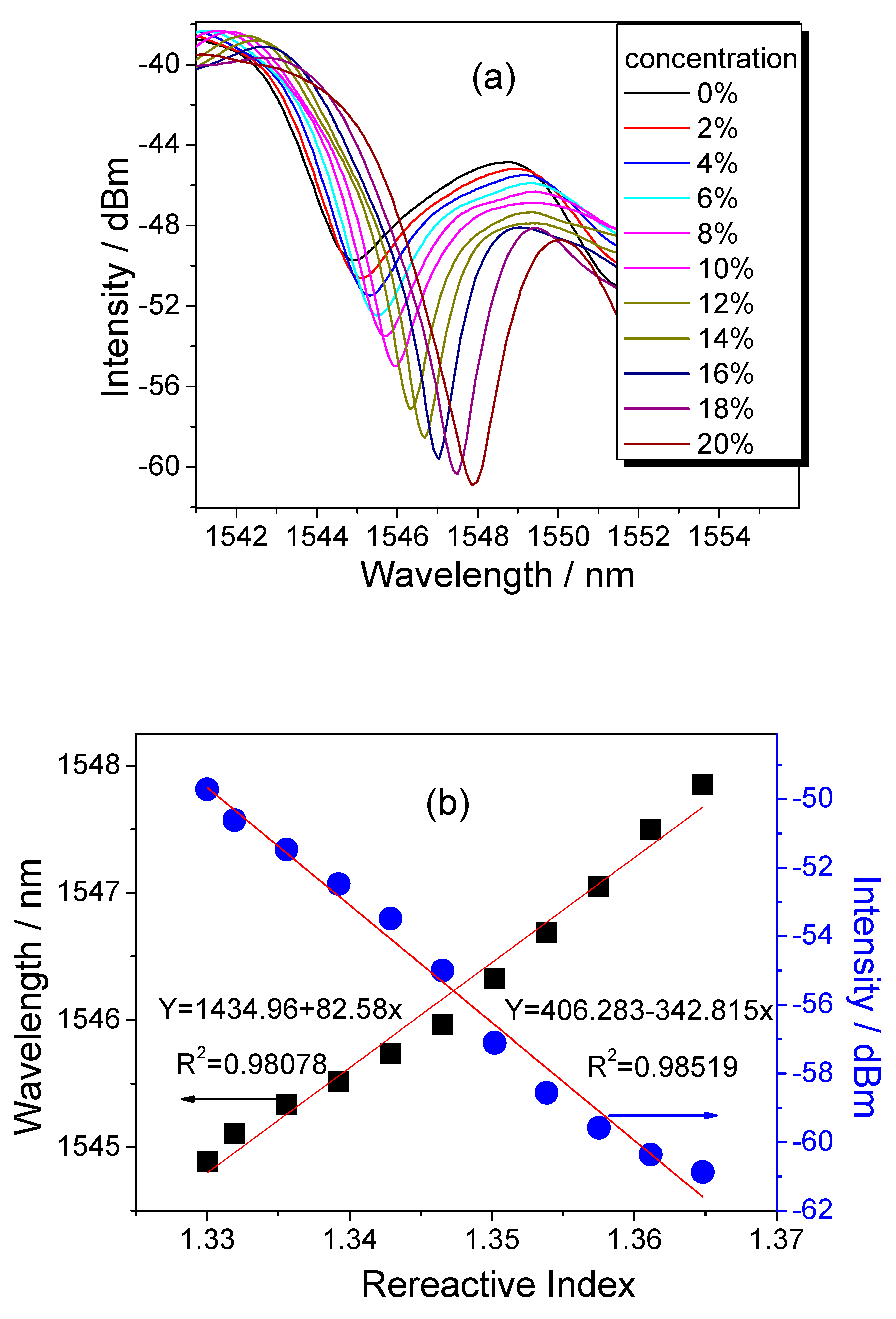
| front taper-SMS | 1.33–1.37 | 82.58 | −342.8 | 2.92 × 10⁻⁵ | Our work |
© 2018 by the authors. Licensee MDPI, Basel, Switzerland. This article is an open access article distributed under the terms and conditions of the Creative Commons Attribution (CC BY) license (http://creativecommons.org/licenses/by/4.0/).
Share and Cite
Kang, J.; Yang, J.; Zhang, X.; Liu, C.; Wang, L. Intensity Demodulated Refractive Index Sensor Based on Front-Tapered Single-Mode-Multimode-Single-Mode Fiber Structure. Sensors 2018, 18, 2396. https://doi.org/10.3390/s18072396
Kang J, Yang J, Zhang X, Liu C, Wang L. Intensity Demodulated Refractive Index Sensor Based on Front-Tapered Single-Mode-Multimode-Single-Mode Fiber Structure. Sensors. 2018; 18(7):2396. https://doi.org/10.3390/s18072396
Chicago/Turabian StyleKang, Jing, Jiuru Yang, Xudong Zhang, Chunyu Liu, and Lu Wang. 2018. "Intensity Demodulated Refractive Index Sensor Based on Front-Tapered Single-Mode-Multimode-Single-Mode Fiber Structure" Sensors 18, no. 7: 2396. https://doi.org/10.3390/s18072396