A Metamaterial-Based Compact Planar Monopole Antenna for Wi-Fi and UWB Applications


School of Computer Science and Engineering, Central South University, Changsha 410083, China
*
Author to whom correspondence should be addressed.
Sensors 2019, 19(24), 5426; https://doi.org/10.3390/s19245426
Submission received: 16 November 2019
/
Revised: 6 December 2019
/
Accepted: 7 December 2019
/
Published: 9 December 2019
(This article belongs to the Special Issue Antenna Technologies for Microwave Sensors)
Abstract
:Ultrawideband (UWB) antennas are widely used as core devices in high-speed wireless communication. A novel compact UWB monopole antenna with an additional narrow band for Wi-Fi applications comprising a metamaterial (MTM) is proposed in this paper. The antenna has a compact size of 27 × 33 mm2 and consists of a V-shaped slot with two rectangular slots in the radiation patch. The inductance and capacitance develop due to the V-shaped slot in the radiation patch. The proposed antenna has −10 dB bandwidths of 3.2 GHz to 14 GHz for UWB and 2.38 GHz to 2.57 GHz for narrowband, corresponding to 144% and 7.66% fractional bandwidths, respectively. The measured gain and efficiency meet the desired values for UWB and Wi-Fi applications. To verify the performance of the antenna, the proposed antenna is fabricated and tested. The simulated and measured results agree well at UWB frequencies and Wi-Fi frequencies, and the antenna can be used as a smart device for portable IoT applications.
1. Introduction
Ultrawideband technology has promising prospects in short-range communication systems due to its attractive characteristics such as broad bandwidth, high data-rates, low power spectrum levels, and good radiation performance [1,2]. The UWB frequency range is defined as 3.1–10.6 GHz by the Federal Communications Commission (FCC) [3,4]. UWB antennas play a role in many applications, such as surveillance systems, medical applications, wireless sensor networks, and the Internet of Things (IoT) [5,6,7,8]. However, there are limitations on UWB antennas. These antennas are still large in size, and some frequency bands for short-range communications are not in the UWB spectrum. It would be advantageous to extend the scope of short-range communication systems and to meet commercial and functional requirements, which would require the addition of more frequency bands and a more compact size of UWB antennas for various services.
A number of approaches have been described in the literature for achieving UWB characteristics. In [9,10,11,12,13,14], the UWB technique was realized through split-ring resonators. Split-ring resonators can be used in many ways, such as for the etching of the patch or ground plane, embedded inside or onto the antenna substrate with different structures, and with a capacitive-loaded strip (CLS). Moreover, the analysis of these structures was always based on several factors, such as wider bandwidth, size, composition, and density. In [15,16,17,18,19], the UWB technique was implemented with a defective ground plane and different shapes of slots or stubs. Although some of these antennas were miniaturized in size, they did not integrate the UWB spectrum with other useful frequency bands for short-range communications.
The concept of UWB technology combined with other short-range communication technologies is a stimulating research topic for enhancing the functionality of radio services. For example, the integration of Wi-Fi with UWB technology can combine Wi-Fi-based localization with UWB-based localization to obtain a hybrid approach that provides sufficient accuracy without the cost of deploying an entire UWB infrastructure [20]. Moreover, in body area network (BAN) communications for gateway services, we can integrate UWB technology with the application of Wi-Fi sensors for effective data transmission in medical applications [21]. In the literature, various methods were reported to achieve UWB bands with other bands, such as using a rectangular-shaped monopole strip [22,23], an elliptical-shaped stub at the high-concentrated current area in the ground plane [24], the strong coupling of complementary sprit-ring resonator (CSRR) or miniaturized resonant capacitors [25,26], and an L-shaped slot and a meander line [27,28,29], for achieving narrowband features in UWB antennas. However, most of these antennas are bulky in size, which is a challenge for the miniaturization of the antenna size. Moreover, in [25], the UWB spectrum was not achieved together with narrow-band. In [26], an antenna was presented with a complex structure to achieve Wi-Fi and UWB bands. Likewise, in [28], an antenna was presented with a bandwidth from 4.5 GHz to 11 GHz which was an incomplete operational range for UWB application. Despite these many designs, we still need low-profile and compact UWB antennas for integration with other frequency bands using simple etching techniques.
In this paper, we proposed a compact monopole antenna for Wi-Fi and UWB applications. The main goal was to maintain the design specifications and antenna coverage for wideband operations as well as to increase the operating bandwidth. This antenna operates well between 2.38–2.57 GHz for narrowband and 3.2–14 GHz for ultrawideband. First, a canonical UWB antenna was designed, and then, by loading a V-shaped resonator, we integrated the narrowband with the UWB in an innovative way. The proposed antenna design, characteristics, and experimental results are discussed in the following sections.
2. Antenna Design and Methodology
2.1. Antenna Geometry
The presented antenna, as shown in Figure 1, exhibits dual-band operations with the help of antenna-loaded elements. The monopole antenna contains a 14.64 × 17 mm2 radiation patch. The microstrip feedline length is set to 13.5 mm with a width of 2.3 mm to achieve 50 Ω characteristic impedance. The proposed antenna is designed on an FR-4 substrate with a dielectric constant of 4.4, and the tangent loss is δ = 0.02. In Figure 2, the V-slot is defined with an angle of α along with rectangular slots, and the realization of the optimum parameters is discussed in the parametric study. The obtained values of the optimized patch are given in Table 1. There is a protracted area in the patch structure with the feedline, which helps to control the surface current. A stepped structure in the ground plane is used to extend the impedance bandwidth.
2.2. Composite Right Left Hand (CRLH) Metamaterial (MTM) Theory
To design a dual-band antenna for the Wi-Fi band and ultrawideband, we introduce inductive and capacitive elements by etching the radiation patch. These reactive elements introduce a phase element between the voltage and current, such as gap capacitance [25] and meander line inductance [29]. To obtain CRLH transmission, we etch the radiation patch, which produces capacitive effects. These effects cause backward waves that travel along the radiation patch to obtain the desired frequency resonant bands and improve the radiation performance along the direction of the radiation patch. The length and width of the slots play a vital role in controlling the magnitudes of the capacitance and inductance. To obtain the properties of the negative refractive index, left-hand effects are observed for a specific range of frequencies. In this novel structure, we observe the strong control of the resonance frequency of the Wi-Fi band and X-band due to CRLH. The CRLH behavior always works as an LC resonator or LC component [30,31]. The inductance and capacitance for series branch resonators and shunt branch resonators are given as follows:
where the subscripts L and R denote left-handed (LH) and right-handed (RH) possessions, respectively. The resonant frequency of the CRLH components for the LC circuit is determined by
where is the left-hand resonant frequency, and is the right-hand resonant frequency.
To determine the dispersion relation of a CRLH transmission, we can use the following relationships:
where is the phase function of frequency, which can be purely real or purely imaginary depending on whether the radicand is positive or negative; and denote series and shunt-branch resonators, respectively.
The CRLH is increasingly dispersive as the frequency increases because the phase velocity (vp = ω/β) becomes increasingly dependent on the resonance frequency, which also shows that low frequencies dominate the LH while high frequencies dominate the RH. From Equation (3), we can identify whether the proposed model follows CRLH properties. In general, the series and shunt resonances of CRLH are different due to unbalanced cases because left-handed transmission supports electromagnetic waves with phase and group velocities that are antiparallel to each other. The apparent backward wave propagation is a key characteristic of CRLH transmission. Due to backward propagation, there is a certain shift in the transition frequency, called the CRLH gap. This gap is due to the left-handed effects. In the designed structure, the V-shaped resonator acts as a shunt capacitor and controls the voltage of the radiation patch to increase the power of the transmission line and reduce the antenna loss. If the bandgap for the left and right-hand region vanishes, then the CRLH region is in a balanced state. In a balanced state, the system impedance Zo, left-hand impedance ZL, and right-hand impedance ZR are equal. Using Equation (6), we can determine the left-hand and right-hand impedances. The characteristic impedance Zc is always frequency-dependent, as given in Equation (7), and can be related to the material intrinsic impedance .
The characteristic impedance for balanced and unbalanced CRLH transmission is illustrated in Figure 3. In this figure, ωo is a transition frequency, as illustrated in Equation (8), where ωCL is the lower cut off frequency and ωCR is the higher cut off frequency. The transition frequency separates the left-handed region from the right-handed region. In determining the CRLH region, the permittivity ε and permeability µ values indicate a negative index for transition frequencies, as given in Equations (9) and (10). If the index is positive, then the material is referred to as right-handed, and if the index is negative, then the material is referred to as left-handed.
2.3. Antenna Parametric Study
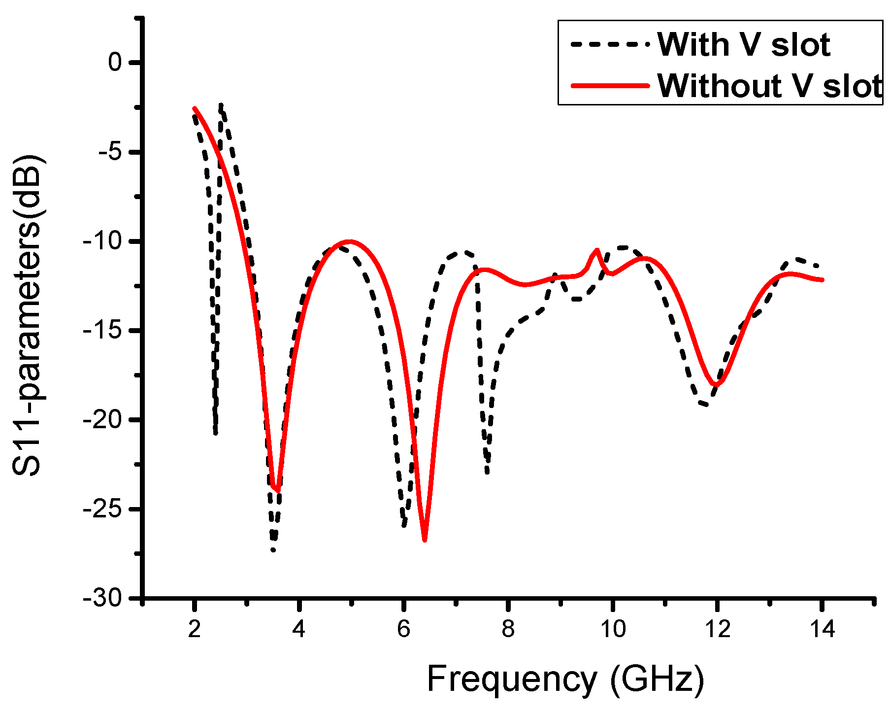
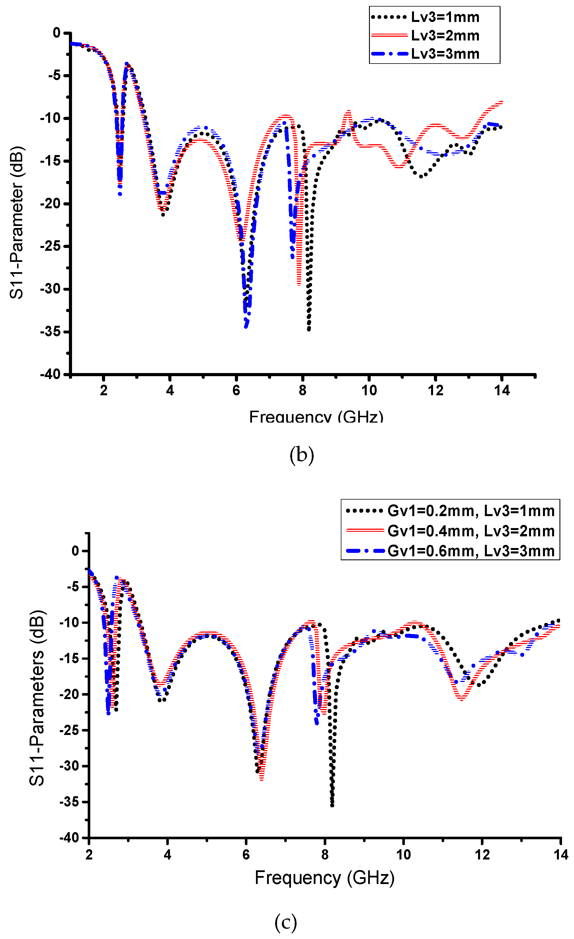
In this novel structure, we introduce a V-shaped resonator that gives us a narrow band for the desired Wi-Fi band, as shown in Figure 4. Furthermore, the V-shaped slot with extended slots shows us the CRLH characteristics, and by varying Gv1, we can adjust our narrow-band resonance frequency from 2.29 GHz to 2.75 GHz, as shown in Figure 5a. We observe that this parameter has a significant effect on the resonance frequency of the narrowband and has a small effect on the UWB spectrum. Likewise, by varying Lv3, we observe the same frequency resonance change at the satellite band from 7.5 to 8.3 GHz, as shown in Figure 5b. These results are observed due to the unbalanced case of CRLH, where the CRLH gap is shifted from the right-hand region to the left-hand region. To verify this resonance deviation, we simulate both parameters together to observe the variation in the resonance frequency. By analyzing both parameters, we achieve a similar resonance response, as shown in Figure 5c. Except for slot parameters, other geometric parameters may also have effects on the antenna matching. Figure 6 show the effect of the substrate height, H, on the return loss when keeping all the other parameters fixed. It can be observed from Figure 6 that the substrate height has a significant effect on the impedance matching of high frequency near 11GHz.
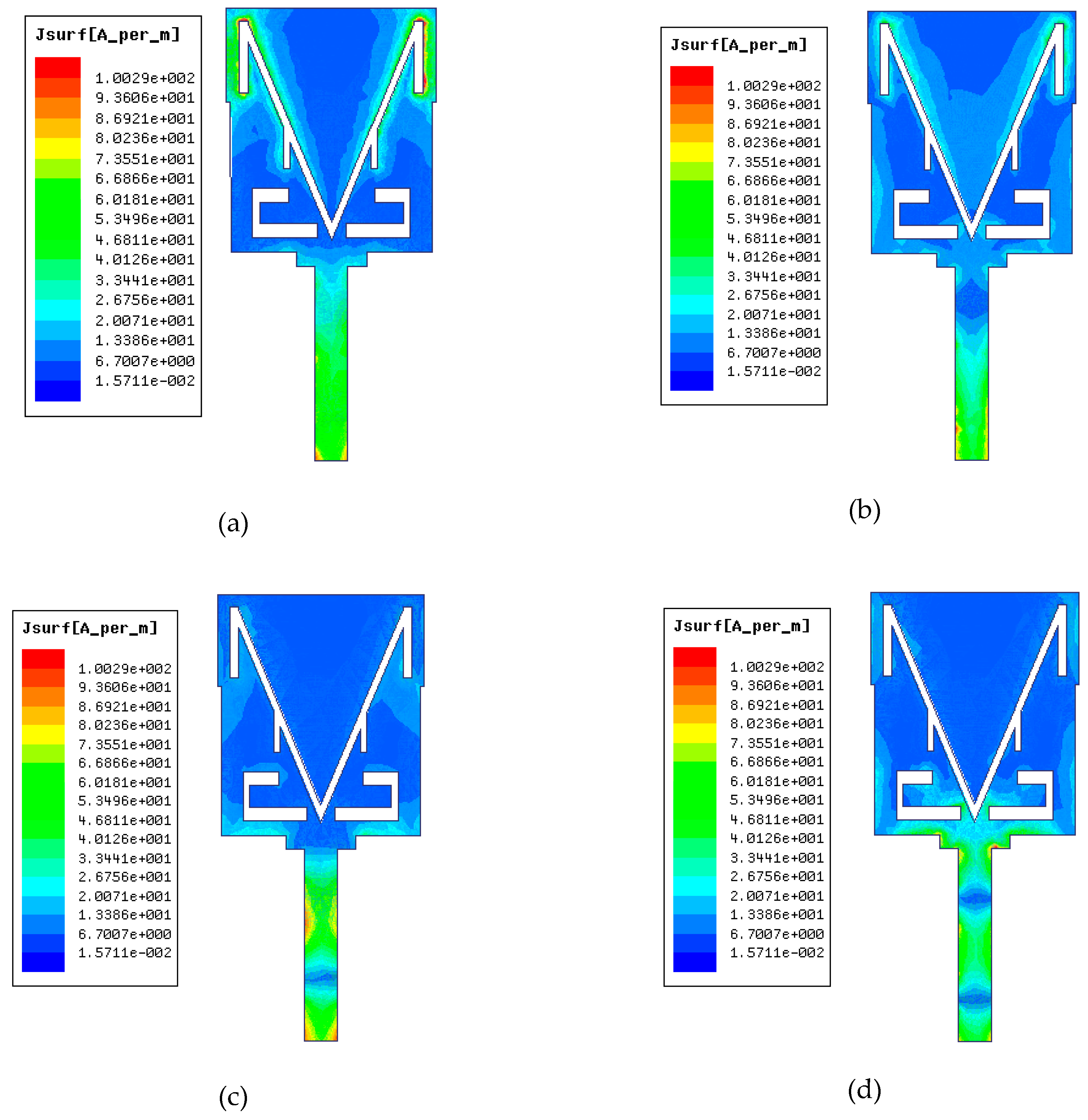
The surface current distributions at the frequencies of 2.48 GHz, 3.5 GHz, 9 GHz, and 11.4 GHz are described in Figure 7. The figure clearly shows that the current distributions are different for all four bands. In particular, when the antenna operates at 2.48 GHz, as shown in Figure 7a, the V-slot with an upper extended slot generates the 2.48 GHz frequency band. In Figure 7b, the current is distributed near the V-slot and between the rectangular slots on the radiation patch. In Figure 7c, the current is mainly distributed at the radiation patch corners and the lower part of the radiation patch at 9 GHz, and in Figure 7d, the current is concentrated on the lower part of the radiation patch and around the rectangular slots. These results show that the concentrations of current on the radiation patch are mainly located around the V-slot for lower frequencies, and for higher frequencies, the current concentrations are mainly located at the corners and bottom part of the radiation patch.
3. Experimental Results and Discussions
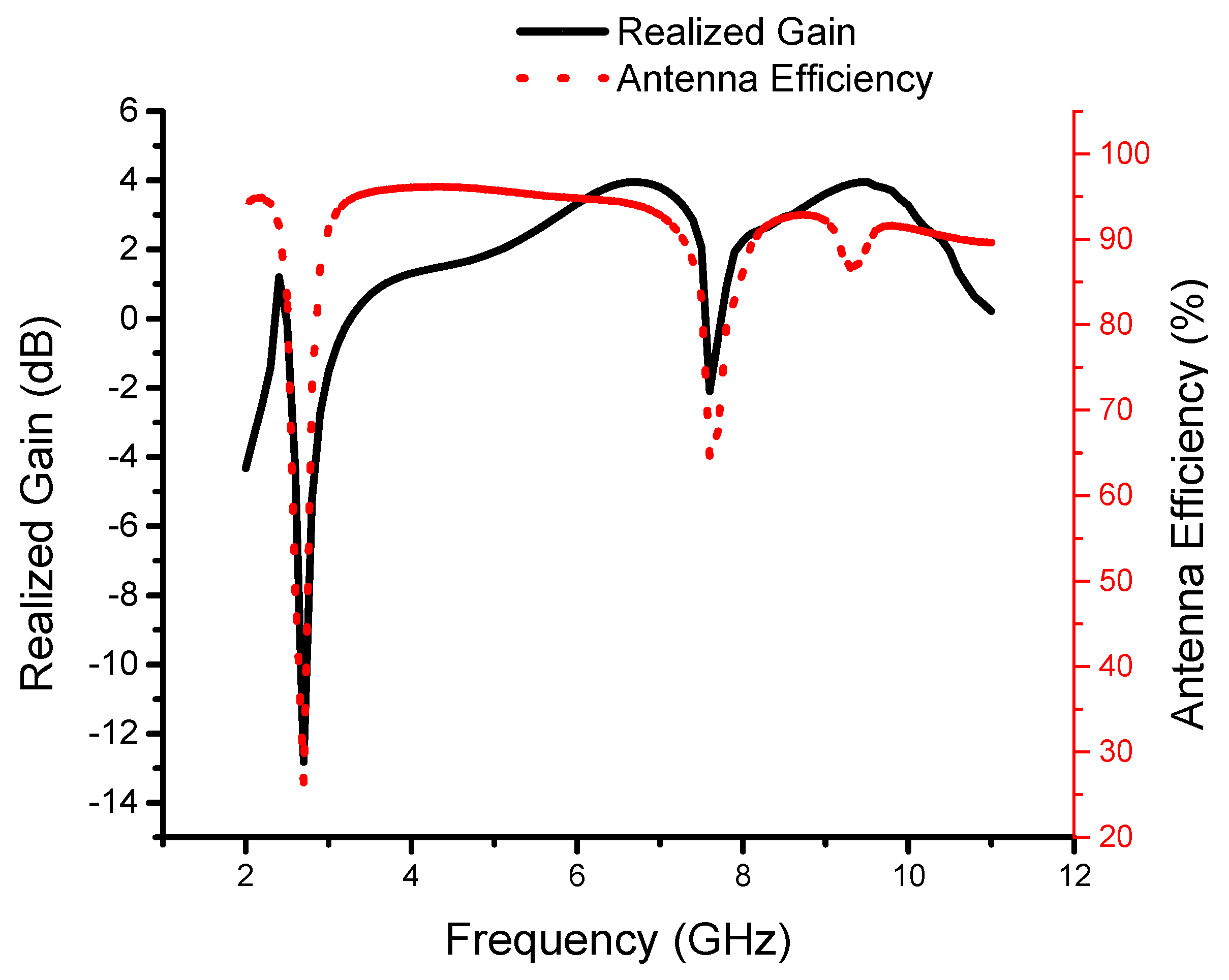
To verify the present antenna model, the proposed monopole MTM antenna is fabricated, as shown in Figure 8. Good agreements between the measurement and simulation S11 results are achieved, as shown in Figure 9. The small difference between the measured and simulated results may be caused by the fabrication tolerance and the SMA connector. The resultant impedance bandwidths of less than −10 dB are 2.38 to 2.57 GHz with a fractional bandwidth of 7.66% for narrowband and 3.2 to 14 GHz, which corresponds to a fractional bandwidth of 144%, for the UWB spectrum. We can observe the presence of the CRLH gap in the simulated and measured results. Figure 10 shows the measured realized gain and antenna efficiency. The realized gain is above 1 dB and the antenna efficiency is above 85% at 2.48 GHz, which is sufficient for short-range communication requirements. It is also observed that a large dip in the realized gain and efficiency occurs at 2.7 GHz. From 3.2 GHz to 14 GHz, the antenna gain is almost flat with a peak gain of 3.9 dB except for near the 8 GHz frequency band. Also, from 3.2 GHz to 14 GHz, the antenna efficiency is almost flat at 90% except for near the 8 GHz frequency band.
3.1. Radiation Characteristics
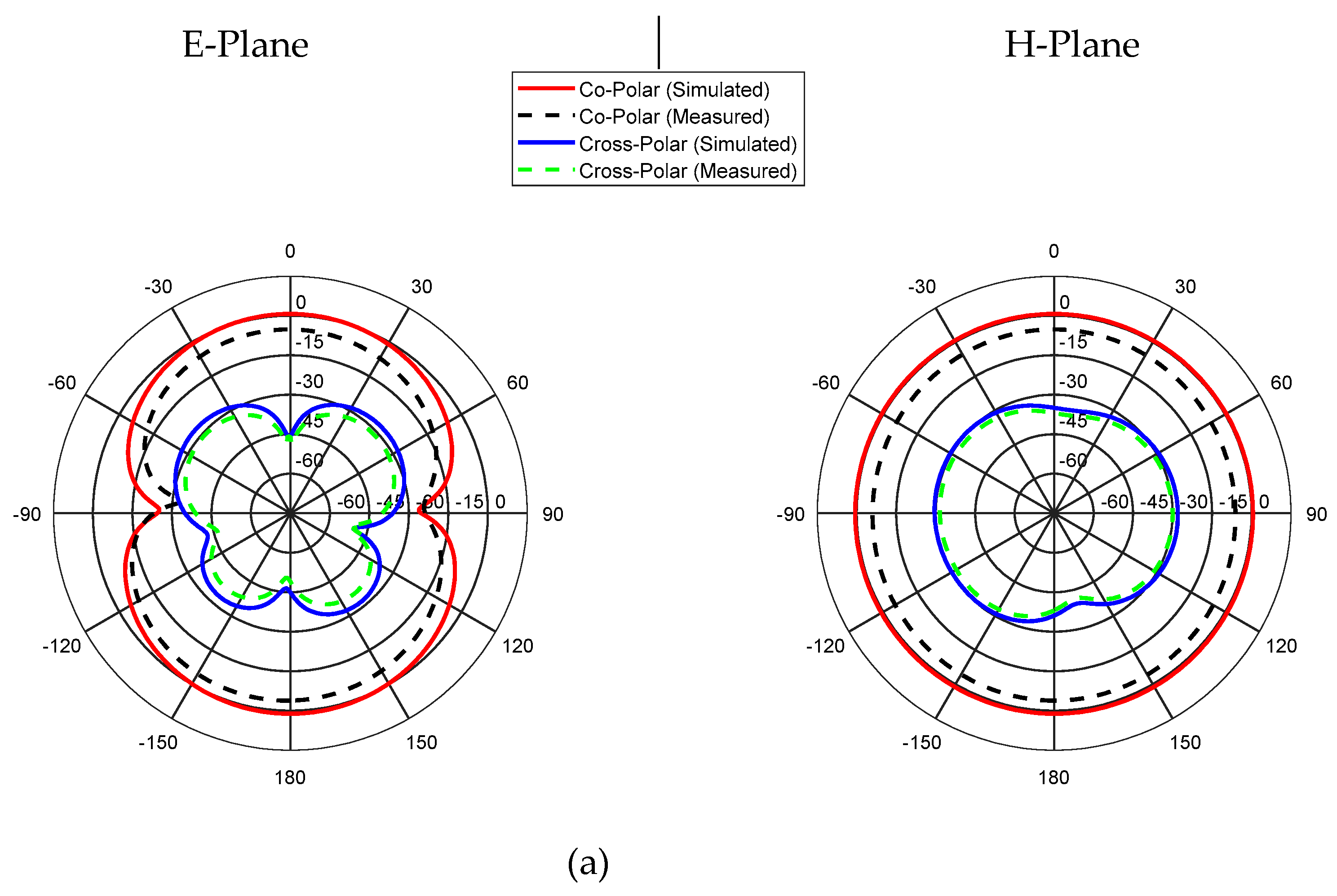
The radiation characteristics of the proposed antenna are shown in Figure 11. The simulated and measured radiation characteristics for the E-plane (yz-plane) and the H-plane (xz-plane) of the antenna are analyzed at three different frequencies; i.e., 2.48, 7, and 11 GHz. There is a good agreement between the measured and simulated results for these frequencies, which indicates that the proposed antenna provides fairly good omnidirectional H-plane patterns and bidirectional E-plane patterns. Additionally, at higher frequencies, the high cross-polarization level is caused by the unequal phase distribution and the significant magnitude of higher-order modes at higher frequencies [23].
3.2. Comparison with Other Reported Designs
A comparison of the proposed monopole UWB antenna with other UWB antennas in terms of the design technique, size, peak gain, and operating band is shown in Table 2. It can be observed from the comparison table that our proposed antenna has some obvious advantages such as a simpler structure, a smaller size, and a wider UWB bandwidth with an extra narrowband.
4. Conclusions
In this paper, a novel dual-band monopole antenna for Wi-Fi and UWB applications is proposed. A narrowband with the UWB band is introduced to combine different short-range communication applications in a single device. By etching and the inclusion of certain slots in the radiation patch, narrowband together with ultrawideband properties are achieved. The antenna is designed and fabricated, and the simulated response is correlated with the measured results. The measurement results indicate that the designed antenna can operate over 2.38 to 2.57 GHz for narrowband and 3.2 to 14 GHz for ultrawideband. The antenna has a nearly omnidirectional radiation pattern, with more than 90% antenna efficiency. The flat gain can meet short-range communication system requirements, which indicates that this antenna has significant potential for Wi-Fi and UWB applications. This antenna demonstrates that it is a good candidate for short-range applications, as this antenna can be easily integrated with portable devices incorporating multiple communication applications.
Author Contributions
A.K. proposed a novel antenna for UWB application. The antenna was optimized through simulation results and then fabricated. Measured results were correlated with simulation results in the writing of the manuscript. R.S. was the head of the research lab, and participated in data analysis. J.D. contributed to the measurement results and paper review.
Funding
This work was supported in part by the National Natural Science Foundation of China under Grant No. 61801521 and 61971450, in part by the Natural Science Foundation of Hunan Province under Grant No. 2018JJ2533, and in part by the Fundamental Research Funds for the Central Universities under Grant No. 2018gczd014 & 20190038020050.
Conflicts of Interest
Authors declare no conflict of interest.
References
- Cheng, G. Accurate TOA-based UWB localization system in coal mine based on WSN. Phys. Procedia 2012, 24, 534–540. [Google Scholar] [CrossRef] [Green Version]
- Bharadwaj, R.; Swaisaenyakorn, S.; Parini, C.G.; Batchelor, J.; Alomainy, A. Localization of wearable ultrawideband antennas for motion capture applications. IEEE Antennas Wirel. Propag. Lett. 2014, 13, 507–510. [Google Scholar] [CrossRef] [Green Version]
- Commission, F. Revision of Part 15 of the Commission’s Rules Regarding Ultra-Wideband Transmission Systems; First Report and Order; Federal Communications Commission: Washington, DC, USA, 2010. [Google Scholar]
- Xu, H.; Yang, L. Ultra-wideband technology: Yesterday, today, and tomorrow. In Proceedings of the IEEE Radio and Wireless Symposium, Orlando, FL, USA, 22–24 January 2008; pp. 715–718. [Google Scholar]
- Mayer, P.; Magno, M.; Schnetzler, C.; Benini, L. EmbedUWB: Low Power Embedded High-Precision and Low Latency UWB Localization. In Proceedings of the 2019 IEEE 5th World Forum on Internet of Things (WF-IoT), Limerick, Ireland, 15–18 April 2019; IEEE: Piscataway, NJ, USA, 2019. [Google Scholar]
- Mirza, A.F.; See, C.H.; Danjuma, I.M.; Asif, R.; Abd-Alhameed, R.A.; Noras, J.M.; Clarke, R.W.; Excell, P.S. An active microwave sensor for near field imaging. IEEE Sens. J. 2017, 17, 2749–2757. [Google Scholar] [CrossRef]
- Silva, B.; Hancke, G.P. IR-UWB-based non-line-of-sight identification in harsh environments: Principles and challenges. IEEE Trans. Ind. Inform. 2016, 12, 1188–1195. [Google Scholar] [CrossRef]
- Li, Q.; Xiao, X.; Song, H.; Wang, L.; Kikkawa, T. Tumor response extraction based on ensemble empirical mode decomposition for early breast cancer detection by UWB. In Proceedings of the 2014 IEEE Biomedical Circuits and Systems Conference (BioCAS) Proceedings, Lausanne, Switzerland, 22–24 October 2014; IEEE: Piscataway, NJ, USA, 2014. [Google Scholar]
- Dawar, P.; Raghava, N.; De, A. UWB Metamaterial-Loaded Antenna for C-Band Applications. Int. J. Antennas Propag. 2019, 2019, 13. [Google Scholar] [CrossRef]
- Alnaiemy, Y.; Lajos, N. Design and analysis of Ultra-Wide Band (UWB) antennas based on metamaterial. In Proceedings of the 2018 11th International Symposium on Communication Systems, Networks & Digital Signal Processing (CSNDSP), Budapest, Hungary, 18–20 July 2018; IEEE: Piscataway, NJ, USA, 2018. [Google Scholar]
- Dawar, P.; De, A.; Raghava, N. S-shaped metamaterial ultra-wideband directive patch antenna. Radioelectron. Commun. Syst. 2018, 61, 394–405. [Google Scholar] [CrossRef]
- Patir, D.; Dipak, K.N. A Uwb Metamaterial Based Patch Antenna For Band Notching And Mimo Application. Int. J. Eng. Sci. Invent. 2018, 7, 53–58. [Google Scholar]
- Alhawari, A.R.; Ismail, A.; Mahdi, M.A.; Abdullah, R.S. Miniaturized ultra-wideband antenna using microstrip negative index metamaterial. Electromagnetics 2011, 31, 404–418. [Google Scholar] [CrossRef]
- Wang, F.; Duan, Z.; Tang, T.; Huang, M.; Wang, Z.; Gong, Y. A new metamaterial-based UWB MIMO antenna. In Proceedings of the 2015 IEEE International Wireless Symposium (IWS 2015), Shenzhen, China, 30 March–1 April 2015; IEEE: Piscataway, NJ, USA, 2015. [Google Scholar]
- Jaglan, N.; Gupta, S.D.; Kanaujia, B.K.; Srivastava, S.; Thakur, E. Triple band notched Dg-Cebg structure based Uwb MIMO/diversity antenna. Prog. Electromagn. Res. 2018, 80, 21–37. [Google Scholar] [CrossRef] [Green Version]
- Dai, Y.L.; Yuan, B.; Zhang, X.H.; Dai, X.W.; Luo, G.Q. A novel compact ultra-wideband metamaterial-based microstrip antenna. In Proceedings of the 2016 IEEE MTT-S International Microwave Workshop Series on Advanced Materials and Processes for RF and THz Applications (IMWS-AMP), Chengdu, China, 20–22 July 2016; IEEE: Piscataway, NJ, USA, 2016. [Google Scholar]
- Roy, B.; Chowdhury, S.K.; Bhattacharjee, A.K. Symmetrical Hexagonal Monopole Antenna with Bandwidth Enhancement under UWB Operations. In Wireless Personal Communications; Springer: Berlin/Heidelberg, Germany, 2019; pp. 1–11. [Google Scholar]
- Ghattas, A.S.W.; Khaled, E.E.M. A compact proximity-fed ultra-wide band patch antenna with four notched-band characteristics: Design and implementation. In Proceedings of the 2014 9th International Symposium on Communication Systems, Networks & Digital Sign (CSNDSP), Manchester, UK, 23–25 July 2014; IEEE: Piscataway, NJ, USA, 2014. [Google Scholar]
- Hammad, Y.T.; Fouda, Z.K.; Abdalla, M.A. An ultra wide band filter with high selective dual notching. In Proceedings of the 2017 IEEE International Symposium on Antennas and Propagation & USNC/URSI National Radio Science Meeting, San Diego, CA, USA, 9–14 July 2017; IEEE: Piscataway, NJ, USA, 2017. [Google Scholar]
- Stefaia, M.; Bergenti, F. Hybride Indoor Localization using WiFi and UWB Technologies. Electronics 2019, 8, 334. [Google Scholar]
- Kołodziej, J.; Grzonka, D.; Widłak, A.; Kisielewicz, P. Ultra Wide Band Body Area Networks: Design and Integration with Computational Clouds. In High-Performance Modelling and Simulation for Big Data Applications; Springer: Berlin/Heidelberg, Germany, 2019; pp. 279–306. [Google Scholar]
- Mandal, T.; Das, S. Design of a microstrip fed printed monopole antenna for bluetooth and UWB applications with WLAN notch band characteristics. Int. J. RF Microw. Comput. Aided Eng. 2015, 25, 66–74. [Google Scholar] [CrossRef]
- Mishra, S.K.; Gupta, R.K.; Vaidya, A.; Mukherjee, J. A compact dual-band fork-shaped monopole antenna for Bluetooth and UWB applications. IEEE Antennas Wirel. Propag. Lett. 2011, 10, 627–630. [Google Scholar] [CrossRef]
- Taheri, M.S.; Mallahzadeh, A.R.; Nezhad, S.M.; Ghasemi, A.H. A compact triple-band fork-shaped printed slot antenna for GSM, Bluetooth and UWB applications. In Proceedings of the 2012 6th European Conference on Antennas and Propagation (EUCAP), Prague, Czech Republic, 26–30 March 2012; IEEE: Piscataway, NJ, USA, 2012. [Google Scholar]
- Cai, L.Y.; Zeng, G.; Yang, H.C.; Cai, Y.Z. Integrated Bluetooth and multi-band ultra-wideband antenna. Electron. Lett. 2011, 47, 688–689. [Google Scholar] [CrossRef]
- Rahman, M.; NagshvarianJahromi, M.; Mirjavadi, S.S.; Hamouda, A.M. Compact UWB Band-Notched Antenna with Integrated Bluetooth for Personal Wireless Communication and UWB Applications. Electronics 2019, 8, 158. [Google Scholar] [CrossRef] [Green Version]
- Yildirim, B.S.; Cetiner, B.A.; Roqueta, G.; Jofre, L. Integrated bluetooth and UWB antenna. IEEE Antennas Wirel. Propag. Lett. 2009, 8, 149–152. [Google Scholar] [CrossRef]
- Yildirim, B.S. Low-profile and planar antenna suitable for WLAN/Bluetooth and UWB applications. IEEE Antennas Wirel. Propag. Lett. 2006, 5, 438–441. [Google Scholar] [CrossRef]
- Bae, J.H.; Jeong, J.G.; Yoon, Y.J.; Kim, Y. A compact monopole antenna for bluetooth and UWB applications. In Proceedings of the 2017 International Symposium on Antennas and Propagation (ISAP), Phuket, Thailand, 30 October–2 November 2017; IEEE: Piscataway, NJ, USA, 2017. [Google Scholar]
- Lai, A.; Itoh, T.; Caloz, C. Composite right/left-handed transmission line metamaterials. IEEE Microw. Mag. 2004, 5, 34–50. [Google Scholar] [CrossRef]
- Liu, C.; Menzel, W. On the relation between composite right-/left-handed transmission lines and chebyshev filters. Int. J. Microw. Sci. Technol. 2009, 2009, 8. [Google Scholar] [CrossRef] [Green Version]
- Li, Z.; Ruan, C.; Peng, L. Design and analysis of planar antenna with dual WLAN band-notched for integrated bluetooth and UWB applications. J. Electromagn. Waves Appl. 2010, 24, 1817–1828. [Google Scholar]
- Zhan, K.; Guo, Q.; Huang, K. A miniature planar antenna for Bluetooth and UWB applications. J. Electromagn. Waves Appl. 2010, 24, 2299–2308. [Google Scholar] [CrossRef]
Figure 1.
Geometry of the proposed antenna: (a) side view; (b) top view; (c) bottom view.

Figure 2.
Antenna radiation patch elements: (a) V-shaped slot; (b) rectangular slot.
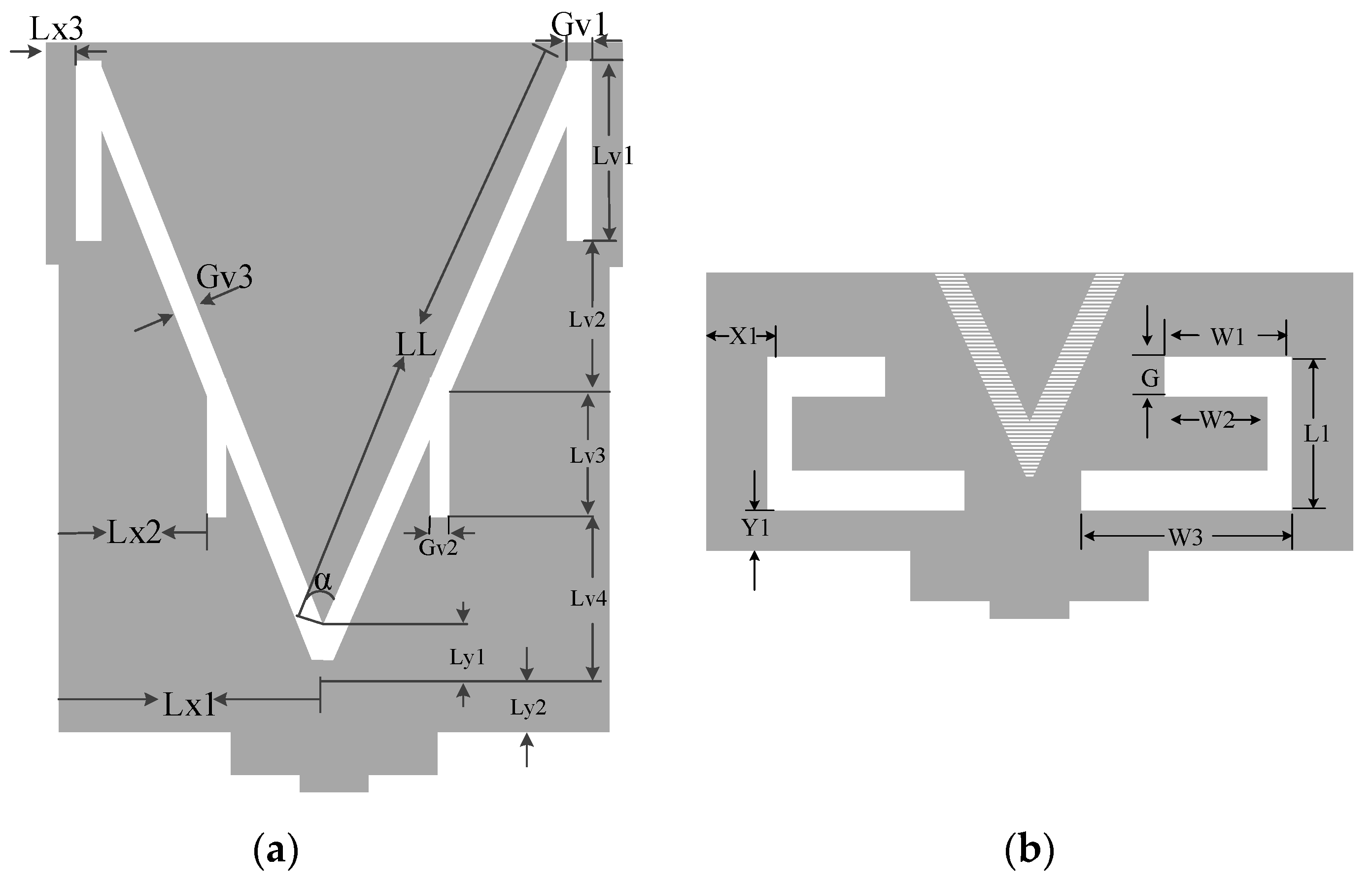
Figure 3.
Balanced and unbalanced cases of the composite right left hand (CRLH) region.

Figure 4.
Performance analysis of radiation patch with and without V-slot.

Figure 5.
Performance analysis of S11 with V-shaped resonant elements: (a) variation of Gv1 for 2.48 GHz (Wi-Fi band); (b) variation of Lv3 for 7.9 GHz (satellite band); (c) variation of Gv1 and Lv3 together.
Figure 5.
Performance analysis of S11 with V-shaped resonant elements: (a) variation of Gv1 for 2.48 GHz (Wi-Fi band); (b) variation of Lv3 for 7.9 GHz (satellite band); (c) variation of Gv1 and Lv3 together.
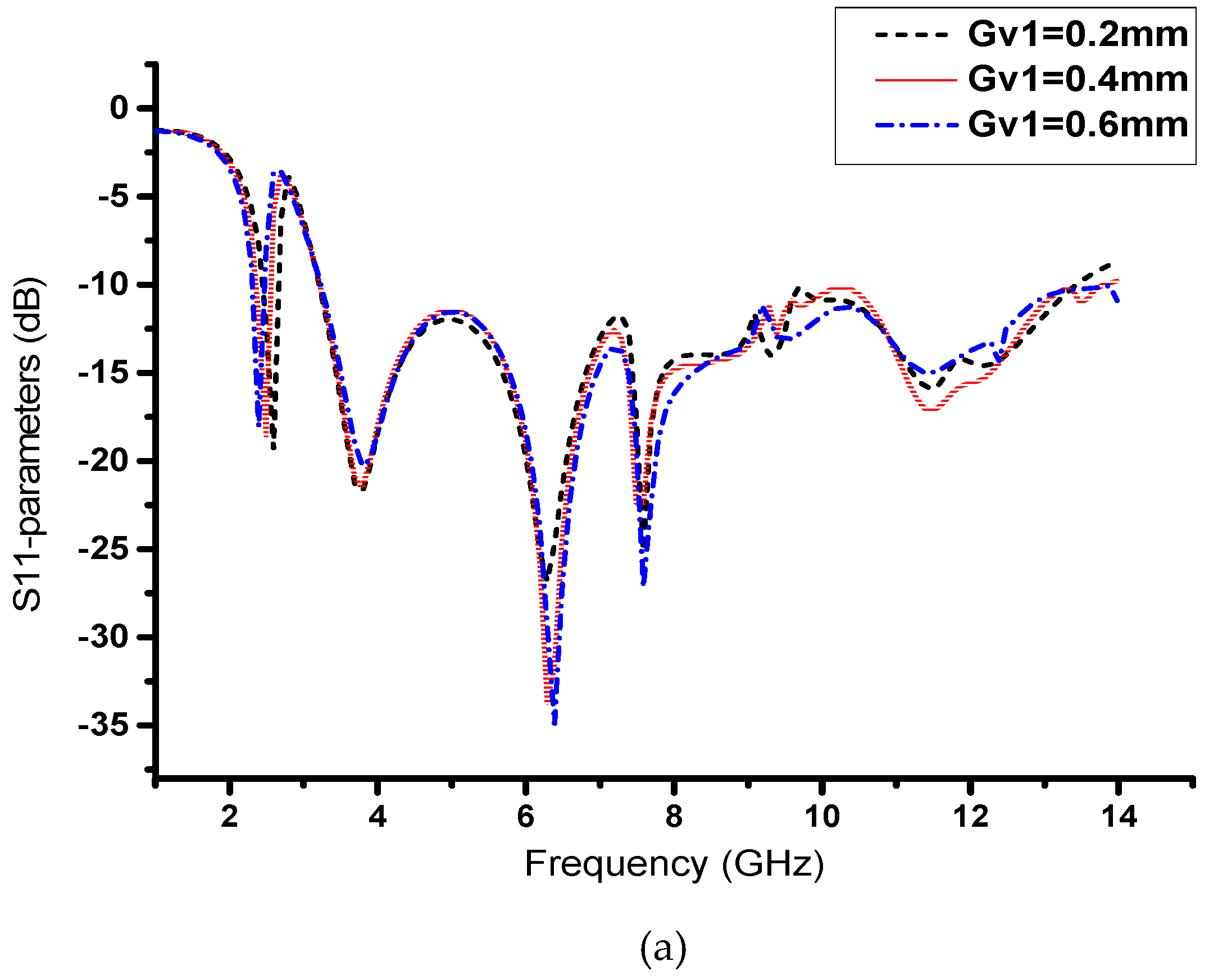

Figure 6.
Performance analysis with different substrate heights.
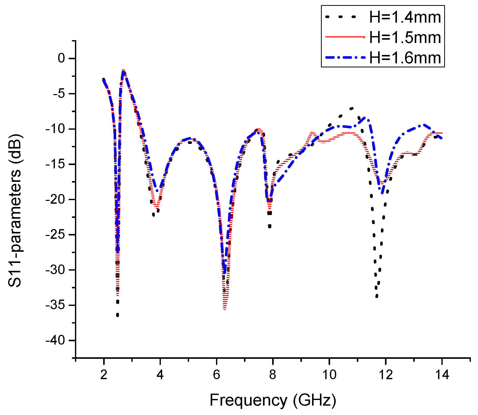
Figure 7.
Surface current distributions on the antenna patch at (a) 2.48 GHz, (b) 3.5 GHz, (c) 9 GHz, and (d) 11.4 GHz.
Figure 7.
Surface current distributions on the antenna patch at (a) 2.48 GHz, (b) 3.5 GHz, (c) 9 GHz, and (d) 11.4 GHz.

Figure 8.
Fabricated proposed antenna prototype, (a) front view and (b) back view.
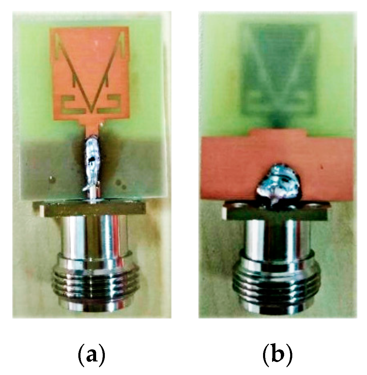
Figure 9.
Simulated and measured S11 results for the proposed antenna.
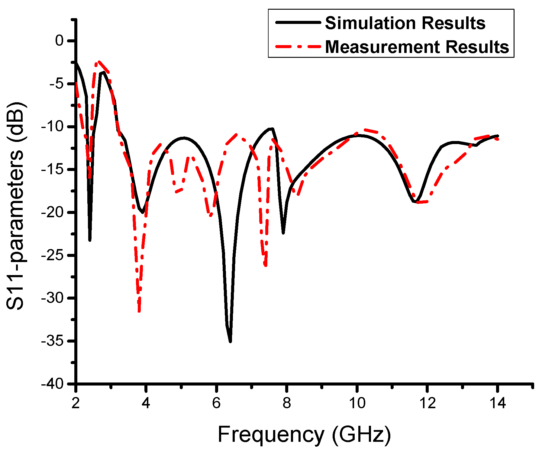
Figure 10.
The measured antenna efficiency and realized gain of the proposed ultrawideband (UWB) antenna.
Figure 10.
The measured antenna efficiency and realized gain of the proposed ultrawideband (UWB) antenna.

Figure 11.
Co- and cross-polar radiation patterns for resonance frequencies of (a) 2.48 GHz, (b) 7 GHz, (c) 11 GHz.
Figure 11.
Co- and cross-polar radiation patterns for resonance frequencies of (a) 2.48 GHz, (b) 7 GHz, (c) 11 GHz.


Table 1.
Design specifications of the proposed antenna structure.
| Parameters | Size (mm) | Parameters | Size (mm) | Parameters | Size (mm) |
|---|---|---|---|---|---|
| LL | 15 | Ly1 | 1.3 | Ly2 | 0.85 |
| Lv1 | 5 | Lv2 | 2.52 | Lv3 | 2.7 |
| Lv4 | 5 | Lx1 | 7 | Lx2 | 3.75 |
| Lx3 | 0.9 | Gv1 | 0.6 | Gv2 | 0.45 |
| Gv3 | 0.5 | α | 46o |
Table 2.
Performance comparison of the proposed antenna with other reviewed antennas. CLS: capacitive loaded strip.
Table 2.
Performance comparison of the proposed antenna with other reviewed antennas. CLS: capacitive loaded strip.
| Reference | Technique | Antenna Size (mm) ( λo = 54 mm) | Antenna peak Gain | Operating band (GHz) | Remarks |
|---|---|---|---|---|---|
| [12] | Octagonal patch with complementary sprit-ring resonator (CSRR) | 25 × 38 × 1.6 (0.46λo × 0.7λo × 0.029λo) | 4.6 dB | 3.2–9.2 | Without narrow band |
| [13] | Octagonal spiral resonator (OSR), Octagonal SRR (OSRR) and CLS resonators | 25 × 25 × 1.6 (0.46λo × 0.46 λo × 0.029λo) | 3.9 dB | 5.2–13.9 | Without narrow band |
| [14] | Rectangular patch | 15 × 30 × 1 (0.27λo × 0.55λo × 0.018λo) | / | 3.1–10 | Without narrow band |
| [15] | Semicircular stepped resonator | 58 × 45 × 1.6 (1.07λo × 0.83λo × 0.018λo) | 10 dB | 3.1–10 | Large antenna size with a long rectangular shape without Wi-Fi band |
| [16] | Meshed top patch & patterned ground plane | 28 × 32 × 0.79 (0.51λo × 0.59λo × 0.014λo) | 5.8 dB | 3.1–12 | Without narrow band |
| [17] | Hexagonal patch with defected ground plane | 20 × 25 × 1.6 (0.37λo × 0.46λo × 0.029λo) | 5.1 dB | 3.09–12.2 | Without narrow band |
| [18] | Cedar tree-shaped | 20 × 20 × 1.6 (0.37λo × 0.37λo × 0.029λo) | 5.5 dB | 3–11.7 | Without narrow band |
| [22] | Resonating monopole strip loaded at the center of the patch | 52 × 32 × 1.59 (0.96λo × 0.59λo × 0.029λo) | 7 dB | 3.1–11.4 & 2.31-2.59 | Large antenna size with long rectangular shape |
| [24] | Loaded with a quarter-wavelength resonating strip | 42 × 24 × 1.6 (0.77λo × 0.44λo × 0.029λo) | 5 dB | 3.1–12 & 2.3–2.5 | Large antenna size with long rectangular shape |
| [26] | Capacitor loaded miniaturized resonator in the ground plane | 30 × 31 × 1.5 (0.55λo × 0.57λo × 0.027λo) | 6dB | 3.1–10.6 & 2.4–2.48 | Complex structure and relatively small operational bandwidth |
| [27] | L-shaped stub | 46 × 42 × 1 (0.58λo × 0.77λo × 0.018λo) | 2.81 dB | 3.1–10.6 & 2.4–2.48 | Large antenna size with long Bluetooth element |
| [28] | Loaded with long Bluetooth strip | 16 × 28 × 1 (0.29λo × 0.51λo × 0.018λo) | 6 dB | 4.5–11 & 2.4–2.48 | Incomplete operational UWB spectrum |
| [29] | Parasitic stub, branch line, and meander line | 19 × 28 × 0.8 (0.35λo × 0.51λo × 0.014λo) | / | 3.1–10.6 & 2.4–2.48 | Complex structure and relatively small operational bandwidth |
| [32] | Loaded with parasitic strip | 46 × 20 × 1 (0.85λo × 0.37λo × 0.018λo) | 4.2 dB | 3.1–10.6 & 2.4–2.48 | Large antenna size with long rectangular shape |
| [33] | Strip-line and cutting ground plate | 45 × 32 × 1 (0.83λo × 0.59λo × 0.018λo) | 3.5 dB | 3.1–10.6 & 2.4–2.5 | Large antenna size with long rectangular shape |
| Proposed antenna | Loaded with V-shaped slot | 27 × 33 × 1.5 (0.5λo × 0.61λo × 0.027λo) | 3.9 dB | 3.2–14 & 2.38–2.57 | simple and compact size with wider operational bandwidth |
© 2019 by the authors. Licensee MDPI, Basel, Switzerland. This article is an open access article distributed under the terms and conditions of the Creative Commons Attribution (CC BY) license (http://creativecommons.org/licenses/by/4.0/).
Share and Cite
MDPI and ACS Style
Khurshid, A.; Dong, J.; Shi, R. A Metamaterial-Based Compact Planar Monopole Antenna for Wi-Fi and UWB Applications. Sensors 2019, 19, 5426. https://doi.org/10.3390/s19245426
AMA Style
Khurshid A, Dong J, Shi R. A Metamaterial-Based Compact Planar Monopole Antenna for Wi-Fi and UWB Applications. Sensors. 2019; 19(24):5426. https://doi.org/10.3390/s19245426
Chicago/Turabian StyleKhurshid, Adnan, Jian Dong, and Ronghua Shi. 2019. "A Metamaterial-Based Compact Planar Monopole Antenna for Wi-Fi and UWB Applications" Sensors 19, no. 24: 5426. https://doi.org/10.3390/s19245426
Note that from the first issue of 2016, this journal uses article numbers instead of page numbers. See further details here.