A Frequency Signature RFID Chipless Tag for Wearable Applications


Department of Engineering for Innovation, University of Salento, via per Monteroni, 73100 Lecce, Italy
*
Author to whom correspondence should be addressed.
Sensors 2019, 19(3), 494; https://doi.org/10.3390/s19030494
Submission received: 21 December 2018
/
Revised: 21 January 2019
/
Accepted: 22 January 2019
/
Published: 25 January 2019
(This article belongs to the Special Issue Passive Electromagnetic Sensors for Autonomous Wireless Networks)
Abstract
:In this paper, a frequency-signature Radio-Frequency Identification (RFID) chipless tag for wearable applications is presented. The results achieved for a fully-textile solution guaranteeing a seamless integration in clothes are reported and discussed. The proposed tag consists of two planar monopole antennas and a 50 Ω microstrip line loaded with multiple resonators. In order to achieve a compact size, the resonators are slotted on the ground plane of the microstrip line. As for the antennas, the same geometry was exploited for both the TX and the RX tag antenna. In particular, it consists of a proximity fed planar monopole on a ground plane. The selected geometry guarantees easy integration with the multi-resonator structure. Numerical and experimental data referring to a 2-bit implementation are presented and discussed. For fabricating all the prototypes, a layer of pile was used as a substrate, while an adhesive non-woven conductive fabric was exploited for the fabrication of the conductive parts. Experimental tests demonstrate that although the performance of the final device strongly depends on the properties of the used materials and on the imperfections of the fabrication process, the proposed frequency-signature RFID chipless tag is suitable for wearable applications, such as anti-counterfeiting systems and laundry labels.
1. Introduction
So far, the success of wearable electronics has been hampered by technological limits and, in particular, by the lack of materials and manufacturing techniques that would enable a seamless integration of the electronic parts in the garments. In fact, although several conductive fabrics are available on the market [1,2,3] and different low-cost fabrication techniques have been proposed in literature [3,4,5,6,7,8,9,10,11,12,13,14,15], the wearability of smart clothes and their robustness in operations such as washing, drying and ironing are still strongly limited by the use of chips and ICs requiring tin soldering [5,6]. This problem is overcome by chipless devices, such as chipless Radio Frequency Identification (RFID) tags [16,17,18,19,20,21,22,23,24,25,26,27,28,29,30,31,32,33,34].
The use of chipless tags guarantees important practical advantages, such as seamless integration with the clothes, real-time operations, potentially infinite “service-life”, low environmental impact, and low cost [16,17,18]. Furthermore, chipless tags are able to work in harsh scenarios where the correct operation of conventional RFID technology could be compromised by the exposure of ICs to high temperatures or hazardous environments [16]. On the other hand, encoding data without the presence of ICs represents a major challenge. For this reason, industrial and academic efforts are mainly focused on the investigation of new approaches guaranteeing efficient encoding [16].
More recently, the chipless RFID technology has also been exploited for the fabrication of sensors [16,18,23,25,26,27,28]. In this regard, numerous chipless sensors have been proposed in the literature, but for the majority of these devices, reliability and reproducibility are still critical issues [18].
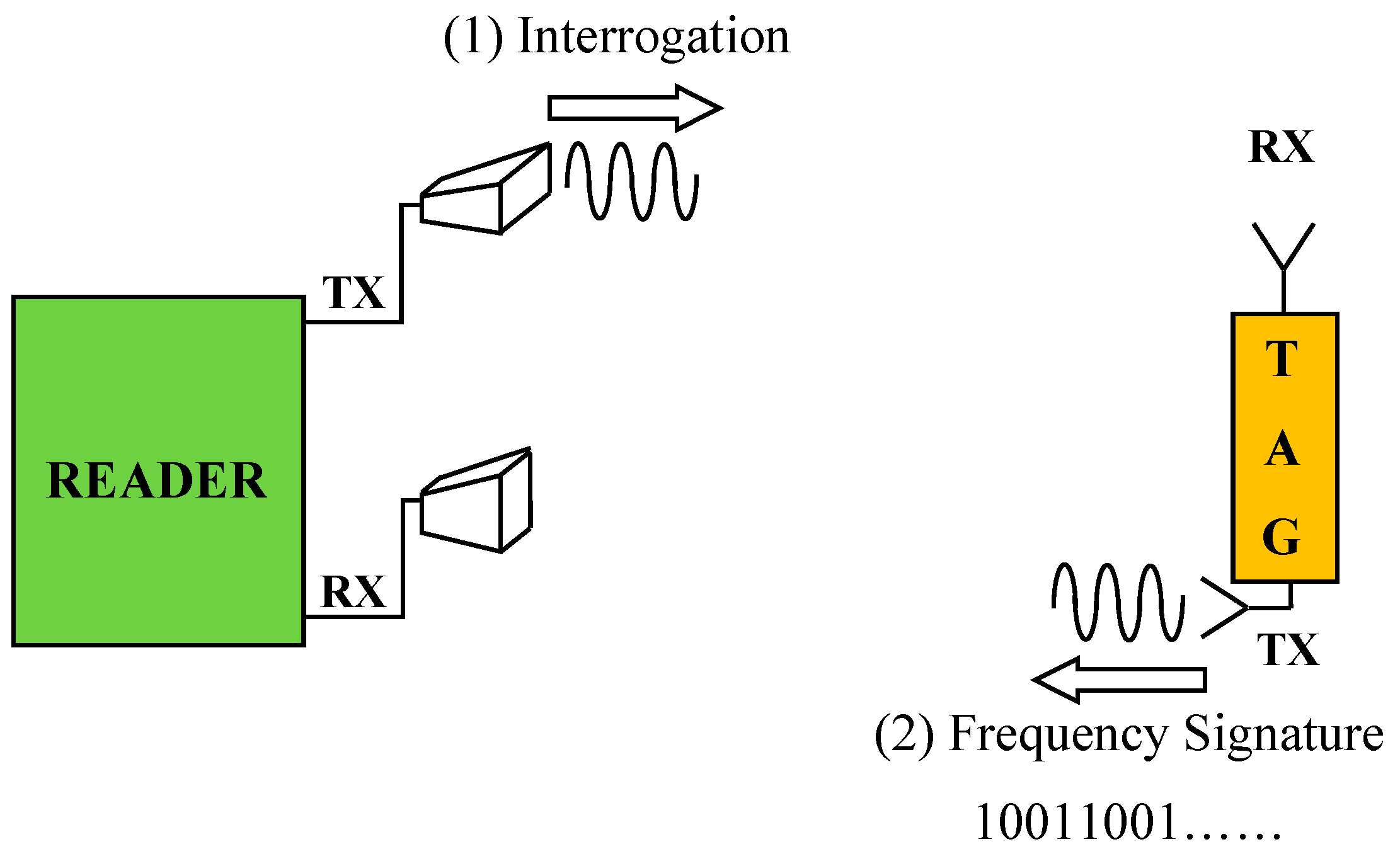
In terms of the approach adopted for encoding data, the following classification can be used for RFID chipless tags: spectral signature [19], phase encoding [29], polarization diversity [30], and time domain signature [31]. However, aside from the adopted approach, the operating mechanism is the same: there is a reader that sends an interrogation signal to the transponders; the transponders reflect back a signal encapsulating the encoded data (see Figure 1).
As for wearable applications, both simple chipless tags and sensors have been proposed in the literature [23,24,32,33,34]. Among these, in [23], the results achieved for a sewn chipless RFID sensor tag are presented. Numerical and experimental results reported in the paper demonstrate the correct operation of the chipless tag in the frequency range, 3–6 GHz. In more detail, the sewn stretchable sensor consists of a rectangular loop sewn on to a stretchable fabric. A conductive thread is used for fabricating the loop. The achieved results confirm that the proposed device is suitable to be used as a strain sensor.
In Reference [24], an RFID chipless tag for people identification is presented. The proposed device consists of L-shaped scatterers able to depolarize the incident wave and to generate a cross-polarized signal. The capability of depolarizing the interrogation signal allows for a robust decoding even when the tag is placed in direct contact with the human body. However, numerical and experimental results demonstrate that the performance of the proposed tag is strongly affected by bending. In particular, a wrong ID decoding occurs if the tag is placed on a curved region of the human body.
In Reference [33], the authors have proposed a fully textile frequency-signature chipless tag consisting of a microstrip line loaded with multiple resonators. Each resonator corresponds to a single bit. Numerical and experimental results achieved for a 3-bit prototype have demonstrated the suitability of the proposed device for RFID wearable applications requiring a low number of bits, such as anti-counterfeiting systems and laundry labels [23]. In this paper, new numerical and experimental results are reported and discussed. It is shown that the proposed device is a low-cost solution which allows a seamless integration in garments.
The paper is structured as follows: in Section 2, details on the geometry and numerical results achieved for both the single components (adjustable multi-stopband structure and monopole antennas) and the tag connected with antennas are given, experimental results are reported in Section 3, and finally, a brief discussion and some conclusions are reported in Section 4.
2. Geometry and Numerical Results
The proposed wearable frequency-signature chipless tag consists of a 50 Ω microstrip line loaded with compact resonators and two wideband antennas. In particular, the microstrip line acts as a stopband structure.
As shown in Figure 1, a generic RFID system based on a multi-resonator tag also comprises a reader equipped with two antennas. The operating principle is very simple: (1) the reader sends an interrogation signal to the tag and (2) the tag replies, sending a backscattered signal whose frequency spectrum contains the encoded data. Both the reader and the transponder antennas are cross-polarized in order to minimize possible interferences between the interrogation signal and the backscattered encoded signal [19]. In this paper, the attention is focused on the tag system.
In the following subsections, details on the geometry and numerical results achieved for both the single components (adjustable multi-stopband structure and wideband antennas) and the overall tag system will be given.
2.1. Multi-Resonator Structure
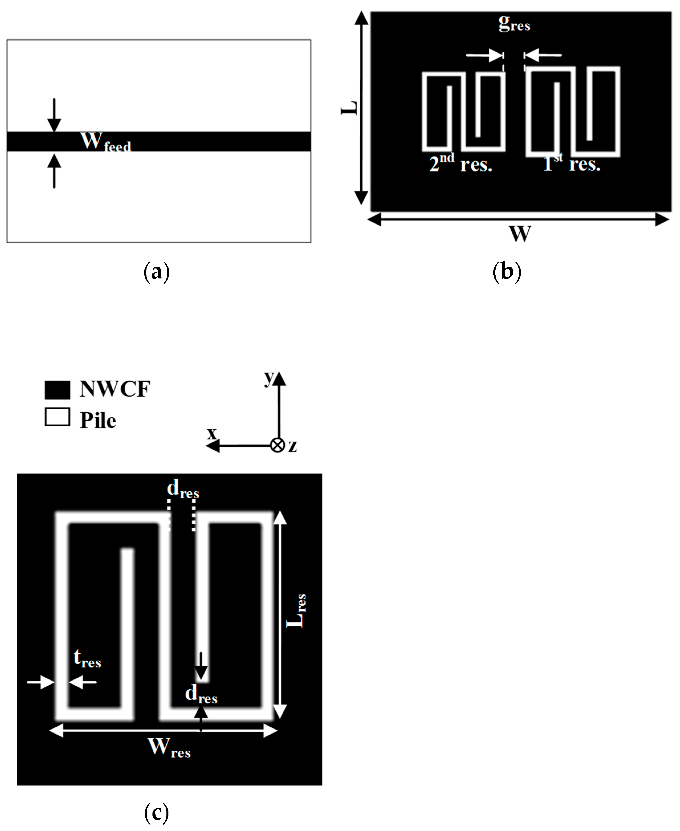
The proposed multi-resonator structure is illustrated in Figure 2. The resonators are slotted on the ground plane of the microstrip line. The front view and the back view of a 2-bit multi-stopband structure are shown in Figure 2a,b, respectively; the single resonator is illustrated in Figure 2c.
The design of the multi-stopband structure was performed with the commercial full-wave simulator CST Microwave Studio [35]. The design process consisted of two main steps: 1) first, the resonator operating at the lowest frequency was optimized; 2) second, the resonators operating at higher frequencies were obtained through a uniform scaling of the first resonator on the x–y plane. The adopted approach can be summarized through the following equation, which describes the relationship between the total area of the first resonator and the total area of the nth resonator:
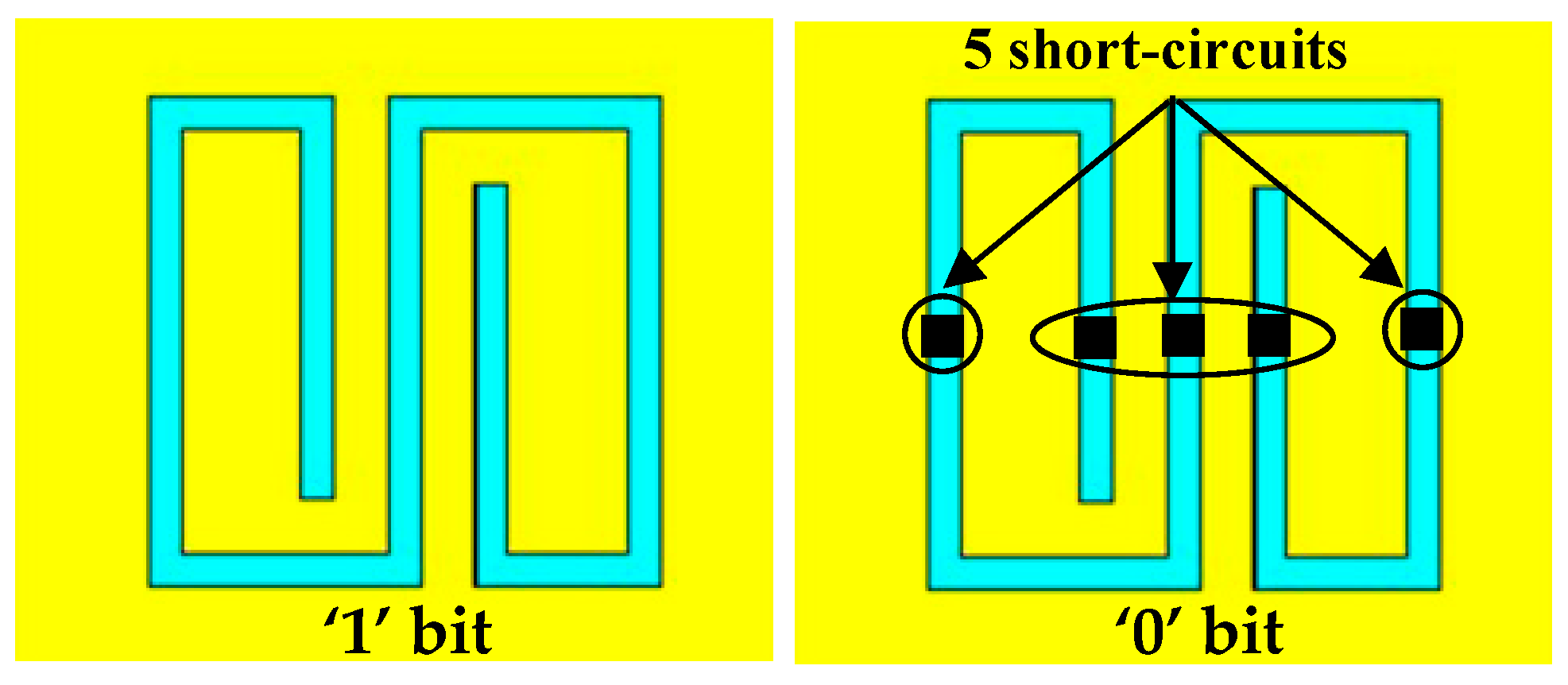
where A1 is the area of the first resonator (on the x–y plane), An is the area of the nth-resonator (on the x–y plane), and SFn is the nth scale factor. Each resonator introduces a transmission zero (i.e., a relative minimum of the transmission coefficient of the microstrip line), whose central frequency is controlled by the parameter SFn. Consequently, each resonator corresponds to a single bit and the presence of a minimum amplitude (and a phase variation) of the S21 parameter represents a logic 1; conversely, the absence is encoded as a “0” bit. To encode a logic 0, the layout of the corresponding resonator is modified as illustrated in Figure 3.
The frequency shift between two consecutive resonant peaks depends on the scale factor and, obviously, for a given bandwidth, higher scale factors allow a higher number of bits to be encoded; on the other hand, excessively high scale factors lead to a complex decoding.
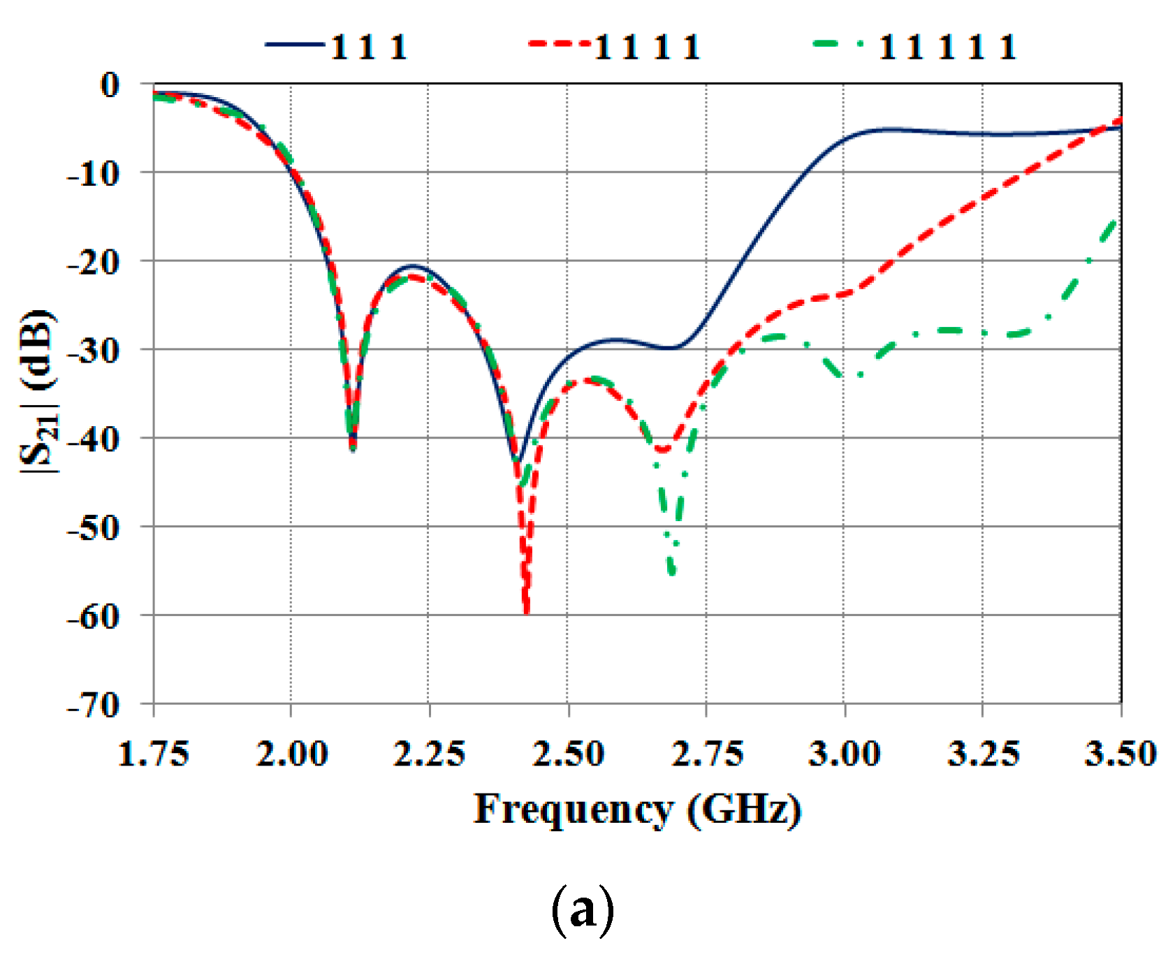
A comparison between numerical results achieved for multi-resonator structures having a different number of bits is illustrated in Figure 4a.
Numerical results obtained for four different configurations of a 3-bit tag are reported in Figure 4b,c. These results demonstrate that the data encapsulated in the frequency spectrum can be decoded by analyzing both the amplitude (Figure 4a,b) and the phase (Figure 4c) of the S21 parameter.
As it can be seen from Figure 4b,c, for the different configurations, the position of the minima of the |S21| and of the phase variations of the S21 are both stable in frequency. This means that when the geometry of one or more resonators is modified to achieve a logic 0, the resonances corresponding to the other resonators are not significantly influenced.
2.2. TX and RX tag Antennas
As shown in Figure 1, a multi-resonator chipless tag also includes TX and RX antennas. Hence, to complete the geometry of the proposed device, two planar monopole antennas were also designed. The geometry adopted for the TX and the RX antennas, which is illustrated in Figure 5, was proposed for the first time in [36]. Each antenna is a proximity-fed planar monopole on a ground plane, optimized to operate in the frequency range 2–4 GHz. This solution guarantees a compact size and simplifies the integration with the multi-stopband structure. As required by any multi-resonator chipless tag RFID system (see Figure 1), the two antennas are cross-polarized; in particular, the RX antenna is y-polarized (see Figure 5a), while the TX antenna is x-polarized (see Figure 5b). The final dimensions of the two antennas are summarized in Table 1.
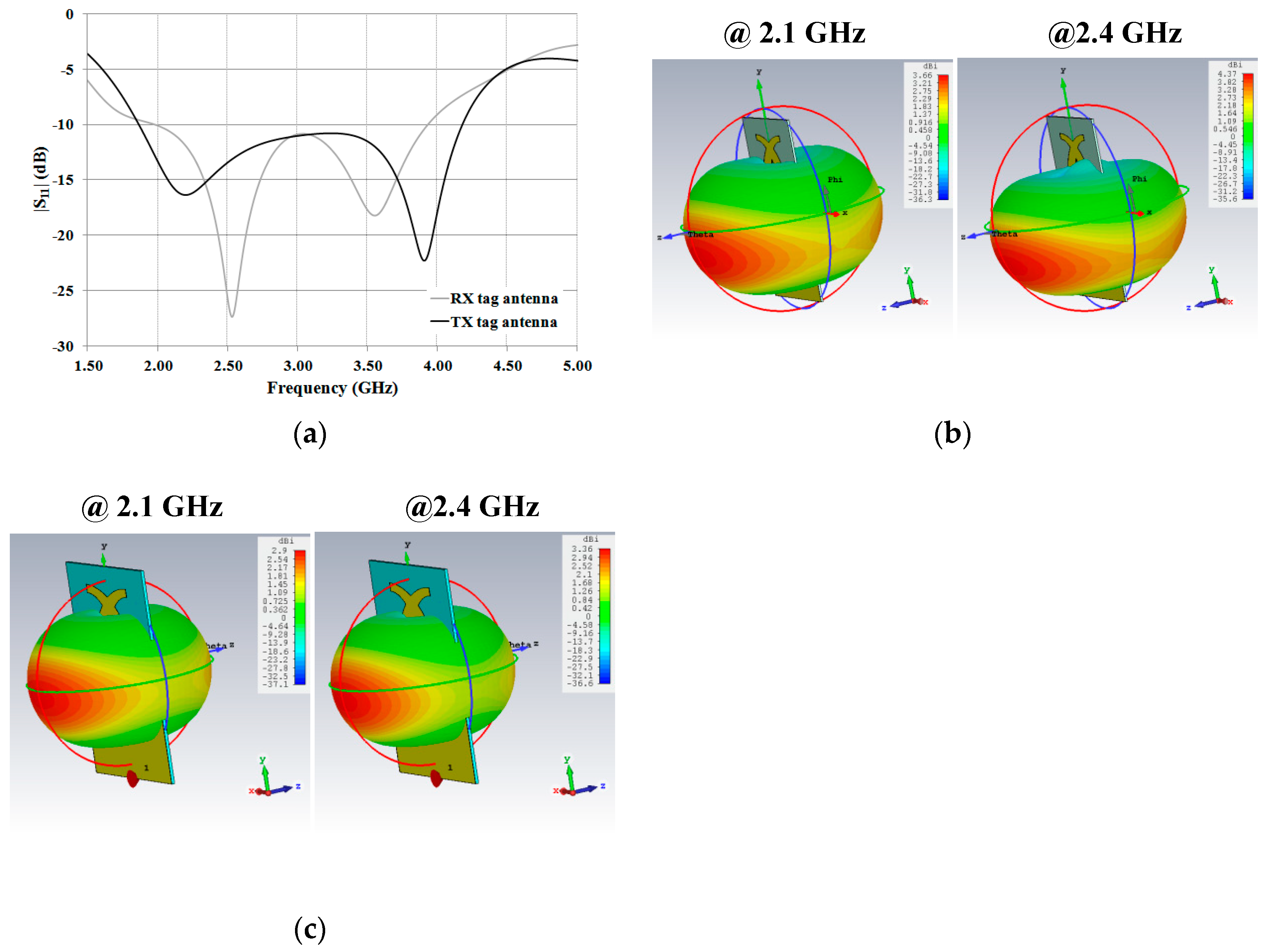
Numerical results achieved for the reflection coefficient are reported in Figure 6a. As for the RX antenna, values of the |S11| lower than –10 dB were achieved in the frequency range 1.97–3.93 GHz, corresponding to a relative bandwidth of about 66.4 %. Meanwhile, the TX antenna exhibits an |S11| lower than –10 dB in the range 1.86–4.20 GHz, corresponding to a relative bandwidth of about 80.7 %.
As for the radiation properties, values of directivity higher than 2 dBi and a dipole-like radiation pattern were achieved in the –10 dB relative bandwidth. 3D radiation patterns calculated at 2.1 GHz and 2.4 GHz are illustrated in Figure 6b,c. Finally, all of the achieved numerical results are summarized in Table 2.
2.3. Overall System Tag
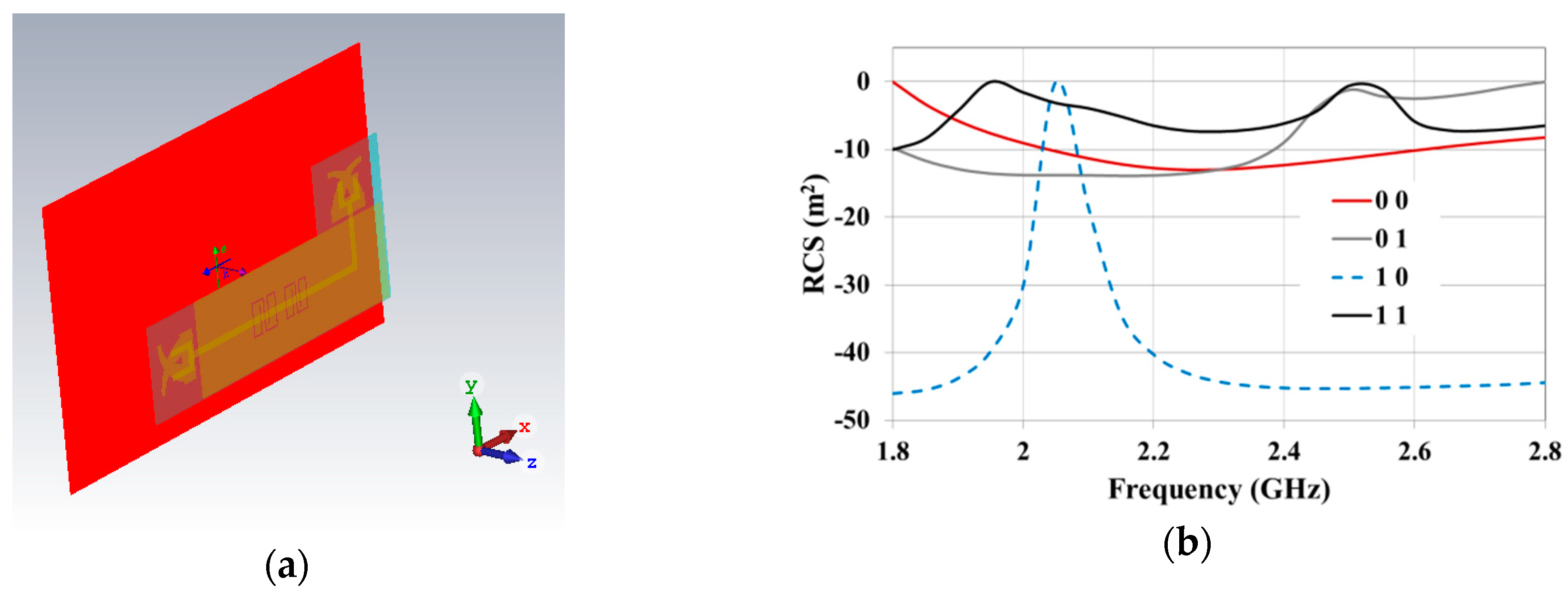
Full-wave simulations were also performed in order to evaluate the performance of the overall tag system (i.e., the multi-stopband structure integrated with the TX and the RX tag antennas) in the case of a 2-bit configuration. The whole device is illustrated in Figure 7a. A plane wave was used as a source. According to the polarization of the RX tag antenna, the E-field was y-polarized. The results achieved for the Radar Cross Section (RCS) are illustrated in Figure 7b. In this case, a relative maximum of the RCS corresponds to a logic 1. As can be noticed, good results were obtained for the second bit, i.e., the one corresponding to the resonator having a higher frequency of resonance. In fact, for the second bit, it can be seen that the frequency at which the RCS maximum is positioned is stable (the same frequency was obtained for the configurations 11 and 01), and a difference higher than 10 dB can be observed between the RCS amplitudes corresponding to the two logical states. As per the first bit, it can be seen that the first relative maximum of the RCS is positioned at a different frequency for the configuration 11 and 10. However, also in this case, the two logical states can be easily recognized; in fact, a difference of about 10 dB was obtained for the amplitude of the RCS corresponding to the two states.
3. Experimental Results
In order to verify the numerical data presented in the previous Section, some prototypes were realized and characterized. In more detail, three different prototypes were fabricated: 1) a prototype of the stop-band microstrip line in a 2-bit configuration; 2) a prototype of the TX and the RX antennas; 3) a prototype of the stopband microstrip line integrated with the RX antenna. The achieved results are described in the following. All the results refer to an implementation on a layer of pile with 0.5 mm thickness, and by using an adhesive non-woven conductive fabric for all the conductive parts.
3.1. Stop-Band Microstrip Line
In Reference [33] the authors presented the results referring to a stopband microstrip line in a 3-bit configuration (i.e., the configuration having three resonators slotted on the ground plane). The achieved experimental results were slightly different to the numerical ones. From the foregoing analysis, it was concluded that the mismatch between numerical and experimental results obtained for the 3-bit configuration was likely due to some imperfections of the fabrication process. In particular, the prototype presented in Reference [33] was fabricated on a 1 mm layer of pile achieved by sewing two layers, 0.5 mm thick. By analyzing the prototype, it was verified that the hand-stitching led to a non-uniform thickness of the pile. Additionally, further imperfections were introduced by the cutting plotter used for shaping the non-woven conductive fabric; in fact, the adopted plotter is more suitable for processing small areas.
Taking into account these considerations, to avoid the hand-sticking and to have a smaller area to be processed, the prototype presented in this paper is a stopband microstrip line in a 2-bit configuration fabricated on a single layer of pile (thickness 0.5 mm, dielectric permittivity equal to 1.18). As in Reference [33], an adhesive non-woven conductive fabric produced by Saint Gobain was used for all the conductive parts and a cutting plotter was used for the fabrication [9,10].
The final geometrical parameters of the prototype are reported in Table 3. The scale factor (see Equation (1)) was optimized for achieving a resonance shift of about 300 MHz. In particular, the two resonators were designed to introduce two stopbands centered at 2.1 GHz and 2.4 GHz.
A picture of the 2-bit prototype is reported in Figure 8a. Experimental tests were performed through a VNA R&S ZVA50. The results for both the amplitude and the phase of the S21 parameter are illustrated in Figure 8b,c, respectively. A good agreement between the numerical data and experimental results was achieved. In particular, the first minimum of the |S21| is centered at 2.08 GHz and the second one at 2.40 GHz. Hence, with respect to the numerical data, there is a shift of about 20 MHz for the resonance corresponding to the first resonator; while the resonance of the second resonator is perfectly tuned. These results confirm that, as supposed by the authors, the disagreement between numerical data and experimental results achieved in Reference [33] was mainly due to some imperfections in the manufacturing process such as irregular thickness of the pile and cutting plotter, unsuitable to process large area.
3.2. TX and RX Tag Antennas
In order to verify the numerical data of the antennas presented in the previous section, a prototype of both the TX and the RX antenna using the dimensions reported in Table 1 was fabricated (see Figure 9a,b). The experimental results achieved for the reflection coefficients are reported in Figure 9c. In both cases, a good agreement between the numerical and experimental results was obtained. From Figure 9c, it can be seen that both of the antennas exhibit values of the reflection coefficient lower than –10 dB in the frequency range of interest (i.e., 2–3 GHz).
3.3. 2-Bit Tag
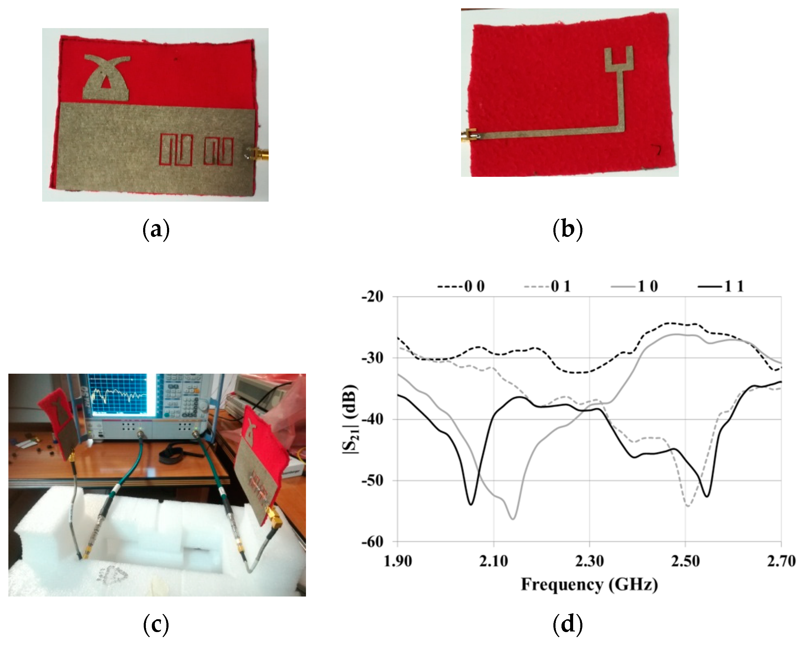
Finally, a prototype of the stopband microstrip line integrated with the RX antenna was realized (Figure 10a,b). The overall dimensions of the prototype are 85.9 mm X 110 mm. The expected performance was verified by adopting the setup illustrated in Figure 10c.
In more detail, two-port measurements were performed with the antenna illustrated in Figure 9b connected to Port 1 and the microstrip line integrated with the RX antenna connected to Port 2.
The transmission coefficient measured for all of the configurations of interest is reported in Figure 10d. As can be noticed, the results are very promising; in fact, even though the positions of the relative minima of the transmission coefficient are slightly different for different configurations (see, for instance, the position of the first minimum for the configurations 11 and 10), the presence of a logic 0 or a logic 1 can be easily recognized.
It would probably be possible to further improve the results by optimizing the geometry of the antennas and the transition between the stopband structure and the antenna feed-line. However, the results shown in Figure 10d fully demonstrate the feasibility of the proposed design approach and of its fully textile implementation.
4. Conclusions
In this paper, a fully textile frequency-signature RFID chipless tag was presented. The proposed tag encodes the desired information by exploiting a microstrip line loaded with multiple resonators slotted on the ground plane. Each resonator introduces at its frequency of resonance a relative minimum on the transmission coefficient of the microstrip line. Accordingly, by designing the resonators to have different frequencies of resonance, it is possible to encapsulate the binary code in the frequency signature of the microstrip line.
As for the antennas, the same geometry of a planar broadband monopole was applied to both the transmitting and the receiving tag antenna.
Experimental data demonstrate the feasibility and good perspectives of the proposed design approach and of its fully textile implementation.
Author Contributions
Conceptualization, L.C., G.M. and L.T.; Methodology, L.C, G.M. and L.T..; Validation, L.C.; Formal Analysis, L.C., G.M and L.T.; Investigation, L.C., G.M and L.T.; Data Curation, L.C.; Writing-Original Draft Preparation, L.C.; Writing-Review & Editing, G.M. and L.T.; Visualization, L.C.; Supervision, G.M. and L.T.
Funding
This research received no external funding.
Conflicts of Interest
The authors declare no conflict of interest.
References
- Liu, N.; Lu, Y.; Qiu, S.; Li, P. Electromagnetic properties of electro-textiles for wearable antennas applications. Front. Electr. Electron. Eng. Chin. 2011, 6, 563–566. [Google Scholar] [CrossRef]
- Salvado, R.; Loss, C.; Gonçalves, R.; Pinho, P. Textile Materials for the Design of Wearable Antennas: A Survey. Sensors 2012, 12, 15841–15857. [Google Scholar] [CrossRef] [PubMed] [Green Version]
- Corchia, L.; Monti, G.; Tarricone, L. Rewiew on Wearable Antennas: Non-Textile Solutions vs. Fully-Textile Solutions. IEEE Antennas Propag. Mag. 2019, in press. [Google Scholar]
- Liu, Q.; Ford, K.L.; Langley, R.; Robinson, A.; Lacour, S. Stretchable Antennas. In Proceedings of the 6th European Conference on Antennas and Propagation, Prague, Czech Republic, 26–30 March 2012; pp. 10–13. [Google Scholar]
- Corchia, L.; Monti, G.; De Benedetto, E.; Tarricone, L. Wearable Antennas for Remote Health Care Monitoring Systems. Int. J. Antennas Propag. 2017, 2017, 3012341. [Google Scholar] [CrossRef]
- Corchia, L.; Monti, G.; Tarricone, L. Durability of Wearable Antennas Based on Nonwoven Conductive Fabrics: Experimental Study on Resistance to Washing and Ironing. Int. J. Antennas Propag. 2018, 2018, 2340293. [Google Scholar] [CrossRef]
- Kiourti, A.; Lee, C.; Volakis, J.L. Fabrication of Textile Antennas and Circuits With 0.1 mm Precision. IEEE Antennas Wirel. Propag. Lett. 2016, 15, 151–153. [Google Scholar] [CrossRef]
- Chahat, N.; Zhadobov, M.; Sauleau, R. Yagi-Uda textile antenna for on-body communications at 60 GHz. In Proceedings of the 7th European Conference on Antennas and Propagation, Gothenburg, Sweden, 8–12 April 2013; pp. 411–413. [Google Scholar]
- Monti, G.; Corchia, L.; Tarricone, L. Fabrication techniques for wearable antennas. In Proceedings of the 2013 European Radar Conference, Nuremberg, Germany, 9–11 October 2013. [Google Scholar]
- Monti, G.; Corchia, L.; Tarricone, L. Textile logo antennas. In Proceedings of the Mediterranean Microwave Symposium (MMS2014), Marrakech, Morocco, 12–14 December 2014; pp. 1–5. [Google Scholar]
- Scarpello, M.L.; Kazani, I.; Hertleer, C.; Rogier, H.; Vande Ginste, D. Stability and Efficiency of Screen-Printed Wearable and Washable Antennas. IEEE Antennas Wirel. Propag. Lett. 2012, 11, 838–841. [Google Scholar] [CrossRef]
- Kellomäki, T.; Virkki, J.; Merilampi, S.; Ukkonen, L. Towards Washable Wearable Antennas: A Comparison of Coating Materials for Screen-Printed Textile-Based UHF RFID Tags. Int. J. Antennas Propag. 2012, 2012, 476570. [Google Scholar] [CrossRef]
- Adami, S.E.; Zhu, D.; Li, Y.; Mellios, E.; Stark, B.H.; Beeby, S. A 2.45 GHz rectenna screen-printed on polycotton for on-body RF power transfer and harvesting. In Proceedings of the IEEE Wireless Power Transfer Conference (WPTC), Boulder, CO, USA, 13–15 May 2015; pp. 1–4. [Google Scholar]
- Whittow, W.G.; Chauraya, A.; Vardaxoglou, J.C.; Li, Y.; Torah, R.; Yang, K.; Beeby, S.; Tudor, J. Inkjet-Printed Microstrip Patch Antennas Realized on Textile for Wearable Applications. IEEE Antennas Wirel. Propag. Lett. 2014, 13, 71–74. [Google Scholar] [CrossRef] [Green Version]
- Li, Y.; Torah, R.; Beeby, S.; Tudor, J. Inkjet printed flexible antenna on textile for wearable applications. In Proceedings of the Textile Institute World Conference, Selangor, Malaysia, 15–17 May 2012. [Google Scholar]
- Genovesi, S.; Genovesi, S.; Costa, F.; Borgese, M.; Dicandia, A.F.; Manara, G.; Tedjini, S.; Perret, E. Enhanced chipless RFID tags for sensors design. In Proceedings of the IEEE International Symposium on Antennas and Propagation (APSURSI), Fajardo, Puerto Rico, 26 June–1 July 2016; pp. 1275–1276. [Google Scholar]
- Jang, H.; Lim, W.; Oh, K.; Moon, S.; Yu, J. Design of Low-Cost Chipless System Using Printable Chipless Tag with Electromagnetic Code. IEEE Microw. Wirel. Compon. Lett. 2010, 20, 640–642. [Google Scholar] [CrossRef]
- Genovesi, S.; Costa, F.; Borgese, M.; Dicandia, F.A.; Monorchio, A.; Manara, G. Chipless RFID sensor for rotation monitoring. In Proceedings of the IEEE International Conference on RFID Technology & Application (RFID-TA), Warsaw, Poland, 20–22 September 2017; pp. 233–236. [Google Scholar] [CrossRef]
- Preradovic, S.; Balbin, I.; Karmakar, N.C.; Swiegers, G.F. Multiresonator-Based Chipless RFID System for Low-Cost Item Tracking. IEEE Trans. Microw. Theory Tech. 2009, 57, 1411–1419. [Google Scholar] [CrossRef] [Green Version]
- Costa, F.; Genovesi, S.; Monorchio, A.; Manara, G. A Robust Differential-Amplitude Codification for Chipless RFID. IEEE Microw. Wirel. Compon. Lett. 2015, 25, 832–834. [Google Scholar] [CrossRef]
- Havlicek, J.; Svanda, M.; Polivka, M.; Machac, J.; Kracek, J. Chipless RFID Tag Based on Electrically Small Spiral Capacitively Loaded Dipole. IEEE Antennas Wirel. Propag. Lett. 2017, 16, 3051–3054. [Google Scholar] [CrossRef]
- Khaliel, M.; El-Awamry, A.; Fawky Megahed, A.; Kaiser, T. A Novel Design Approach for Co/Cross-Polarizing Chipless RFID Tags of High Coding Capacity. IEEE J. Radio Freq. Identif. 2017, 1, 135–143. [Google Scholar] [CrossRef]
- Vena, A.; Moradi, E.; Koski, K.; Babar, A.A.; Sydänheimo, L.; Ukkonen, L.; Tentzeris, M.M. Design and realization of stretchable sewn chipless RFID tags and sensors for wearable applications. In Proceedings of the IEEE International Conference on RFID (RFID), Penang, Malaysia, 30 April–2 May 2013; pp. 176–183. [Google Scholar]
- Andriamiharivolamena, T.; Vena, A.; Perret, E.; Lemaitre-Auger, P.; Tedjini, S. Chipless identification applied to human body. In Proceedings of the IEEE RFID Technology and Applications Conference (RFID-TA), Tampere, Finland, 8–9 September 2014; pp. 241–245. [Google Scholar]
- Preradovic, S.; Kamakar, N.; Amin, E.M. Chipless RFID tag with integrated resistive and capacitive sensors. In Proceedings of the Asia-Pacific Microwave Conference, Melbourne, Australia, 5–8 December 2011; pp. 1354–1357. [Google Scholar]
- Abbasi, Z.; Shariaty, P.; Hashisho, Z.; Daneshmand, M. SilicaGel-Integrated Chipless RF Tag for Humidity Sensing. In Proceedings of the 18th International Symposium on Antenna Technology and Applied Electromagnetics (ANTEM), Waterloo, ON, Canada, 19–22 August 2018; pp. 1–2. [Google Scholar]
- Salmerón, J.F.; Albrecht, A.; Kaffah, S.; Becherer, M.; Lugli, P.; Rivadeneyra, A. Wireless Chipless System for Humidity Sensing. Sensors 2018, 18, 2275. [Google Scholar] [CrossRef] [PubMed]
- El Matbouly, H.; Tedjini, S.; Zannas, K.; Duroc, Y. Chipless RFID Threshold Temperature Sensor Compliant with UHF and ISM Radio Frequency. In Proceedings of the 2nd URSI Atlantic Radio Science Meeting (AT-RASC), Meloneras, Spain, 28 May–1 June 2018; pp. 1–4. [Google Scholar]
- Genovesi, S.; Costa, F.; Monorchio, A.; Manara, G. Phase-only encoding for novel chipless RFID tag. In Proceedings of the IEEE RFID Technology and Applications Conference (RFID-TA), Tampere, Finland, 8–9 September 2014; pp. 68–71. [Google Scholar]
- Vena, A.; Perret, E.; Tedjini, S. A compact chipless RFID tag using polarization diversity for encoding and sensing. In Proceedings of the IEEE International Conference on RFID (RFID), Orlando, FL, USA, 3–5 April 2012; pp. 191–197. [Google Scholar]
- Li, J.; Djerafi, T.; Ren, F.; Wu, K. Chipless substrate integrated waveguide tag using time-domain reflectometry technique for millimeter-wave identification (MMID). In Proceedings of the 46th European Microwave Conference (EuMC), London, UK, 3–6 October 2016; pp. 45–48. [Google Scholar]
- Le, T.; Bahr, R.A.; Tentzeris, M.M.; Song, B.; Wong, C. A novel chipless RFID-based stretchable and wearable hand gesture sensor. In Proceedings of the European Microwave Conference (EuMC), Paris, France, 7–10 September 2015; pp. 371–374. [Google Scholar]
- Corchia, L.; Monti, G.; Tarricone, L. A Fully-Textile Chipless Tag. In Proceedings of the 48th European Microwave Conference (EuMC), Madrid, Spain, 23–27 September 2018; pp. 977–980. [Google Scholar]
- Jalil, M.E.; Samsuri, N.A.; Rahim, M.K.A.; Dewan, R. Compact chipless RFID metamaterial based structure using textile material. In Proceedings of the International Symposium on Antennas and Propagation (ISAP), Hobart, Australia, 9–12 November 2015; pp. 1–4. [Google Scholar]
- CST-Computer Simulation Technology. Available online: http://www.cst.com (accessed on 20 December 2018).
- Monti, G.; Corchia, L.; Tarricone, L.; Idda, T.; Coccetti, F.; Plana, R. Broadband compact planar monopole. Microw. Opt. Technol. Lett. 2011, 53, 2838–2842. [Google Scholar] [CrossRef]
Figure 1.
Schematic representation of a generic multi-resonator chipless tag Radio Frequency Identification (RFID) system [19].
Figure 1.
Schematic representation of a generic multi-resonator chipless tag Radio Frequency Identification (RFID) system [19].

Figure 2.
Geometry of the proposed multi-stopband structure: (a) front view of a 2-bit multi-stopband structure; (b) back view of a 2-bit multi-stopband structure; (c) geometry of the single resonator.
Figure 2.
Geometry of the proposed multi-stopband structure: (a) front view of a 2-bit multi-stopband structure; (b) back view of a 2-bit multi-stopband structure; (c) geometry of the single resonator.

Figure 3.
To encode a 0 bit, five short-circuits are used to modify the layout of the single resonator.
Figure 3.
To encode a 0 bit, five short-circuits are used to modify the layout of the single resonator.

Figure 4.
Numerical results achieved for different multi-resonator structures: (a) amplitude of the S21 achieved for multi-stopband structures with 3, 4, and 5 bits; amplitude (b) and phase (c) of the S21 calculated from full-wave simulations for different configurations of a 3-bit structure.
Figure 4.
Numerical results achieved for different multi-resonator structures: (a) amplitude of the S21 achieved for multi-stopband structures with 3, 4, and 5 bits; amplitude (b) and phase (c) of the S21 calculated from full-wave simulations for different configurations of a 3-bit structure.


Figure 5.
Geometries and dimensions of the wideband antennas proposed as RX tag antenna (a) and TX tag antenna (b).
Figure 5.
Geometries and dimensions of the wideband antennas proposed as RX tag antenna (a) and TX tag antenna (b).
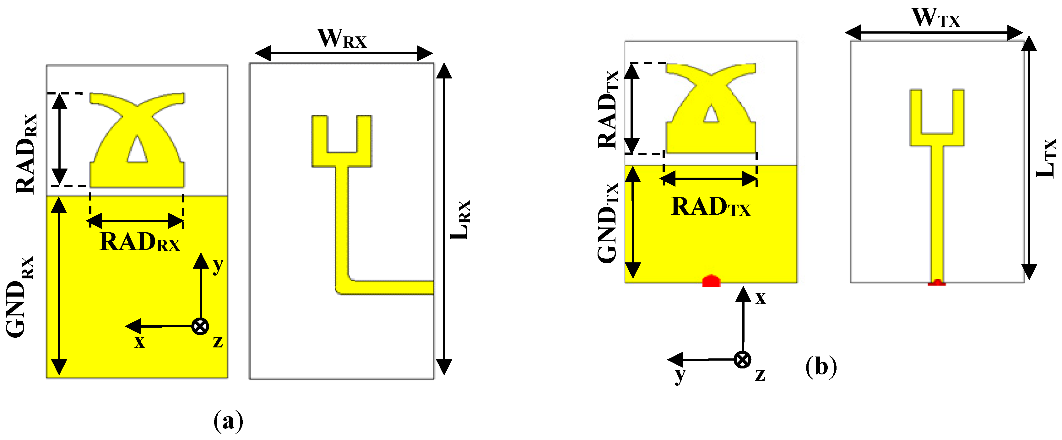
Figure 6.
Numerical results achieved for the RX and the TX tag antennas: (a) comparison between the |S11| of the two monopoles; (b) 3D radiation patterns of the RX tag antenna calculated at 2.1 GHz and 2.4 GHz (b); (c) 3D radiation patterns of the TX antenna calculated at 2.1 GHz and 2.4 GHz.
Figure 6.
Numerical results achieved for the RX and the TX tag antennas: (a) comparison between the |S11| of the two monopoles; (b) 3D radiation patterns of the RX tag antenna calculated at 2.1 GHz and 2.4 GHz (b); (c) 3D radiation patterns of the TX antenna calculated at 2.1 GHz and 2.4 GHz.

Figure 7.
Numerical results achieved for a 2-bit overall system tag: (a) setup used during full-wave simulations; (b) numerical results achieved for the RCS of the device reported in Figure 7a.
Figure 7.
Numerical results achieved for a 2-bit overall system tag: (a) setup used during full-wave simulations; (b) numerical results achieved for the RCS of the device reported in Figure 7a.

Figure 8.
Experimental results achieved for a 2-bit prototype: (a) 2-bit prototype under test; (b) |S21| corresponding to all possible configurations; (c) phase of the S21 corresponding to all the possible configurations.
Figure 8.
Experimental results achieved for a 2-bit prototype: (a) 2-bit prototype under test; (b) |S21| corresponding to all possible configurations; (c) phase of the S21 corresponding to all the possible configurations.
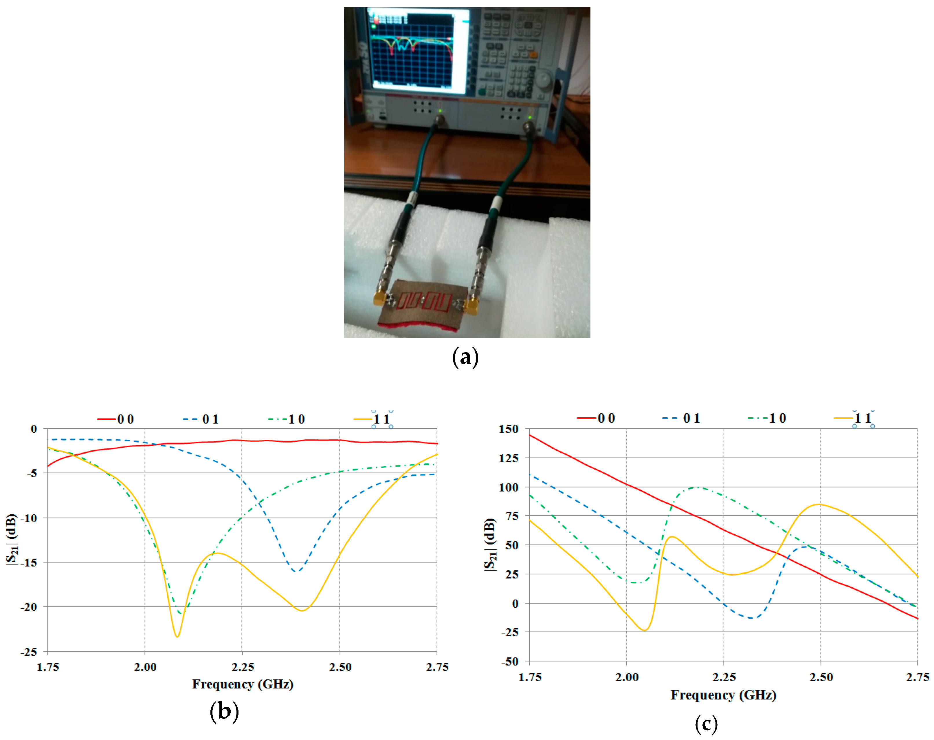
Figure 9.
Experimental results achieved for the TX tag antenna and the RX tag antenna: (a) front view and back view of the RX antenna prototype; (b) front view and back view of the TX antenna prototype; (c) measured reflection coefficients.
Figure 9.
Experimental results achieved for the TX tag antenna and the RX tag antenna: (a) front view and back view of the RX antenna prototype; (b) front view and back view of the TX antenna prototype; (c) measured reflection coefficients.
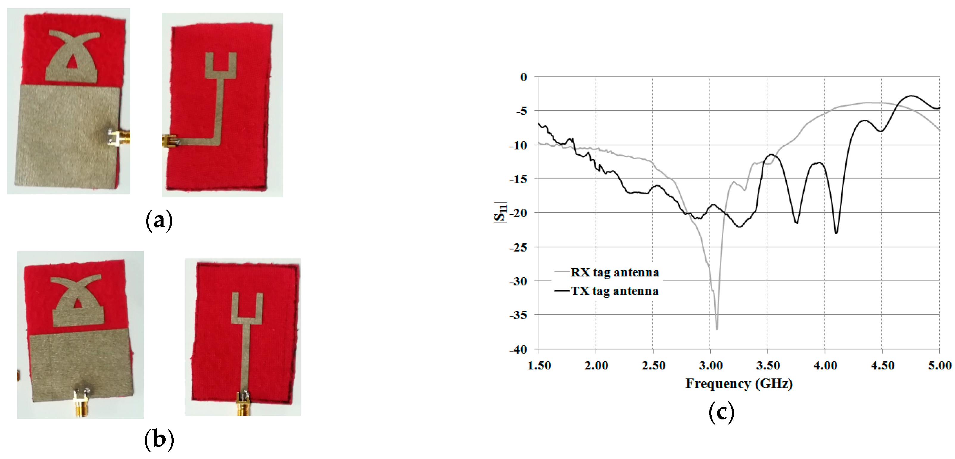
Figure 10.
Experimental results achieved for the 2-bit tag. (a) Front and (b) back view of the stopband microstrip line integrated with the RX antenna; (c) experimental setup adopted for measurements; (d) measured transmission coefficients for the four configurations of interest.
Figure 10.
Experimental results achieved for the 2-bit tag. (a) Front and (b) back view of the stopband microstrip line integrated with the RX antenna; (c) experimental setup adopted for measurements; (d) measured transmission coefficients for the four configurations of interest.

Table 1.
Dimensions of the antennas illustrated in Figure 5.
Table 1.
Dimensions of the antennas illustrated in Figure 5.
| RX antenna | TX antenna | ||||||
|---|---|---|---|---|---|---|---|
| WRX | LRX | GNDRX | RADRX | WTX | LTX | GNDTX | RADTX |
| 50 | 85.9 | 50 | 26 | 50 | 70 | 34.1 | 26 |
All parameters are in millimeters.
Table 2.
Numerical results achieved for the RX and the TX tag antennas.
| BW-10 dB (GHz) | |S11| (dB) | Directivity (dBi) | |||||
|---|---|---|---|---|---|---|---|
| @ 2 GHz | @ 3 GHz | @ 4 GHz | @ 2 GHz | @ 3 GHz | @ 4 GHz | ||
| RX | 1.97–3.93 | –10.1 | –10.9 | –9.14 | 3.40 | 3.99 | 3.44 |
| TX | 1.86–4.2 | –13.3 | –11.03 | –17.9 | 2.75 | 4.06 | 4.17 |
Table 3.
Geometrical parameters of the 2-bit prototype shown in Figure 8a.
Table 3.
Geometrical parameters of the 2-bit prototype shown in Figure 8a.
| 2-bits Prototype | ||||||||
|---|---|---|---|---|---|---|---|---|
| W | L | Wfeed | Wres | Lres | tres | dres | gres | SF2 |
| 40 | 60 | 3.7 | 19.1 | 18.3 | 1.2 | 2 | 4 | 0.77 |
All parameters are in millimeters.
© 2019 by the authors. Licensee MDPI, Basel, Switzerland. This article is an open access article distributed under the terms and conditions of the Creative Commons Attribution (CC BY) license (http://creativecommons.org/licenses/by/4.0/).
Share and Cite
MDPI and ACS Style
Corchia, L.; Monti, G.; Tarricone, L. A Frequency Signature RFID Chipless Tag for Wearable Applications. Sensors 2019, 19, 494. https://doi.org/10.3390/s19030494
AMA Style
Corchia L, Monti G, Tarricone L. A Frequency Signature RFID Chipless Tag for Wearable Applications. Sensors. 2019; 19(3):494. https://doi.org/10.3390/s19030494
Chicago/Turabian StyleCorchia, Laura, Giuseppina Monti, and Luciano Tarricone. 2019. "A Frequency Signature RFID Chipless Tag for Wearable Applications" Sensors 19, no. 3: 494. https://doi.org/10.3390/s19030494
Note that from the first issue of 2016, this journal uses article numbers instead of page numbers. See further details here.