Solving Monocular Visual Odometry Scale Factor with Adaptive Step Length Estimates for Pedestrians Using Handheld Devices

 , , , and
Abstract
:1. Introduction
2. Related Work
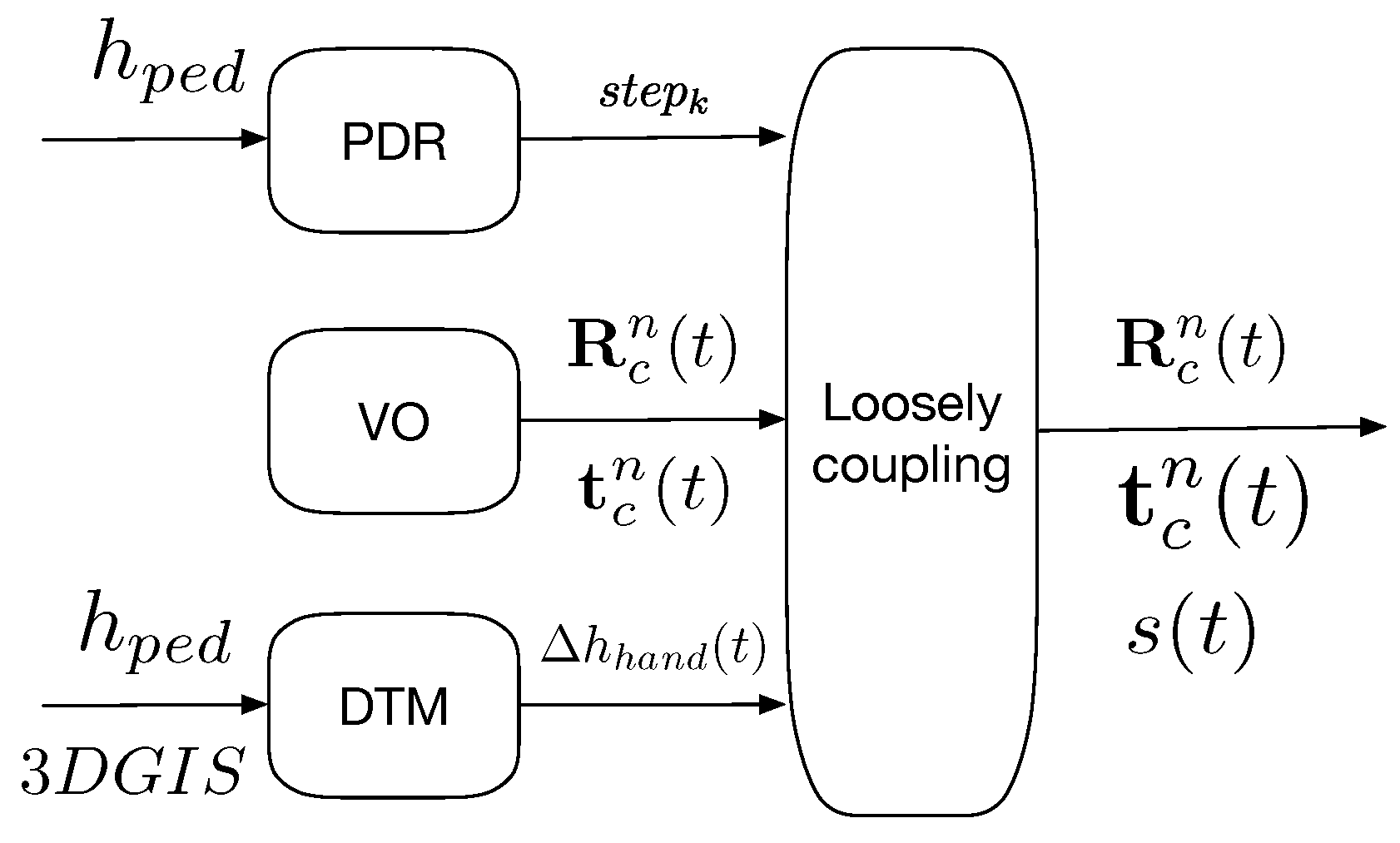
3. Scaled Monocular Visual Odometry
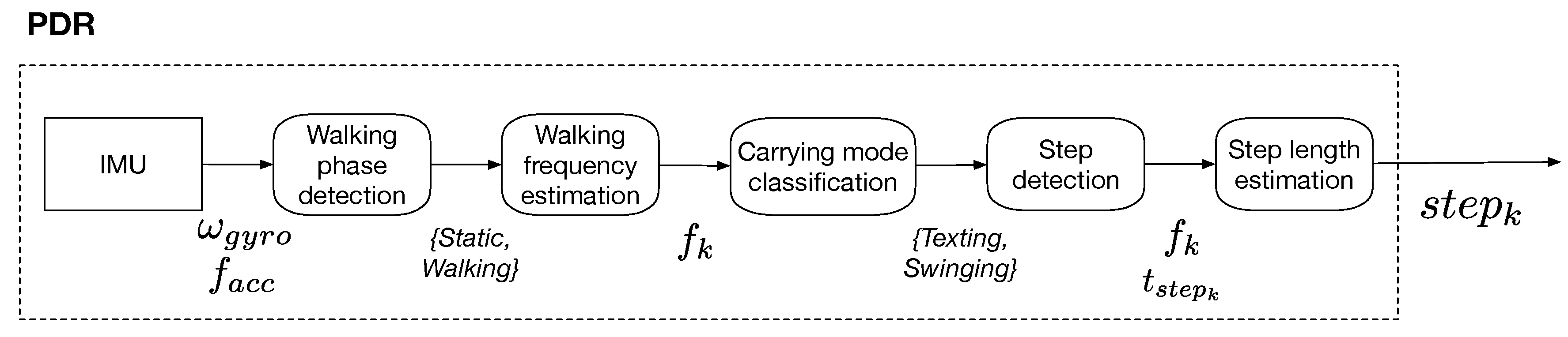
3.1. Step Length Estimation Process
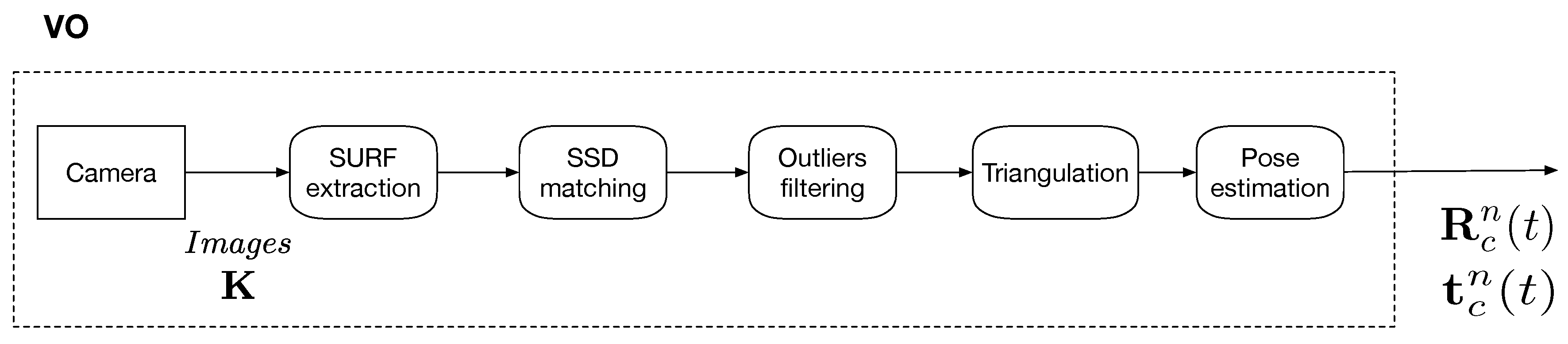
3.2. Monocular Visual Odometry
3.3. Digital Terrain Model and Handheld Height
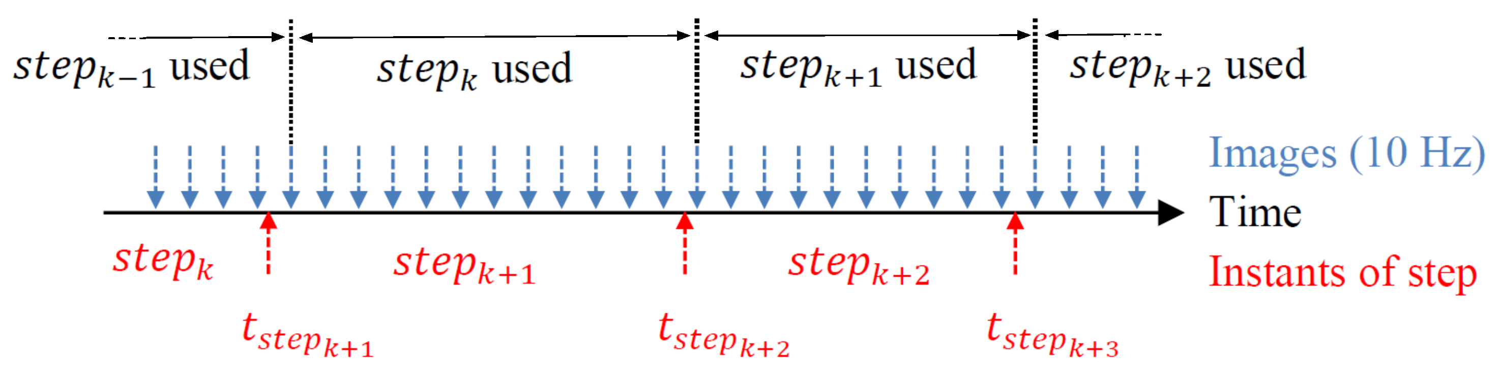
3.4. Scale Determination
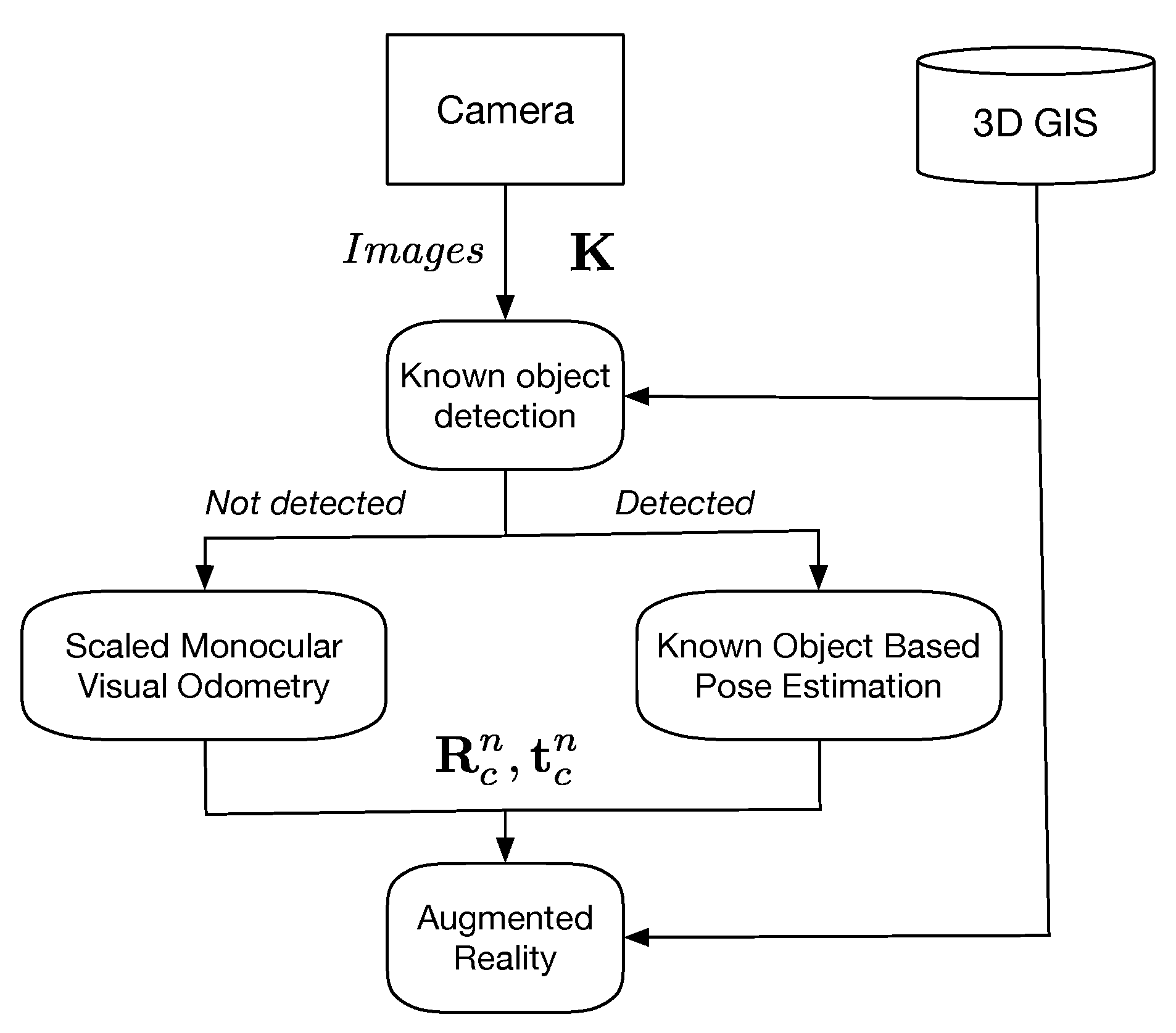
3.5. Known Object Recognition-Based Pose Estimation
- The Known Object Detection;
- The pose estimation;
- (a)
- The Scaled Monocular Visual Odometry (relative pose estimate).
- (b)
- The Known Object-Based Pose Estimation (absolute pose estimate).
- The AR visualization.
4. Experiments
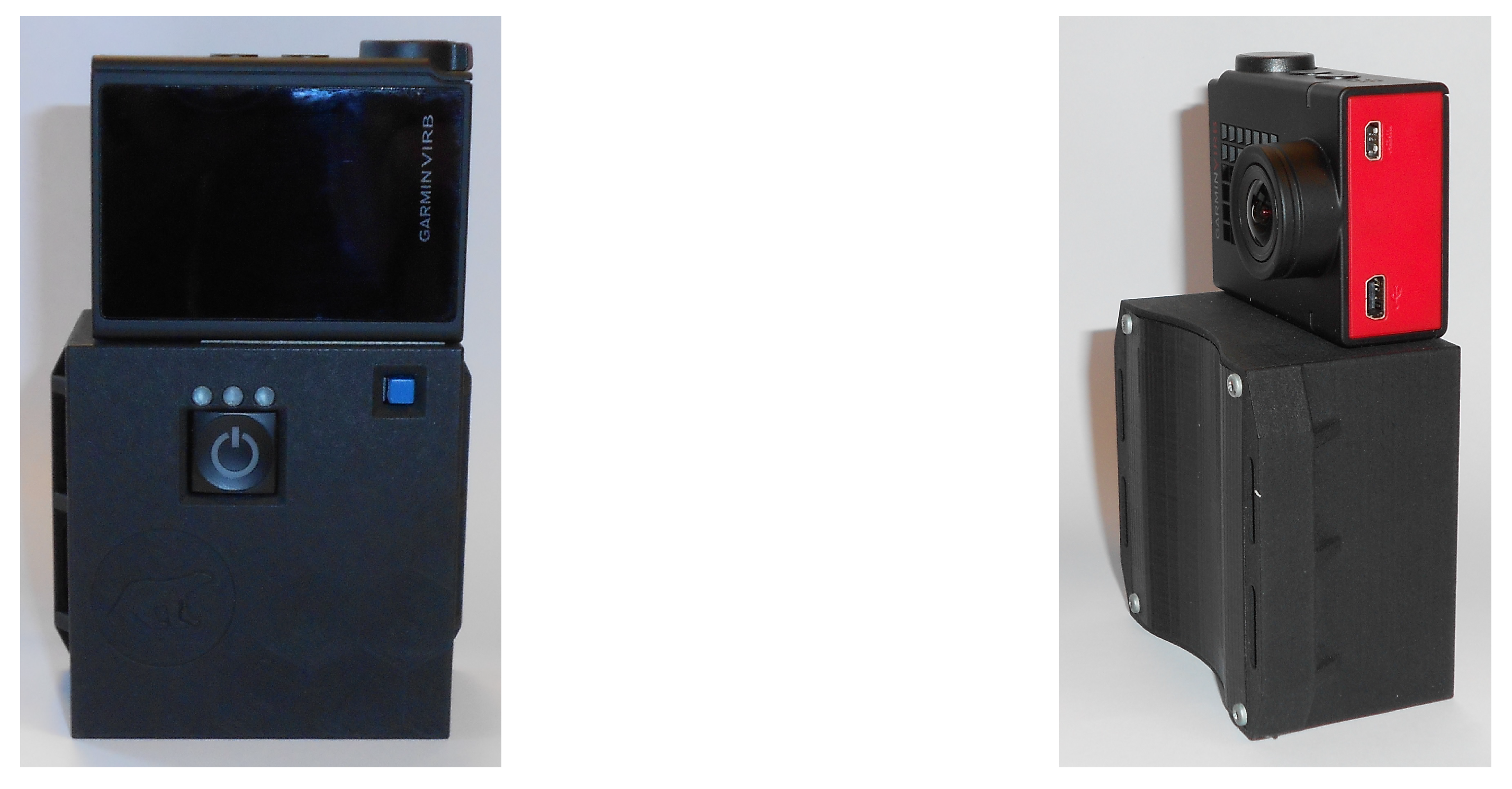
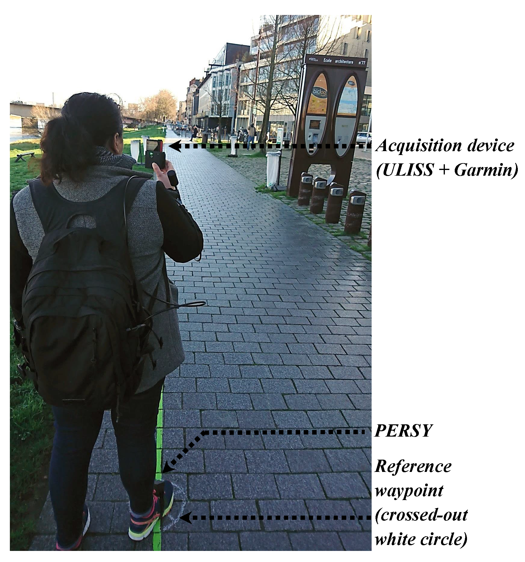
4.1. Hardware Setup
4.2. Digital Terrain Model
4.3. Scenario
4.4. Estimation of Reference Waypoints and Tracks
5. Evaluation
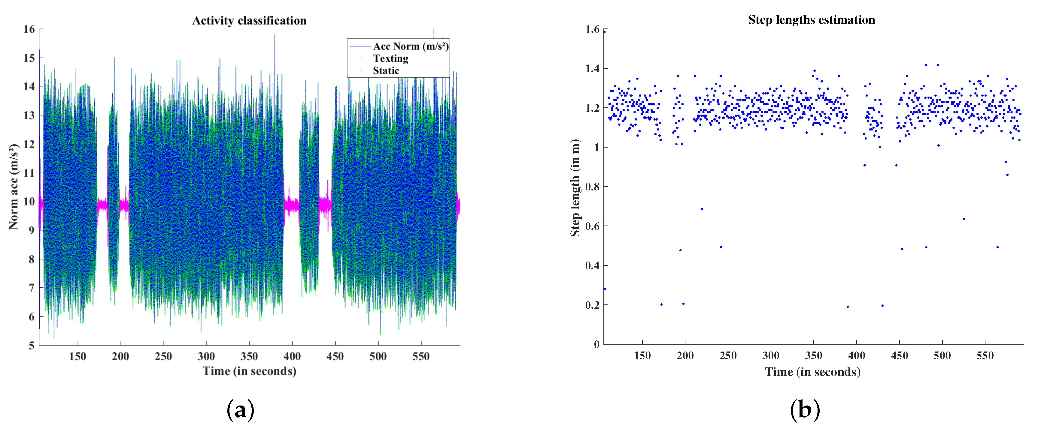
5.1. Activities Classification and Step Length Estimation
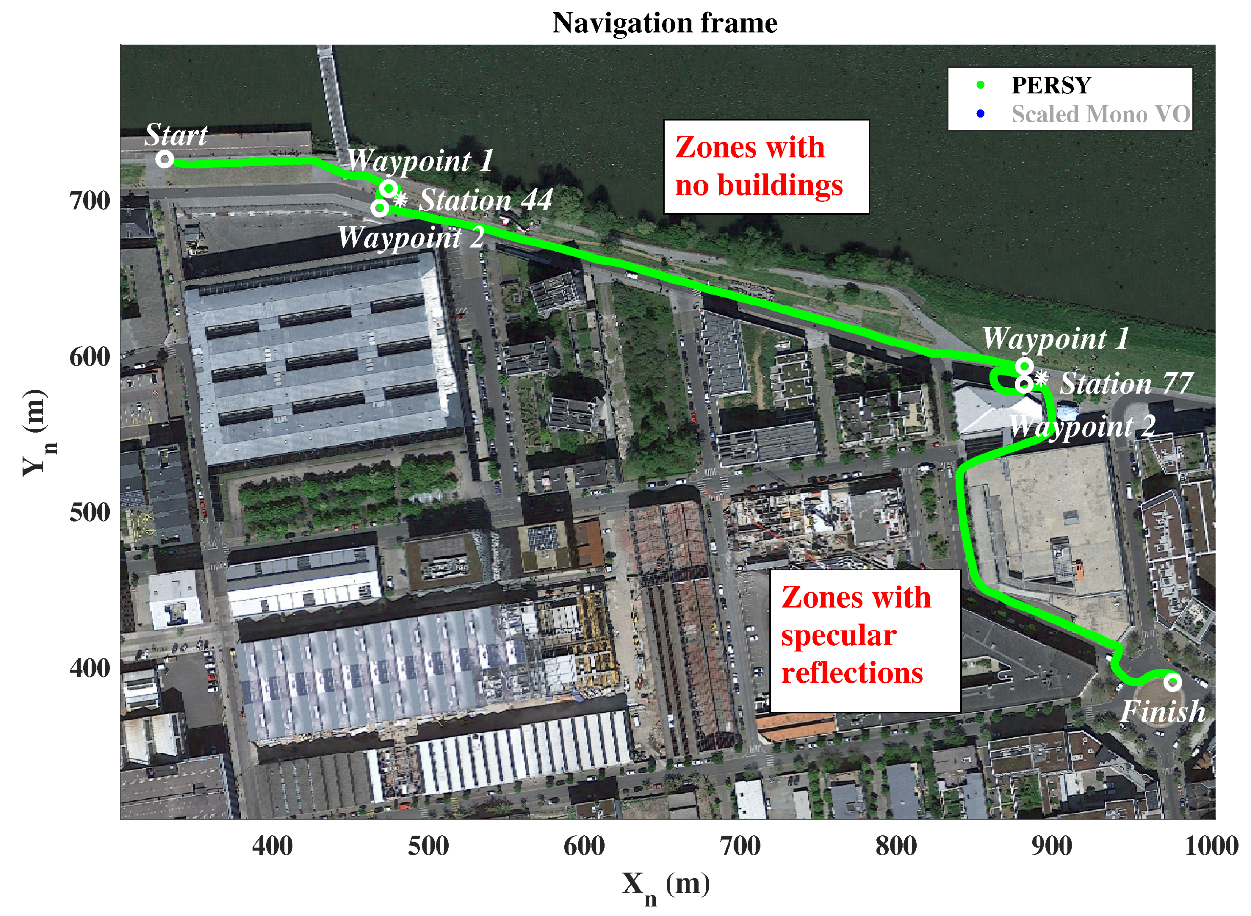
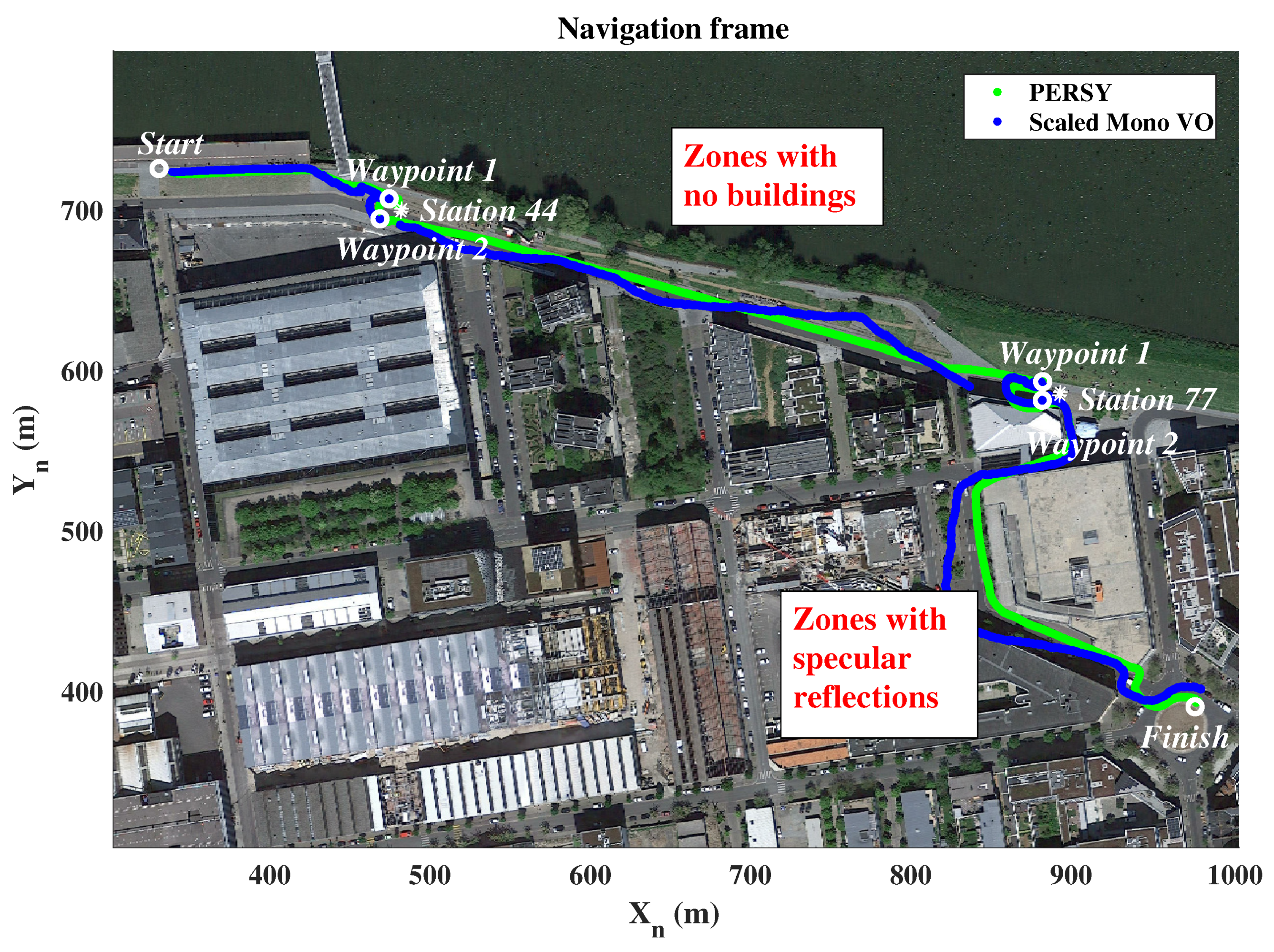
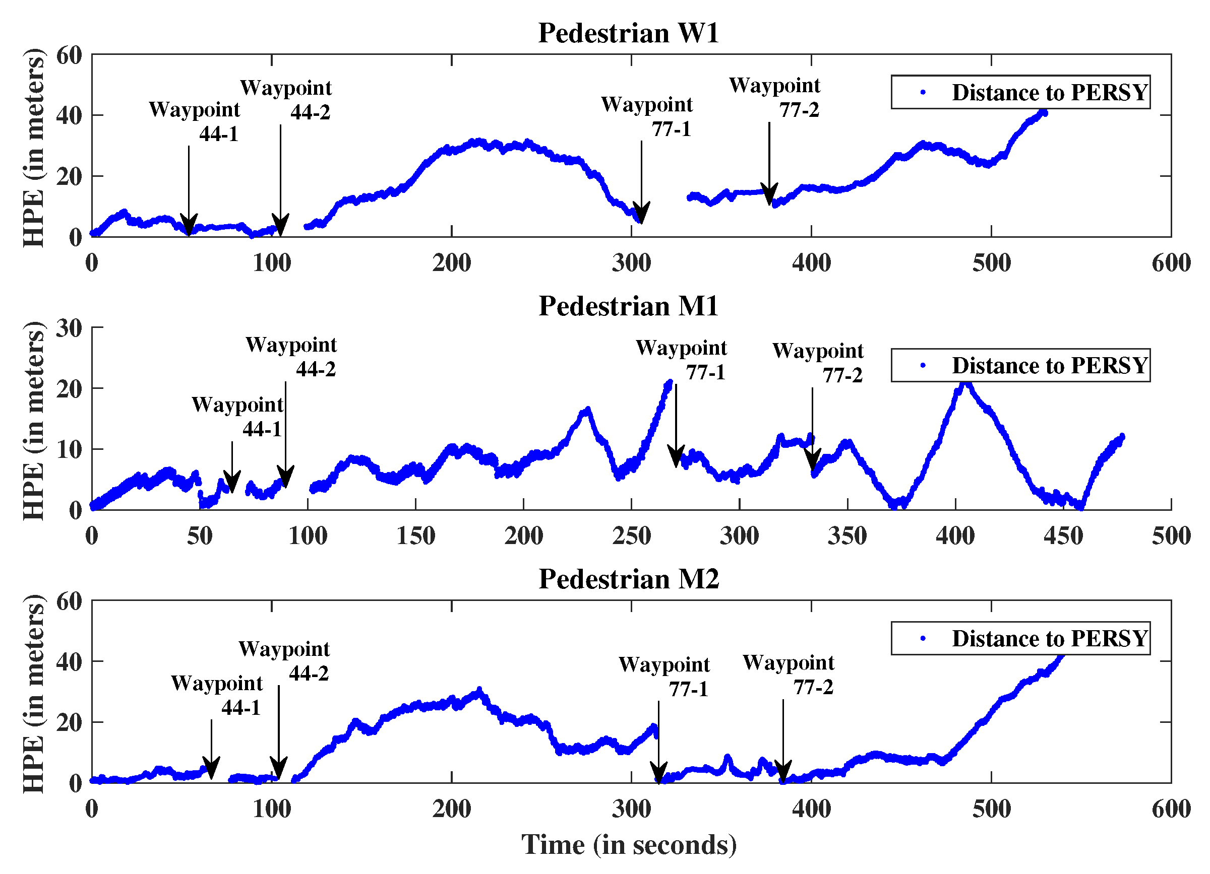
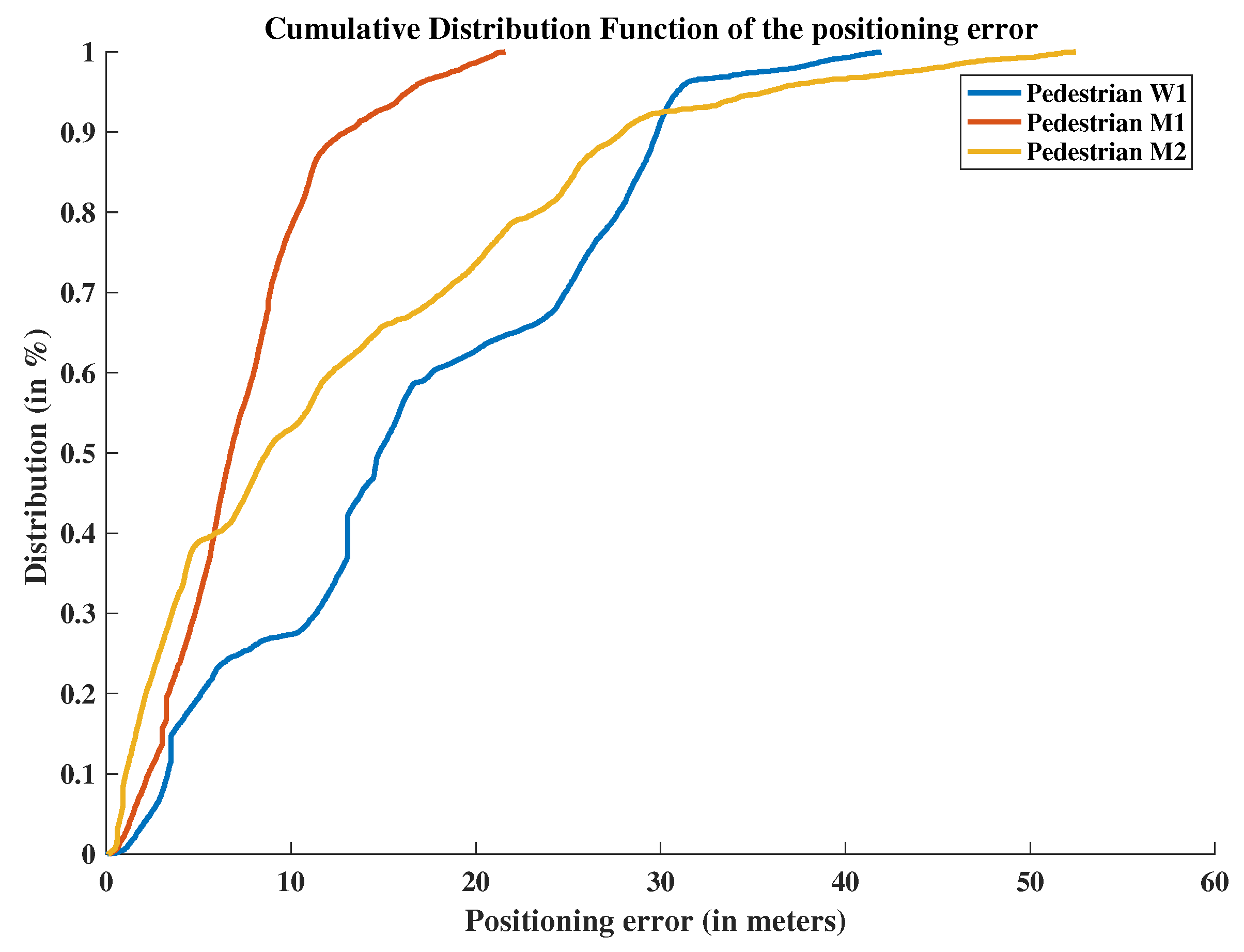
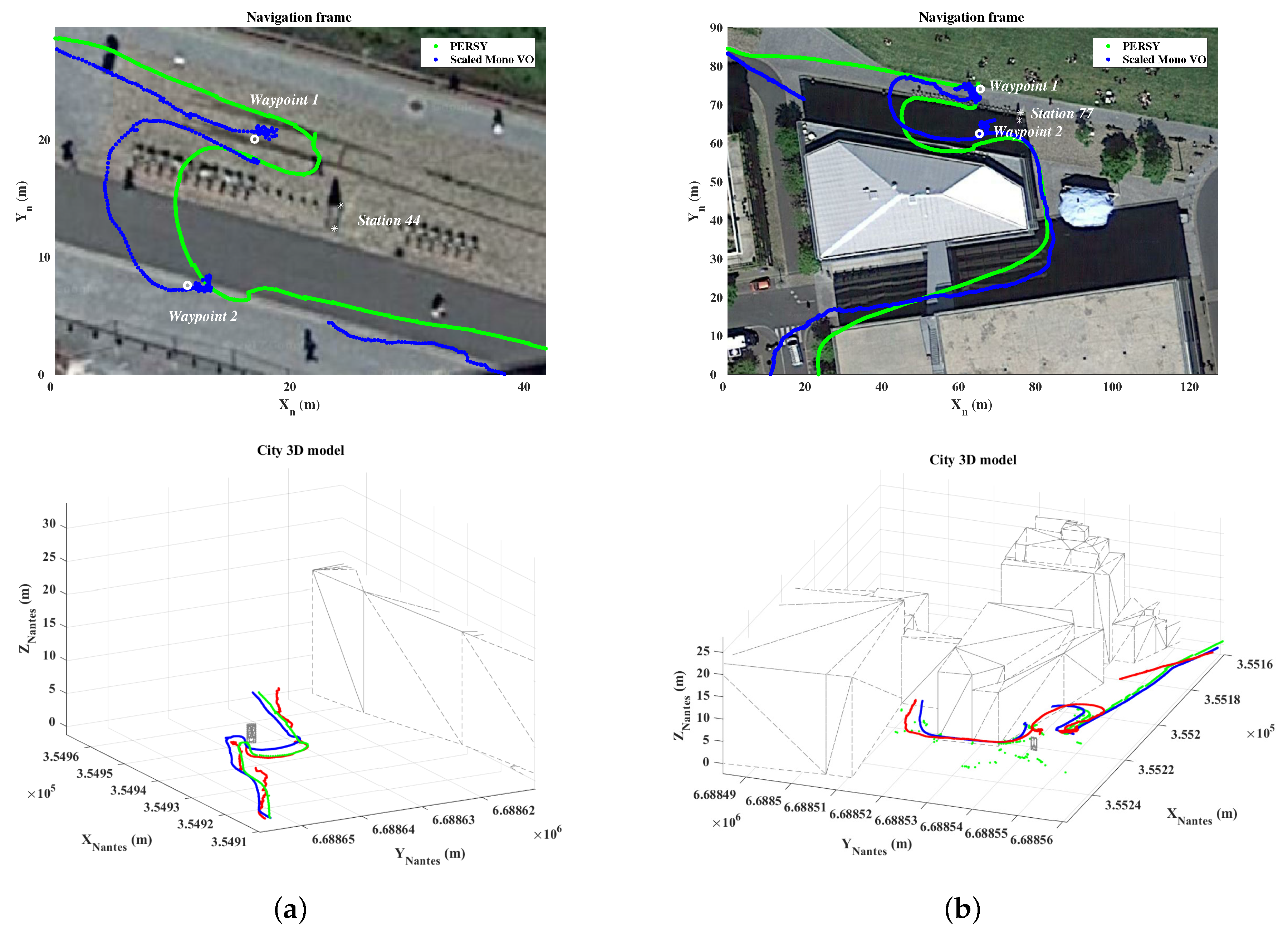
5.2. Estimated Trajectory
6. Conclusions
Author Contributions
Funding
Conflicts of Interest
References
- Schall, G.; Wagner, D.; Reitmayr, G.; Taichmann, E.; Wieser, M.; Schmalstieg, D.; Hofmann-Wellenhof, B. Global pose estimation using multi-sensor fusion for outdoor Augmented Reality. In Proceedings of the 2009 8th IEEE International Symposium on Mixed and Augmented Reality, Orlando, FL, USA, 19–22 October 2009; pp. 153–162. [Google Scholar] [CrossRef]
- Arth, C.; Klopschitz, M.; Reitmayr, G.; Schmalstieg, D. Real-time self-localization from panoramic images on mobile devices. In Proceedings of the 2011 10th IEEE International Symposium on Mixed and Augmented Reality, Basel, Switzerland, 26–29 October 2011; pp. 37–46. [Google Scholar]
- Ventura, J.; Arth, C.; Reitmayr, G.; Schmalstieg, D. Global localization from monocular slam on a mobile phone. IEEE Trans. Visual Comput. Graphics 2014, 20, 531–539. [Google Scholar] [CrossRef] [PubMed]
- Zandbergen, P.A.; Barbeau, S.J. Positional Accuracy of Assisted GPS Data from High-Sensitivity GPS-enabled Mobile Phones. J. Navig. 2011, 64, 381–399. [Google Scholar] [CrossRef]
- Lategahn, H.; Schreiber, M.; Ziegler, J.; Stiller, C. Urban localization with camera and inertial measurement unit. In Proceedings of the 2013 IEEE Intelligent Vehicles Symposium (IV), Gold Coast, Australia, 23–26 June 2013; pp. 719–724. [Google Scholar]
- Yu, L.; Joly, C.; Bresson, G.; Moutarde, F. Improving robustness of monocular urban localization using augmented Street View. In Proceedings of the 2016 IEEE 19th International Conference on Intelligent Transportation Systems (ITSC), Rio de Janeiro, Brazil, 1–4 November 2016; pp. 513–519. [Google Scholar]
- Khan, W.Z.; Xiang, Y.; Aalsalem, M.Y.; Arshad, Q. Mobile Phone Sensing Systems: A Survey. IEEE Commun. Surv. Tutor. 2013, 15, 402–427. [Google Scholar] [CrossRef] [Green Version]
- Davison, A.J.; Reid, I.D.; Molton, N.D.; Stasse, O. MonoSLAM: Real-time single camera SLAM. IEEE Trans. Pattern Anal. Mach. Intell. 2007, 29, 1052–1067. [Google Scholar] [CrossRef] [PubMed]
- Engel, J.; Schöps, T.; Cremers, D. LSD-SLAM: Large-scale direct monocular SLAM. In Lecture Notes in Computer Science; Springer: Cham, Switzerland, 2014; pp. 834–849. [Google Scholar]
- Mur-Artal, R.; Tardós, J.D. ORB-SLAM2: An Open-Source SLAM System for Monocular, Stereo and RGB-D Cameras. IEEE Trans. Rob. 2017, 33, 1255–1262. [Google Scholar] [CrossRef]
- Cummins, M.; Newman, P. Appearance-only SLAM at large scale with FAB-MAP 2.0. Int. J. Rob. Res. 2011, 30, 1100–1123. [Google Scholar] [CrossRef]
- Lynen, S.; Sattler, T.; Bosse, M.; Hesch, J.; Pollefeys, M.; Siegwart, R. Get Out of My Lab: Large-scale, Real-Time Visual-Inertial Localization. In Proceedings of the Robotics: Science and Systems XI, Rome, Italy, 13–17 July 2015. [Google Scholar] [CrossRef]
- Jimenez, A.R.; Seco, F.; Prieto, C.; Guevara, J. A comparison of pedestrian dead-reckoning algorithms using a low-cost MEMS IMU. In Proceedings of the 2009 IEEE International Symposium on Intelligent Signal Processing, Budapest, Hungary, 26–28 August 2009; pp. 37–42. [Google Scholar]
- Fischer, C.; Sukumar, P.T.; Hazas, M. Tutorial: Implementing a pedestrian tracker using inertial sensors. IEEE Pervasive Comput. 2013, 12, 17–27. [Google Scholar] [CrossRef]
- Jiang, B.; Neumann, U.; You, S. A robust hybrid tracking system for outdoor augmented reality. In Proceedings of the IEEE Virtual Reality 2004, Chicago, IL, USA, 27–31 March 2004; pp. 3–11. [Google Scholar] [CrossRef]
- Beich, M.J.; Veth, C.M. Tightly coupled image-aided inertial relative navigation using Statistical Predictive Rendering (SPR) techniques and a priori world Models. In Proceedings of the IEEE/ION Position, Location and Navigation Symposium, Indian Wells, CA, USA, 4–6 May 2010; pp. 552–560. [Google Scholar] [CrossRef]
- Oskiper, T.; Samarasekera, S.; Kumar, R. Tightly coupled robust vision aided inertial navigation algorithm for augmented reality using monocular camera and IMU. In Proceedings of the 2011 10th IEEE International Symposium on Mixed and Augmented Reality, Basel, Switzerland, 26–29 October 2011. [Google Scholar] [CrossRef]
- Oskiper, T.; Samarasekera, S.; Kumar, R. [POSTER] CamSLAM: Vision Aided Inertial Tracking and Mapping Framework for Large Scale AR Applications. In Proceedings of the 2017 IEEE International Symposium on Mixed and Augmented Reality (ISMAR-Adjunct), Nantes, France, 9–13 October 2017; pp. 216–217. [Google Scholar] [CrossRef]
- You, S.; Neumann, U.; Azuma, R. Orientation tracking for outdoor augmented reality registration. IEEE Comput. Graph. Appl. 1999, 19, 36–42. [Google Scholar] [CrossRef]
- Satoh, K.; Anabuki, M.; Yamamoto, H.; Tamura, H. A hybrid registration method for outdoor augmented reality. In Proceedings of the IEEE and ACM International Symposium on Augmented Reality, New York, NY, USA, 29–30 October 2001; pp. 67–76. [Google Scholar] [CrossRef]
- Nistér, D.; Naroditsky, O.; Bergen, J. Visual odometry. In Proceedings of the 2004 IEEE Computer Society Conference on Computer Vision and Pattern Recognition, Washington, DC, USA, 27 June–2 July 2004. [Google Scholar]
- Scaramuzza, D.; Fraundorfer, F. Visual odometry [tutorial]. IEEE Rob. Autom Mag. 2011, 18, 80–92. [Google Scholar] [CrossRef]
- Aqel, M.O.A.; Marhaban, M.H.; Saripan, M.I.; Ismail, N. Review of visual odometry: Types, approaches, challenges, and applications. In SpringerPlus; Springer: Cham, Switzerland, 2016. [Google Scholar]
- Klein, G.; Murray, D. Parallel tracking and mapping for small AR workspaces. In Proceedings of the 2007 6th IEEE and ACM International Symposium on Mixed and Augmented Reality, Nara, Japan, 13–16 November 2007; pp. 225–234. [Google Scholar] [CrossRef]
- Strasdat, H.; Montiel, J.; Davison, A.J. Scale drift-aware large scale monocular SLAM. In Robotics: Science and Systems VI; MIT Press: Cambridge, MA, USA, 2010. [Google Scholar]
- Wang, R.; Schwörer, M.; Cremers, D. Stereo DSO: Large-scale direct sparse visual odometry with stereo cameras. In Proceedings of the International Conference on Computer Vision (ICCV), Venice, Italy, 22–29 October 2017. [Google Scholar]
- Botterill, T.; Mills, S.; Green, R. Correcting Scale Drift by Object Recognition in Single-Camera SLAM. IEEE Trans. Cybern. 2013, 43, 1767–1780. [Google Scholar] [CrossRef] [PubMed]
- Lothe, P.; Bourgeois, S.; Royer, E.; Dhome, M.; Naudet-Collette, S. Real-time vehicle global localisation with a single camera in dense urban areas: Exploitation of coarse 3D city models. In Proceedings of the 2010 IEEE Computer Society Conference on Computer Vision and Pattern Recognition, San Francisco, CA, USA, 13–18 June 2010; pp. 863–870. [Google Scholar] [CrossRef]
- Gakne, P.V.; O’Keefe, K. Tackling the Scale Factor Issue in A Monocular Visual Odometry Using A 3D City Model. In Proceedings of the ITSNT 2018, International Technical Symposium on Navigation and Timing, Toulouse, France, 13–16 November 2018. [Google Scholar] [CrossRef]
- Weiss, S.; Siegwart, R. Real-time metric state estimation for modular vision-inertial systems. In Proceedings of the 2011 IEEE International Conference on Robotics and Automation, Shanghai, China, 9–13 May 2011; pp. 4531–4537. [Google Scholar]
- Nützi, G.; Weiss, S.; Scaramuzza, D.; Siegwart, R. Fusion of IMU and vision for absolute scale estimation in monocular SLAM. J. Intell. Rob. Syst. 2011, 61, 287–299. [Google Scholar] [CrossRef]
- Knorr, S.B.; Kurz, D. Leveraging the User’s Face for Absolute Scale Estimation in Handheld Monocular SLAM. In Proceedings of the 2016 IEEE International Symposium on Mixed and Augmented Reality (ISMAR), Merida, Mexico, 19–23 September 2016; pp. 11–17. [Google Scholar]
- Lupton, T.; Sukkarieh, S. Removing scale biases and ambiguity from 6DoF monocular SLAM using inertial. In Proceedings of the 2008 IEEE International Conference on Robotics and Automation, Pasadena, CA, USA, 19–23 May 2008; pp. 3698–3703. [Google Scholar] [CrossRef]
- Gutiérrez-Gómez, D.; Guerrero, J.J. Scaled monocular SLAM for walking people. In Proceedings of the 2013 International Symposium on Wearable Computers, Zurich, Switzerland, 8–12 September 2013; pp. 9–12. [Google Scholar]
- Leppäkoski, H.; Collin, J.; Takala, J. Pedestrian navigation based on inertial sensors, indoor map, and WLAN signals. In Proceedings of the 2012 IEEE International Conference on Acoustics, Speech and Signal Processing (ICASSP), Kyoto, Japan, 25–30 March 2012; pp. 1569–1572. [Google Scholar] [CrossRef]
- Tomazic, S.; Skrjanc, I. Fusion of visual odometry and inertial navigation system on a smartphone. Comput. Ind. 2015, 74, 119–134. [Google Scholar] [CrossRef]
- Renaudin, V.; Susi, M.; Lachapelle, G. Step Length Estimation Using Handheld Inertial Sensors. Sensors 2012, 12, 8507–8525. [Google Scholar] [CrossRef] [PubMed] [Green Version]
- Susi, M.; Renaudin, V.; Lachapelle, G. Motion Mode Recognition and Step Detection Algorithms for Mobile Phone Users. Sensors 2013, 13, 1539–1562. [Google Scholar] [CrossRef] [PubMed] [Green Version]
- Taketomi, T.; Uchiyama, H.; Ikeda, S. Visual SLAM algorithms: A survey from 2010 to 2016. IPSJ Trans. Comput. Vis. Appl. 2017, 9, 16. [Google Scholar] [CrossRef]
- Bouguet, J.Y. Camera Calibration Toolbox for Matlab. 2008. Available online: http://www.vision.caltech.edu/bouguetj/calib_doc/ (accessed on 22 February 2019).
- Hartley, R.; Zisserman, A. Multiple View Geometry in Computer Vision; Cambridge University Press: Cambridge, UK, 2003. [Google Scholar]
- Zhang, Z. A flexible new technique for camera calibration. IEEE Trans. Pattern Anal. Mach. Intell. 2000, 22, 1330–1334. [Google Scholar] [CrossRef] [Green Version]
- Bay, H.; Ess, A.; Tuytelaars, T.; Gool, L.V. Speeded-Up Robust Features (SURF). Comput. Vis. Image Underst. 2008, 110, 346–359. [Google Scholar] [CrossRef] [Green Version]
- Torr, P.; Zisserman, A. MLESAC. Comput. Vis. Image Underst. 2000, 78, 138–156. [Google Scholar] [CrossRef]
- Wu, Y. Image Based Camera Localization: An Overview. arXiv, 2016; arXiv:1610.03660. [Google Scholar] [CrossRef]
- Cai, J.; Miklavcic, S. The generation of digital terrain models from LiDAR data using seeding and filtering and its application to flood modelling. In Proceedings of the 2011 International Conference on Multimedia Technology, Hangzhou, China, 26–28 July 2011; pp. 5622–5625. [Google Scholar] [CrossRef]
- Antigny, N.; Servières, M.; Renaudin, V. Fusion of 3D GIS, Vision, Inertial and Magnetic Data for Improved Urban Pedestrian Navigation and Augmented Reality Applications. Navigation 2018, 65, 431–447. [Google Scholar] [CrossRef]
- Ortiz, M.; De Sousa, M.; Renaudin, V. A New PDR Navigation Device for Challenging Urban Environments. J. Sens. 2017, 2017, 4080479. [Google Scholar] [CrossRef]
- Signorelli, V.; Leduc, T. Utilisation du Socle 3D CityGML Nantes-Secteur Centre-Ville; Technical Report; UMR CNRS 1563 AAU/CRENAU: Nantes, France, 2015. [Google Scholar]
- Scornec, J.L.; Ortiz, M.; Renaudin, V. Foot-mounted pedestrian navigation reference with tightly coupled GNSS carrier phases, inertial and magnetic data. In Proceedings of the 2017 International Conference on Indoor Positioning and Indoor Navigation (IPIN), Sapporo, Japan, 18–21 September 2017; pp. 1–8. [Google Scholar] [CrossRef]
- Renaudin, V.; Combettes, C. Magnetic, Acceleration Fields and Gyroscope Quaternion (MAGYQ)-Based Attitude Estimation with Smartphone Sensors for Indoor Pedestrian Navigation. Sensors 2014, 14, 22864–22890. [Google Scholar] [CrossRef] [PubMed] [Green Version]
- Antigny, N.; Servieres, M.; Renaudin, V. Pedestrian Track Estimation with Handheld Monocular Camera and Inertial-Magnetic Sensor for Urban Augmented Reality. In Proceedings of the 2017 International Conference on Indoor Positioning and Indoor Navigation (IPIN), Sapporo, Japan, 18–21 September 2017. [Google Scholar]
- Engel, J.; Sturm, J.; Cremers, D. Semi-dense visual odometry for a monocular camera. In Proceedings of the 2013 IEEE International Conference on Computer Vision (ICCV), Sydney, Australia, 1–8 December 2013; pp. 1449–1456. [Google Scholar]


| Pedestrians | M1 | M2 | W1 | W2 | W3 |
|---|---|---|---|---|---|
| Gender | Male | Male | Female | Female | Female |
| 1.87 m | 1.80 m | 1.69 m | 1.69 m | 1.60 m | |
| 1.67 m | 1.60 m | 1.55 m | 1.50 m | 1.40 m | |
| 0.20 m | 0.20 m | 0.14 m | 0.19 m | 0.20 m | |
| 89% | 88% | 91% | 88% | 87% |
| Pedestrians | W1 | M1 | W2 |
|---|---|---|---|
| Gender | Female | Male | Male |
| 1.69 m | 1.87 m | 1.80 m | |
| Acquisition duration | 550 s | 486 s | 574 s |
| Pedestrians | W1 | M1 | W2 |
|---|---|---|---|
| Differential GNSS positioning availability | 90.7 % | 94.5 % | 81.2 % |
| Standalone GPS positioning availability | 86.3 % | 78.9 % | 54.8 % |
| Pedestrians | W1 | M1 | W2 |
|---|---|---|---|
| Median step length | 1.06 m | 1.18 m | 0.99 m |
| Step lengths standard deviation | 0.20 m | 0.14 m | 0.29 m |
| Pedestrians | W1 | M1 | W2 |
|---|---|---|---|
| On waypoint 44-1 (after 120 m) | 2.84 m | 27.97 m | 3.58 m | 13.17 m | 4.46 m | 35.16 m |
| (2.3% | 23.3%) | (2.9% | 10.9%) | (3.7% | 29.3%) | |
| On waypoint 77-1 (after 550 m) | 6.60 m | 101.06 m | 21.10 m | 78.74 m | 15.11 m | 167.7 m |
| (1.2% | 18.3%) | (3.8% | 14.3%) | (2.7% | 30.5%) | |
| On finish (after 700 m) | 22.43 m | 54.96 m | 11.77 m | 49.80 m | 52.56 m | 89.19 m |
| (3.2% | 7.8%) | (1.6% | 7.1%) | (7.5% | 12.7%) | |
| Mean positioning error | 16.59 m | 26.58 m | 7.33 m | 20.59 m | 12.58 m | 45.09 m |
© 2019 by the authors. Licensee MDPI, Basel, Switzerland. This article is an open access article distributed under the terms and conditions of the Creative Commons Attribution (CC BY) license (http://creativecommons.org/licenses/by/4.0/).
Share and Cite
Antigny, N.; Uchiyama, H.; Servières, M.; Renaudin, V.; Thomas, D.; Taniguchi, R.-i. Solving Monocular Visual Odometry Scale Factor with Adaptive Step Length Estimates for Pedestrians Using Handheld Devices. Sensors 2019, 19, 953. https://doi.org/10.3390/s19040953
Antigny N, Uchiyama H, Servières M, Renaudin V, Thomas D, Taniguchi R-i. Solving Monocular Visual Odometry Scale Factor with Adaptive Step Length Estimates for Pedestrians Using Handheld Devices. Sensors. 2019; 19(4):953. https://doi.org/10.3390/s19040953
Chicago/Turabian StyleAntigny, Nicolas, Hideaki Uchiyama, Myriam Servières, Valérie Renaudin, Diego Thomas, and Rin-ichiro Taniguchi. 2019. "Solving Monocular Visual Odometry Scale Factor with Adaptive Step Length Estimates for Pedestrians Using Handheld Devices" Sensors 19, no. 4: 953. https://doi.org/10.3390/s19040953