The Sensor Web: A Macro-Instrument for Coordinated Sensing

Jet Propulsion Laboratory, California Institute of Technology, Pasadena, CA 91109-8099, USA
Sensors 2002, 2(7), 270-285; https://doi.org/10.3390/s20700270
Submission received: 9 July 2002
/
Accepted: 14 July 2002
/
Published: 14 July 2002
(This article belongs to the Special Issue Networked Sensors and Wireless Sensor Platforms)
Abstract
:The Sensor Web is a macro-instrument concept that allows for the spatio-temporal understanding of an environment through coordinated efforts between multiple numbers and types of sensing platforms, including both orbital and terrestrial and both fixed and mobile. Each of these platforms, or pods, communicates within their local neighborhood and thus distributes information to the instrument as a whole. Much as intelligence in the brain is a result of the myriad of connections between dendrites, it is anticipated that the Sensor Web will develop a macro-intelligence as a result of its distributed information with the pods reacting and adapting to their environment in a way that is much more than their individual sum. The sharing of data among individual pods will allow for a global perception and purpose of the instrument as a whole. The Sensor Web is to sensors what the Internet is to computers, with different platforms and operating systems communicating via a set of shared, robust protocols. This paper will outline the potential of the Sensor Web concept and describe the Jet Propulsion Laboratory (JPL) Sensor Webs Project (http://sensorwebs.jpl.nasa.gov/). In particular, various fielded Sensor Webs will be discussed.
Key words:
Sensor web; Distributed; Network; Smart sensors; WirelessIntroduction
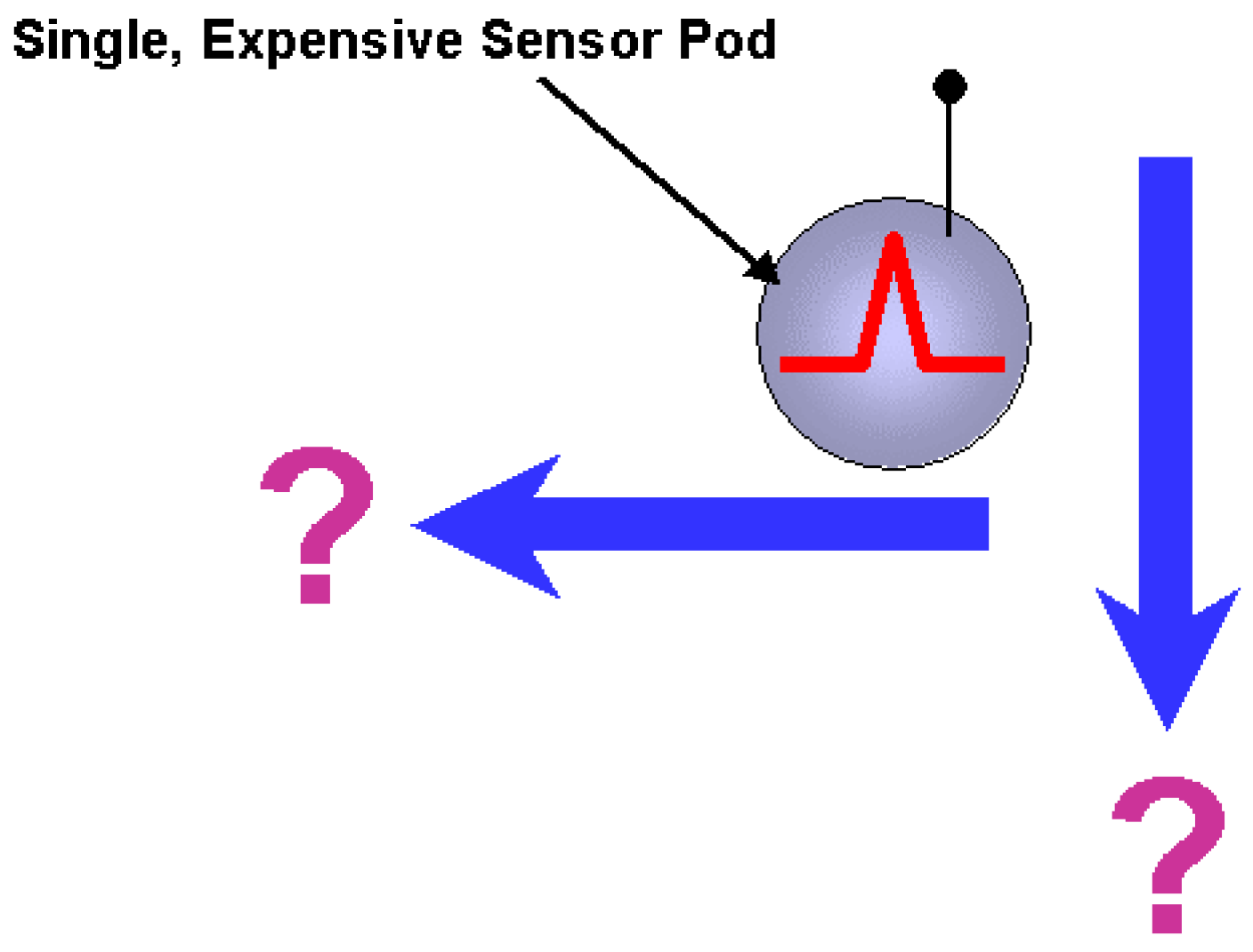
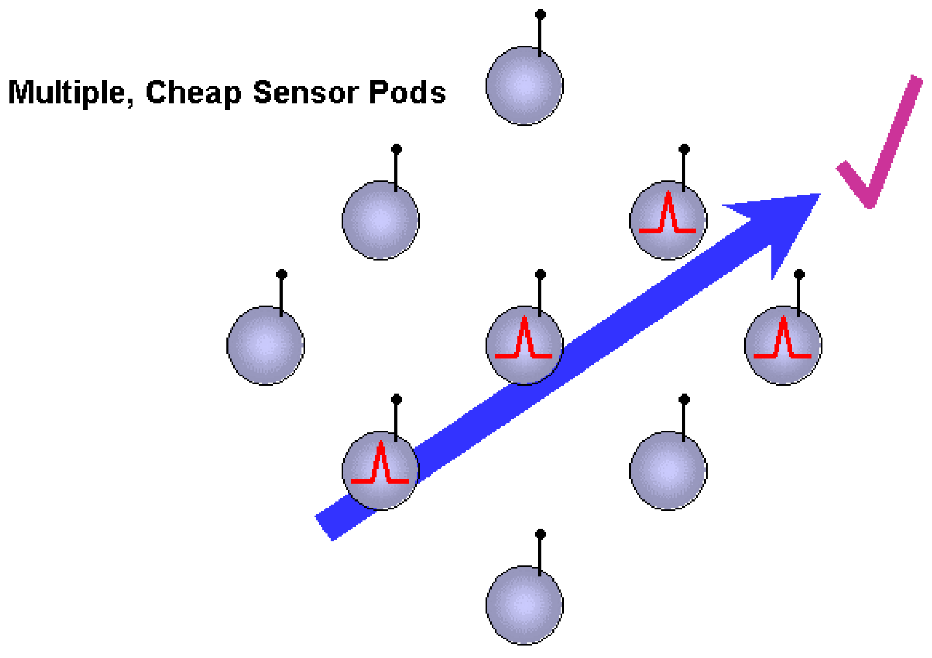
Typical sensor use involves placing a single transducer in an environment to monitor and record a particular aspect of it, as shown schematically in Figure 1. While the resolution of the phenomena may be spectacular, there is little information regarding the general nature of the dynamics associated with the phenomena, save that it took place at a specific place and at a specific time. Moreover, there is no way for the sensor to anticipate its environment. Consider instead the arrangement of sensors shown in Figure 2. Here, cheaper sensors are used with a presumed reduction in measurement fidelity. Nevertheless, by correlating these measurements over space and time, it now becomes possible to extract spatio-temporal dynamics associated with a phenomenon. As a result, these cheaper sensors, correctly configured, can provide a different type of information altogether. This is the essence of a Sensor Web.
Figure 1.
A single sensor does not give any information about spatio-temporal dynamics.

Figure 2.
Multiple sensors provide lower resolution but more data and thus can yield sophisticated results.
Figure 2.
Multiple sensors provide lower resolution but more data and thus can yield sophisticated results.

Sensor Webs are made practical by the present revolutions in computation and telecommunication hardware. The requirements for today’s computers and cellular telephones are so complex that the only possible way to develop these technologies at all is to sell them to a mass market and rely on the economy of scale to provide the necessary financial capital for the next round of development. As a result, mass-produced, commercially available components often represent the state-of-the-art. This is in marked contrast to previous times where the state-of-the-art was represented almost exclusively in government, military, or university laboratories. Today, for example, hardware is so inexpensive that telephone companies will deeply discount, or even give away, cellular phones in anticipation of recouping the costs via telephone service.
The Sensor Web is therefore a new type of instrument that exploits the availability of this low-cost, but extremely advanced, hardware. Additionally, because of its ability to discern spatio-temporal phenomena, the Sensor Web provides a new way to think about environmental monitoring and creating a virtual presence. The Sensor Web is a new instrument concept, capable of being developed for a wide range of applications. This paper will first describe what a Sensor Web is and how it is distinct from seemingly similar constructions such as spatially distributed sensors. A brief discussion of Sensor Web design will follow. Finally, Sensor Webs developed at the Jet Propulsion Laboratory (JPL) and their deployments will be described.
Sensor Web Basics
Definitions
As defined in the NASA New Technology Report on Sensor Webs [1], the Sensor Web consists of a system of intra-communicating, spatially distributed sensor pods that can be deployed to monitor and explore new environments. Typically, the communication occurs wirelessly. Each pod consists of two modules. The first module comprises the transducers that physically interact with the environment and convert environmental parameters into electrical signals. The second module represents the infrastructure of the Sensor Web itself. Included in this module are telecommunication capabilities, power sources and energy harvesting devices, and computation devices to run the protocol schemes and provide for local data analysis. The penultimate goal of a Sensor Web is to extract knowledge from the data collected and adapt and react accordingly.
Although the computation hardware in a pod can be quite sophisticated, it is the sharing of information among the pods that gives the Sensor Web a macro-intelligence. Intelligence in the human brain is created because of a complex, inhomogeneous network of neurons [2] and not because of individual intelligence from each neuron. Similarly, the Sensor Web is an instrument where greater functionality is derived from a parallel-type architecture as sensor measurements (including pod location) are passed, and collectively interpreted, from pod to pod. This global sharing of information will lead to pod synergism (the whole of their activity being greater than the sum of their parts) by permitting intelligent resource (power, bandwidth, consumables) management by the web, and allowing for self-modifying behavior based on environmental factors and internal web diagnostics.
Strictly speaking, the Sensor Web as defined is not limited to terrestrial platforms. In fact, any armada of satellites, autonomous vehicles, and the like may be viewed as a Sensor Web so long as their activities are coordinated by their shared local knowledge of the environment. For example, NASA has occasionally referred to a group of orbiting satellites as a “sensor web” [3]. Although this system could be a type of Sensor Web, it is only a subset of the general concept. The connotation of the term “Sensor Web” has a much broader scope and extends from ultra-large-scale in situ instruments to correlated remote measurements (such as local spectroscopy) to the coordinated flying (swarming) of distributed spacecraft and everything in between. It is thus too restrictive to say that the Sensor Web concept is a design for a cluster of satellites or an in situ instrument, since it can be either one.
As a result, the Sensor Web concept is not a “one-size-fits-all” solution any more than one would expect all satellites to be the same. For example, pod-to-pod baud rates can vary from very low (sonar applications) to the very high (satellite applications). Data transmission schemes in covert military environments are quite different from those on the surface of Mars where there are no FCC regulations. The Sensor Web concept simply allows for information synthesis over a large spatial area and tracking of dynamic phenomena over multiple length scales simultaneously. The unifying feature of all Sensor Webs, therefore, is that the information gathered by the instrument is also used by the instrument, perhaps even modifying its own behavior. The ultimate Sensor Web has an environmental self-awareness and reacts accordingly.
The wireless communication between sensor pods is presumed to be omni-directional and not routed like conventional networking schemes. Unlike star-network configurations where data collected from all pods is passed directly to a central point, information within the Sensor Web is passed to an uplink point, denoted as a prime or mother pod, by hopping it from pod to pod. In other words, data from various pods are shared as well as communicated throughout the entire web. The overall protocol is quite simple. Information is obtained at each pod via two routes: (a) direct measurements taken by local sensors at that pod and (b) information gathered by other pods and communicated throughout the web. The key concept is that there is no differentiation between the two types of information. The protocol then is to rebroadcast some combination of the data (actual measurements) or information (digested data) to any pod within communication range. Any information received at a mother pod is accessible to an outside user.
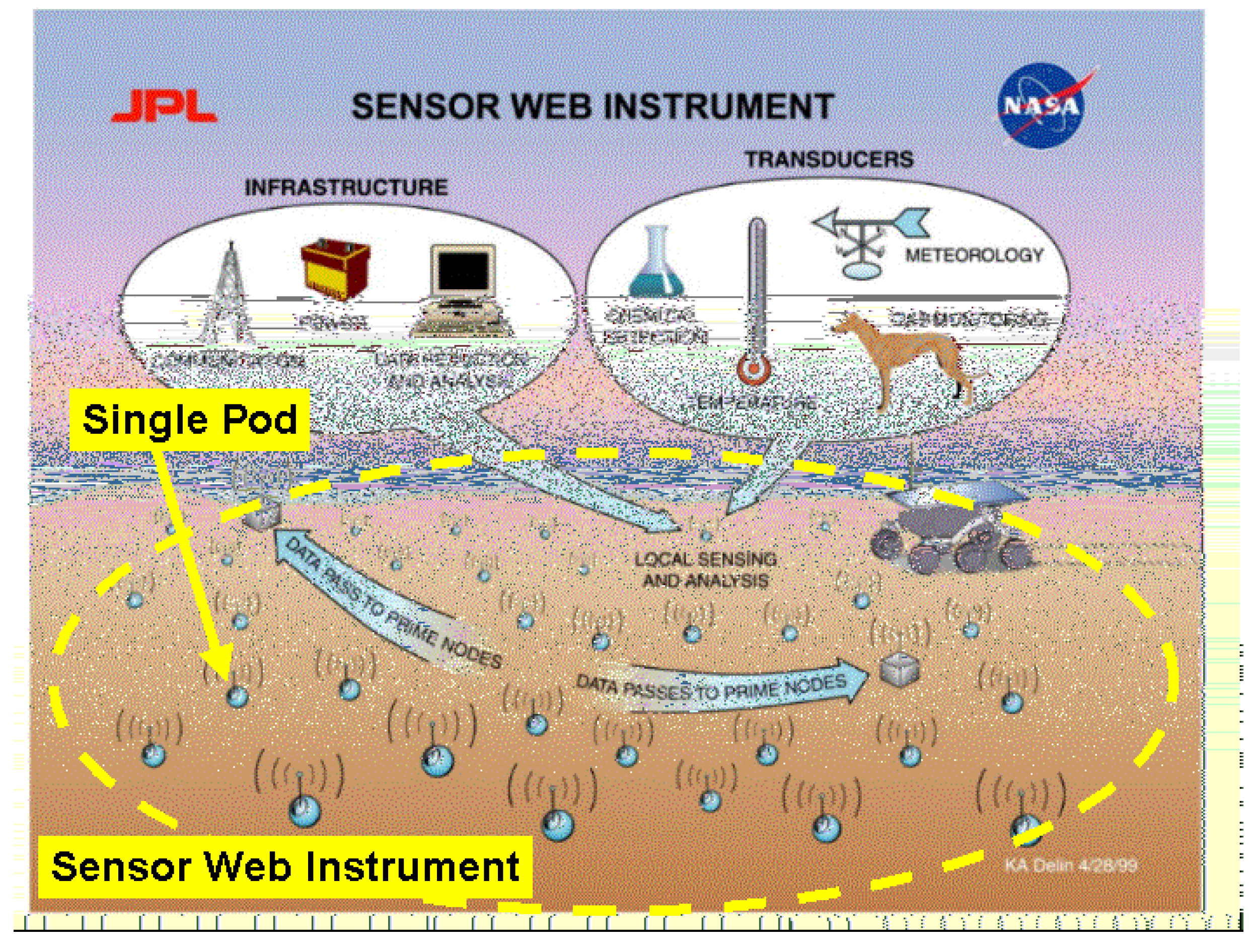
In Situ Sensor Webs
From this point forward, we will focus almost exclusively on in situ Sensor Webs. An example schematic of such an instrument is shown in Figure 3. It is critically important to recognize that the individual pods in the Sensor Web are not the actual instrument. The macro-instrument is comprised of the sensor pods and the space between them, just as the brain is composed of the individual neurons and the synaptic regions between them.
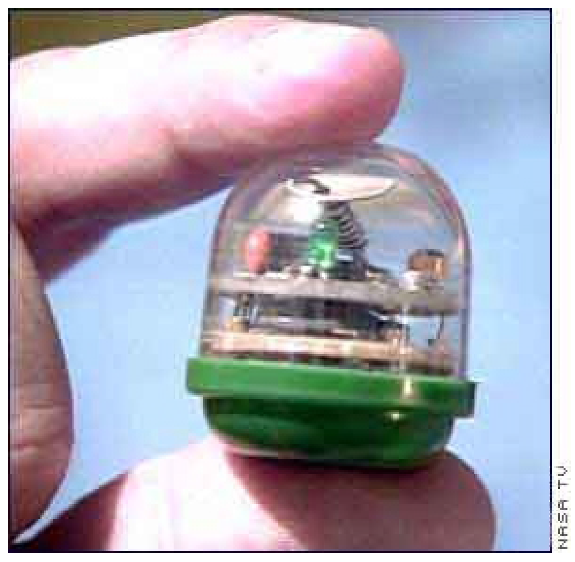
An example of an actual Sensor Web pod is shown in Figure 4. This pod, constructed at JPL in 1999, was used to demonstrate the validity of the Sensor Web concept. The small pod contains a radio transmitter and receiver, microcontroller, lithium battery (hidden in the base), and two sensors to monitor light levels and temperature. The total pod mass is about 50 g. Over a duty cycle of one set of measurements per second, it is estimated that 50 microwatts of power are needed. Further details of this pod may be found elsewhere [4]. At the time, the total cost of parts was less than $50 demonstrating the tremendous power of leveraging commercially available parts.
Sensor Webs are often confused with projects that fall under names such as “distributed sensors” or “sensor networks”. The most unique feature of the Sensor Web is that information gathered by one pod is shared and used by other pods. Distributed sensors networks merely gather data and communicate it to an uplink point. Examples include the seismology networks present in Southern California. Typically, in a distributed sensor system, the information is purposefully routed directly to the end-user. The information gathered by a particular pod on such a network typically does not influence the behavior of another pod, especially a pod that is not on the route between the data collection point and the end-user. In contrast, the purpose of broadcasting information on a Sensor Web is to share the information with other pods. That the knowledge obtained by the instrument reaches the end-user is almost incidental to the operation of the instrument. If, for example, one pod should cease functioning, its lost presence could cause neighboring pods to increase their sampling rate to gain in time resolution what has been lost in spatial resolution. Thus we find that distributed sensors collect data while a true Sensor Web can digest the collected data and even modify its behavior on the basis of this processed knowledge. There is a global, macroscopic “purpose” to data collection by Sensor Web pods that is not apparent in the distributed sensor network.
Figure 3.
Sensor Web concept as applied to an in situ terrestrial environment. The Sojourner rover of the Mars Pathfinder mission is provided for scale.
Figure 3.
Sensor Web concept as applied to an in situ terrestrial environment. The Sojourner rover of the Mars Pathfinder mission is provided for scale.

Figure 4.
Sensor Web 1 pod.
In Situ Sensor Webs versus Other Monitoring Techniques
An in situ Sensor Web provides a different type of measurement capability than that associated with remote techniques made by orbital or airborne platforms. By definition, remote measurements require a high degree of knowledge of the physics of the measurement to infer value from the collected data (interpreting ocean currents or a vegetation index, for example). In contrast, a Sensor Web can provide direct, proximity measurements over a large spatial scale whose value is much more immediate. Moreover, unlike remote measurements made by orbital or airborne platforms, a Sensor Web provides a continued, virtual presence in an area. This is particularly important when investigating phenomena of a transient nature where there is no guarantee that an orbiting instrument will be in position to record the event. Finally, remote measurements cannot reach certain areas such as inside buildings or beneath ocean and Earth surfaces. An in situ Sensor Web, by definition, does not have this limitation as it is placed directly within the environment of interest.
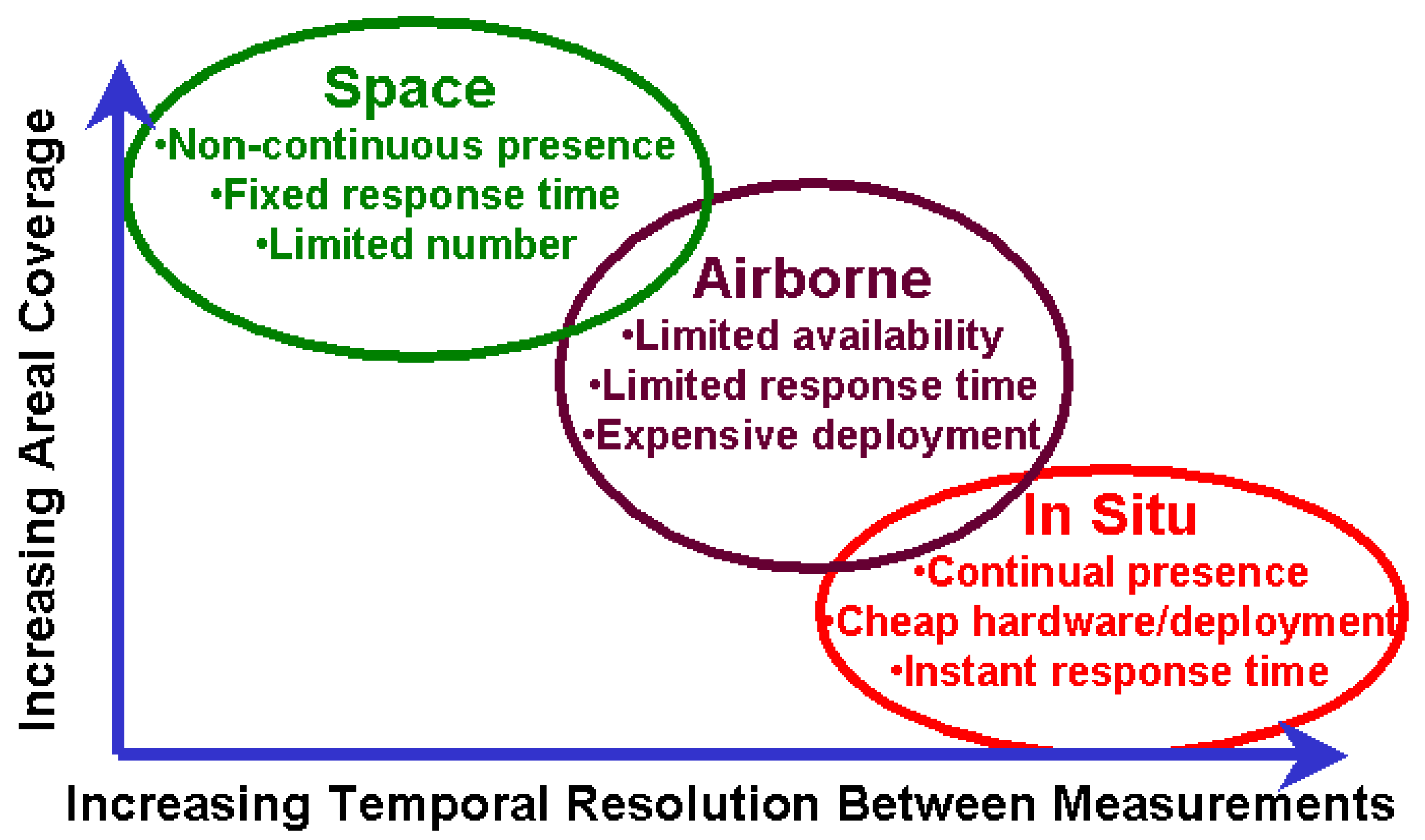
Figure 5.
Regions where different measurement techniques dominate.

As a specific (though exotic) example of the interplay between a Sensor Web and orbital measurements, consider the problem of searching for life on Mars. Because bacteria are thought to be the most primitive and ancient life forms on Earth, they are the logical target for investigating life via remote sensing. An example of such an instrument for this purpose is the interferometer-based Terrestrial Planet Finder [5]. This instrument probes atmospheres of extra-solar planets for gases that are out of chemical equilibrium; the disequilibrium potentially caused by biological activity. Planets that harbor significant amounts of bacterial life will possibly have a metabolic signature in their atmospheres. To investigate biological signatures in the Martian atmosphere, however, remote sensing technologies are not adequate because the small volumes of any biologically produced gas disperses rapidly over the surface. Moreover, the likely transient nature of the respired gases might be missed by any orbiting instruments that fly over a specific position only at certain times. Therefore, in situ gas sensors are required for detecting traces of any extant biogenic gas emissions. The likely starting place to deploy these sensors would be where water is thought to have once existed. The specific placement is problematic, however, since orbital topographical measurements continue to indicate that there are vast regions of Mars that might once have had surface water [6]. It is simply not practical to land expensive, dedicated spacecraft all over the entire Martian surface. In contrast, Sensor Webs equipped with gas sensors might be able to narrow the search space from those given by the orbital measurements to a much smaller region suitable for a single lander. As a result, the Sensor Web is an instrument capable of scientific surveying on spatial scales between those of an orbital platform and those of a lander [7].
Of course, Sensor Webs will not replace remote measurements or autonomous vehicle measurements but rather provide a new, unique capability. As shown in Figure 5, there is a trade-off between the area coverage and temporal resolution of measurements. In situ Sensor Webs can therefore augment previous techniques by providing crucial ground-truth and calibration data for space-based remote measurements or large-scale, but spatially static, intelligent networks to direct the motion of autonomous vehicles.
In Situ Sensor Web Requirements
Because the Sensor Web is not a one-size-fits-all solution, each instrument must be designed specifically for the needs of a particular task. Nevertheless, if the Sensor Web infrastructure is costlier, heavier, and more power-hungry than its component sensors, it will be of little practical use. As a result, there are three basic design goals that a well-engineered in situ Sensor Web must address: micro-power, micro-bandwidth, and micro-cost.
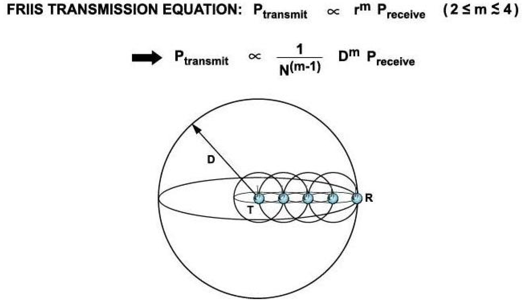
Figure 6.
To communicate data from pod T to pod R, multi-hopping is more power efficient than simple direct transmission. The spheres represent where power is transmitted in the case of free space.
Figure 6.
To communicate data from pod T to pod R, multi-hopping is more power efficient than simple direct transmission. The spheres represent where power is transmitted in the case of free space.

The first requirement, that of power minimization, is dealt with by hopping the data pod to pod since this not only allows for sharing locally collected data but also is power efficient. From elementary electromagnetic theory, the total power required to transmit a signal that ensures a received power Prec a distance D away is Ptran∝(D/λ)mPrec where λ is the wavelength of the transmitted signal [8]. Here m is 2 in free space and can range to 4 or more in environments with multiple-path interferences or local noise. As a result, the total power required to transmit a given distance with N hops is reduced by a factor of N(m-1) compared to the total power required by direct transmission. In the simple case of free space (m=2), this fact is easily demonstrated graphically as shown in Figure 6. It is clear from the figure that the surface area of the collection of smaller spheres (multi-hop transmission) is much less than that of the larger one (direct transmission). The reason why hopping data is power efficient is that more of the power is directed along the path to the receiver. Since the free space case is the best-case scenario in terms of transmission efficiency, the value of hopping is only increased in more hostile environments.
The second requirement, that of bandwidth minimization, is similarly handled by a previously defined Sensor Web objective: deduce knowledge from raw information. As the Sensor Web pods communicate via low-power wireless radio, high baud rates are unlikely. Fortunately, for many applications, it is the knowledge obtained by fusing the raw data collected that is essential. For example, the directional flow of effluents for a remediation application may be of interest rather than the specific concentrations at every location. The calculated gradients represent a natural compression of data as the local concentrations are measured, shared with other pods, and processed. Similarly, identification of a tank versus a truck can be accomplished via fusing measurements of exhaust fumes, ground vibrations, and magnetic signatures. Again, the raw data is not of interest and the pods need only broadcast the tank presence while possibly even ignoring trucks altogether.
The final goal of Sensor Web design is to minimize the cost of each pod. As we have seen, the use of commercial-off-the-shelf (COTS) component parts allows for rapid development and low-cost pods. In addition, by building a core Sensor Web technology including pod-to-pod protocols, data fusion and management, and robust packaging, design efforts for a variety of similar environments may be leveraged using plug-and-play sensors that are application specific.
Sensor Web Organization
The very essence of a Sensor Web, with its multiply redundant pods, allows for an instrument to be “reseeded” against instrument degradation. In other words, as various pods drop out of the web because of spent batteries or damaged transducers, it is possible to deploy new pods in the instrument area that will seamlessly mesh with the existing, older web communication backbone. In this way, though the pods themselves are expendable, the Sensor Web instrument can continue to function indefinitely. Moreover, this reseeding allows the macroinstrument to evolve over time, as new pods can be more sophisticated and technologically advanced than older ones. Because the Sensor Web has no definitive boundaries (the mother pods may be located anywhere in the network), multiple deployments of webs in a given area will naturally mesh with one another. Consequently, a Sensor Web represents an instrument whose surveying area can be expanded via multiple deployments.
There is no preferred direction of information flow on the Sensor Web. Although the mother pods provide a point of access into and out of the Sensor Web, there is no assumed directionality or “focusing” the data collected by individual pods towards the mother pods. This allows the Sensor Web instrument the complete flexibility just described: Pods can be dropped in or out at random points in space and time and mother pods may be added to grow the extent of the web. Unlike a star-network, in which a mother pod must be centrally located, mother pods in a Sensor Web may be distributed wherever convenient. The assumed omni-directional wireless communication between pods further reduces rigid placement requirements in a Sensor Web.
In addition to omni-directional communication, the radio traffic is also bi-directional. In other words, there is no preferred direction within the peer-to-peer network. At first this may seem obvious, yet when applied to the communications associated with the mother pod, powerful results occur. Because the end-user interacts with the Sensor Web via the mother pod, the bi-directional communication property allows the user not only to receive information from the Sensor Web, but also send instructions into it. As a result, the Sensor Web is a field-programmable instrument.
To formalize these notions, we define a “pod” as a physical piece of hardware containing the two modules of transducers and infrastructure as described above. In contrast, a “node” is a logical (or abstract) construct that simply is a vertex on a Sensor Web. A node can be either a pod or another Sensor Web. Thus a Sensor Web can be viewed recursively as a web of webs as illustrated in Figure 7. Any “spherical” pods dropped at random into this web will, with a higher probability, tend to be associated with a single mother pod and thus, a particular sub-web. Consequently, a scale-free hierarchy emerges which is quite robust with respect to random pod dropout [9,10]. Interestingly, there are indications that nervous systems may be modeled on similar ideas, again invoking a strong analogy between the Sensor Web and the brain.
Figure 7.
The scale-free nature of the Sensor Web. Notice the first tier of mother pods (cubes) form their own web structure, leading to the idea that the Sensor Web is a web of web nodes. Individual (spherical) pods are not necessarily associated with a particular mother pod, although most tend to be.
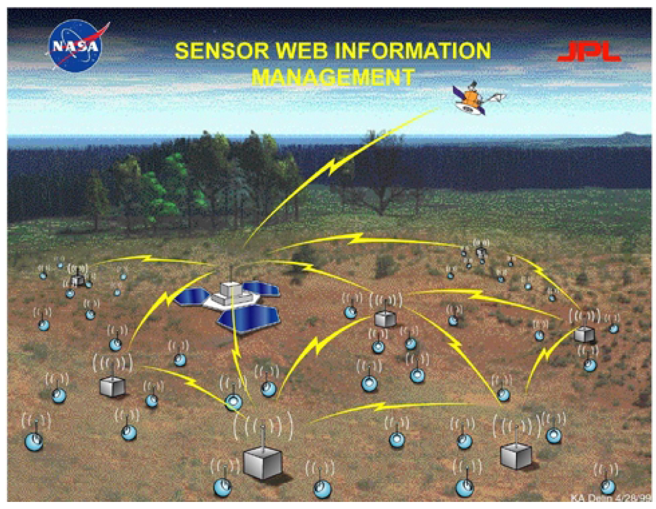
Figure 8.
A Macro-Sensor Web comprised of individual webs can collect and process in situ data over vast regions of space.
Figure 8.
A Macro-Sensor Web comprised of individual webs can collect and process in situ data over vast regions of space.
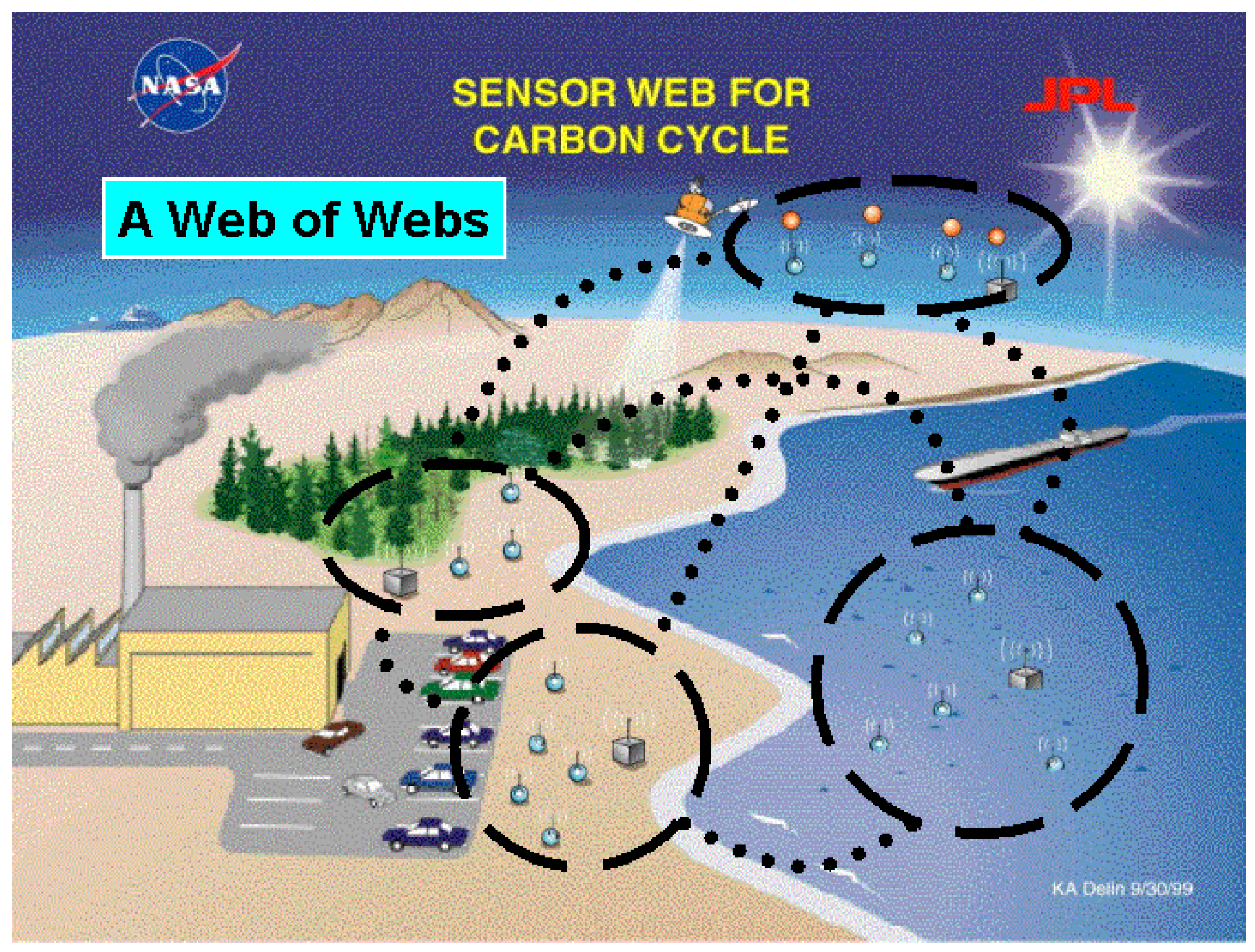
We can carry this web-of-webs idea one step further. The end-user of a Sensor Web may be, in fact, another Sensor Web. The bi-directionality of Sensor Web communications allows the mother pods to be linked (by the Internet or satellite) which allows the Sensor Web to leap beyond the bounds of a local spatial confinement. This idea may become critically important for a very large-scale environmental study such as the examination of the carbon cycle on Earth. Remote techniques have not yet fully revealed how the Earth recycles its elements over its diverse ecosystems. As shown schematically in Figure 8, the Sensor Web concept is ideal for probing detailed chemical motion throughout ecosystems, such as across ocean-air interfaces or along subterranean water flow. These areas cannot be studied directly by remote techniques and so the Sensor Web, once again, provides the ideal method for obtaining the capability normally associated with an in situ measurement over a spatial expanse normally associated with a remote measurement.
Sensor Webs at JPL
The JPL Sensor Webs Project [11] was formed to explore the value of the Sensor Web concept in various applications and push the technology of the instrument itself. The project would leverage the technology revolutions in the computation and telecommunication industries and primarily focus on applying (rather than developing) the required hardware. The applications themselves would determine the specific structure of the pods and the sensors needed.
The first and second generation Sensor Webs produced are described in detail elsewhere [12]. Briefly, Sensor Web 1 demonstrated the viability of the concept in the laboratory, while Sensor Web 2 demonstrated the instrument in the field. A botanical greenhouse was chosen as the initial deployment site for several reasons. First, many basic applications, particularly those in astrobiology and Earth science, require a suite of sensors similar to those needed in this environment. Second, a greenhouse would provide somewhat harsh conditions (high temperatures, high humidity, exposure to dust, etc.) to make a field test meaningful while at the same time provide a reasonably protected area for the Sensor Web to operate. Finally, such an environment could be found close to JPL at the Huntington Botanical Gardens in San Marino, California [13], allowing for convenient access over the course of the testing.
Sensor Web 2 was activated on May 18, 2000. Every five minutes, 24 hours a day, 7 days a week, each pod recorded the state of its transducers (air temperature, soil temperature, relative humidity, O2 level, soil moisture, light level) and its internal voltage. Although initially planned as a two-week test, Sensor Web 2 proved quite robust and collected data continuously in 5 minute intervals for over 22 weeks.
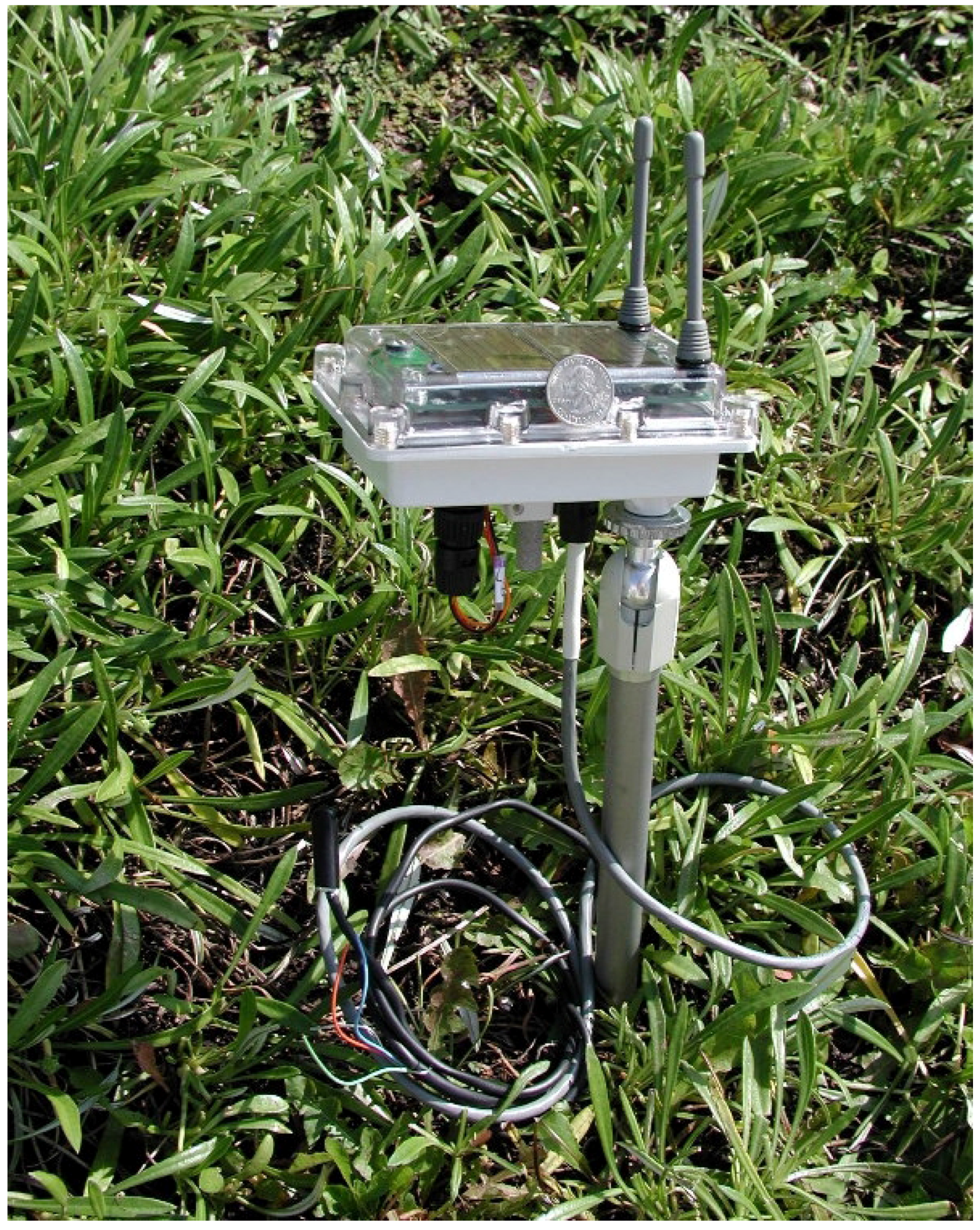
Sensor Web 2 was so successful that work immediately began on Sensor Web 3. A typical pod is shown in Figure 9. Sensor Web 3 was similar to Sensor Web 2 in a number of ways. Communications were handled by a pair of commercial receiver and transmitter boards (916 MHz). These micropowered units handle data at rates of up to 50 kbs and have an open field range of over 150 m. Our system uses burst transmissions at 28.8 kbs. A microcontroller coordinates the radio and sensors and executes the Sensor Web protocols. Moreover, the unit is powered by a nominally 8 V battery that is trickle-charged by solar cells. To prevent extreme battery drain, each pod monitored its own power consumption and was instructed to sleep should voltage levels drop too much. The pod would wake up after sunlight charged its battery to sufficient levels again. Finally, the same commercially available sensor set was used and is detailed in Table 1.
Figure 9.
Sensor Web 3 pod. Note the quarter resting on the top. Sensors meant for subterranean measurements (temperature, moisture) can be separately connected as shown.
Figure 9.
Sensor Web 3 pod. Note the quarter resting on the top. Sensors meant for subterranean measurements (temperature, moisture) can be separately connected as shown.

| Environmental variable | Measurement units | Accuracy |
|---|---|---|
| Soil moisture | cbars electrical resistance | ±10% vs. tensiometer |
| Photosynthetic photon flux | μmol photons m-2 s-1 | ±3% |
| Temperature (air, soil) | °C | ±0.75° |
| Relative humidity | % | ±2% |
There were numerous improvements as well. First, the sensor interface was designed to be modular and not hardwired into the pod. Consequently, subterranean sensors could now be planted first and then quick-connected into the pod as a second step which greatly speeds deployment. The package for the pods was redesigned to handle relatively large temperature swings (-55C to +70C) and to be impervious to dust particulate and intense water sprays. The plastic box was not made to be submersible yet is able to withstand a few inches of water pressure for about 10 minutes before leaking. The pod circuitry was redesigned to be mass-produced. Finally, the microcontroller in the pods was upgraded to take advantage of the progress made by commercial chip manufactures.
Figure 10.
Browser-based GUI for Sensor Web as it appears on the desktop.
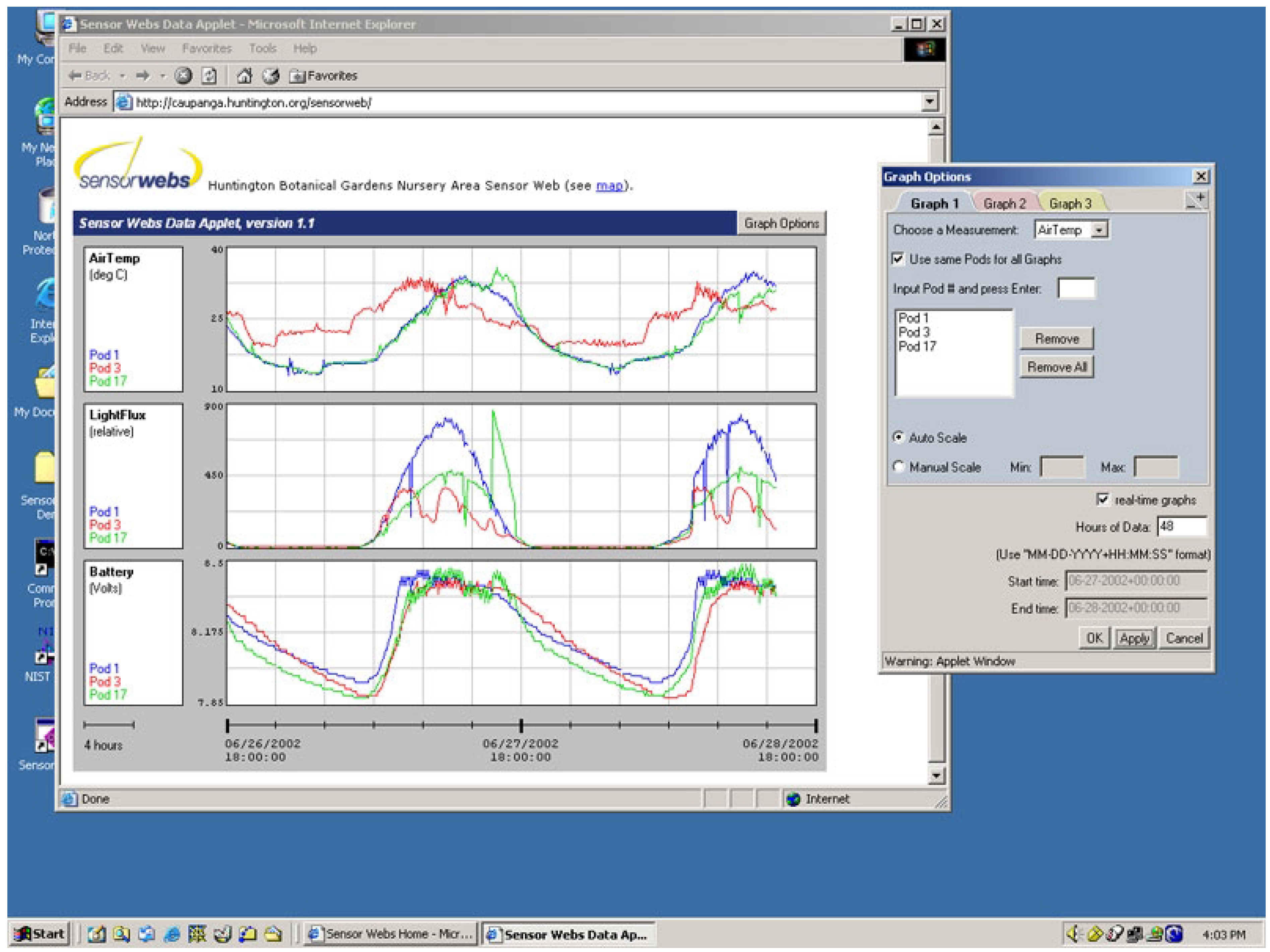
The last major difference between Sensor Webs 2 and 3 was the end-user interface. In an effort to make the data from the Sensor Web universally available, a Graphical User Interface (GUI) was designed to be activated in a web browser, require little training to use, and operate reasonable rapidly over a 56 kbs modem. The resulting GUI display is shown in Figure 10. The GUI, which consists of an applet embedded in a webpage, was successfully tested under both Netscape and Internet Explorer browsers on PC machines, Internet Explorer on Apple machines (under OS X), and Netscape on Linux machines. Both real-time, streaming data and archived data are available with this applet and pods and measurements can be examined at will.
Sensor Web Deployments [14]
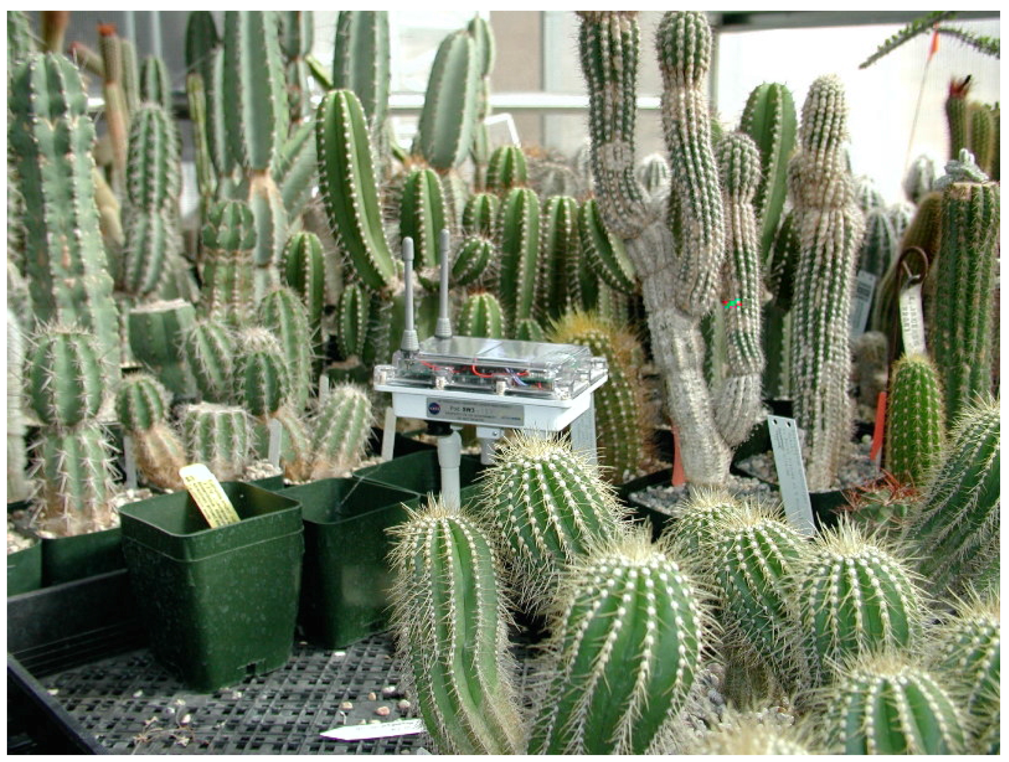
The first Sensor Web 3 instrument was deployed in the same test site at the Huntington Gardens as Sensor Web 2. This test site, shown in Figure 11, is approximately 50×100 m2. The size of this Sensor Web was determined by the application environment and not from limitations of the instrument itself. The application area was chosen because there are four, well delineated, sub-environments within it, making it easy to spot check sensor data. First, a rooftop on a storage shed was available for local weather conditions. Next a four-zone wet (propagation) greenhouse would hold the densest set of pods. The propagation house is a closed environment and misters operated both from the ceiling and ground-level tables creating high relative humidity and warm temperatures. Pod 14 was situated underneath the sole temperature and relative humidity sensors that monitor the entire greenhouse. This pod provided the calibration test of the Sensor Web to the existing greenhouse sensors (which are assumed to be accurate). The third sub-environment is a desert (cactus) greenhouse (see Figure 12). Unlike the wet greenhouse, this area was open as the sidewalls were a wire mesh allowing for ambient conditions to exist across the entire greenhouse. For this reason, only three pods were deployed there. Pod 6 was placed under the sole temperature and relative humidity sensors monitoring this area. Finally, the last sub-environment was an outdoor nursery covered by a tarp. The mother pod (indicated by a “0” on the map) was located in an office area where electrical power was available for the laptop computer used to serve up the data.
Figure 11.
Map of Sensor Web 3 at the Huntington Garden. Note the size of the cars pictured.
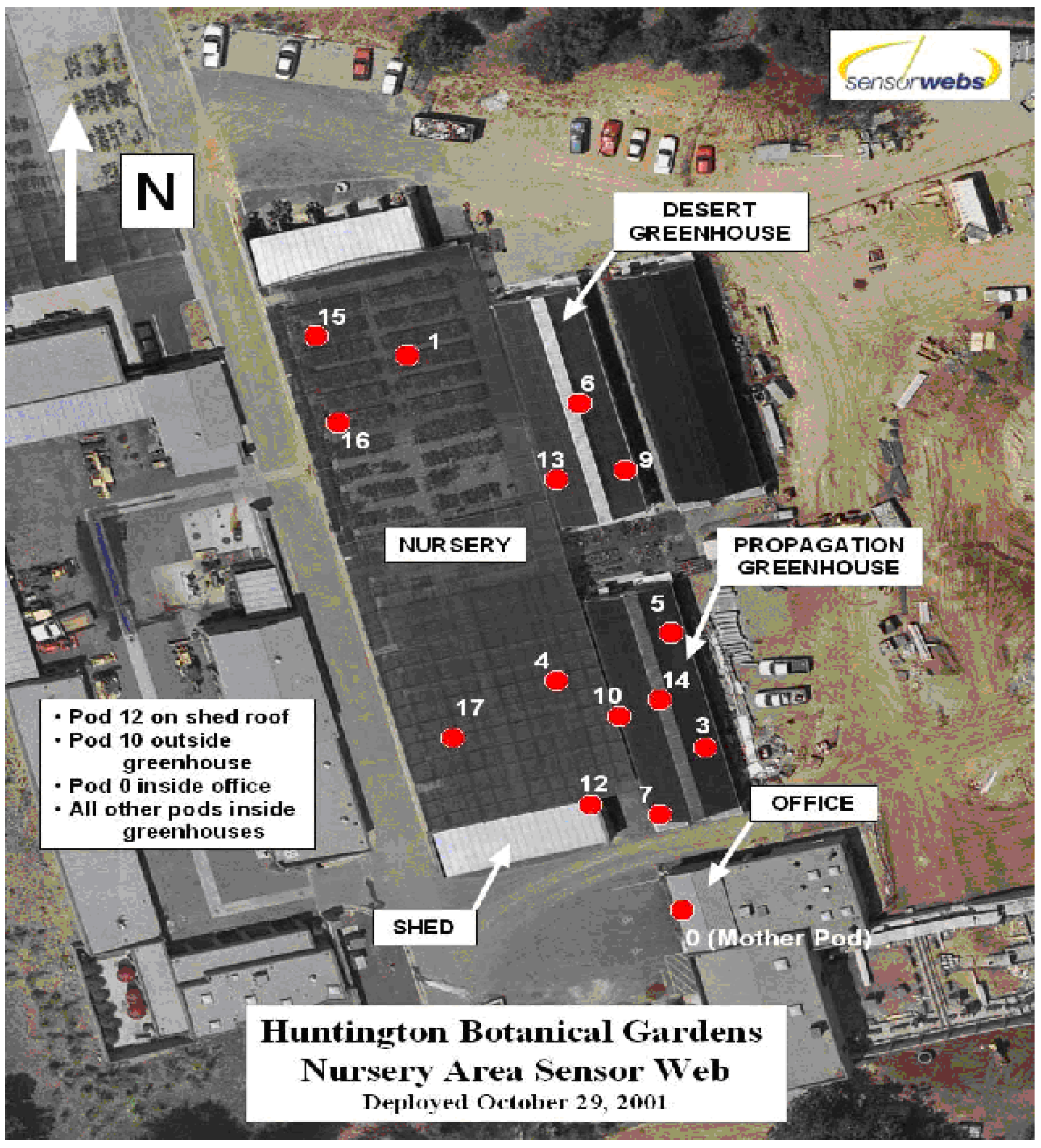
This Sensor Web was activated on October 29, 2001 and has been taking measurements every 5 minutes, 24 hours a day, 7 days a week ever since [15]. The calibration tests at pods 14 and 6 checked out with the existing sensors to within the accuracy of the measurements. The pods showed a remarkable robustness and have operated well despite this test running during the winter months of relatively low-light conditions thus limiting solar energy harvesting.
The next deployment was at Lancaster Farms located in Suffolk, Virginia. This 8-pod deployment, also at the end of October 2001, was not conducted by the Sensor Web team from JPL. Instead, the pods were shipped cross-country and installed by workers unfamiliar with Sensor Web operations. Nevertheless, they had no difficulty in setting up the system. In addition, this was the first truly outdoor deployment. Again, the pods were environmentally robust with only one failure occurring after 7 months of operation (a pod was situated directly under a sprinkler and it eventually leaked). Moreover, after 6 months of continuous operation, the web was expanded by 3 pods. The network was able to self-reorganize and continued to operate with the additional pods.
Figure 12.
Sensor Web 3 pod deployed in the desert greenhouse at the Huntington Botanical Gardens.

Figure 13.
Sensor Web 3 pod deployed at the Kennedy Space Center. Note shuttle launch Pad 39A less than 1 mile from the site.
Figure 13.
Sensor Web 3 pod deployed at the Kennedy Space Center. Note shuttle launch Pad 39A less than 1 mile from the site.

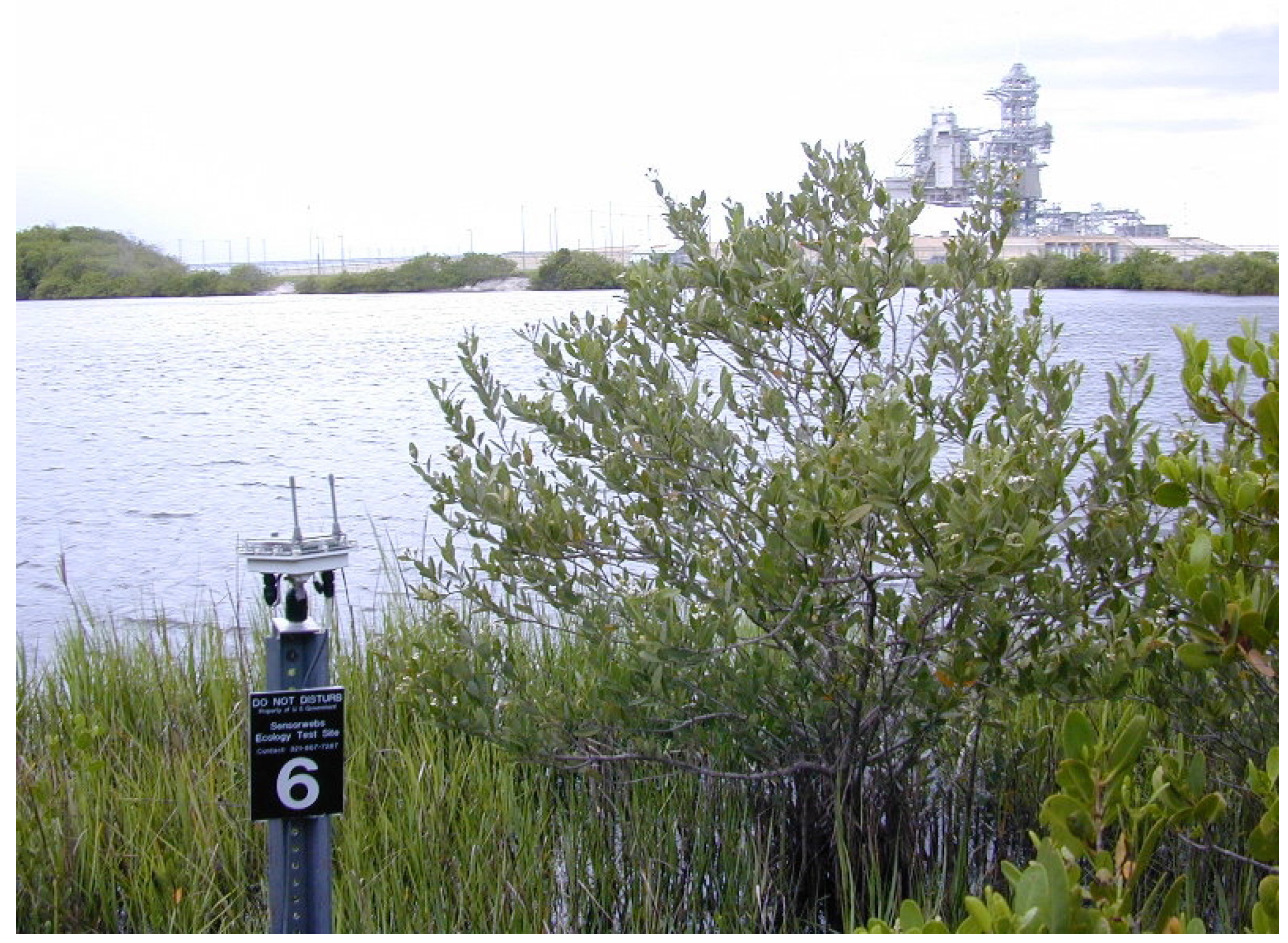
Another Sensor Web 3 was recently deployed at the Kennedy Space Center in Florida. Here the Sensor Web will be tested in a totally new environment and will be subjected to salty air, intense summer heat, and lightning. The Sensor Web itself will be used to monitor the northern terminus of the Banana River Lagoon adjacent to the space shuttle launch site Pad 39A (see Figure 13). This marine ecosystem is particularly rich with fish and other life and the Sensor Web instrument will monitor physical parameters, such as water temperature, in order to characterize the dynamics of the habitat. Although the pods will remain above water (for communication purposes), the sensors will be wired to them and placed into the roughly 1 m deep lagoon. It is expected that the web will be cleared to operate during shuttle launches and will therefore provide important data about the impact of a launch on the local ecosystem.
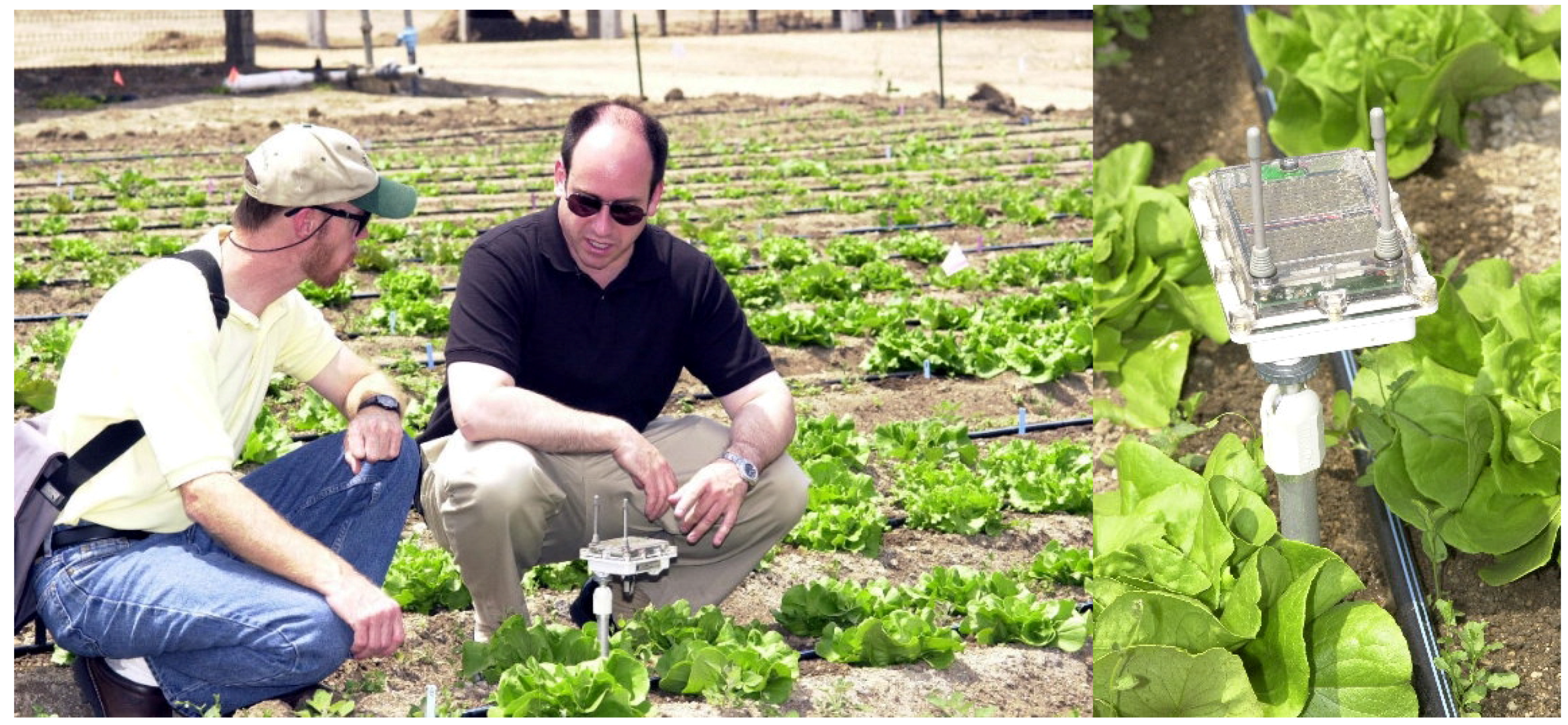
The fourth Sensor Web 3 that became operational is at an agricultural site at Cal Poly Pomona in Southern California. Here the goal is to understand the microclimates possibly affecting the growth of lettuce over a small field (Figure 14). The continual monitoring is particularly important as the data collected will be over the entire growth cycle of the plants. Initial pod sensors will be air and soil temperature, humidity, and soil moisture. In the future, Sensor Webs may become an important means to perform precision agriculture, providing farmers with a detailed knowledge of their fields at relatively low cost.
Figure 14.
(a) The author (right) and Prof. David Still discuss a Sensor Web 3 pod deployed in a lettuce field. (b) Close-up of pod. Note the dirt and residue on the package.
Figure 14.
(a) The author (right) and Prof. David Still discuss a Sensor Web 3 pod deployed in a lettuce field. (b) Close-up of pod. Note the dirt and residue on the package.
Summary
It should be clear from these examples, that the in situ Sensor Web is rapidly becoming a stable platform with which to link together various sensors. It is expected that as more commercial, mass-produced, low-power, low-cost sensors become available, the possible applications for Sensor Webs will grow even further.
Sensor Web technology is just reaching the point where it can drive sophisticated scientific applications. At JPL we have demonstrated the basic Sensor Web protocols, built pods that can be assembled in a low-cost manner, shown the robustness of a long-lived system in the field, and fully realized the end-to-end solution between sensors in the field and data management from the Internet. We have just begun to test the Sensor Webs in different environments and soon expect to generate scientifically significant data with our instruments.
The future of Sensor Web technology looks bright as well. As computational capabilities continue to follow Moore’s Law, it will soon be possible to locally correlate and fuse the non-local data within the pods as described in this paper. This is a key step in instrument self-awareness. Consequently, it is expected that the Sensor Web will become a ubiquitous instrument in the future, particular for applications requiring an intelligent, virtual presence.
Acknowledgements
I would like to thank the members of the JPL Sensor Webs Project team for their continued innovations and enthusiasm: Shannon Jackson, Joel Britton, Scott Burleigh, Jaime Dyk, Dave Johnson, Ken Manatt, Myche McAuley, and Richard Woodrow. I am also indebted to Lonne Lane, Loren Lemmerman, and Philip Moynihan for many invaluable discussions that have shaped the Sensor Web concept and its potential applications. I also acknowledge the support of my colleagues who have aided in fielding the Sensor Webs: Jeff Anderson, Jim Folsom, Grant Gilmore, Gail Goodyear, Cristina Guidi, Julie Holland, George Kantor, Mike Lane, Claude Robinson, Stefanie Saccoman, Sanjiv Singh, Wiley Splain, David Still, and Theresa Trunnelle.
The research described in this paper was carried out by the Jet Propulsion Laboratory, California Institute of Technology, under a contract with the National Aeronautics and Space Administration.
References
- Delin, K.A.; Jackson, S.P.; Some, R.R. Sensor Webs. NASA Tech Briefs 1999, 23, 80. [Google Scholar]
- Koch, C.; Laurent, G. Complexity and the Nervous System. Science 1999, 284, 96–98. [Google Scholar] [CrossRef] [PubMed]
- See, for example, ftp://ftp.hq.nasa.gov/pub/pao/pressrel/2000/00-065.txt.
- Delin, K.A.; Jackson, S.P. Sensor Web for In Situ Exploration of Gaseous Biosignatures. In Proceedings of 2000 IEEE Aerospace Conference, Big Sky, MT, March 2000.
- Beichman, C.A.; Woolf, N.J.; Lindensmith, C.A. (Eds.) The Terrestrial Planet Finder, JPL Publication 99-3. 1999.
- Malin, M.C.; Edgett, K.S. Sedimentary Rocks of Early Mars. Science 2000, 290, 1927–1937. [Google Scholar] [PubMed]
- Ken, Nealson. private communication.
- Sadiku, M.N.O. Wave Propagation. In The Electrical Engineering Handbook; R.C., Dorf, Ed.; CRC Press: Boca Raton; pp. 925–937. 1997. [Google Scholar]
- Barabasi, A-L.; Albert, R.; Jeong, H. Mean-Field Theory of Scale-Free Random Networks. Physica A 1999, 272, 173–187. [Google Scholar] [CrossRef]
- Albert, R.; Jeong, H.; Barabasi, A-L. Error and Attack Tolerance of Complex Networks. Nature 2000, 406, 378–382. [Google Scholar] [CrossRef] [PubMed]
- The homepage of the project is located at http://sensorwebs.jpl.nasa.gov/.
- Delin, K.A; Jackson, S. P. The Sensor Web: A New Instrument Concept. In Proceedings of SPIE Symposium on Integrated Optics, San Jose, CA, January 2001.
- See http://www.huntington.org/BotanicalDiv/HEHBotanicalHome.html.
- See http://sensorwebs.jpl.nasa.gov/resources/applications.html for more details about each particular deployment (including pictures and appropriate Internet links).
- See http://caupanga.huntington.org/sensorweb/ for current conditions at the Huntington Gardens.
- Sample Availability: Available from the authors.
© 2002 by MDPI (http://www.mdpi.net). Reproduction is permitted for noncommercial purposes.
Share and Cite
MDPI and ACS Style
Delin, K.A. The Sensor Web: A Macro-Instrument for Coordinated Sensing. Sensors 2002, 2, 270-285. https://doi.org/10.3390/s20700270
AMA Style
Delin KA. The Sensor Web: A Macro-Instrument for Coordinated Sensing. Sensors. 2002; 2(7):270-285. https://doi.org/10.3390/s20700270
Chicago/Turabian StyleDelin, Kevin A. 2002. "The Sensor Web: A Macro-Instrument for Coordinated Sensing" Sensors 2, no. 7: 270-285. https://doi.org/10.3390/s20700270