Negative Curvature Hollow Core Fiber Based All-Fiber Interferometer and Its Sensing Applications to Temperature and Strain

 , , , , ,
  and
and 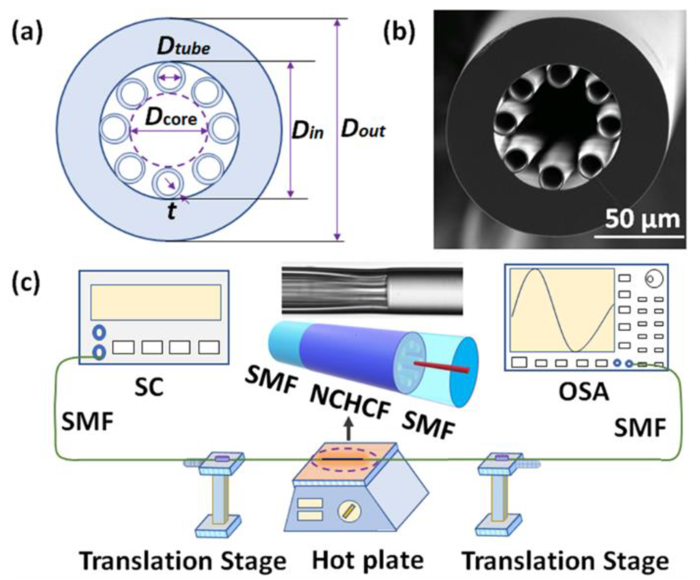
Abstract
:1. Introduction
2. Experimental Setup
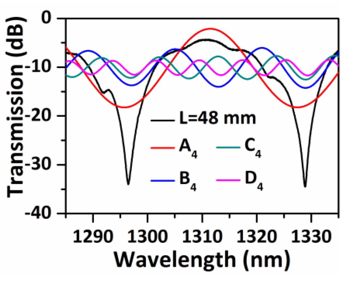
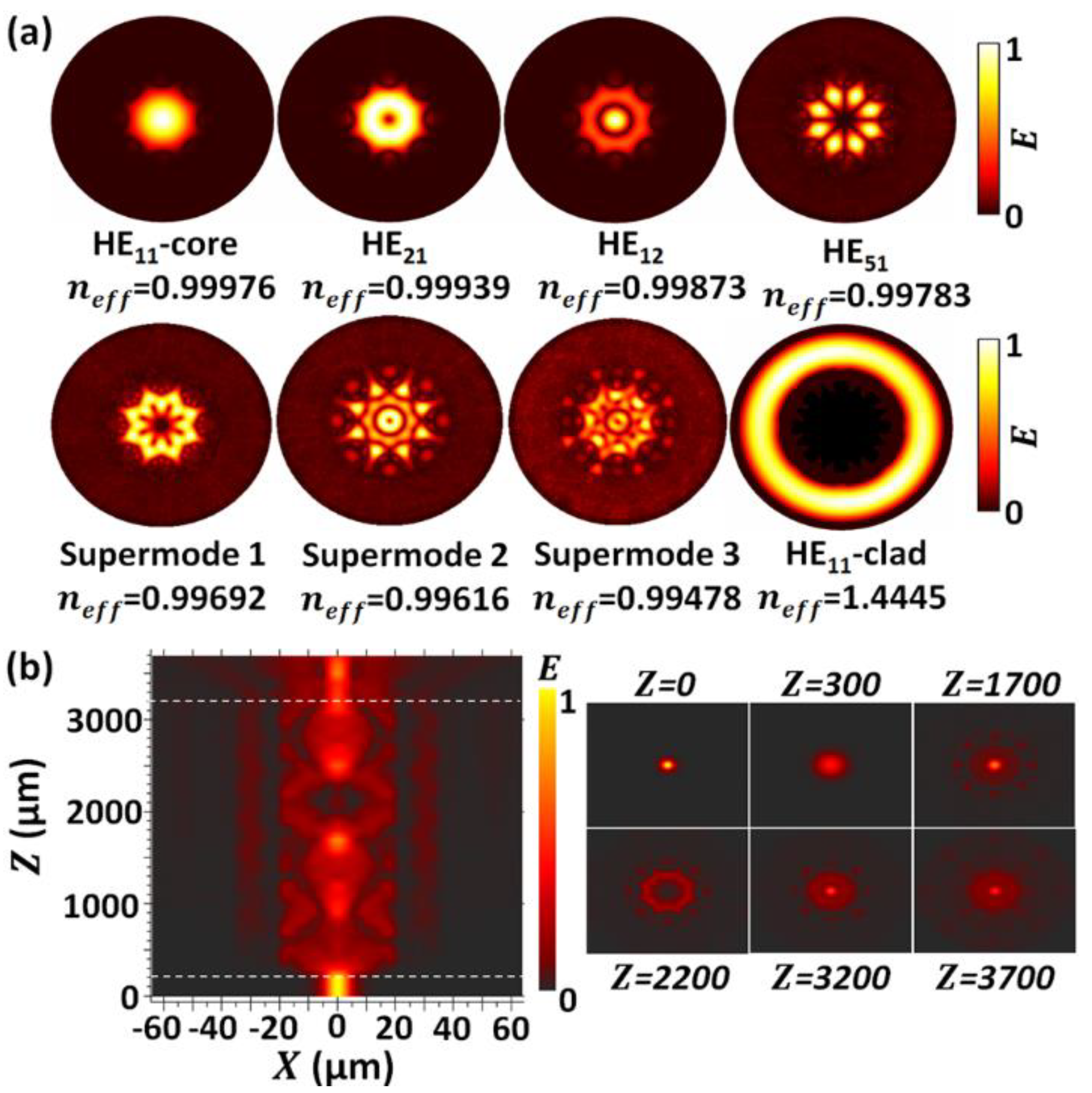
3. Theoretical Analysis
4. Results and Discussion
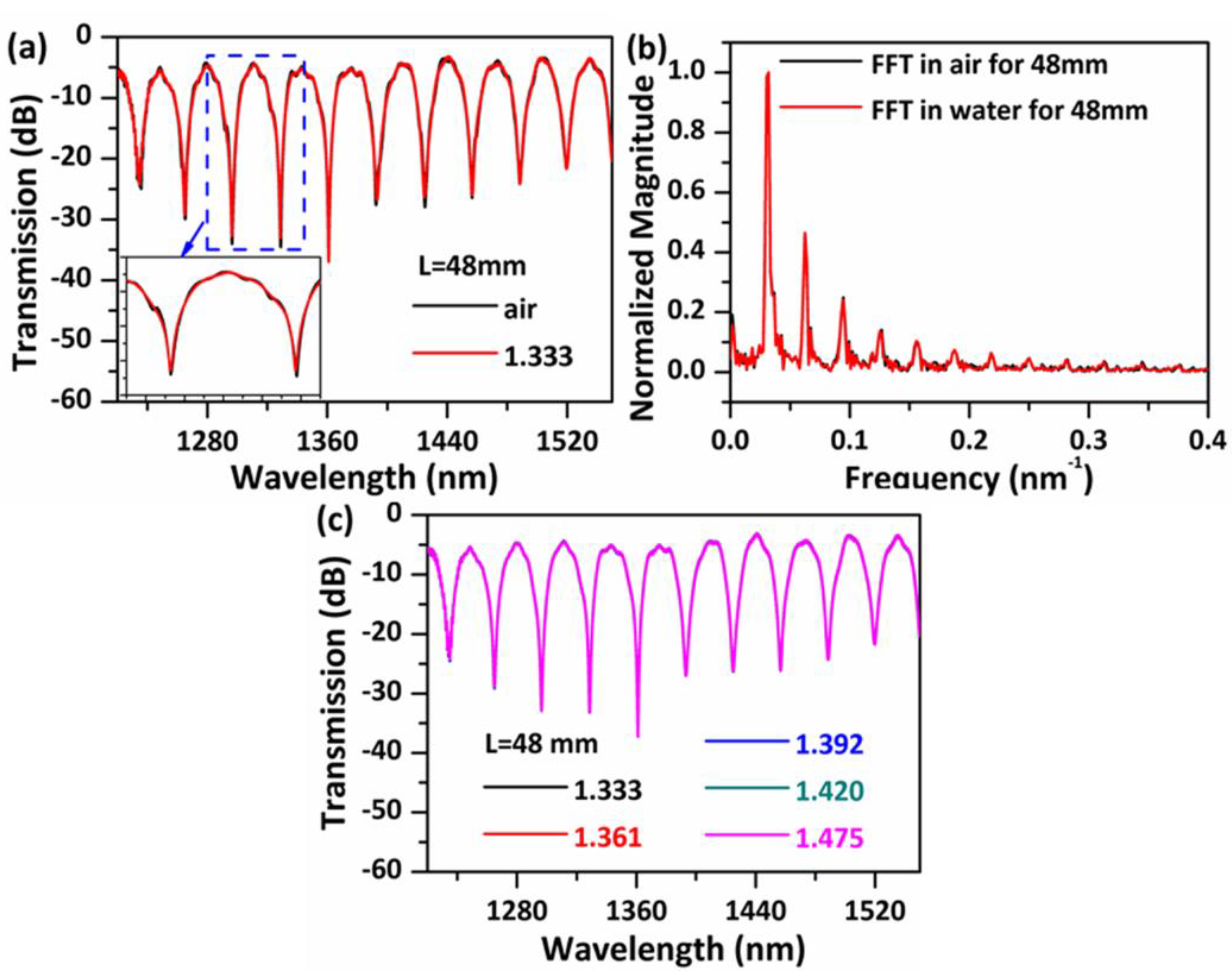
4.1. Spectral Response in Air
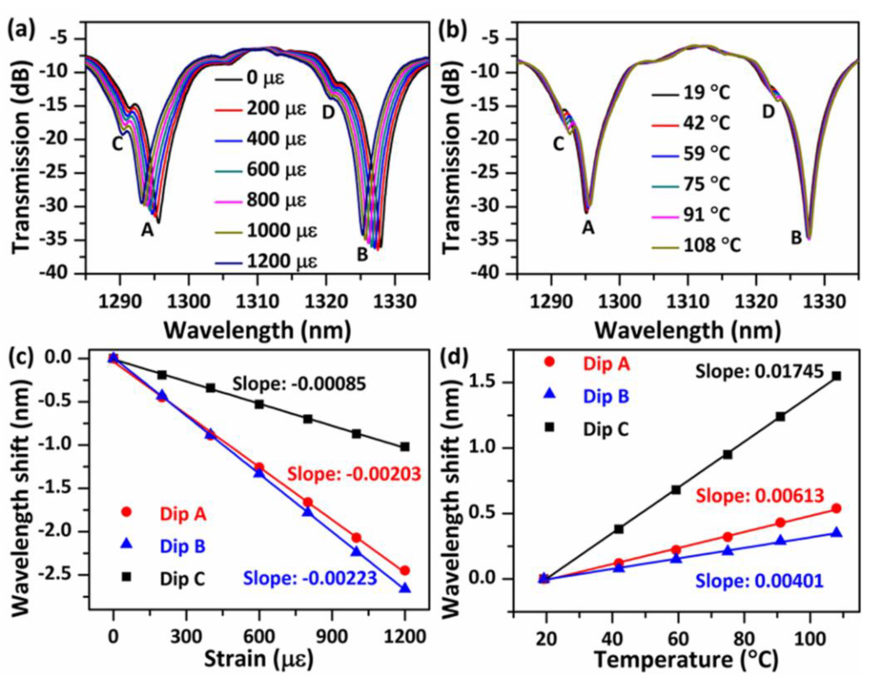
4.2. Temperature and Strain Measurement
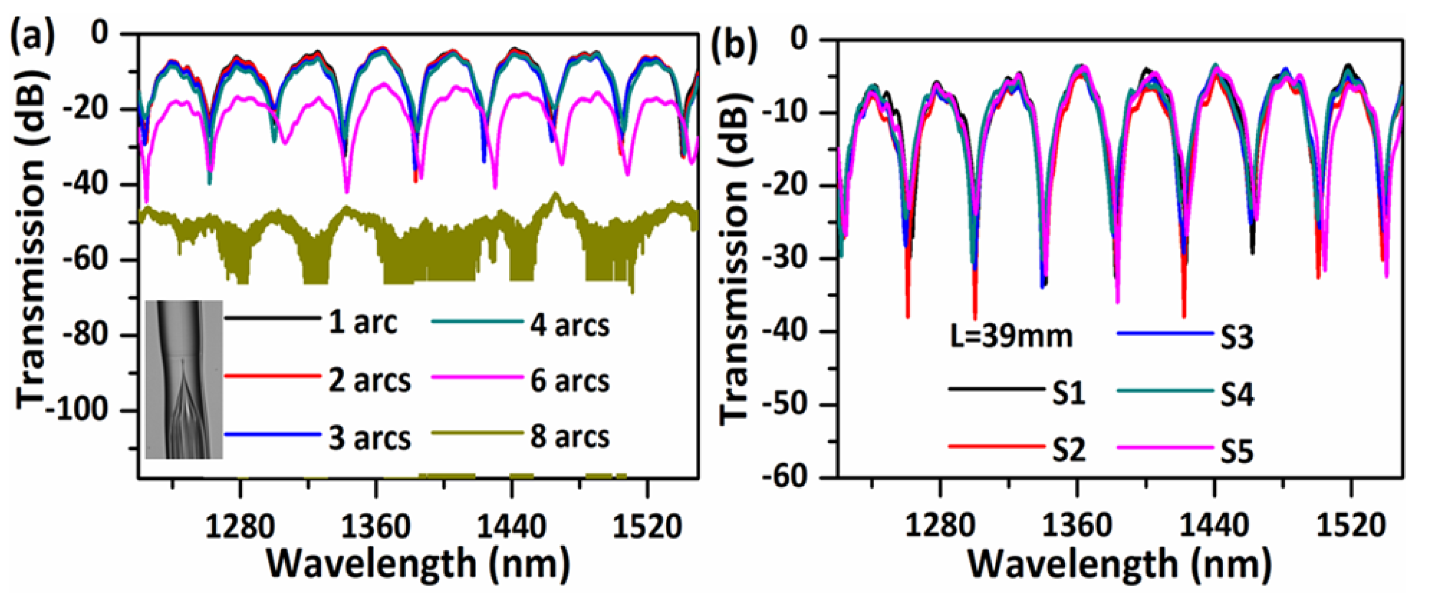
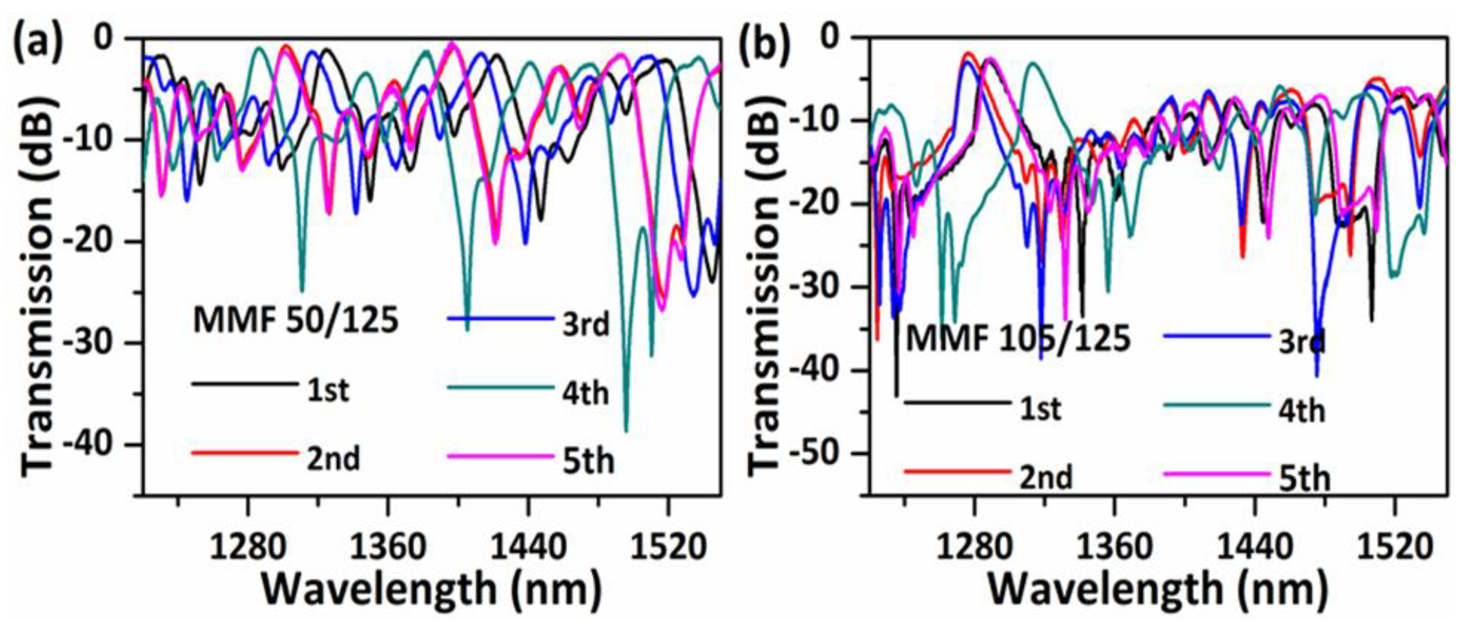
5. Reproducibility
6. Conclusions
Author Contributions
Funding
Conflicts of Interest
References
- Lee, B.H.; Kim, Y.H.; Park, K.S.; Eom, J.B.; Kim, M.J.; Rho, B.S.; Choi, H.Y. Interferometric fiber optic sensors. Sensors 2012, 12, 2467–2486. [Google Scholar] [CrossRef] [PubMed] [Green Version]
- Villatoro, J.; Finazzi, V.; Badenes, G.; Pruneri, V. Highly sensitive sensors based on photonic crystal fiber modal interferometers. J. Sens. 2009, 2009, 747803. [Google Scholar] [CrossRef]
- Wu, Q.; Semenova, Y.; Wang, P.; Farrell, G. High sensitivity SMS fiber structure based refractometer—Analysis and experiment. Opt. Express 2011, 19, 7937–7944. [Google Scholar] [CrossRef] [PubMed]
- Xia, L.; Li, L.; Li, W.; Kou, T.; Liu, D. Novel optical fiber humidity sensor based on a no-core fiber structure. Sens. Actuators A Phys. 2013, 190, 1–5. [Google Scholar] [CrossRef]
- Liu, D.; Mallik, A.K.; Yuan, J.; Yu, C.; Farrell, G.; Semenova, Y.; Wu, Q. High sensitivity refractive index sensor based on a tapered small core single-mode fiber structure. Opt. Lett. 2015, 40, 4166–4169. [Google Scholar] [CrossRef] [Green Version]
- Antonio-Lopez, J.E.; Eznaveh, Z.S.; LiKamWa, P.; Schülzgen, A.; Amezcua-Correa, R. Multicore fiber sensor for high-temperature applications up to 1000 °C. Opt. Lett. 2014, 39, 4309–4312. [Google Scholar] [CrossRef]
- Wang, Y.; Huang, Q.; Zhu, W.J.; Yang, M.H.; Lewis, E. Novel optical fiber SPR temperature sensor based on MMF-PCF-MMF structure and gold-PDMS film. Opt. Express 2018, 26, 1910–1917. [Google Scholar] [CrossRef]
- Rota-Rodrigo, S.; López-Amo, M.; Kobelke, J.; Schuster, K.; Santos, J.L.; Frazao, O. Multimodal interferometer based on a suspended core fiber for simultaneous measurement of physical parameters. J. Lightw. Technol. 2015, 33, 2468–2473. [Google Scholar] [CrossRef] [Green Version]
- Lin, C.; Wang, Y.; Huang, Y.; Liao, C.; Bai, Z.; Hou, M.; Li, Z.; Wang, Y. Liquid modified photonic crystal fiber for simultaneous temperature and strain measurement. Photonics Res. 2017, 5, 129–133. [Google Scholar] [CrossRef]
- Benabid, F. Hollow-core photonic bandgap fibre: New light guidance for new science and technology. Phil. Trans. R. Soc. A 2006, 364, 3439–3462. [Google Scholar] [CrossRef]
- Pryamikov, A.D.; Biriukov, A.S.; Kosolapov, A.F.; Plotnichenko, V.G.; Semjonov, S.L.; Dianov, E.M. Demonstration of a waveguide regime for a silica hollow—Core microstructured optical fiber with a negative curvature of the core boundary in the spectral region >3.5 μm. Opt. Express 2011, 19, 1441–1448. [Google Scholar] [CrossRef] [PubMed]
- Yu, F.; Knight, J.C. Negative curvature hollow core optical fiber. IEEE J. Sel. Top. Quantum Electron. 2016, 22, 1–11. [Google Scholar] [CrossRef]
- Wei, C.; Weiblen, R.J.; Menyuk, C.R.; Hu, J. Negative curvature fibers. Adv. Opt. Photonics 2017, 9, 504–561. [Google Scholar] [CrossRef]
- Wei, C.; Young, J.T.; Menyuk, C.R.; Hu, J. Temperature sensor based on liquid-filled negative curvature optical fibers. OSA Contin. 2019, 2, 2123–2130. [Google Scholar] [CrossRef]
- Silva, A.A.; Barea, L.A.M.; Spadoti, D.H.; Francisco, C.A.D. Hollow-core negative curvature fibers for application in optical gas sensors. Opt. Eng. 2019, 58, 072011. [Google Scholar] [CrossRef]
- Cubillas, A.M.; Jiang, X.; Euser, T.G.; Taccardi, N.; Etzold, B.J.M.; Wasserscheid, P.; Russell, P.S.J. Photochemistry in a soft-glass single-ring hollow-core photonic crystal fibre. Analyst 2017, 142, 925–929. [Google Scholar] [CrossRef] [Green Version]
- Yao, C.; Wang, Q.; Lin, Y.; Jin, W.; Xiao, L.; Gao, S.; Wang, Y.; Wang, P.; Ren, W. Photothermal CO detection in a hollow-core negative curvature fiber. Opt. Lett. 2019, 44, 4048–4051. [Google Scholar] [CrossRef]
- Qiao, P.; Wang, X.; Gao, S.; Yin, X.; Wang, Y.; Wang, P. Integration of black phosphorus and hollow-core anti-resonant fiber enables two-order magnitude enhancement of sensitivity for bisphenol A detection. Biosens. Bioelectron. 2020, 149, 111821. [Google Scholar] [CrossRef]
- Debord, B.; Amrani, F.; Vincetti, L.; Gerome, F.; Benabid, F. Hollow-core fiber technology: The rising of gas photonics. Fibers 2019, 7, 16. [Google Scholar] [CrossRef] [Green Version]
- Malitson, I.H. Interspecimen comparison of the refractive index of fused silica. J. Opt. Soc. Am. 1965, 55, 1205–1209. [Google Scholar] [CrossRef]
- Lee, B.H.; Nishii, J. Dependence of fringe spacing on the grating separation in a long-period fiber grating pair. Appl. Opt. 1999, 38, 3450–3459. [Google Scholar] [CrossRef]
- Liu, Y.; Wei, L. Low-cost high-sensitivity strain and temperature sensing using graded-index multimode fibers. Appl. Opt. 2007, 46, 2516–2519. [Google Scholar] [CrossRef] [PubMed] [Green Version]
- Gong, H.P.; Song, H.F.; Li, X.R.; Wang, J.F.; Dong, X.Y. An optical fiber curvature sensor based on photonic crystal fiber modal interferometer. Sens. Actuators A Phys. 2013, 195, 139–141. [Google Scholar] [CrossRef]
- Miao, Y.; Ma, X.; Wu, J.; Song, B.; Zhang, H.; Liu, B.; Yao, J. Photonic crystal fiber modal interferometer based on thin-core-fiber mode exciter. Appl. Opt. 2015, 54, 9415–9418. [Google Scholar] [CrossRef] [PubMed]
- Liu, D.; Wu, Q.; Mei, C.; Yuan, J.; Xin, X.; Mallik, A.K.; Wei, F.; Han, W.; Kumar, R.; Yu, C.; et al. Hollow core fiber based interferometer for high temperature (1000 °C) measurement. J. Lightw. Technol. 2018, 36, 1583–1590. [Google Scholar] [CrossRef] [Green Version]
- Choi, H.Y.; Kim, M.J.; Lee, B.H. All-fiber Mach-Zehnder type interferometers formed in photonic crystal fiber. Opt. Express 2007, 15, 5711–5720. [Google Scholar] [CrossRef]
- Othonos, A. Fiber Bragg gratings. Rev. Sci. Instrum. 1997, 68, 4309–4341. [Google Scholar] [CrossRef]
- Aref, S.H.; Amezcua-Correa, R.; Carvalho, J.P.; Frazao, O.; Caldas, P.; Santos, J.L.; Araujo, F.M.; Latifi, H.; Farahi, F.; Ferreira, L.A.; et al. Modal interferometer based on hollow-core photonic crystal fiber for strain. Opt. Express 2009, 17, 18669–18675. [Google Scholar] [CrossRef] [Green Version]
- Zheng, J.R.; Yan, P.; Yu, Y.; Ou, Z.; Wang, J.; Chen, X.; Du, C. Temperature and index insensitive strain sensor based on a photonic crystal fiber in line Mach—Zehnder interferometer. Opt. Commun. 2013, 297, 7–11. [Google Scholar] [CrossRef]
- Esposito, F.; Srivastava, A.; Iadicicco, A.; Campopiano, S. Multi-parameter sensor based on single Long Period Grating in Panda fiber for the simultaneous measurement of SRI temperature and strain. Opt. Laser Technol. 2019, 113, 198–203. [Google Scholar] [CrossRef]
- Zheng, Y.; Shum, P.P.; Liu, S.H.; Li, B.Y.; Xiang, Y.; Luo, Y.Y.; Zhang, Y.N.; Ni, W.J.; Wu, Z.F.; Dinh, X.Q.; et al. Experimental and numerical investigation on hollow core photonic crystal fiber based bending sensor. Opt. Express 2019, 27, 30629–30638. [Google Scholar] [CrossRef] [PubMed]
- Jha, R.; Villatoro, J.; Badenes, G.; Pruneri, V. Refractometry based on a photonic crystal fiber interferometer. Opt. Lett. 2009, 34, 617–619. [Google Scholar] [CrossRef] [PubMed]
- Wang, J.N.; Tang, J.L. Photonic crystal fiber Mach-Zehnder interferometer for refractive index sensing. Sensors 2012, 12, 2983–2995. [Google Scholar] [CrossRef] [PubMed]
- Liu, D.; Ling, F.; Kumar, R.; Mallik, A.; Tian, K.; Shen, C.; Farrell, G.; Semenova, Y.; Wu, Q.; Wang, P. Sub-micrometer resolution liquid level sensor based on a hollow core fiber structure. Opt. Lett. 2019, 44, 617–619. [Google Scholar] [CrossRef]
- Zhang, X.; Pan, H.; Bai, H.; Yan, M.; Wang, J.; Deng, C.; Wang, T. Transition of Fabry-Perot and antiresonant mechanisms via a SMF-capillary-SMF structure. Opt. Lett. 2018, 43, 2268–2271. [Google Scholar] [CrossRef]


© 2020 by the authors. Licensee MDPI, Basel, Switzerland. This article is an open access article distributed under the terms and conditions of the Creative Commons Attribution (CC BY) license (http://creativecommons.org/licenses/by/4.0/).
Share and Cite
Liu, D.; Li, W.; Wu, Q.; Zhao, H.; Ling, F.; Tian, K.; Shen, C.; Wei, F.; Han, W.; Farrell, G.; et al. Negative Curvature Hollow Core Fiber Based All-Fiber Interferometer and Its Sensing Applications to Temperature and Strain. Sensors 2020, 20, 4763. https://doi.org/10.3390/s20174763
Liu D, Li W, Wu Q, Zhao H, Ling F, Tian K, Shen C, Wei F, Han W, Farrell G, et al. Negative Curvature Hollow Core Fiber Based All-Fiber Interferometer and Its Sensing Applications to Temperature and Strain. Sensors. 2020; 20(17):4763. https://doi.org/10.3390/s20174763
Chicago/Turabian StyleLiu, Dejun, Wei Li, Qiang Wu, Haoyu Zhao, Fengzi Ling, Ke Tian, Changyu Shen, Fangfang Wei, Wei Han, Gerald Farrell, and et al. 2020. "Negative Curvature Hollow Core Fiber Based All-Fiber Interferometer and Its Sensing Applications to Temperature and Strain" Sensors 20, no. 17: 4763. https://doi.org/10.3390/s20174763