Accuracy Evaluation of Selected Mobile Inspection Robot Localization Techniques in a GNSS-Denied Environment

 , ,
, ,  , , and
Abstract
:1. Introduction
2. Localization Techniques: A Brief Overview
2.1. Indoor Localization Techniques of a Mobile Robot
2.1.1. Odometry
2.1.2. Inertial Measurement Unit
2.1.3. Ultra Wideband Radio Localization System
2.1.4. Visual Odometry and SLAM
2.2. Location Accuracy Assessment
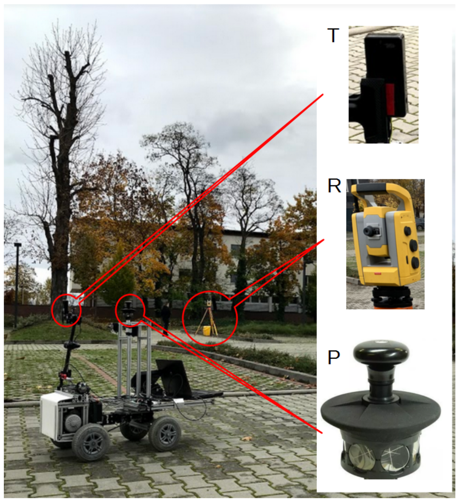
2.3. Experimental Setup
2.4. Mobile Robot
- Intel NUC—Mini PC equipped with a 4-core Intel Celeron J3455 processor and the necessary communication modules: Wi-Fi, Bluetooth, USB. The 19V supply voltage allows it to be powered from the robot’s batteries via a DC/DC step down converter,
- RbC 4242—Module designed for motor control based on microcontroler STM32F103 with ARM Cortex M3 core [64],
- FS-iA6B—RC 6 CH PPM Receiver module operating at 2.4 GHz,
- BTS7960—Motor driver module (H-bridge) 43 A, PWM capability of up to 25 kHz,
- DC motor with a power of 250 W and 24 V of supply voltage, integrated with the gear and with chain wheel on output shaft,
- AS5040—Magnetic encoder with a resolution of 1024 imp/rev.
3. Results
4. Discussion
5. Conclusions
Author Contributions
Funding
Institutional Review Board Statement
Informed Consent Statement
Data Availability Statement
Conflicts of Interest
References
- Whittaker, W. Utilization of position and orientation data for preplanning and real time autonomous vehicle navigation. In Proceedings of the 2006 IEEE/ION Position, Location, and Navigation Symposium, Coronado, CA, USA, 5 July 2006; pp. 372–377. [Google Scholar]
- Xia, Y.; Na, X.; Sun, Z.; Chen, J. Formation control and collision avoidance for multi-agent systems based on position estimation. ISA Trans. 2016, 61, 287–296. [Google Scholar] [CrossRef]
- Huang, A.S.; Bachrach, A.; Henry, P.; Krainin, M.; Maturana, D.; Fox, D.; Roy, N. Visual odometry and mapping for autonomous flight using an RGB-D camera. In Robotics Research; Springer: Berlin, Germany, 2017; pp. 235–252. [Google Scholar]
- Kagan, E.; Shvalb, N.; Ben-Gal, I. Autonomous Mobile Robots and Multi-Robot Systems: Motion-Planning, Communication, and Swarming; John Wiley & Sons: New York, NY, USA, 2019. [Google Scholar]
- Henkel, P.; Sperl, A.; Mittmann, U.; Bensch, R.; Färber, P.; Günther, C. Precise Positioning of Robots with Fusion of GNSS, INS, Odometry, Barometer, Local Positioning System and Visual Localization. In Proceedings of the 31st International Technical Meeting of The Satellite Division of the Institute of Navigation, Miami, FL, USA, 24–28 September 2018; pp. 3078–3087. [Google Scholar]
- Li, J.; Bao, H.; Han, X.; Pan, F.; Pan, W.; Zhang, F.; Wang, D. Real-time self-driving car navigation and obstacle avoidance using mobile 3D laser scanner and GNSS. Multimed. Tools Appl. 2017, 76, 23017–23039. [Google Scholar] [CrossRef]
- Karlsson, R.; Gustafsson, F. The future of automotive localization algorithms: Available, reliable, and scalable localization: Anywhere and anytime. IEEE Signal Process. Mag. 2017, 34, 60–69. [Google Scholar] [CrossRef] [Green Version]
- Perumal, L.P.N.; Doss, A.S.A. Sensor Fusion for Automotive Dead Reckoning Using GPS and IMU for Accurate Position and Velocity Estimation. In Lecture Notes in Mechanical Engineering; Springer: Singapore, 2020; pp. 83–95. [Google Scholar] [CrossRef]
- Dang, Z.; Wang, T.; Pang, F. Tightly-coupled Data Fusion of VINS and Odometer Based on Wheel Slip Estimation. In Proceedings of the 2018 IEEE International Conference on Robotics and Biomimetics (ROBIO), Kuala Lumpur, Malaysia, 12–15 December 2018; pp. 1613–1619. [Google Scholar] [CrossRef]
- Forster, C.; Carlone, L.; Dellaert, F.; Scaramuzza, D. IMU Preintegration on Manifold for Efficient Visual-Inertial Maximum-a-Posteriori Estimation. In Proceedings of the Robotics: Science and Systems, Rome, Italy, 13–17 July 2015. [Google Scholar] [CrossRef]
- Zheng, F.; Liu, Y.H. SE(2)-Constrained Visual Inertial Fusion for Ground Vehicles. IEEE Sens. J. 2018, 18, 9699–9707. [Google Scholar] [CrossRef]
- Zheng, F.; Tang, H.; Liu, Y.H. Odometry-Vision-Based Ground Vehicle Motion Estimation With SE(2)-Constrained SE(3) Poses. IEEE Trans. Cybern. 2019, 49, 2652–2663. [Google Scholar] [CrossRef] [PubMed]
- Brunker, A.; Wohlgemuth, T.; Frey, M.; Gauterin, F. Odometry 2.0: A Slip-Adaptive EIF-Based Four-Wheel-Odometry Model for Parking. IEEE Trans. Intell. Veh. 2019, 4, 114–126. [Google Scholar] [CrossRef]
- Brossard, M.; Bonnabel, S. Learning wheel odometry and IMU errors for localization. In Proceedings of the 2019 International Conference on Robotics and Automation (ICRA), Montreal, QC, Canada, 20–24 May 2019; pp. 291–297. [Google Scholar]
- Brossard, M.; Barrau, A.; Bonnabel, S. RINS-W: Robust inertial navigation system on wheels. arXiv 2019, arXiv:1903.02210. [Google Scholar]
- Brossard, M.; Barrau, A.; Bonnabel, S. AI-IMU Dead-Reckoning. IEEE Trans. Intell. Veh. 2020, 5, 585–595. [Google Scholar] [CrossRef]
- Stefaniak, P.; Gawelski, D.; Anufriiev, S.; Śliwiński, P. Road-quality classification and motion tracking with inertial sensors in the deep underground mine. In Asian Conference on Intelligent Information and Database Systems; Springer: Berlin, Germany, 2020; pp. 168–178. [Google Scholar]
- Paraszczak, J.; Gustafson, A.; Schunnesson, H. Technical and operational aspects of autonomous LHD application in metal mines. Int. J. Min. Reclam. Environ. 2015, 29, 391–403. [Google Scholar] [CrossRef]
- Gustafson, A.; Paraszczak, J.; Tuleau, J.; Schunnesson, H. Impact of technical and operational factors on effectiveness of automatic load-haul-dump machines. Min. Technol. 2017, 126, 185–190. [Google Scholar] [CrossRef]
- Kawalec, P. How Will the 4th Industrial Revolution Influences the Extraction Industry? J. Pol. Miner. Eng. Soc. 2019, 21, 327–334. [Google Scholar]
- Dyson, N. Syama’s Automation Surge. Available online: https://www.miningmagazine.com/technology-innovation/news/1387604/syama’s-automation-surge (accessed on 6 December 2020).
- Geodata. Tauros—Guidance System for Sandvik Roadheaders. Available online: http://geodata.com.hr/wp-content/uploads/2016/09/Tauros_tsm.pdf (accessed on 6 December 2020).
- Bartoszek, S. Pozycjonowanie kombajnu chodnikowego w wyrobisku korytarzowym/Positioning the roadheader in a roadway [in Polish]. Maszyny Górnicze 2016, 34, 22–35. [Google Scholar]
- Zimoz, R.; Wodecki, J.; Sobkowicz, J.H.; Wyłomanska, A.; Stefaniak, P.; Sliwinski, P.; Kaniewski, T. Mobile based vibration monitoring and its application to road quality monitoring in deep underground mine. Vibroeng. Procedia 2018, 19, 153–158. [Google Scholar] [CrossRef] [Green Version]
- Zimroz, R.; Hutter, M.; Mistry, M.; Stefaniak, P.; Walas, K.; Wodecki, J. Why Should Inspection Robots be used in Deep Underground Mines? In Proceedings of the 27th International Symposium on Mine Planning and Equipment Selection—MPES 2018; Widzyk-Capehart, E., Hekmat, A., Singhal, R., Eds.; Springer International Publishing: Cham, Switzerland, 2019; pp. 497–507. [Google Scholar]
- Szrek, J.; Wodecki, J.; Blazej, R.; Zimroz, R. An Inspection Robot for Belt Conveyor Maintenance in Underground Mine—Infrared Thermography for Overheated Idlers Detection. Appl. Sci. 2020, 10, 4984. [Google Scholar] [CrossRef]
- Su, X.; Tong, H.; Ji, P. Accelerometer-based activity recognition on smartphone. In Proceedings of the 23rd ACM International Conference on Conference on Information and Knowledge Management, Shanghai, China, 3–7 November 2014; pp. 2021–2023. [Google Scholar]
- Pires, I.M.; Garcia, N.M.; Pombo, N.; Flórez-Revuelta, F. From data acquisition to data fusion: A comprehensive review and a roadmap for the identification of activities of daily living using mobile devices. Sensors 2016, 16, 184. [Google Scholar] [CrossRef] [PubMed]
- Yean, S.; Lee, B.; Yeo, C.; Vun, C.; Oh, H. Smartphone Orientation Estimation Algorithm Combining Kalman Filter with Gradient Descent. IEEE J. Biomed. Health Inform. 2018, 22, 1421–1433. [Google Scholar] [CrossRef] [PubMed]
- Marins, J.L.; Yun, X.; Bachmann, E.R.; McGhee, R.B.; Zyda, M.J. An extended Kalman filter for quaternion-based orientation estimation using MARG sensors. In Proceedings of the 2001 IEEE/RSJ International Conference on Intelligent Robots and Systems, Expanding the Societal Role of Robotics in the the Next Millennium (Cat. No.01CH37180), Maui, HI, USA, 29 October–3 November 2001; pp. 2003–2011. [Google Scholar] [CrossRef]
- Munguía, R.; Grau, A. A practical method for implementing an attitude and heading reference system. Int. J. Adv. Robot. Syst. 2014, 11. [Google Scholar] [CrossRef] [Green Version]
- Whitaker, J.; Christensen, R.; Droge, G. Global Localization of Ground Vehicles Using Self-Describing Fiducials Coupled with IMU Data. In 2020 IEEE/ION Position, Location and Navigation Symposium (PLANS); IEEE: Piscataway, NJ, USA, 2020. [Google Scholar] [CrossRef]
- Li, X.; Wang, Y.; Khoshelham, K. A Robust and adaptive complementary Kalman filter based on Mahalanobis distance for ultra wideband/inertial measurement unit fusion positioning. Sensors 2018, 18, 3435. [Google Scholar] [CrossRef] [Green Version]
- Li, M.G.; Zhu, H.; You, S.Z.; Wang, L.; Zhang, Z.; Tang, C.Q. IMU-aided ultra-wideband based localization for coal mine robots. In Lecture Notes in Computer Science (Including Subseries Lecture Notes in Artificial Intelligence and Lecture Notes in Bioinformatics); Springer: Cham, Switzerland, 2019; Volume 11740, pp. 256–268. [Google Scholar] [CrossRef]
- Fan, Q.; Wu, H.; Hui, J.; Wu, L.; Yu, Z.; Zhou, L. Integrated Navigation Fusion Strategy of INS/UWB for Indoor Carrier Attitude Angle and Position Synchronous Tracking. Sci. World J. 2014, 2014, 215303. [Google Scholar] [CrossRef]
- Li, X.; Wang, Y. Evaluation of AHRS algorithms for Foot-Mounted Inertial-based Indoor Navigation Systems. Open Geosci. 2019, 11, 48–63. [Google Scholar] [CrossRef]
- Jauch, J.; Masino, J.; Staiger, T.; Gauterin, F. Road Grade Estimation With Vehicle-Based Inertial Measurement Unit and Orientation Filter. IEEE Sens. J. 2018, 18, 781–789. [Google Scholar] [CrossRef]
- Zhang, H.; Zhang, Z.; Gao, N.; Xiao, Y.; Meng, Z.; Li, Z. Cost-effective wearable indoor localization and motion analysis via the integration of UWB and IMU. Sensors 2020, 20, 344. [Google Scholar] [CrossRef] [PubMed] [Green Version]
- Sun, M.; Wang, Y.; Xu, S.; Cao, H.; Si, M. Indoor positioning integrating PDR/Geomagnetic positioning based on the genetic-particle filter. Appl. Sci. 2020, 10, 668. [Google Scholar] [CrossRef] [Green Version]
- Madgwick, S.; Harrison, A.; Vaidyanathan, R. Estimation of IMU and MARG orientation using a gradient descent algorithm. In Proceedings of the 2011 IEEE International Conference on Rehabilitation Robotics, Zurich, Switzerland, 29 June–1 July 2011; pp. 1–7. [Google Scholar] [CrossRef]
- Lavrinec, A.; Orozovic, O.; Williams, K.; Jones, M.; Klinzing, G.; Clark, W.; Wang, Z. Observations of dense phase pneumatic conveying using an inertial measurement unit. Powder Technol. 2019, 343, 436–444. [Google Scholar] [CrossRef]
- Musaab, A.; Sulle, B.; Minarso, A. Design of AHRS for quadrotor control using digital motion processor. J. Telecommun. Electron. Comput. Eng. 2017, 9, 77–82. [Google Scholar]
- He, B.; Wang, H.; Li, M.; Yury, K.; Shi, X. A Novel Indoor Positioning Algorithm Based on IMU. In Lecture Notes of the Institute for Computer Sciences, Social-Informatics and Telecommunications Engineering. ChinaCom 2019; Springer: Cham, Switzerland, 2009; Volume 313, pp. 168–179. [Google Scholar] [CrossRef]
- Vana, S.; Naciri, N.; Bisnath, S. Benefits of motion constraining for robust, low-cost, dual-frequency GNSS PPP + MEMS IMU navigation. In 2020 IEEE/ION Position, Location and Navigation Symposium (PLANS); IEEE: Piscataway, NJ, USA, 2020; pp. 1093–1103. [Google Scholar] [CrossRef]
- Chehri, A.; Fortier, P.; Tardif, P.M. Geolocation for UWB networks in underground mines. In Proceedings of the 2006 IEEE Annual Wireless and Microwave Technology Conference; IEEE: Piscataway, NJ, USA, 2006; pp. 1–4. [Google Scholar]
- Chehri, A.; Fortier, P.; Tardif, P.M. CTHp1-8: Measurements and modeling of line-of-sight UWB channel in underground mines. In IEEE Globecom 2006; IEEE: Piscataway, NJ, USA, 2006; pp. 1–5. [Google Scholar]
- Capraro, F.; Segura, M.; Sisterna, C. Human real time localization system in underground mines using uwb. IEEE Lat. Am. Trans. 2020, 18, 392–399. [Google Scholar] [CrossRef]
- Li, M.G.; Zhu, H.; You, S.Z.; Tang, C.Q. UWB-Based Localization System Aided with Inertial Sensor for Underground Coal Mine Applications. IEEE Sens. J. 2020, 20, 6652–6669. [Google Scholar] [CrossRef]
- DWM1001 System OverviewAnd Performance. Available online: https://www.decawave.com/wp-content/uploads/2019/05/DWM1001_System_Overview.pdf (accessed on 18 October 2020).
- Filipenko, M.; Afanasyev, I. Comparison of various slam systems for mobile robot in an indoor environment. In Proceedings of the 2018 International Conference on Intelligent Systems (IS); IEEE: Piscataway, NJ, USA, 2018; pp. 400–407. [Google Scholar]
- Yousif, K.; Bab-Hadiashar, A.; Hoseinnezhad, R. An overview to visual odometry and visual SLAM: Applications to mobile robotics. Intell. Ind. Syst. 2015, 1, 289–311. [Google Scholar] [CrossRef]
- Whelan, T.; Johannsson, H.; Kaess, M.; Leonard, J.J.; McDonald, J. Robust real-time visual odometry for dense RGB-D mapping. In Proceedings of the 2013 IEEE International Conference on Robotics and Automation; IEEE: Piscataway, NJ, USA, 2013; pp. 5724–5731. [Google Scholar]
- Pire, T.; Fischer, T.; Castro, G.; De Cristóforis, P.; Civera, J.; Berlles, J.J. S-PTAM: Stereo parallel tracking and mapping. Robot. Auton. Syst. 2017, 93, 27–42. [Google Scholar] [CrossRef] [Green Version]
- Mur-Artal, R.; Tardós, J.D. Orb-slam2: An open-source slam system for monocular, stereo, and rgb-d cameras. IEEE Trans. Robot. 2017, 33, 1255–1262. [Google Scholar] [CrossRef] [Green Version]
- Engel, J.; Schöps, T.; Cremers, D. LSD-SLAM: Large-scale direct monocular SLAM. In European Conference on Computer Vision; Springer: Berlin, Germany, 2014; pp. 834–849. [Google Scholar]
- Tateno, K.; Tombari, F.; Laina, I.; Navab, N. Cnn-slam: Real-time dense monocular slam with learned depth prediction. In Proceedings of the IEEE Conference on Computer Vision and Pattern Recognition, Honolulu, HI, USA, 21–26 July 2017; pp. 6243–6252. [Google Scholar] [CrossRef] [Green Version]
- Li, R.; Wang, S.; Long, Z.; Gu, D. Undeepvo: Monocular visual odometry through unsupervised deep learning. In Proceedings of the 2018 IEEE International Conference on Robotics and Automation (ICRA); IEEE: Piscataway, NJ, USA, 2018; pp. 7286–7291. [Google Scholar]
- Labbé, M.; Michaud, F. RTAB-Map as an open-source lidar and visual simultaneous localization and mapping library for large-scale and long-term online operation. J. Field Robot. 2019, 36, 416–446. [Google Scholar] [CrossRef]
- Yan, H.; Shan, Q.; Furukawa, Y. RIDI: Robust IMU double integration. In Proceedings of the European Conference on Computer Vision (ECCV), Munich, Germany, 8–14 September 2018; pp. 621–636. [Google Scholar]
- Derrode, S.; Li, H.; Benyoussef, L.; Pieczynski, W. Unsupervised pedestrian trajectory reconstruction from IMU sensors. In Proceedings of the TAIMA 2018: Traitement et Analyse de l’Information Méthodes et Applications, Hammamet, Tunisia, 30 April–5 May 2018. [Google Scholar]
- Schmid, L.; Salido-Monzú, D.; Wieser, A. Accuracy assessment and learned error mitigation of UWB ToF ranging. In Proceedings of the 2019 International Conference on Indoor Positioning and Indoor Navigation (IPIN); IEEE: Piscataway, NJ, USA, 2019; pp. 1–8. [Google Scholar]
- Ehrhart, M.; Lienhart, W. Object tracking with robotic total stations: Current technologies and improvements based on image data. J. Appl. Geod. 2017, 11, 131–142. [Google Scholar] [CrossRef]
- Jolly, K.; Kumar, R.S.; Vijayakumar, R. A Bezier curve based path planning in a multi-agent robot soccer system without violating the acceleration limits. Robot. Auton. Syst. 2009, 57, 23–33. [Google Scholar] [CrossRef]
- Module for Motor Control. Available online: http://progresja-org.com (accessed on 15 November 2020).
- Nguyen, T.M.; Zaini, A.; Guo, K.; Xie, L. An Ultra-Wideband-based Multi-UAV Localization System in GPS-Denied Environments. In International Micro Air Vehicle Competition and Conference 2016; SAGE: Beijing, China, 2016; pp. 56–61. [Google Scholar]


| Mean Robot Velocity [m/s] | Mean Absolute Location Residual [m] | Max Absolute Location Residual [m] |
|---|---|---|
| 0.34 | 0.129 | 0.741 |
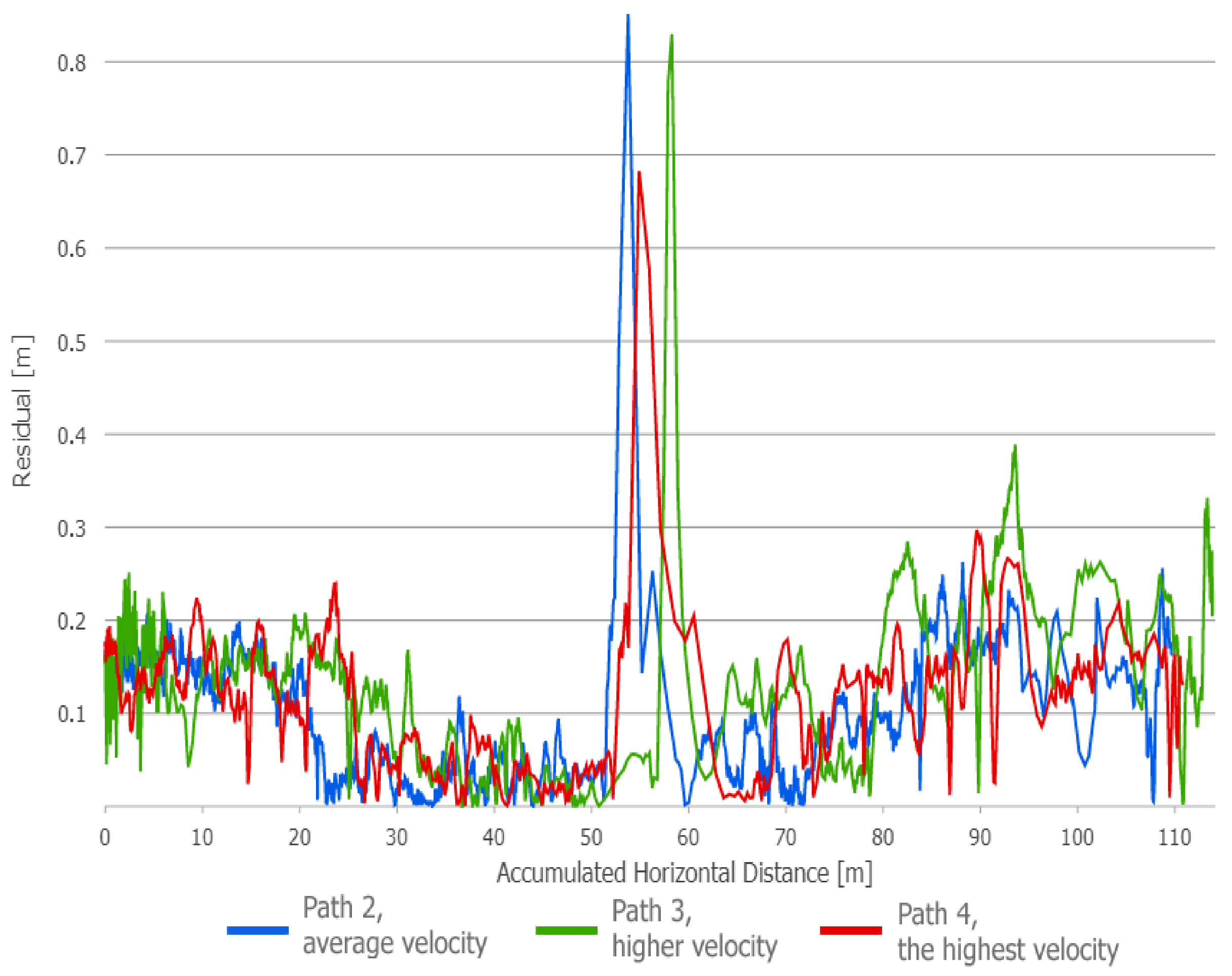
| Path Number | Mean Robot Velocity [m/s] | Mean Absolute Location Residual [m] | Max Absolute Location Residual [m] |
|---|---|---|---|
| 2 | 0.51 | 0.105 | 0.851 |
| 3 | 0.95 | 0.141 | 0.830 |
| 4 | 1.14 | 0.118 | 0.682 |
Publisher’s Note: MDPI stays neutral with regard to jurisdictional claims in published maps and institutional affiliations. |
© 2020 by the authors. Licensee MDPI, Basel, Switzerland. This article is an open access article distributed under the terms and conditions of the Creative Commons Attribution (CC BY) license (http://creativecommons.org/licenses/by/4.0/).
Share and Cite
Szrek, J.; Trybała, P.; Góralczyk, M.; Michalak, A.; Ziętek, B.; Zimroz, R. Accuracy Evaluation of Selected Mobile Inspection Robot Localization Techniques in a GNSS-Denied Environment. Sensors 2021, 21, 141. https://doi.org/10.3390/s21010141
Szrek J, Trybała P, Góralczyk M, Michalak A, Ziętek B, Zimroz R. Accuracy Evaluation of Selected Mobile Inspection Robot Localization Techniques in a GNSS-Denied Environment. Sensors. 2021; 21(1):141. https://doi.org/10.3390/s21010141
Chicago/Turabian StyleSzrek, Jarosław, Paweł Trybała, Mateusz Góralczyk, Anna Michalak, Bartłomiej Ziętek, and Radosław Zimroz. 2021. "Accuracy Evaluation of Selected Mobile Inspection Robot Localization Techniques in a GNSS-Denied Environment" Sensors 21, no. 1: 141. https://doi.org/10.3390/s21010141