Theoretical and Experimental Analysis of Dynamic Characteristics for a Valve Train System

1
Hunan Provincial Key Laboratory of Intelligent Manufacturing Technology for High-Performance Mechanical Equipment, Changsha University of Science and Technology, Changsha 410114, China
2
State Key Laboratory of Advanced Design and Manufacturing for Vehicle Body, Hunan University, Changsha 410082, China
*
Author to whom correspondence should be addressed.
Sensors 2021, 21(19), 6328; https://doi.org/10.3390/s21196328
Submission received: 28 July 2021
/
Revised: 31 August 2021
/
Accepted: 18 September 2021
/
Published: 22 September 2021
(This article belongs to the Section Physical Sensors)
Abstract
:The valve train is one of the main sources of engine vibration, and its dynamic performance is crucial for output power and fuel consumption. The flexibilities of slender bars and beams should be emphasised in the design of valve trains to develop high-power and high-speed engines with industrial applications. A flexible dynamic model of a valve train system is proposed. In the proposed model, the components, except the cam and gear bodies, are modelled as flexible bodies with multidirectional deformations. The gyroscopic effects of the camshaft, cams and gear discs are also considered to predict dynamic responses at high speeds accurately. Gear meshing, the friction of the cam–tappet pair, the centrifugal force of the cams and valve clearance are also considered. Experiments on housing vibration and pushrod stress are conducted to validate the proposed model. Results show that the proposed model can predict the dynamic stress of the flexible components well and predict the trend shown by the housing vibration. The proposed model shows that excessive cam rotation speed and valve clearance will cause intense bounce and jump phenomena. The proposed model can be an important reference for designing engine work speed, adjusting valve clearance and improving component durability.
1. Introduction
The valve train system is one of the most important engine parts. It consists of a series of components that are prone to deformation. The dynamics and kinematics performances of these components affect engine performance indices, including output power, economy, reliability, noise and vibration [1,2], especially at high cam rotation speeds. Therefore, developing a dynamic model that analyses the kinematics and dynamics performances of the valve strain system accurately is important.
Previous studies have developed different dynamic models of the valve train system. Teodorescu et al. [3,4] proposed a dynamic valve train model with two equivalent masses by using the lumped parameter method. Nevertheless, these studies disregard contact deformation between components and the elastic deformation of slender components. A rigid multibody dynamic model of the valve trains or cam mechanisms that considers each component as a rigid [5,6,7,8,9], and many researchers have used this model to optimize the cam profile [10,11]. A multiple degree-of-freedom (DOF) model has been established by dividing the valve spring into multimass elements [12,13]. The distributed parameter model of the valve spring has better accuracy than the lumped parameter model but continues to neglect the elastic deformation of slender components. Jelenschi et al. [7] proposed an improved model that accounts for the flexibility of components. Guo et al. [14] and Qin et al. [15] developed the rigid-flexible coupled dynamic model of the valve train system.
Numerous researchers have applied the flexible dynamics theory to analyse the dynamic performance of mechanical systems. An increasing number of factors are considered in the flexible dynamic model. These factors include the clearance of the follower guide [16] and the friction of the cam–tappet pair [17]. Nevertheless, previous studies have ignored the effect of camshaft dynamics. Rivola et al. [18] developed a dynamic camshaft model by applying the finite element method. The flexibility of the camshaft drastically affects the dynamic behaviour of the valve train [19,20,21]. The gyroscopic effect of the rotor disc [22], the presence of eccentricity [23] and the multidirection vibrations of the camshaft [17,24] have also been considered in the dynamic models of valve trains.
Jump and bounce phenomena [7,12,14,15,24] may occur in the valve train system with the increase in cam speed. Impact forces in the presence of these phenomena cause non-negligible deformation and weaken the dynamic performance of the valve train system. The gyroscopic effect and clearance impact have considerable influence on the dynamic response of the valve train at high speeds. However, previous studies have ignored these two factors. Therefore, a flexible dynamic model with the gyroscopic effect and valve clearance impact was developed in this work. The camshaft and rocker arm were modelled as flexible bodies that are based on Timoshenko beam elements, whereas the slender pushrod, valve and tappet were modelled by using bar elements. In addition, the gear meshing, the friction between the cam and tappet and the centrifugal force of the cams were considered. Then, experiments on the housing vibration and pushrod stress were conducted to validate the proposed model and the effects of the cam speed and valve clearance on jump and bounce phenomena were investigated.
2. Dynamic Model
A valve train system includes inlet and outlet air valve trains and a camshaft. Given that the structure of the outlet air valve train is the same as that of the inlet air valve train, the outlet air valve train is removed to simplify the dynamic model in this study. The flexible model of the valve train system is presented in Figure 1. The tappet, pushrod and valve are considered as bar elements, whereas the camshaft and rocker arm are divided into the resultant elements of a Timoshenko beam element and bar element. In this study, the gear disc, inlet and outlet air cams, which are mounted on the camshaft, are considered as rigid bodies. The valve spring and the contact deformation between two components are simplified as linear spring-damper elements.
The driving shaft and camshaft are divided into seven and eight elements, respectively, and the inlet air valve train is separated into seven elements. Consequently, the dynamic model includes 28 nodes and 22 elements. The structural parameters of these elements are listed in Table 1.
2.1. Flexible Shaft Element
In this work, Timoshenko beam theory is used to establish the flexible shaft element. Given that the camshaft is driven by a helical gear pair, the torsional and axial deformations are included. Therefore, dynamic equations of the resultant element are derived by combining a Timoshenko beam with torsional and bar elements. Each element has 2 nodes, and each node has 6 DOF. The displacement vector of the shaft element is expressed as
where i is the node i (i = 1, 2,⋯, 17) on the camshaft, and the kinetic energy and potential energy of the shaft element are expressed as
where the displacement vector of an arbitrary point on the shaft element can be represented as , and the shape function N can be found in a previous article [25,26]. Besides, (c = x, y, z) represents the derivative of with respect to time, however, (c = x, y, z) represents the derivative of with respect to z coordinate.
The dynamic equations of the flexible shaft element are derived by using the Lagrange equation, and the matrix form is represented as
2.2. Rotor Disc and Supporting Stiffness
The rotor discs on the camshaft include the inlet and outlet air cams and the gear body. Six DOF are taken into account and can be represented as
where i (i = 11, 13, 15) represents the node on which the rotor discs are mounted. The kinetic energy of these discs is represented as
The dynamics equations of the rotor disc are derived by using the Lagrange equation and can be written as
Mid and Gid are the mass and gyroscopic matrices, respectively, and are expressed as follows:
The valve train system has four ball bearings and a joint after removing the outlet air valve train. Bearings #1, #2, #3 and #4 support the camshaft and are installed on nodes 1, 8, 9 and 17, respectively. Joint supports the rocker arm and is mounted on node 24. The camshaft and rocker arm rotate around the z-axis. Supporting stiffness Kb and damping Cb are represented as [27]
where radial stiffness, tilting stiffness, axial stiffness, radial damping, tilting damping and axial damping are represented as kii(i = x, y), kθiθi, kzz, cii, cθiθi and czz, respectively. The values of these parameters are shown in Table 2. Note that the values of the stiffness (kzi, kiz, kzθi, kxy and kyx) are small in ball bearings. Thus, the values of these parameters are set as 0.
2.3. Gear Meshing Formulations
The camshaft is driven through a helical gear pair. The driving pinion is mounted on node 3, and the driven gear is fixed on node 11. The displacement vector of the helical gear pair is presented as
Taking static transmission error into account, the contact deformation between the meshing gears can be represented as
where este(t) can be defined in accordance with a previous work [28], and vector Vg can be written as
The mesh force of the gear pair with backlash can be represented as
where the backlash function can be represented as follows:
Then, the dynamic equation of the meshing gear pair is expressed in the following matrix form:
where the mass matrix Mg, damping matrix Cg and stiffness matrix Kg are written as
2.4. Inlet Air Valve Train
The inlet air valve train is divided into seven elements. The tappet, pushrod and valve are meshed as bar elements, and the rocker arm is constructed as a 2D Timoshenko beam element. The dynamic equations of the bar element and 2D beam element can be obtained by extracting the corresponding DOF of the vector . The bar element with 2 DOF can be represented as:
where i (i = 18, 19, 22, 26, 27, 28) is the node number. Six DOF on the rocker arm element are considered and are represented as
where i (i = 23, 24, 25) is the node number on the rocker arm element.
2.5. Contact Formula of the Cam–Tappet Pair with Eccentricity
The camshaft system drives the inlet air train system through the cam-tappet pair. The friction and the centrifugal force of the cam-tappet pair are taken into account. Accoring to Figure 2, e is the eccentric distance, and φ is the phase angle of the cam. The dynamic contact force Fc and deformation δc can be expressed as:
where kc and cc are obtained in our previous work [30]. γc is the function that determines whether the cam and tappet are in contact. qc is the vector that includes 6 DOFs of node 13 and the axial displacement of node 18. V is the vector that determines which DOF in qc participates in the calculation of δc. γc, qc and V are written as
The matrix form of the dynamics equations of the cam-tappet pair is expressed as
In Equation (19), mass matrix Mc, damping matrix Cc, stiffness matrix Kc and force matrix Fc are written as
where Vf, fc and φ are written as
In Equation (34), the friction coefficient μ is predicted on the basis of elastohydrodynamic lubrication theory. The initial phase angle is set as 0 in this work.
2.6. Dynamic Equations of the Valve Train System
The overall system equations of the valve train system can be obtained by combining the mass, damping, gyroscopic and stiffness matrices of every node, and the matrix form of overall system equations is expressed as:
where M, C, G and K are the overall mass, damping, gyroscopic and stiffness matrices, respectively. F is the overall force matrix, and q is the vector of the overall DOF.
3. Experimental Verification and Discussion
Housing vibration and pushrod stress were measured by using a test rig of the valve train system. In Figure 3, the camshaft of the valve train system was driven by the servo motor with synchronous belt transmission, and the rotation speed of the camshaft was controlled by the motor. The piston, crank shaft and connecting rod affect housing vibration. Thus, these components were removed from the test rig. The outlet train was also removed from the test rig given that this work only analyses the dynamic behaviours of the inlet air valve train and camshaft.
Sensor #1 and Sensor #2 are two triaxial acceleration sensors. Their positions are illustrated in Figure 3. Sensor #1 was utilised to measure the housing acceleration near the joint. Sensor #2 was also used to measure the three-directional acceleration of the housing. However, the three directions did not correspond with the three directions of the global coordinate system (Figure 1), and some processing errors were generated during coordinate transformation processing. Therefore, the test data from sensor #2 were not used in this study. The sensitivity of acceleration sensor is 96.3 mV/g, and the measuring range is from −10 g to 10 g, where g is the acceleration of gravity. The internal excitation current source is used in acceleration, and the excitation current is 4 mA. The sampling frequency of acceleration measurement is set to 4096 Hz.
A full-bridge converter comprising four strain gauges mounted on the pushrod was utilised to measure pushrod stress. The installation positions of the four strain gauges have been previously described [31]. The strain gauge factor is 1.76, and the strain gauge resistance is 120 ± 3 Ω. Before installation, the real resistances of all gauges are measured using a digital multi-meter and is inputted in the LabVIEW system. The excitation voltage is set to 2.5 V and the sampling frequency of strain measurement is 10 kHz. Note that the initial strain of the four strain gauges must be balanced before measurement.
3.1. Housing Vibration
The vibration of the valve train system is transmitted to the housing through the bearings and joint. Housing vibration was evaluated by using the root-mean-square (RMS) of acceleration during many periods. The test data of Sensor #1 were obtained at the cam rotation speed of 300–2000 rpm to verify the predicted acceleration on node 24. The results for the comparison between the RMS values of the predicted and measured accelerations are illustrated in Figure 4, where the moving average method is applied to eliminate the white noise of the measured vibration signals.
As shown in Figure 4a, xrms is the RMS of the acceleration along the x direction. The trend shown by the predicted vibration is the same as that shown by the measured vibration when the cam rotation speed ranges from 300 rpm to 1450 rpm. In detail, the two curves present the same five vibration peaks at the corresponding speeds of 500, 750, 900, 1050 and 1300 rpm. A sharp upward trend appears in the measured curve, whereas the predicted curve presents a different trend when the speed exceeds 1450 rpm. The predicted vibration near 1300 rpm is higher than the measured vibration. This result may be attributed to the constant empirical damping used in this work given that the damping of the valve train system is difficult to predict accurately.
In Figure 4b, yrms represents the RMS of the acceleration along the y direction. Overall, the measured curve shows a gradual upward trend. A large, distinct vibration peak is generated at the speed of 500 rpm, and the vibration increases sharply at 1900 rpm to 2000 rpm. The predicted curve also presents a slow upward trend and a vibration peak near the speed of 500 rpm. By contrast, the predicted curve exhibits additional vibration peaks at the speed of 1200 and 1300 rpm. The amplitudes of the two curves show some differences because the predicted vibration represents the RMS of the acceleration on node 24, whereas the measured vibration represents the RMS of the acceleration on the engine housing (Figure 3).
Figure 5 illustrates the measured and predicted accelerations at different rotation speed. The acceleration becomes large with an increase in rotation speeds. Although the bars do not move during the dwell phase, the measured accelerations also have fluctuations. These fluctuations are caused by the synchronous belt and gear transmission. The predicted values are the acceleration on node 24, which does not include the synchronous belt and gear vibration. Therefore, there is no fluctuation in the curves of the predicted acceleration during the dwell phase. When the cam begins to enter or exit the working phase, two peaks appear in the curves of the acceleration. The first peak is caused by the valve impact due to the valve clearance, and the valve impact can even generate jump phenomenon of the valve. The second peak is induced by the repeated pulling and pressing of the valve spring, which causes the bounce phenomenon of the valve. The jump and bounce phenomena will be discussed in detail in the following section.
3.2. Pushrod Stress
The proposed model can be used to predict the dynamic stress of the components in the valve train system, and pushrod stress can be predicted by . Figure 6 shows the comparison results of the predicted and measured pushrod stresses at the cam rotation speeds of 600, 900, 1200 and 1800 rpm.
Positive and negative values indicate that the pushrod is stretched and compressed, respectively. During the working phase, the predicted pushrod stress first increases and then decreases at the speed of 600 rpm (Figure 6a). In contrast to the predicted results, a peak appears at approximately 235° in the measured curve at 600 rpm. As shown in Figure 6b–d, two peaks appear simultaneously in the predicted and measured curves at approximately 130° and 235°. This is because the dynamic effect on contact force and elastic deformation is considered in this work. The cam curvatures at these two positions change significantly and cause two large accelerations, which can be seen in [31]. The acceleration and contact force become large with increase in cam rotation speeds, and the contact force at these two positions will even exceed the contact force at 180°. Therefore, the stresses at these two positions increase with the increment in cam rotation speed and even exceed the stress at 180°. Slight differences exist between the predicted and the measured curve, but the two curves follow similar trends during the working phase.
The value of the predicted stress is approximately 0 during the dwell phase at four different cam rotation speeds. However, although the measured data have been processed by using the time-domain synchronous averaging method, large peaks appear in the measured curves, and the tensile stress also appears during the dwell phase. In fact, the pushrod only bears pressure. The elastic compression of the pushrod releases rapidly and results in a transitory stretch, thereby causing the tensile stress. However, the predicted model does not yet take this into account, which causes the existence of differences between the predicted and measured stresses.
3.3. Bounce and Jump
The dynamics and kinematics responses of the valve have drastic effects on the inlet and exhaust of the valve trains. The occurrence of abnormal phenomena, such as valve bounce and jump, with the increase in cam rotation speed will reduce the output power of the engine, shorten the service life of the valve spring seat and increase vibration and noise. Therefore, valve lift curves at different cam rotation speeds are predicted by using the proposed model and are compared with the theoretical lift curve to analyse the valve bounce and jump phenomena wherein the theoretical cam lift is obtained by the geometry.
Figure 7 shows the bounce and jump phenomena that occur at different cam rotation speeds when the valve clearance is set as 0.15 mm. Valve bounce is a phenomenon wherein the valve repeatedly impacts the valve seating. Valve jump is a phenomenon wherein the excessive inertial force of the valve results in the separation of the valve and rocker arm. In theory, the valve impact during the rise phase can cause the jump phenomenon, but the inertial of the valve is the dominant factor for this valve train. As shown in Figure 7a, valve bounce and slight bounce do not occur when the cam rotation speed is lower than 3400 rpm. However, intense bounce occurs when the cam rotation speed reaches 3500 rpm. In addition, the jump and bounce are also closely related to the performance parameters of the valve spring.
In general, the dynamic valve lift predicted by the flexible model should be lower than the theoretical dynamic valve lift because of elastic deformation (at 300 and 1000 rpm in Figure 7b). Valve jump occurs when the cam rotation speed is increased to 3500 rpm because of the separation between the valve and rocker arm. Slight jump occurs when the cam rotation speed is in the range of 3500–3700 rpm. Intense jump occurs when the cam rotation speed exceeds 3800 rpm. Bounce and jump phenomena at different cam rotation speeds are listed in Table 4.
As illustrated in Table 4, the cam rotation speed has a drastic effect on valve bounce and jump. Only slight bounce with negligible effects on dynamic behaviour is observed at the speed of 3400 rpm. Slight jump and intense bounce are observed at the speed of 3500 rpm. Jump sharply increases the degree of valve bounce by introducing large impact forces between the valve and seat at seating. Moreover, it delays valve closing. Therefore, jump will increase vibration; reduce output power and damage the valve, spring and seat. The predicted results indicate that the working speed of the valve train system should not exceed 3400 rpm.
The generation of impact force between the rocker arm and valve given the existence of valve clearance aggravates the degree of bounce and jump. The valve lift curves at different clearances are predicted at the cam rotation speed of 3400 rpm to investigate the effect of valve clearance on bounce and jump.
Figure 8 illustrates the degree of valve bounce at different clearances. Bouncing degrees show slight differences when valve clearance < 0.55 mm and increase when valve clearance is increased to 0.55 mm. The increase in valve clearance to a certain degree will cause excessive bounce. However, bounce is attenuated when the valve clearance exceeds 0.7 mm. Given that the maximum compression of the valve spring is reduced with the increase in clearance, the effect of reduced spring force on the bounce exceeds that of impact force caused by clearance. This effect weakens bounce.
The degree of jump at different clearances is shown in Figure 9. Intense jump occurs when valve clearance exceeds 0.55 mm, and the degree of jump is aggravated with the increase in the valve clearance. The contact and separation states between the cam, tappet, pushrod, rocker arm and valve are included in the proposed model. Impact force is closely related to impact velocity, as shown in Equations (23)–(25). The impact velocity increases when crossing a large clearance, and the valve spring is difficult to restrain separation between two parts. The theoretic valve lift is larger than the predicted one with a small clearance due to the elastic deformation. Although there is also the clearance and elastic deformation, the theoretic valve lift is smaller than the predicted one with a large clearance because of the existence of separation. Therefore, the excessive valve clearance will cause intense jump due to the separation.
4. Conclusions
A flexible dynamic model with the gyroscopic effect and valve clearance impact was developed in this work. The camshaft and rocker arm were modelled as flexible bodies that were based on Timoshenko beam elements, whereas the slender pushrod, valve and tappet were modelled by using bar elements. This model accounted for the multidirectional deformation of the rocker arm; the torsion-bending coupling vibration of the camshaft; the gyroscopic effect of the camshaft, cam and gear discs; gear meshing; the friction between the cam and tappet and the centrifugal force of the cams. Then, the proposed model was verified through experiments on housing vibration and pushrod stress. Finally, the bounce and jump phenomena were predicted by the proposed model, and the effects of the cam speed and valve clearance on the severity of jump and bounce were investigated.
(1) The comparative analysis of the measured and predicted housing vibrations shows that the proposed model can predict the vibration trend. The differences between the measured and predicted results may be attributed to the difference between the measured position and the predicted node. In future studies, housing will be meshed as a flexible component through the finite element method, and housing vibration at the same measurement position will be predicted.
(2) Given that the components were modelled as flexible bodies, the proposed model can be used to predict inner stress. Some small differences existed between the amplitudes of the measured stress and predicted pushrod stresses. The comparative analysis indicates that the proposed model can predict the dynamic stress of the flexible components well. In addition, the increment in impact force and inertial force at approximately 130°and 230° with the increase in cam speed caused two peaks in the pushrod stress.
(3) The cam rotation speed and valve clearance had a considerable effect on the jump and bounce phenomena of the valve train. Intense jump and bounce phenomena occurred when the cam speed exceeded 3500 rpm. Excessive valve clearance resulted in intense jump and bounce even when the valve train worked at low speed. In addition, jumping caused intense bounce because of the separation of the cam and tappet.
The proposed model can be applied to predict the dynamic performance of valve trains. The analytical results are beneficial for adjusting valve clearance, designing cam profiles, improving component durability and reducing experimental costs. The accuracy of the prediction results can be improved by considering manufacturing and assembly errors in the proposed model. This approach will be studied in future works.
Author Contributions
Conceptualization, B.H. and L.Y.; methodology, B.H. and Y.L.; software, B.H. and Y.L.; validation, B.H. and Y.L.; formal analysis, B.H. and Y.L.; investigation, B.H. and Y.L.; resources, B.H. and L.Y.; data curation, B.H.; Writing—Original Draft Preparation, B.H. and Y.L.; Writing—Review and Editing, B.H. and L.Y.; visualization, B.H.; supervision, and L.Y.; project administration, B.H. and L.Y.; funding acquisition, B.H. and L.Y. All authors have read and agreed to the published version of the manuscript.
Funding
This research is funded by the National Natural Science Foundation of China (Grant no. 52005051 and 52175003) and Natural Science Foundation of Hunan Province (Grant no. 2021JJ40580 and 2021JJ30726).
Institutional Review Board Statement
Not applicable.
Informed Consent Statement
Not applicable.
Data Availability Statement
All experimental and predicted data will be made available on request to the correspondent author’s email with appropriate justification.
Conflicts of Interest
The authors declare no conflict of interest.
Nomenclature
| cm | Mesh damping of the gear pair |
| cc | Contact damping of the cam-tappet pair |
| este(t) | Static transmission error |
| fc | Cam centrifugal force |
| km | Mesh stiffness of the gear pair |
| kc | Contact stiffness of the cam-tappet pair |
| mc | The mass of the cam |
| mp | The mass of the pinion |
| mg | The mass of the gear |
| md | The mass of the disc |
| mi | The mass of ith element |
| q | Displacement vector of the overall DOF |
| qis | Displacement vector of the shaft element |
| qs | Displacement vector of arbitrary point on the shaft |
| qg | Displacement vector of the meshing gear pair |
| qid | Displacement vector of node i on the rotor disc |
| qik | Displacement vector of node i on the beam element |
| qib | Displacement vector of node i on the bar element |
| qc | Displacement vector of the cam-tappet pair |
| rbp | The base radius of the pinion |
| rbg | The base radius of the gear |
| ui | The ith DOF of the dynamic model |
| A | The cross-sectional area of the shaft element |
| B | The half of gear backlash |
| Cb | Damping matrix of the bearing |
| Cg | Damping matrix of the gear pair |
| Cc | Damping matrix of the cam-tappet pair |
| C | Overall damping matrix of the dynamic model |
| E | Young’s modulus of the material |
| Fis | Force matrix of the shaft element |
| Fid | Force matrix of the rotor disc |
| Fc | Contact force of the cam-tappet pair |
| Fc | Force matrix of the cam-tappet pair |
| F | Overall force matrix of the dynamic model |
| G | Overall gyroscopic matrix of the dynamic model |
| Gis | Gyroscopic matrix of the shaft element |
| Gid | Gyroscopic matrix of the rotor disc |
| JDs | Diameter mass moments of inertia of the shaft element |
| JPs | Polar mass moments of inertia of the shaft element |
| JDd | The moment of inertia about a diameter of the disc |
| JPd | The polar moment of inertia of the disc |
| JPp | The polar moment of inertia of the pinion |
| JDp | The moment of inertia about a diameter of the pinion |
| JDg | The moment of inertia about a diameter of the gear |
| JPg | The polar moment of inertia of the gear |
| JPc | The polar moment of inertia of the cam |
| JDc | The moment of inertia about a diameter of the cam |
| Kis | The stiffness matric of the shaft element |
| Kb | The stiffness matric of the ball bearing |
| Kg | Stiffness matrix of the gear pair |
| Kc | Stiffness matrix of the cam-tappet pair |
| K | Overall stiffness matrix of the dynamic model |
| Li | The length of ith element |
| Mis | Mass matrix of the shaft element |
| Mid | Mass matrix of the rotor disc |
| Mg | Mass matrix of the gear pair |
| Mc | Mass matrix of the cam-tappet contact |
| M | Overall mass matrix of the dynamic model |
| N | Shape function of the shaft element |
| αt | Transverse pressure angle |
| βb | Base helix angle |
| δm | Dynamic displacement of the meshing gear pair |
| δc | Dynamic deformation of the cam-tappet pair |
| μ | Friction coefficient of the cam-tappet pair |
| ρ | Material density of the shaft element |
| φ | Phase angle of the cam |
| φ0 | Initial phase angle of the cam |
| Ω | Spin speed of the shaft |
References
- Guo, J.; Cao, Y.; Zhang, W.; Zhang, X. Analysis of Engine Vibration and Noise Induced by a Valve Train Element Combined with the Dynamic Behaviors. J. Eng. Gas Turbines Power 2016, 138, 092806. [Google Scholar] [CrossRef]
- Hu, B.; Zhou, C.; Wang, H.; Yin, L. Prediction and validation of dynamic characteristics of a valve train system with flexible components and gyroscopic effect. Mech. Mach. Theory 2021, 157, 104222. [Google Scholar] [CrossRef]
- Teodorescu, M.; Votsios, V.; Rahnejat, H.; Taraza, D. Jounce and impact in cam-tappet conjunction induced by the elastodynamics of valve train system. Meccanica 2006, 41, 157–171. [Google Scholar] [CrossRef]
- Teodorescu, M.; Rahnejat, H. Mathematical modelling of layered contact mechanics of cam–tappet conjunction. Appl. Math. Model. 2007, 31, 2610–2627. [Google Scholar] [CrossRef]
- Paranjpe, R. Dynamic analysis of a valve spring with a coulomb-friction damper. J. Mech. Des. 1990, 112, 509–513. [Google Scholar] [CrossRef]
- Xuesong, M.; Youbai, X. A numerical analysis of the nonsteady EHL process in high-speed rotating engine cam/tappet pairs. J. Tribol. 1996, 118, 637–643. [Google Scholar] [CrossRef]
- Jelenschi, L.; Cofaru, C.; Sandu, G. Analyzing a direct acting valve train system. In 3rd WSEAS International Conference; MEQAPS: Sozopol, Bulgaria, 2011; pp. 11–13. [Google Scholar]
- Satyanarayana, M.; Dukkipati, R.V. Dynamic Response of Cam-Follower Mechanism; SAE Technical Paper No. 2009-01-1416; SAE: Warrendale, PA, USA, 2009. [Google Scholar]
- Huang, L.; Yin, L.; Liu, B.; Yang, Y. Design and Error Evaluation of Planar 2DOF Remote Center of Motion Mechanisms With Cable Transmissions. J. Mech. Des. 2021, 143, 013301. [Google Scholar] [CrossRef]
- Yu, J.; Luo, H.; Hu, J.; Nguyen, T.V.; Lu, Y. Reconstruction of high-speed cam curve based on high-order differential interpolation and shape adjustment. Appl. Math. Comput. 2019, 356, 272–281. [Google Scholar] [CrossRef]
- Luo, H.; Yu, J.; Li, L.; Huang, K.; Zhang, Y.; Liao, K. A novel framework for high-speed cam curve synthesis: Piecewise high-order interpolation, pointwise scaling and piecewise modulation. Mech. Mach. Theory 2021, 167. [Google Scholar] [CrossRef]
- Frendo, F.; Vitale, E.; Carmignani, L.; Gagliardi, D.; Matteucci, L. Development of a Lumped-Parameter Model for the Dynamic Analysis of Valve Train Systems; SAE Technical Paper NO. 2004-32-0051; SAE: Warrendale, PA, USA, 2004. [Google Scholar]
- Lee, J.; Patterson, D. Nonlinear valve train dynamics simulation with a distributed parameter model of valve springs. J. Eng. Gas Turbines Power 1997, 119, 692–698. [Google Scholar] [CrossRef]
- Guo, J.; Zhang, W.; Zou, D. Development and validation of a rigid–flexible coupled dynamic valve-train model. Proc. Inst. Mech. Eng. Part D J. Automob. Eng. 2012, 226, 94–111. [Google Scholar] [CrossRef]
- Qin, W.; Shen, J. Multibody System Dynamics Modelling and Characteristic Prediction for One Diesel’s Valve Train. In Proceedings of the 2009 Second International Conference on Information and Computing Science, Manchester, UK, 21–22 May 2009; IEEE: Manhattan, NY, USA, 2009; pp. 45–48. [Google Scholar]
- Yousuf, L.S. Experimental and simulation investigation of nonlinear dynamic behavior of a polydyne cam and roller follower mechanism. Mech. Syst. Signal Process. 2019, 116, 293–309. [Google Scholar] [CrossRef]
- Siczek, K.; Stefański, A. Analysis of dynamics and friction resistance in the cam-tappet system. J. Theor. Appl. Mech. 2019, 57, 273–286. [Google Scholar] [CrossRef]
- Rivola, A.; Troncossi, M.; Dalpiaz, G.; Carlini, A. Elastodynamic analysis of the desmodromic valve train of a racing motorbike engine by means of a combined lumped/finite element model. Mech. Syst. Signal Process. 2007, 21, 735–760. [Google Scholar] [CrossRef]
- Koster, M. Effect of flexibility of driving shaft on the dynamic behavior of a cam mechanism. J. Eng. Ind. 1975, 97, 595–602. [Google Scholar] [CrossRef]
- Kushwaha, M.; Rahnejat, H.; Jin, Z. Valve-train dynamics: A simplified tribo-elasto-multi-body analysis. Proc. Inst. Mech. Eng. Part K J. Multi-Body Dyn. 2000, 214, 95–110. [Google Scholar] [CrossRef] [Green Version]
- Teodorescu, M.; Kushwaha, M.; Rahnejat, H.; Taraza, D. Elastodynamic transient analysis of a four-cylinder valvetrain system with camshaft flexibility. Proc. Inst. Mech. Eng. Part K J. Multi-Body Dyn. 2005, 219, 13–25. [Google Scholar] [CrossRef] [Green Version]
- Carlini, A.; Rivola, A. A nonlinear elastodynamic model of a camshaft supported by journal bearings. In Proceedings of the AIMETA’03–16th AIMETA Congress of Theoretical and Applied Mechanics, Ferrara, Italy, 9–12 September 2003; pp. 9–12. [Google Scholar]
- Tounsi, M.; Chaari, F.; Walha, L.; Fakhfakh, T.; Haddar, M. Dynamic behavior of a valve train system in presence of camshaft errors. Wseas Trans. Theor. Mech. 2011, 1, 17–26. [Google Scholar]
- Guo, J.; Zhang, W.; Zou, D. Investigation of dynamic characteristics of a valve train system. Mech. Mach. Theory 2011, 46, 1950–1969. [Google Scholar] [CrossRef]
- Nelson, H. A finite rotating shaft element using Timoshenko beam theory. J. Mech. Des. 1980, 102, 793–803. [Google Scholar] [CrossRef]
- Hu, B.; Zhou, C.; Wang, H.; Chen, S. Nonlinear tribo-dynamic model and experimental verification of a spur gear drive under loss-of-lubrication condition. Mech. Syst. Signal Process. 2021, 153, 107509. [Google Scholar] [CrossRef]
- Chen, S.; Tang, J.; Li, Y.; Hu, Z. Rotordynamics analysis of a double-helical gear transmission system. Meccanica 2016, 51, 251–268. [Google Scholar] [CrossRef]
- Hu, Z.; Tang, J.; Zhong, J.; Chen, S.; Yan, H. Effects of tooth profile modification on dynamic responses of a high speed gear-rotor-bearing system. Mech. Syst. Signal Process. 2016, 76, 294–318. [Google Scholar] [CrossRef]
- Wan, Z.; Cao, H.; Zi, Y.; He, W.; Chen, Y. Mesh stiffness calculation using an accumulated integral potential energy method and dynamic analysis of helical gears. Mech. Mach. Theory 2015, 92, 447–463. [Google Scholar] [CrossRef]
- Hu, B.; Zhou, C.; Chen, S. Elastic dynamics modelling and analysis for a valve train including oil film stiffness and dry contact stiffness. Mech. Mach. Theory 2019, 131, 33–47. [Google Scholar] [CrossRef]
- Zhou, C.; Hu, B.; Chen, S.; He, L. An enhanced flexible dynamic model and experimental verification for a valve train with clearance and multi-directional deformations. J. Sound Vib. 2017, 410, 249–268. [Google Scholar] [CrossRef]
Figure 1.
Flexible dynamics model of the valve train system.

Figure 2.
Schematic of the cam–tappet pair.
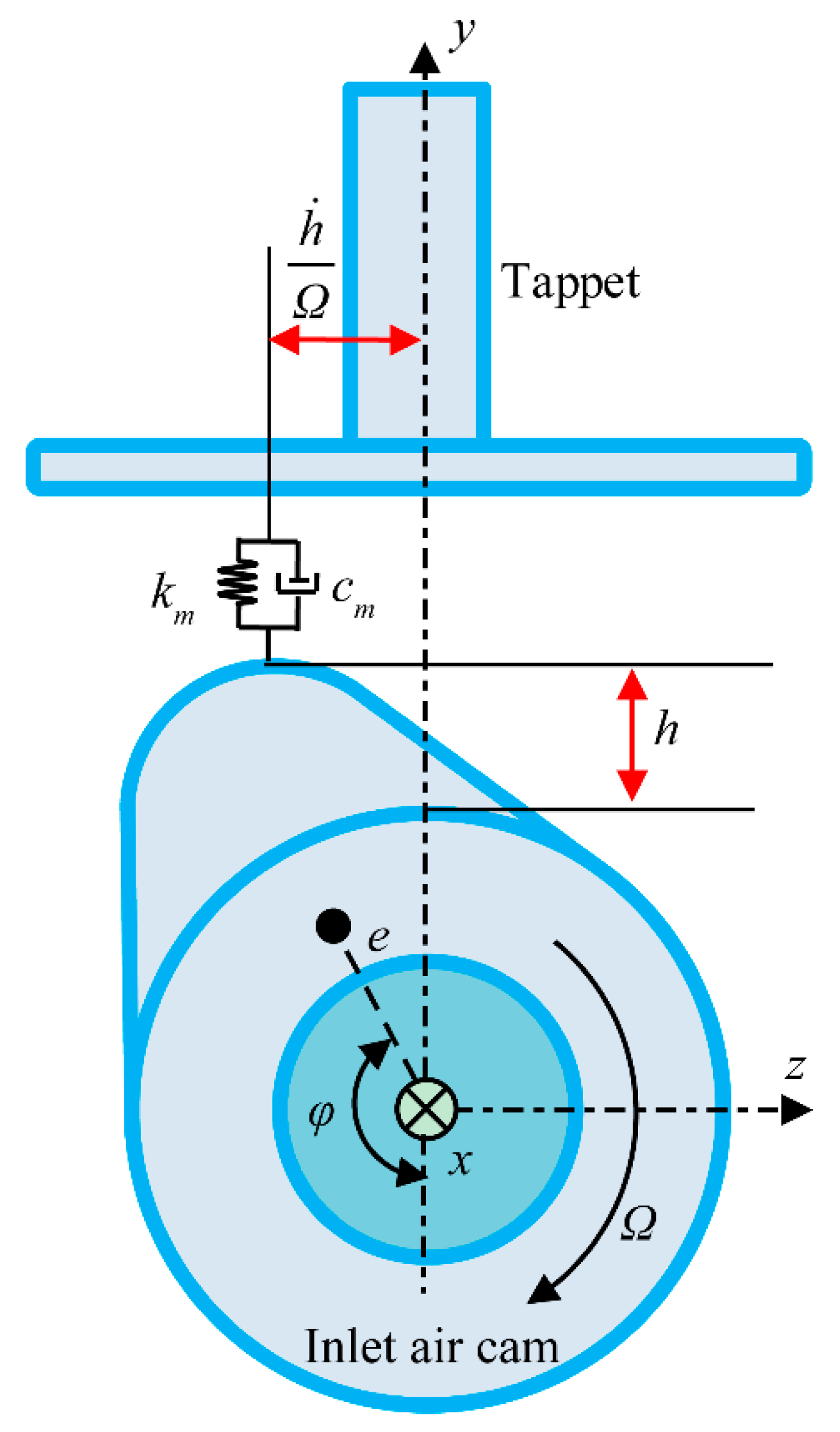
Figure 3.
Arrangement of the test rig for measuring housing vibration and pushrod stress.
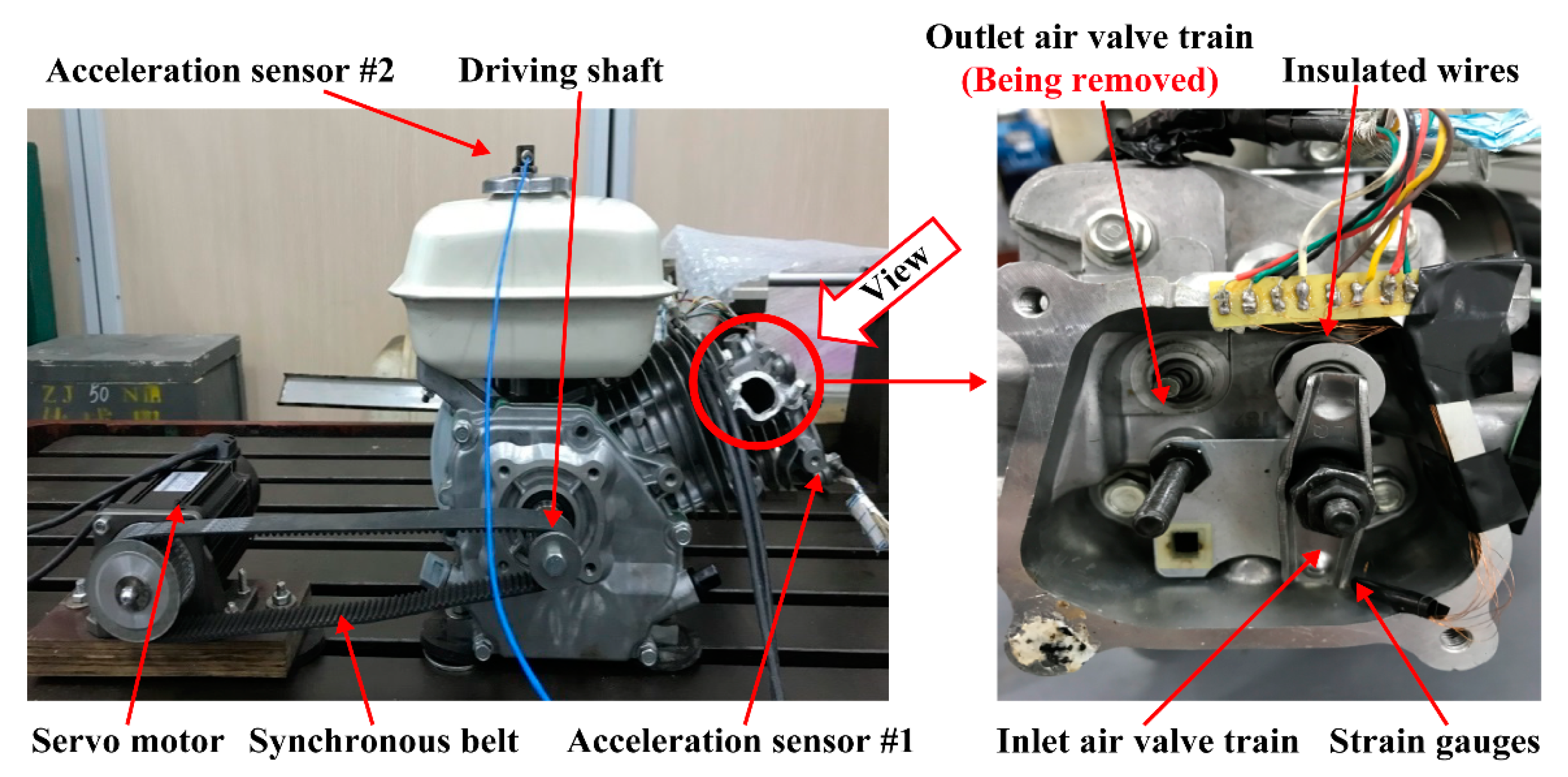
Figure 4.
Comparison of the measured and predicted vibration at cam speed of 300–2000 rpm: (a) direction x and (b) direction y.
Figure 4.
Comparison of the measured and predicted vibration at cam speed of 300–2000 rpm: (a) direction x and (b) direction y.

Figure 5.
The measured and predicted acceleration at (a) 600 rpm, (b) 900 rpm, (c) 1200 rpm and (d) 1800 rpm.
Figure 5.
The measured and predicted acceleration at (a) 600 rpm, (b) 900 rpm, (c) 1200 rpm and (d) 1800 rpm.

Figure 6.
Predicted and measured stresses at (a) 600, (b) 900, (c) 1200 and (d) 1800 rpm.
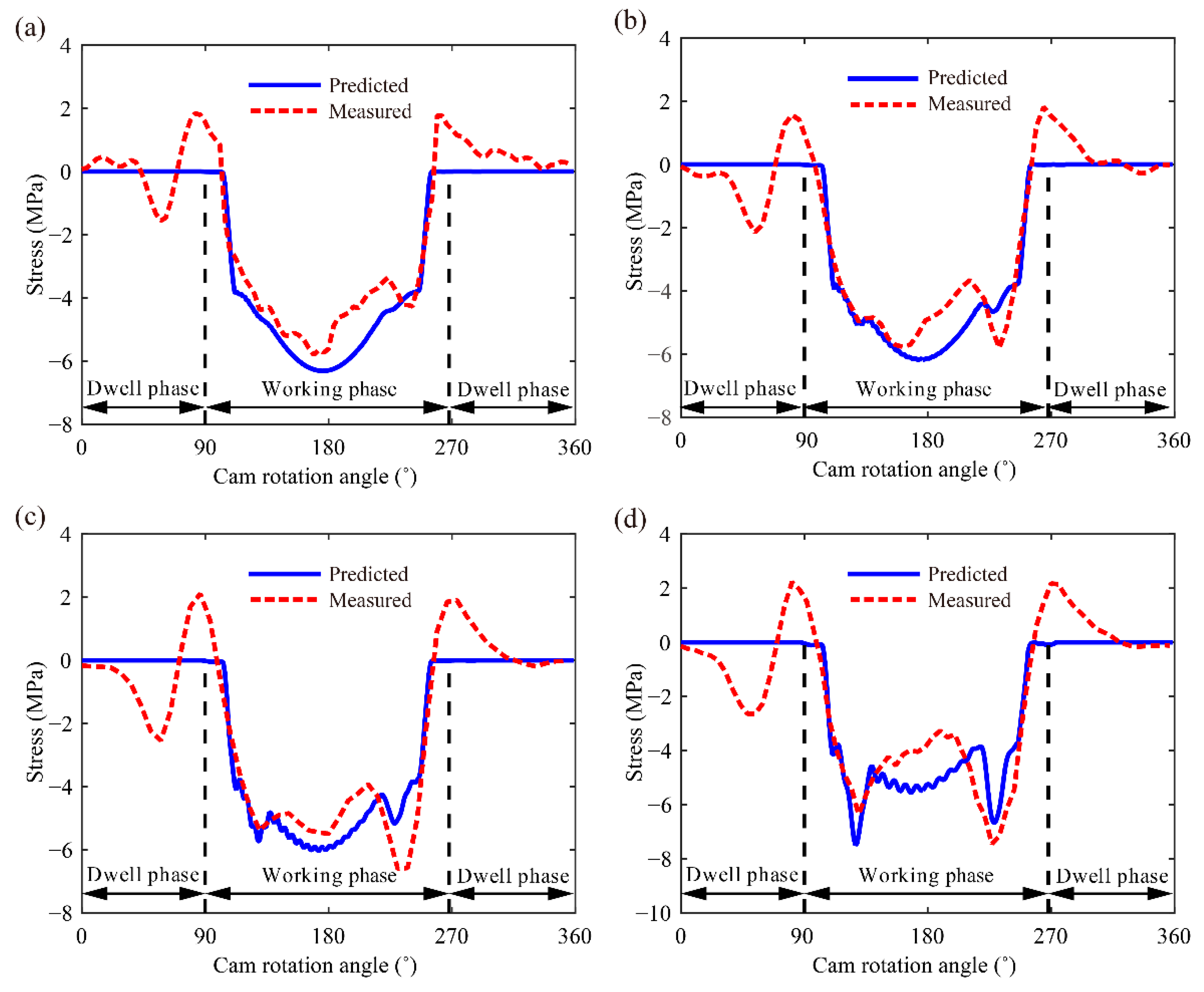
Figure 7.
Bounce and jump at different cam rotation speeds: (a) bounce and (b) jump.
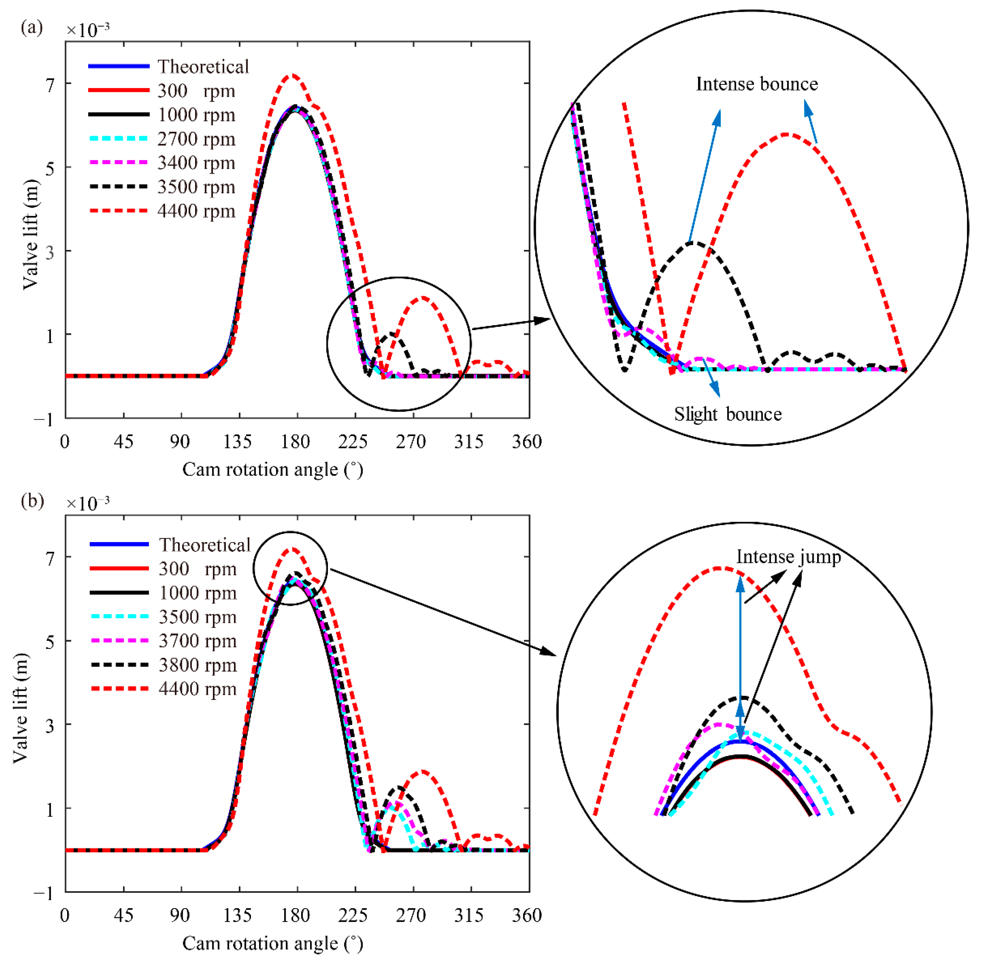
Figure 8.
Comparison of the bounce phenomenon at different valve clearances.

Figure 9.
Comparison of the jump phenomenon at different valve clearances: (a) 0.15 mm, (b) 0.55 mm, (c) 0.60 mm and (d) 1.00 mm.
Figure 9.
Comparison of the jump phenomenon at different valve clearances: (a) 0.15 mm, (b) 0.55 mm, (c) 0.60 mm and (d) 1.00 mm.


Table 1.
Structural parameters of the shaft elements.
| Element No. | Diameter (mm) | Length (mm) | Element No. | Diameter (mm) | Length (mm) | Element No. | Diameter (mm) | Length (mm) |
|---|---|---|---|---|---|---|---|---|
| Driving shaft | Camshaft | Inlet air valve train | ||||||
| ➀ | 25.00 | 13.00 | ➇ | 12.00 | 6.20 | ⑯ | 8.00 | 30.50 |
| ➁ | 25.00 | 13.00 | ➈ | 14.00 | 10.20 | ⑰ | 4.00 | 67.00 |
| ➂ | 30.00 | 11.00 | ⑩ | 14.60 | 12.85 | ⑱ | 4.00 | 67.00 |
| ➃ | 14.00 | 18.71 | ⑪ | 14.60 | 13.35 | ⑲ | 6.50 | 26.67 |
| ➄ | 14.00 | 18.71 | ⑫ | 14.60 | 15.70 | ⑳ | 6.50 | 30.67 |
| ➅ | 14.00 | 18.71 | ⑬ | 14.60 | 15.90 | ㉑ | 5.50 | 32.00 |
| ➆ | 12.00 | 18.71 | ⑭ | 14.60 | 16.78 | ㉒ | 5.50 | 32.00 |
| ⑮ | 12.00 | 11.26 | ||||||
Table 2.
Values of bearing stiffness and damping.
| Bearings Stiffness | Bearing #1 and #2 | Bearing #3 and #4 | Joint |
|---|---|---|---|
| kxx (N/m) | 6.8 × 10⁷ | 4.1 × 10⁷ | 1.1 × 10⁸ |
| kyy (N/m) | 6.8 × 10⁷ | 4.1 × 10⁷ | 1.1 × 10⁸ |
| kzz (N/m) | 5.4 × 10⁶ | 1.9 × 10⁷ | 1.1 × 10⁶ |
| kθxθx (N/rad) | 2.1 × 10³ | 1.9 × 10³ | / |
| kθyθy (N/rad) | 2.1 × 10³ | 1.9 × 10³ | / |
| kxθy,kyθx,kθxy,kθyx (N/rad) | 3.7 × 10⁵ | 2.8 × 10⁵ | / |
| c (Ns/m) | 1.0 × 10³ | 1.0 × 10³ | 1.0 × 10³ |
Table 3.
Parameters of the helical gear pair.
| Parameters | Values | Parameters | Values |
|---|---|---|---|
| m (mm) | 1.75 | JPp (kg∙m2) | 2.13 × 10⁻⁵ |
| mp (kg) | 6.00 × 10⁻² | JPg (kg∙m2) | 3.51 × 10⁻⁴ |
| mg (kg) | 3.61 × 10⁻¹ | Rp (mm) | 21.74 |
| zp | 24 | Rg (mm) | 43.48 |
| zg | 48 | αn (°) | 20 |
| JDp (kg∙m2) | 1.12 × 10⁻⁵ | β (°) | 15 |
| JDg (kg∙m2) | 1.77 × 10⁻⁴ | ζ | 0.07 |
Table 4.
Bounce and jump phenomena at different cam rotation speeds.
| Cam Rotation Speed | Bounce Phenomenon | Jump Phenomenon |
|---|---|---|
| 300 rpm | No bounce | No jump |
| 1000 rpm | No bounce | No jump |
| 2700 rpm | No bounce | No jump |
| 3400 rpm | Slight bounce | No jump |
| 3500 rpm | Intense bounce | Slight jump |
| 3700 rpm | Intense bounce | Slight jump |
| 3800 rpm | Intense bounce | Intense jump |
| 4400 rpm | Intense bounce | Intense jump |
Publisher’s Note: MDPI stays neutral with regard to jurisdictional claims in published maps and institutional affiliations. |
© 2021 by the authors. Licensee MDPI, Basel, Switzerland. This article is an open access article distributed under the terms and conditions of the Creative Commons Attribution (CC BY) license (https://creativecommons.org/licenses/by/4.0/).
Share and Cite
MDPI and ACS Style
Hu, B.; Li, Y.; Yin, L. Theoretical and Experimental Analysis of Dynamic Characteristics for a Valve Train System. Sensors 2021, 21, 6328. https://doi.org/10.3390/s21196328
AMA Style
Hu B, Li Y, Yin L. Theoretical and Experimental Analysis of Dynamic Characteristics for a Valve Train System. Sensors. 2021; 21(19):6328. https://doi.org/10.3390/s21196328
Chicago/Turabian StyleHu, Bo, Yunzhe Li, and Lairong Yin. 2021. "Theoretical and Experimental Analysis of Dynamic Characteristics for a Valve Train System" Sensors 21, no. 19: 6328. https://doi.org/10.3390/s21196328
Note that from the first issue of 2016, this journal uses article numbers instead of page numbers. See further details here.