
Architecture Design and VLSI Implementation of 3D Hand Gesture Recognition System †


Abstract
:1. Introduction
- Helping the hearing impaired;
- Recognizing sign language;
- Helping mobile drivers to control some devices without looking at them;
- Improving public health (by eliminating the need to touch public devices);
- Manipulating in virtual environments.
- We use a lower-priced dual-camera device to construct a depth map and achieve real-time 3D hand recognition;
- We implement the whole system in VLSI design and demonstrate the HCI system to verify the overall architecture.
2. Related Works
2.1. Depth Information Extraction
2.2. Area of Interest Detection
2.3. Hardware Design
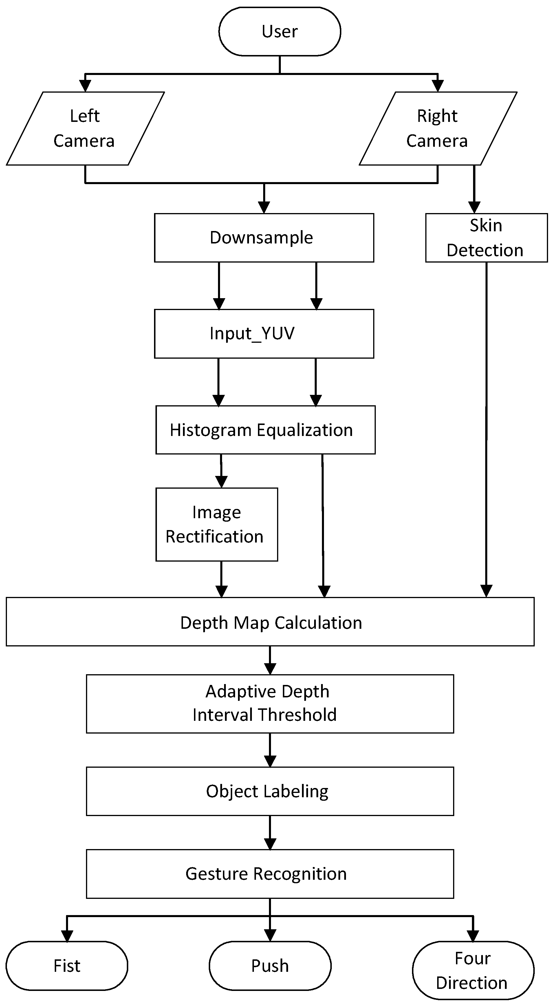
3. The Proposed System
3.1. Image Preprocessing
3.2. Stereo Matching
3.3. Skin Detection
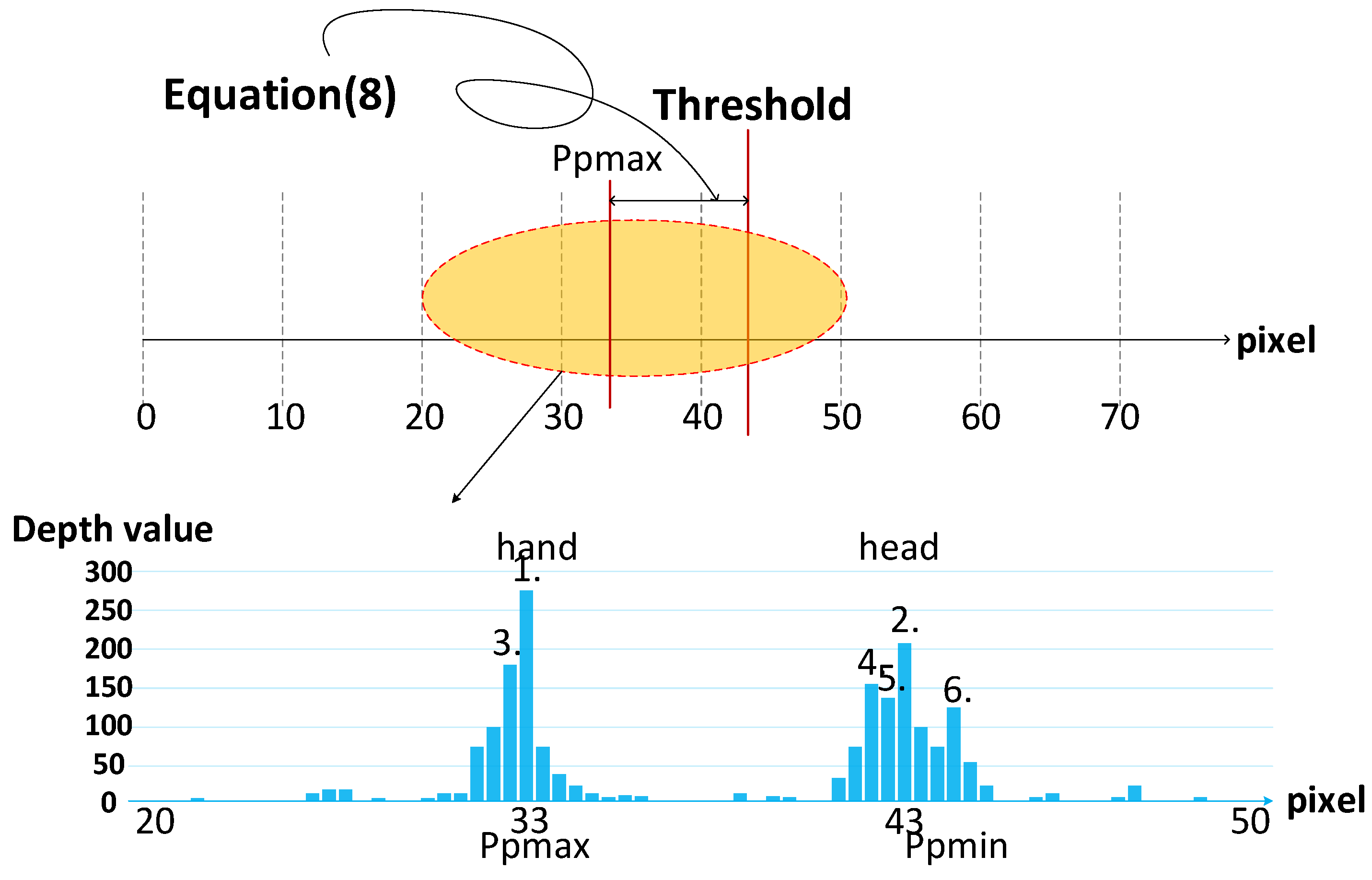
3.4. Adaptive Dynamic Threshold
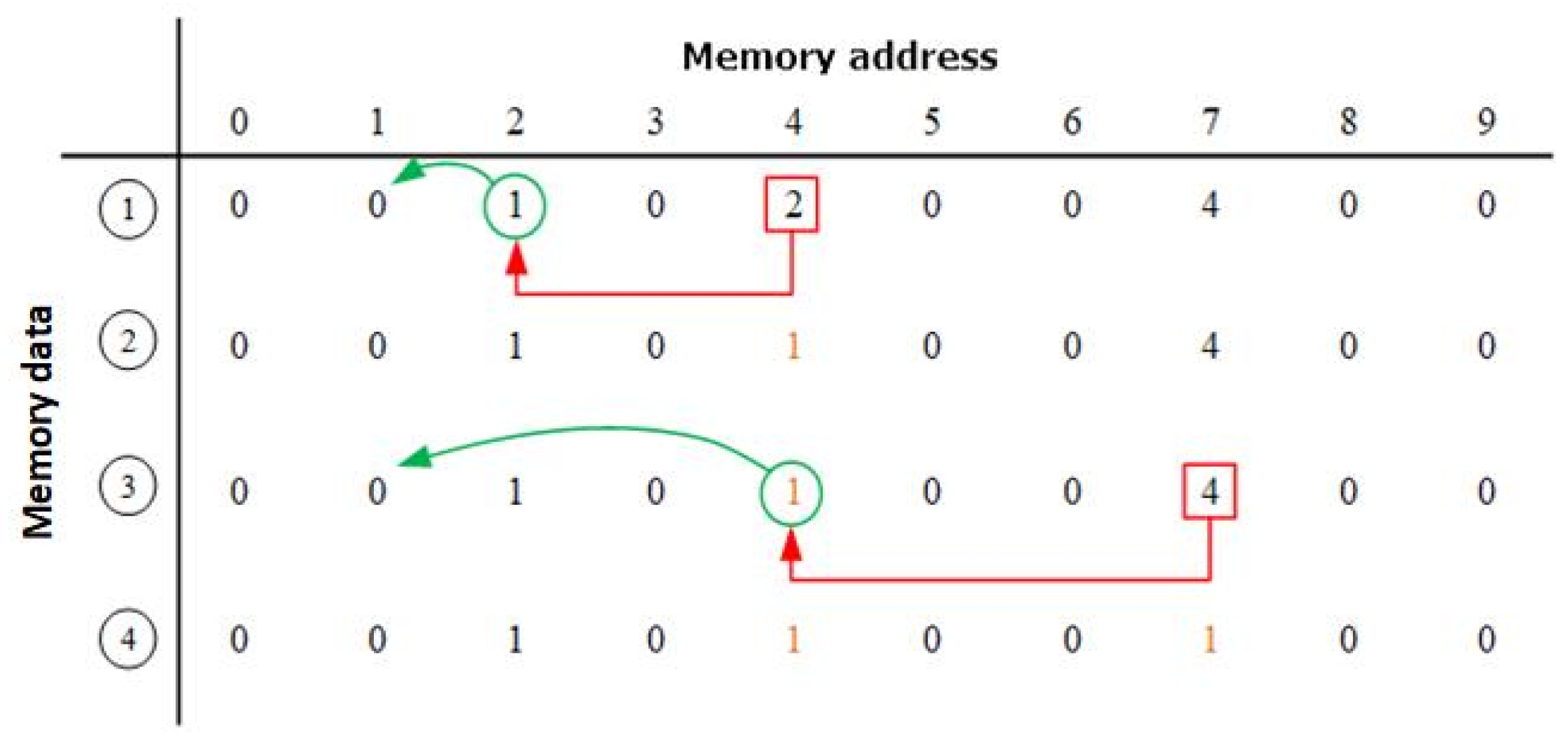
3.5. Object Labeling
3.6. Hand Segmentation
| Algorithm 1. Pseudocode for the algorithm to determine push gesture threshold |
| Input: fist, current depth Output: threshold Initialization: count = 0 Begin 1: for i = 1:n do 2: if(fist = 1 & count = 0) 3: threshold = current depth +c 4: count = 1 5: else if (fist = 1) 6: threshold = threshold 7: else count = 0 8: end |
4. Experimental Results
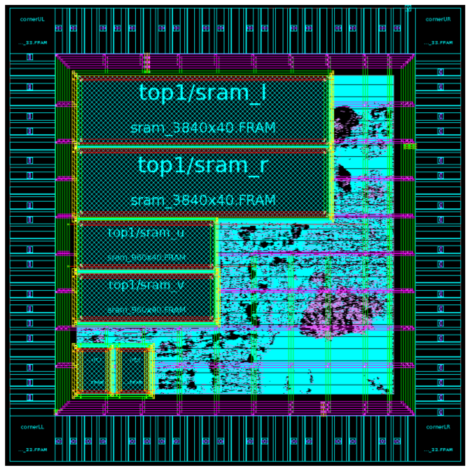
4.1. ASIC Design
4.2. FPGA Implementation and Demonstration
5. Conclusions
Author Contributions
Funding
Institutional Review Board Statement
Informed Consent Statement
Data Availability Statement
Conflicts of Interest
References
- Mitra, S.; Acharya, T. Gesture recognition: A survey. IEEE Trans. Syst. Man Cybern. Part C (Appl. Rev.) 2007, 37, 311–324. [Google Scholar] [CrossRef]
- Kumar, P.; Rautaray, S.S.; Agrawal, A. Hand data glove: A new generation real-time mouse for human-computer interaction. In Proceedings of the International Conference on Recent Advances in Information Technology (RAIT), Dhanbad, India, 15–17 March 2012; pp. 750–755. [Google Scholar]
- Wachs, J.P.; Lsch, M.K.; Stern, H.; Edan, Y. Vision-based handgesture applications. Commun. ACM 2011, 54, 60–71. [Google Scholar] [CrossRef] [Green Version]
- Ghosh, D.K.; Ari, S. Static Hand Gesture Recognition Using Mixture of Features and SVM Classifier. In Proceedings of the 2015 Fifth International Conference on Communication Systems and Network Technologies, Gwalior, India, 4–6 April 2015; pp. 1094–1099. [Google Scholar]
- Huang, T.H.; Zhuang, Z.Q.; Chen, C.Y.; Chang, B.R.; Lin, P.C.; Ou, Y.Y. An Interactive Musical Application with Hand Motion and Gesture Controlled Interface. In Proceedings of the IEEE International Conference on Orange Technologies (ICOT), Hong Kong, China, 19–22 December 2015; pp. 185–188. [Google Scholar]
- Introducing the ZED Mini, Our New Depth Camera for Mixed-Reality. Available online: https://www.stereolabs.com/ (accessed on 14 March 2018).
- Manresa, C.; Varona, J. Hand tracking and gesture recognition for human-computer interaction. Electron. Lett. Comput. Vis. Image Anal. 2005, 5, 96–104. [Google Scholar] [CrossRef]
- Bretzner, L.; Laptev, I.; Lindeberg, T. Hand Gesture Recognition Using Multiscale Colour Features, Hierarchical Models and Particle Filtering. In Proceedings of the Fifth IEEE International Conference on Automatic Face and Gesture Recognition, Washington, DC, USA, 21 May 2002; pp. 423–428. [Google Scholar]
- Tsai, T.H.; Tsai, Y.R. Design and Implementation of a 3D Hand Gesture Architecture System under COMPLICATED environment. In Proceedings of the 2017 International Symposium on VLSI Design, Automation and Test (VLSI-DAT), Hsinchu, Taiwan, 24–27 April 2017. [Google Scholar]
- Tsai, T.-H.; Ho, Y.-C. Implementation of 3D Hand Gesture Recognition System using FPGA. In Proceedings of the International SOC Design Conference (ISOCC), Daegu, Korea, 12–15 November 2018. [Google Scholar]
- Ju, K.; Wang, B.; Xiong, H. Structure-aware Priority Belief Propagation for Depth Estimation. In Proceedings of the IEEE Visual Communications and Image Processing (VCIP), Singapore, 13–16 December 2015; pp. 1–4. [Google Scholar]
- Kordelas, G.A.; Alexiadis, D.S.; Daras, P.; Izquierdo, E. Revisiting Guide Image Filter Based Stereo Matching and Scanline Optimization for Improved Disparity Estimation. In Proceedings of the IEEE International Conference on Image Processing (ICIP), Paris, France, 27–30 October 2014; pp. 3803–3807. [Google Scholar]
- Hisatomi, K.; Kano, M.; Ikeya, K.; Katayama, M.; Mishina, T.; Aizawa, K. Depth Estimation Based on an Infrared Projector and an Infrared Color Stereo Camera by Using Cross-based Dynamic Programming with Cost Volume Filter. In Proceedings of the IEEE International Conference on 3D Vision (3DV), Lyon, France, 19–22 October 2015; pp. 580–588. [Google Scholar]
- Zhang, C.; Bastian, J.; Shen, C.; van den Hengel, A.; Shen, T. Extended depth-of-field via focus stacking and graph cuts. In Proceedings of the IEEE International Conference on Image Processing (ICIP), Melbourne, VIC, Australia, 15–18 September 2013; pp. 1272–1276. [Google Scholar]
- Rahmat, R.W.; Al-Tairi, Z.H.; Saripan, M.I.; Sulaiman, P.S. Removing Shadow for Hand Segmentation Based on Background Subtraction. In Proceedings of the International Conference on Advanced Computer Science Applications and Technologies (ACSAT), Kuala Lumpur, Malaysia, 26–28 November 2012; pp. 481–485. [Google Scholar]
- Mesbahi, S.C.; Marhraz, M.A.; Riffi, J.; Tairi, H. Hand gesture recognition based on convexity approach and background subtraction. In Proceedings of the IEEE International Conference on Intelligent Systems and Computer Vision (ISCV), Fez, Morocco, 2–4 April 2018. [Google Scholar]
- Hasan, M.M.; Mishra, P.K. HSV Brightness Factor Matching for Gesture Recognition System. Int. J. Image Process. 2010, 4, 456–467. [Google Scholar]
- Chen, Q.; Georganas, N.D.; Petriu, E.M. Hand Gesture Recognition Using Haar-Like Features and a Stochastic Context-Free Grammar. IEEE Trans. Instrum. Meas. 2008, 57, 1562–1571. [Google Scholar] [CrossRef]
- Huang, P.; Lin, T.; Lin, H.; Wu, C.; Hsiao, C.; Liao, C.; Lemmens, P. Real-time stereo matching for 3D hand gesture recognition. In Proceedings of the IEEE International SoC Design Conference (ISOCC), Jeju, Korea, 4–7 November 2012; pp. 29–32. [Google Scholar]
- Ko, C.; Li, C.; Chung, C.; Chen, L. 3D Hand Localization by Low Cost Webcams. In Proceedings of the IS&T/SPIE Electronic Imaging (IS&T/SPIE EI), Burlingame, CA, USA, 3–7 February 2013. [Google Scholar]
- Shan, Y.; Wang, Z.; Wang, W.; Hao, Y.; Wang, Y.; Tsoi, K.; Luk, W.; Yang, H. FPGA Based Memory Efficient High Resolution Stereo Vision System for Video Tolling. In Proceedings of the 2012 International Conference on Field-Programmable Technology, Seoul, Korea, 10–12 December 2012; pp. 29–32. [Google Scholar]
- Raj, S.M.A.; Sreelatha, G.; Supriya, M.H. Gesture Recognition Using Field Programmable Gate Arrays. In Proceedings of the 2012 International Conference on Devices, Circuits and Systems (ICDCS), Coimbatore, India, 15–16 March 2012. [Google Scholar]
- Cho, P.-C.; Li, C.-T.; Chen, W.-H. Implementation of Low-Cost Vision-Based Gesture Recognition Systems Based on Fpga Approach. In Proceedings of the 2012 International Symposium on Computer, Consumer and Control (IS3C), Taichung, Taiwan, 4–6 June 2012; pp. 329–332. [Google Scholar]
- Wang, R.; Yu, Z.; Liu, M.; Wang, Y.; Chang, Y. Real-time Visual Static Hand Gesture Recognition System and Its FPGA-Based Hardware Implementation. In Proceedings of the 2014 12th International Conference on Signal Processing (ICSP), Hangzhou, China, 19–23 October 2014; pp. 434–439. [Google Scholar]
- Núñez-Prieto, R.; Gómez, P.C.; Liu, L. A Real-Time Gesture Recognition System with FPGA Accelerated ZynqNet Classification. In Proceedings of the 2019 IEEE Nordic Circuits and Systems Conference (NORCAS): NORCHIP and International Symposium of System-on-Chip (SoC), Helsinki, Finland, 29–30 October 2019; pp. 1–6. [Google Scholar]
- Smith, A.R. Color gamut transform pairs. ACM Siggraph Comput. Graph. 1978, 12, 12–19. [Google Scholar] [CrossRef]
- Zhang, Z. Determining the Epipolar Geometry and its Uncertainty:A Review. Int. J. Comput. Vis. 1998, 27, 161–195. [Google Scholar] [CrossRef]
- Xia, Y.; Guo, L.; Huang, M.; Ma, R. A New Fast Matching Approach of Large Disparity Stereopair. In Proceedings of the 2008 Congress on Image and Signal Processing, Sanya, China, 27–30 May 2008; pp. 286–290. [Google Scholar]
- Algorithms, K.P. Complexity Analysis and VLSI Architectures for MPEG-4 Motion Estimation; Kluwer Academic: Amsterdam, The Netherlands, 1999. [Google Scholar]
- Perri, S.; Colonna, D.; Zicari, P.; Corsonello, P. SAD-Based Stereo Matching Circuit for FPGAs. In Proceedings of the 2006 13th IEEE International Conference on Electronics, Circuits and Systems, Nice, France, 10–13 December 2006; pp. 846–849. [Google Scholar]
- Al-Tairi, Z.H.; Rahmat, R.W.; Saripan, M.I.; Sulaiman, P.S. Skin Segmentation Using YUV and RGB Color Spaces Puteri Suhaiza Sulaiman. J. Inf. Process. Syst. 2014, 10, 283–299. [Google Scholar] [CrossRef] [Green Version]


| Raj [20] | Cho [21] | Wang [22] | Núñez-Prieto [23] | This Work | |
|---|---|---|---|---|---|
| Camera | Single-camera | Single-camera | Single-camera | Single-camera | Dual camera |
| Platform | Virtex-4 ML402 | ALTERA Cyclone II EP2C70 | Virtex-5 XC5VLX50T | xcku060 | SMIMS VEXA7-200 |
| Remarks | Skin-detection Centroid calculation Finger count determination | Skin-color-detector Optical flow operator Kalman filter | Skin-detection Median filter Fingertip detection | CNN ZynqNet | SAD Skin-detection Object-Labeling Trajectory-detection |
| Image size | -- | 640 × 480 | 640 × 480 | -- | 1280 × 720 |
| Frequency | -- | 125 MHz | N/A | 200 MHz | 420 MHz |
| Frame rate | -- | 75FPS | 60FPS | 23.5FPS | 60FPS (180FPS@640*480) |
| Throughput (pixel per second) | -- | 230.4 M | 180.3 M | 15.4 M | 553 M |
| Slice Register | 14,053 | 7251 | 6421 | 71,000 | 6051 (2%) |
| Slice LUTs | 39,540 | 16,806 | 12,633 | 293,000 | 8204 (6%) |
| Bonded IOBs | 463 | 447 | 22 | -- | 178 (44%) |
| Gesture classes | 5 static | 2 static 4 dynamic | 5 static | 29 static | 1 static, 5 dynamic (2Dx4 + 3Dx1) |
| Item | Specification |
|---|---|
| Technology | TSMC 90 nm |
| Voltage | 1.0 V / 3.3 V (Core / IO) |
| Operation frequency | 420 MHz |
| Chip area | 1.580 mm × 1.610 mm |
| Core area | 1.020 mm × 1.048 mm |
| Gate count | 47.3 K |
| Memory requirement | 1.25 KBytes |
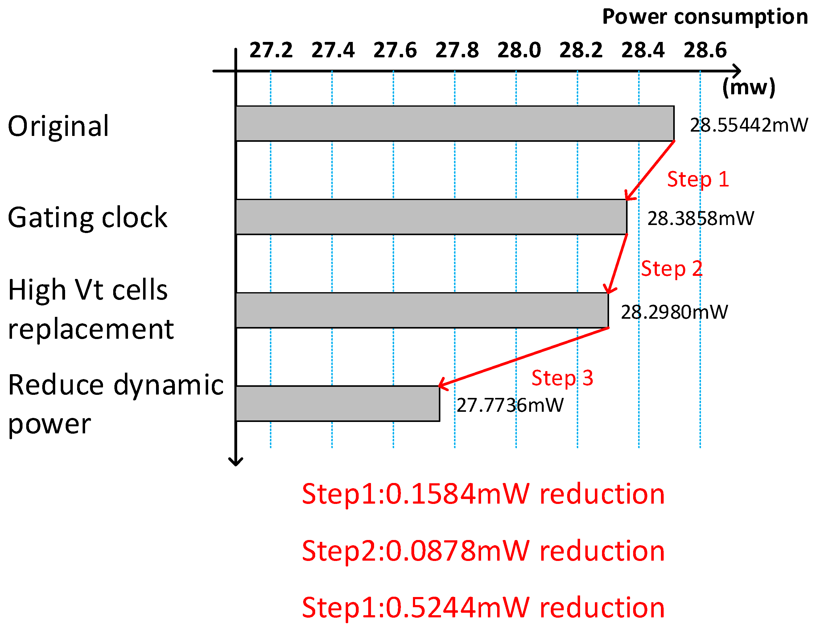
| Power consumption | 27.7736 mW |
| Total pins | 102 pins |
| Gesture | Samples | Hit | Miss | Average |
|---|---|---|---|---|
| Fist | 1000 | 912 | 88 | 91.2% |
| Push | 1000 | 848 | 152 | 84.8% |
| Four direction | 1000 | 813 | 187 | 81.3% |
| Push + Four direction | 1000 | 786 | 214 | 78.6% |
| Total | 4000 | 3359 | 641 | 83.98% |
Publisher’s Note: MDPI stays neutral with regard to jurisdictional claims in published maps and institutional affiliations. |
© 2021 by the authors. Licensee MDPI, Basel, Switzerland. This article is an open access article distributed under the terms and conditions of the Creative Commons Attribution (CC BY) license (https://creativecommons.org/licenses/by/4.0/).
Share and Cite
Tsai, T.-H.; Tsai, Y.-R. Architecture Design and VLSI Implementation of 3D Hand Gesture Recognition System. Sensors 2021, 21, 6724. https://doi.org/10.3390/s21206724
Tsai T-H, Tsai Y-R. Architecture Design and VLSI Implementation of 3D Hand Gesture Recognition System. Sensors. 2021; 21(20):6724. https://doi.org/10.3390/s21206724
Chicago/Turabian StyleTsai, Tsung-Han, and Yih-Ru Tsai. 2021. "Architecture Design and VLSI Implementation of 3D Hand Gesture Recognition System" Sensors 21, no. 20: 6724. https://doi.org/10.3390/s21206724
APA StyleTsai, T.-H., & Tsai, Y.-R. (2021). Architecture Design and VLSI Implementation of 3D Hand Gesture Recognition System. Sensors, 21(20), 6724. https://doi.org/10.3390/s21206724