
Assessing Cyber Risks of an INS Using the MITRE ATT&CK Framework


Department of Information Security and Communication Technology, Norwegian University of Science and Technology, 2815 Gjøvik, Norway
*
Author to whom correspondence should be addressed.
Sensors 2022, 22(22), 8745; https://doi.org/10.3390/s22228745
Submission received: 17 September 2022
/
Revised: 25 October 2022
/
Accepted: 7 November 2022
/
Published: 12 November 2022
(This article belongs to the Section Sensor Networks)
Abstract
:Shipping performed by contemporary vessels is the backbone of global trade. Modern vessels are equipped with many computerized systems to enhance safety and operational efficiency. One such system developed is the integrated navigation system (INS), which combines information and functions for the bridge team onboard. An INS comprises many marine components involving cyber threats and vulnerabilities. This study aims to assess the cyber risks of such components. To this end, a methodology considering the MITRE ATT&CK framework, which provides adversarial tactics, techniques, and mitigation measures, was applied by modifying for cyber risks at sea. We assessed cyber risks of 25 components on the bridge by implementing the extended methodology in this study. As a result of the assessment, we found 1850 risks. We classified our results as 1805 low, 32 medium, 9 high, and 4 critical levels for 22 components. Three components did not include any cyber risks. Scientists, ship operators, and product developers could use the findings to protect navigation systems onboard from potential cyber threats and vulnerabilities.
1. Introduction
Over 80% of goods in international trade are carried by ships [1]. One of the most essential elements of maritime transportation is explicitly ships. In 2020, the worldwide merchant fleet grew by 3% and reached 99,800 ships of 100 gross tons and above [1]. Contemporary ships are equipped with computerized systems for different purposes, such as navigation, communication, propulsion, and cargo handling. The safety and operational efficiency of vessels are improved because of such systems. However, these systems are accompanied by growing cyber security concerns in the maritime industry because of experiencing cyber incidents and revealing research results.
The International Maritime Organization (IMO) is the responsible agency in the United Nations for the safety and security of shipping and the prevention of environmental pollution by ships [2]. Maritime cyber risk is defined by the IMO as “a measure of the extent to which a technology asset is threatened by a potential circumstance or event, which may result in shipping-related operational, safety or security failures as a consequence of information or systems being corrupted, lost or compromised” [3]. In 2017, the IMO issued a resolution to prevent maritime cyber risks [4]. As per the resolution in force, cyber risks must be assessed by ship operators and addressed in their approved Safety Management Systems (SMS). Moreover, they should make reference to the Ship Security Plan (SSP) as per the International Ship and Port Facility Security (ISPS) Code [5,6]. This requirement has been verified in the Document of Compliance (DOC) audits of ship operators since 2 January 2021.
This paper reveals the significance of cyber risks onboard vessels. We contributed to the literature by extending a methodology using the MITRE ATT&CK framework to assess the cyber risks of systems onboard ships. Moreover, the method was implemented to specifically assess the cyber risks of an INS in this study. A total of 1850 risks were classified as 1805 low, 32 medium, 9 high, and 4 critical levels. Given that no marine casualty (e.g., collision, explosion, injury, and oil spill) caused by cyber attacks was found in the literature, safety and environmental impacts of cyber risks are outside of the scope of this study.
We organised the remainder of the paper as follows. Section 2 gives a review of the related literature. In Section 3, the methodology is discussed and implemented for the cyber risks of an INS. Section 4 offers a summary and suggests additional research topics for further investigation. Consequently, in Appendix A, cyber risks of medium, high, and critical levels are listed.
2. Background
2.1. INS Concept
The IMO defines an INS as “A system in which the information from two or more navigation aids is combined in a symbiotic manner to provide an output that is superior to any one of the component aids” [7]. The INS aims to improve safe navigation by combining and integrating information and functions for the Officer of the Watch (OOW) in planning, monitoring, and controlling ship navigation [8]. An INS constitutes six navigational tasks as mandatory and optional, as follows:
- Route Monitoring: “The navigational task of continuous surveillance of own ships position in relation to the pre-planned route and the waters” [9].
- Route Planning: The task that provides procedures for voyage planning, route planning functions and data for the Electronic Chart Display and Information System (ECDIS), administering the route plan, checking route plan against hazards, manoeuvring limitation (e.g., rate of turn (ROT)), drafting and refining the route plan against meteorological information [8].
- Collision Avoidance: “The navigational task of detecting and plotting other ships and objects to avoid collisions” [9].
- Navigation Control Data: “Task that provides information for the manual and automatic control of the ship’s movement on a task station” [9].
- Navigational Status and Data Display: The task that displays data for the manual and automatic control of the ship’s primary movement [8].
- Alert Management: “Concept for the harmonized regulation of the monitoring, handling, distribution and presentation of alerts on the bridge” [9].
2.2. MITRE ATT&CK Framework
The ATT&CK framework (which stands for Adversarial Tactics, Techniques, and Common Knowledge) has been developed by MITRE since 2013 [10]. It is a globally accessible database including attack tactics, techniques, and mitigation measures for the matrices of enterprise, mobile, and industrial control systems (ICS). The Enterprise Matrix covers offensive information (i.e., tactics and techniques) for information technology (IT) networks and cloud services, such as operating systems (i.e., Windows, Linux, and macOS), network components, Office 365, and Google Workspace [11,12]. The Mobile Matrix includes offensive knowledge for iOS and Android platforms [13]. The ICS Matrix provides offensive information for the ICS [14]. The Tactics represents the attack objective, such as initial access, credential access, and lateral movement [15]. Techniques expresses methods to achieve an attack objective [16]. The ATT&CK framework also provides mitigation measures to avoid a technique from being successfully executed [17]. Moreover, malware and tools which can be used for malicious purposes are described under the name of Software [18]. Another important dimension of ATT&CK is to offer cyber-threat intelligence. Groups refers to adversary actor and give techniques implemented and software used by them for an attack in the past [19]. Data Sources provides information about various subjects and notions [20].
2.3. Literature Review
In the literature, papers implementing various methods have assessed the cyber risks of autonomous ships and conventional ships. Kavallieratos and Katsikas [21] implemented STRIDE and DREAD methods for the cyber risk assessment of several systems on the autonomous ship, such as a collision avoidance system, RAdio Detecting Additionally Ranging (RADAR), closed-circuit television (CCTV), Voyage Data Recorder (VDR), cargo management system, and autopilot. Kavallieratos et al. in [22] also implemented STRIDE for an Automatic Identification System (AIS), engine automation system, bridge automation system, shore control center, engine efficiency system, navigation systems, autonomous ship controller, and so on. Tusher et al. [23] have a cyber risk assessment work for autonomous ships, as well. In their study, the Bayesian best–worst method was implemented, and the authors revealed navigation systems as the most vulnerable element in the context of future autonomous shipping operations. Shang et al. [24] implemented the combination of fuzzy set theory and the Attack Tree method to assess cyber risks of the control system for a gas turbine onboard ship. Oruc [25] also combined fuzzy set theory with another risk assessment method, Fine–Kinney. In the study, 31 cyber risks in the bridge, engine room, and cargo control room onboard a tanker were assessed. Moreover, the efficiency of proposed mitigation measures is shown by implementing the method a second time after taking precautions. Kessler et al. [26] focused on 16 different cyber risks of an AIS. Their study reveals that the disruption of an individual AIS message is more crucial than being unusable of an entire AIS. Svilicic et al. [27] also performed a risk assessment for a specific component. The authors made a cyber risk assessment for the ECDIS on a training vessel by using a vulnerability scanner, named Nessus Professional, and interviewing the ship crew. Several cyber threats were determined regarding the operating system, procedures, awareness, and so on. iTrust published a guideline [28] to uncover cyber risks of operational technology (OT) systems on conventional vessels, including navigation, machinery, communication, and cargo management systems. The traditional risk calculation formula (risk = severity × likelihood) was implemented to assess cyber risks. The study also proposes actionable mitigation measures. You et al. [29] focused on risk assessment methods in other fields and discussed their adaptation to the maritime industry. According to the study, Attack Tree, simulations, and models can be implemented for the cyber risk assessment of marine systems.
Novel methods other than well-established methods are also available in the literature for cyber risks onboard ships. Tam and Jones [30] developed a model-based framework for maritime cyber-risk assessment, entitled Maritime Cyber-Risk Assessment (MaCRA). The authors also implemented the method to assess the cyber risks of three autonomous ship projects in a separate paper [31]. Bolbot et al. [32] proposed a novel method, named CYber-Risk Assessment for Marine Systems (CYRA-MS), by considering the Preliminary Hazard Analysis (CPHA) method to assess cyber risks of ship systems. The authors implemented the method on navigation and propulsion control systems of a fully autonomous inland ship. Meland et al. [33] offered an alternative method for cyber risk assessment. The likelihood of a threat in new design systems is a challenge. The authors propose the threat likelihood approach to support security decision-making for new design systems in particular. Their method is the combination of current concepts, techniques, expert judgements, and domain-specific information.
The ISO 31000 is the root standard and comprises principles, a framework, and a process for risk management [34]. The standard offers a common approach for any size of organization to manage any kind of risk, including the decision-making process [34]. The ISO/TR 31004 explains the effective implementation of ISO 31000 in detail [35]. The IEC 31010 clarifies the selection and application of risk assessment techniques in different situations [36]. The ISO 27000 is another root standard and gives a general approach to information security management systems [37]. The IEC 63154 identifies requirements, test methods, and required test results against cyber incidents for shipborne navigational aids, radio, and navigational equipment [38]. The Formal Safety Assessment (FSA) [39] published by the IMO is a systematic methodology to enhance safety in the maritime industry, including the protection of human life, health, the marine environment and property by using risk analysis. The circular describes the notions, methods, and control measures for a risk assessment. The FSA gives an overall knowledge for a risk assessment in the maritime industry but is not designed specifically for cyber risk assessment.
As mentioned before, IMO issued a regulation for the assessment of cyber risks [4]. After this regulation particularly, several guidelines were published by class societies and other IMO-recognized organizations to support the maritime industry against cyber risks [40,41,42]. The Guidelines on Maritime Cyber Risk Management [42] jointly developed by several industry associations are officially recommended by the IMO [3,43]. The guidelines provide detailed explanations in different dimensions of cyber security, such as cyber threats, risk management, technical and procedural protection measures, and contingency plans, including response and recovery procedures for the maritime industry.
Various comparisons among high-level models, such as the ATT&CK framework, Cyber Kill Chain, OWASP top 10, STRIDE, and the Diamond Model exist [44,45,46,47]. Even though such models are effective in understanding processes and adversary goals, models other than the ATT&CK framework are not useful for explaining the impact of an action to another [48]. Furthermore, the ATT&CK framework depicts correlations of actions with data sources, defenses, configurations, and other countermeasures used for the security of a platform [48].
Even though ATT&CK framework is not a risk assessment method, papers using ATT&CK framework are available for different purposes in other domains, such as risk assessment and risk identification [49,50]. In our study, we reveal that the ATT&CK framework can be used for cyber risk assessment of ship systems as well. Moreover, in the literature, any risk assessment focusing on an INS was not found. Papers in the literature typically assessed the cyber risks of a few components. In our study, we assessed cyber risks for 25 marine components.
3. The Extended Methodology and Implementation
Our methodology was derived from the [51] to specialize cyber risks of vessels. The method is based on a Failure Mode Effects and Criticality Analysis (FMECA) and the MITRE ATT&CK framework. The core advantage of the original method is to reduce the need for expert judgement. Thus, the impact of bias in a risk assessment reduces. Moreover, the method is comprehensive and semi-automated. Mitigation measures for cyber risks are included. Our adapted methodology for marine systems is performed as follows:
- Components are specified and classified.
- Functions of components and data flow among components are identified.
- The failure modes for components are determined.
- Failure modes are mapped with consequences and impacts.
- Estimation criteria for criticalities are identified.
- Detection methods and existing controls are identified.
- The impact scores of components are identified.
- Risk scores are calculated and risk levels are identified.
3.1. Component Specification and Classification
Our methodology starts with the specification and classification of marine components. We implemented our risk assessment methodology on an INS in this study. An INS consists of various marine components. We found 25 components for an INS in our previous study [52]. Such components were classified by IMO and method definitions, respectively. The method definitions for the classification of components are given in Table 1 (e.g., IT, OT, Wireless). Classification by the method definitions is required for the risk assessment process. However, the classification by the IMO definitions is given to provide an additional contribution and to understand the differences between classifications in Table 2.
According to the IMO, components are divided into two groups, such as information technology (IT) and operational technology (OT), and the difference between IT and OT systems is defined as “Information technology systems may be thought of as focusing on the use of data as information”, and “Operational technology systems may be thought of as focusing on the use of data to control or monitor physical processes” [3]. Moreover, the IMO-recommended document, Guidelines on Maritime Cyber Risk Management, expresses that “IT covers the spectrum of technologies for data storing and processing, including software, hardware, and communication technologies”, and “OT includes hardware and software that directly monitors/controls physical devices and processes, typically on board.” [42]. Various maritime cyber security-related guidelines were reviewed to find a reliable classification list for marine components by such definitions. However, some marine components, such as ECDIS, RADAR, gyro compass, AIS, global positioning system (GPS), and Bridge Navigational Watch Alarm System (BNWAS) are classified as OT by several organizations [40,41,42]. A full list for INS components has not been found. We classified INS components considering IMO definitions as shown in Table 2. The table also includes columns for Type, Platform, and Technology. The Type of the components, such as sensors, Human–Machine Interface (HMI), control server, and engineering workstation was determined. For switches (e.g., the Rudder pump selector switch), we ignored the Type. If a component needs an operating system to run, it was stated in the Platform. The Technology refers to attached technologies such as Wi-Fi, cellular, and Bluetooth.
3.2. Functions of Components and Data Flow among Components
In the second step of the method, the functions of the components and data flow among the components are investigated. Such knowledge for an INS was taken from our previous article, as shown in Table 3 [52]. Data flow in the table was identified as per the minimum requirements of the IMO. However, additional connections among the components are allowed.
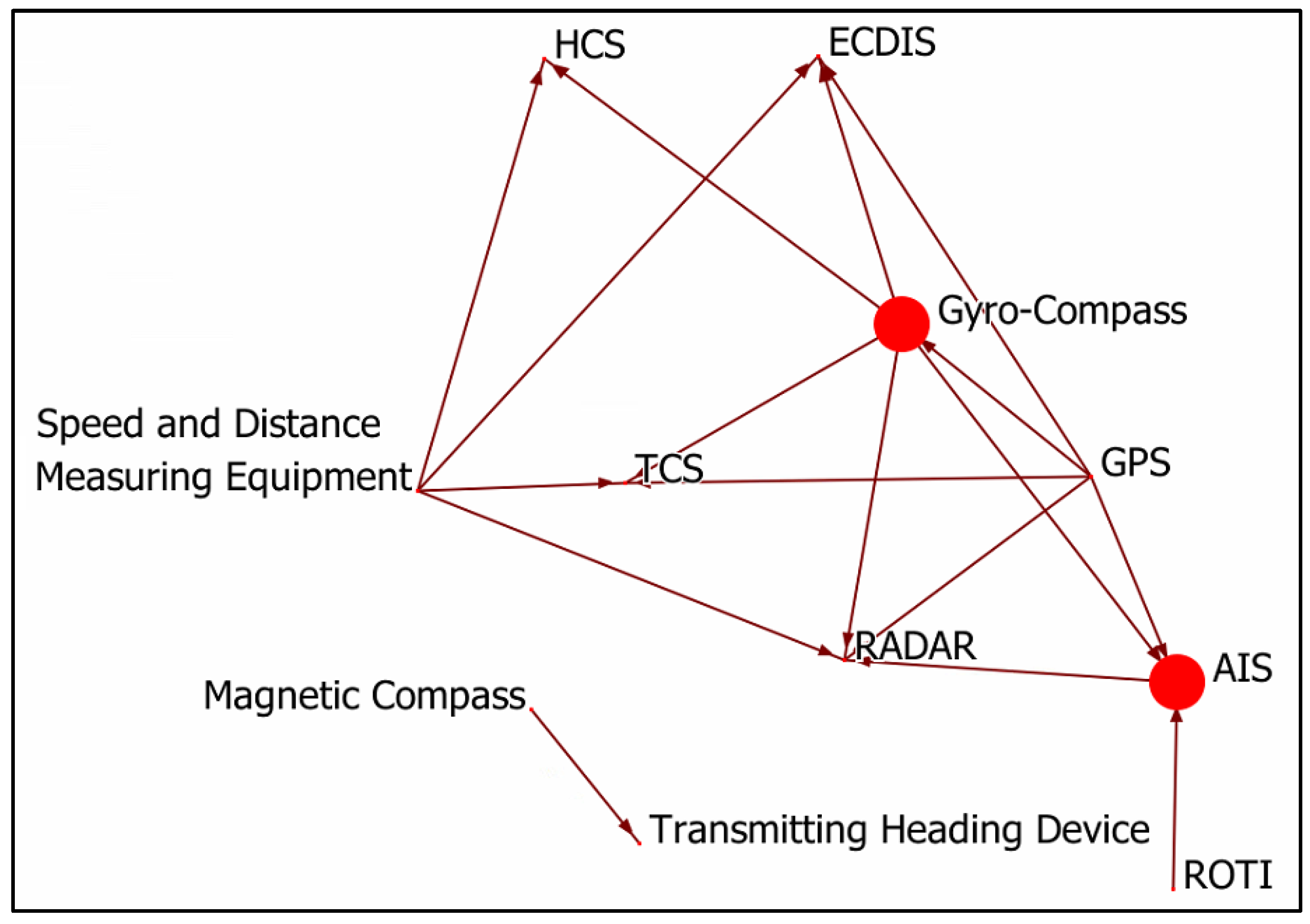
The ORA is a network tool to analyze, visualize, fuse, and forecast behaviour given network data [53]. Vulnerabilities, model network changes over time, and key players can be identified and formatted reports can be received [54]. Moreover, it consists of tools for optimizing a network’s design structure [54]. In our study, the ORA was employed to calculate various centrality metrics, such as authority, betweenness, and in-degree. Then, the dependency graph was drawn, based on Table 3. The dependency graph among the components is illustrated in Figure 1. In this graph, the nodes represent the investigated component in the INS while the edges represent the identified data flow between components. For instance, as stated in Table 3, the GPS component sends positioning information to the AIS component. This dictates the definition of an edge originating from the GPS component to the AIS component. Additionally, the node size highlights the importance of the node in the network, which is inferred from the nodes’ centrality measurements.
3.3. Identifying Failure Modes
The literature was reviewed to understand occurred cyber incidents onboard ships and threats and vulnerabilities of the marine components found in research activities. Moreover, the guidelines of products were reviewed to understand potential failures of components. Component damages and installation mistakes were ignored. In this way, potential failures caused by a cyber attack were determined. Then, failure modes were determined. In this study, failure mode refers to Tactics [15] in the ATT&CK framework and is given in three categories, such as Mobile, Enterprise, and ICS. Samples of findings are represented in Table A2.
Then, the possible causes of failure modes or attack techniques were identified and their likelihood was estimated. The identification was performed component-by-component by detecting relationships between components and techniques based on matching attributes. The ATT&CK framework provides attributes of relevant asset types and platforms for each technique. This allows for the identification of the relevant techniques for each component in the system based on the system category. For instance, “Alarm Suppression” is an attack technique against several categories of ICS components such as “RTU”; therefore, “Alarm Suppression” technique would be assigned among the threats identified for any system component that can be categorized as an “RTU”. Afterwards, the likelihood of each technique was calculated based on the exploitability score in the Common Vulnerability Scoring System (CVSS). This entails the estimation of the techniques likelihood based on a Bayesian network of four elements, namely, Attack Complexity (AC), Privilege Required (PR), Attack Vector (AV) and User Interaction (UI) using Equation (1):
Equation (1) is adapted from the CVSS for calculating the exploitability score to maintain alignment with a widely recognized approach for calculating likelihood [55]. The AC, PR, AV, and UI information was system-independent and encoded in a Threat Description Table (TDT), and was adopted for all the list of techniques from the original methodology [51].
3.4. Mapping Failure Modes with Consequences and Impacts
The consequence is an outcome of an accident [39]. In the original method, consequences are identified as operational, safety, information, financial, and staging. The IMO recommends assessing environmental risks in the FSA [39]. Moreover, we investigated several risk assessment matrices used in the maritime industry and noticed that reputation consequence is also assessed by tanker operators, in particular. Because of such reasons, we extended the method with reputation and environmental consequences.
Safety Consequence depicts the potential to cause harm to persons (e.g., crew and passengers). Operational Consequence describes potential disruptions, such as errors in the systems during cargo handling. Financial Consequence refers to economic losses such as component damages, or commercial losses (e.g., charter party violations). Information Consequence explains possible privacy or/and confidentiality violations, such as hosted and processed data in a component. Staging Consequence describes the effect of a failure mode which facilitates the staging of future attacks. Environmental Consequence describes the potential to cause harm to the environment (e.g., air and water pollution). Reputation Consequence describes harm to company prestige and business life.
Operational, Information, and Staging consequences were broken into impacts. Three metrics are available for estimating the impact on operational consequence, namely the Overall Operational Impact (OOI), Impact to the Control Functions (I2CF), and Impact to the Monitoring Functions (I2MF). If a failure mode (e.g., manipulation of control) impacts the control, it is estimated using the I2CF. If a failure mode (e.g., loss of view) impacts monitoring, it is estimated using the I2MF. Others are estimated using the OOI metric. Staging was estimated using Overall Component Criticality (OCC) and Outbound Degree Centrality (ODC). The failure modes of persistence, defense evasion, and privilege were estimated using the OCC. Others are estimated using the ODC metric. Three types of metrices exists for the information consequence. These are Data Criticality (DC), Intellectual Property Criticality (IPC), and Location Information Criticality (LIC). DC relates to hosted and processed data in a component (e.g., crew information). IPC relates to the hosting of processes with intellectual value. LIC relates to the location information of a component (e.g., position information of a vessel).
Any components in the context of an INS do not process or host personal and confidential data. One feature of an AIS is to transmit location information frequently. When an AIS is equipped mandatorily, it must be always active at anchor and underway unless the master decides to switch it off due to safety and security concerns [56]. However, this decision should be recorded in the logbook with reasons and reported to authorities [56]. Moreover, Long-Range Identification and Tracking (LRIT) onboard also transmit position information [57]. Because of such regulations, the position information of a vessel can not be confidential. Components of an INS are easily found in the market. Furthermore, component standards are identified by the IMO. This is why intellectual property does not existing for an INS. Because of such reasons, an INS is not subject to information consequences. Failure modes were mapped with other consequences and potential impacts for an INS, as illustrated in Table 4.
3.5. Identified Estimation Criteria for Criticalities
The estimation criteria were identified for safety, financial, environmental, and reputational criticalities. We proposed estimation criteria for such criticalities. The scores in the estimation criteria tables were identified between 0 and 1 using their impact degrees. Table 5 was used to estimate the impact of a failure mode on the safety consequence. Table 6 was used to forecast financial criticality. The estimation criteria for environmental criticality are depicted in Table 7. Table 5 and Table 7 were derived from the Appendix 4—Initial Ranking of Accident Scenarios in the FSA published by the IMO [39].
Because of cyber incidents, the seaworthiness and cargo worthiness of a ship may be lost or the ship might be delayed to its destination port. In such cases, the master may need to inform charterers or maritime regulators, such as the port state, flag state, and class society. This would explicitly damage the reputation of the ship operator. This is why we identified two criteria for reputation criticality, as shown in Table 8.
3.6. Identifying Detection Methods and Existing Controls
Technical and procedural mitigation measures for enterprise [17], mobile [58], and ICS [59] matrices are given in the ATT&CK framework. Over 70 mitigation measures were assessed for each component in the context of an INS. In Table 9, samples of mitigation measures for components are illustrated. The number “1” in the table refers to that the mitigation measure can be implemented for the component. On the other hand, “0” in the table denotes that the mitigation measure cannot be implemented for the component.
This table assists in calculating the detectability of techniques that can be addressed by certain mitigation measures. Detectability is a term utilized in the original methodology [51] that refers to the degree of risk reduction due to the availability of risk mitigation measures. The detectability of a technique when targeting a specific component is calculated based on Equation (2):
The coverage of a mitigation measure (M) for a component (C) is referred to in Table 9 while the efficiency of a mitigation measure (M) in reducing the risk of a technique (T) is estimated for each mitigation measure. In this paper, for simplicity, the efficiency was assumed as 0.5 for all mitigation measures due to the lack of such estimation.
3.7. Identifying Impact Scores of Components
Information impacts (i.e., IPC, DC, LIC) were not available for an INS as mentioned in Section 3.4. During the literature review, no incidents harming humans or the environment were found to be caused by cyber attacks against a vessel. This is why safety criticality and environmental criticality were assumed to be in the category None—No injury or insufficient data. Various aspects affect financial losses, including violation of the charter party agreement, daily operational expenses, repair costs, and so on. It is difficult to estimate a potential loss; however, it is highly possible for this to be over $10,000. This is why financial criticality was assumed as Significant—$10,001—$100,000. The loss of various components may cause the delay of a vessel or the need to inform maritime regulators, such as AIS, GPS, or RADAR. Such components are assumed as Significant for reputational criticality. The OOI is the normalized average of all centrality metrics of a component calculated using ORA. ODC denotes the out-degree centrality of a component calculated using ORA. OCC is the overall component criticality, which is calculated using an equation in [51]. It is basically the average of all impacts (e.g., safety, financial, and information). All such assumptions and calculations are represented in Table 10.
3.8. Calculating Risk Scores and Identifying Risk Levels
The last element that is required for calculating the risk is the impact of techniques targeting components. This is achieved by utilizing the information in Table 4, Table 10 and Table A2. Table A2 specifies the relevant failure modes for a component. Table 4 specifies the metric to be utilized for estimating the impact of failure mode, and Table 10 specifies the quantification of the impact for each impact element. The final value of the impact of failure mode (F) for component (C) was calculated using Equation (3):
where SFF, FFF, ICFF, OFF, and StFF are the weighting factors for safety, financial, information criticality, operational, and staging impact elements. These factors are expected to be driven from the risk management strategy to prioritize certain impact elements (e.g., safety). In this paper, all impact elements are treated equally, rendering all the factors to be (=1). Additionally, SCC, FCC, ICC, OCC, and StCC are the quantification of the impact element for the component (C) based on which metric specified for the failure (in Table 4) and the value of that metric (in Table 10). Afterwards, a risk priority number (RPN) can be calculated for each identified technique, leading to a failure mode for each component based on Equation (4):
The likelihood quantification is derived from Equation (1), the impact is derived from Equation (3), and the detectability is derived from Equation (2).
Our findings were prepared in Excel tables as described in [51]. Then, risk scores were calculated by the script, which was specifically coded for the methodology. In the original method, the risks are classified for levels of low risk rating (0–4.86), medium risk rating (4.87–9.72), high risk rating (9.73–14.58), and critical risk rating (14.59–19.44). However, in this study, we ignored several consequences, as described in Section 3.7. This is why we re-defined the risk levels by scores. According to our findings, risks are in the range of 0.041624847 and 8.68820705893103. The range was divided into four classes to prioritize the risks, as shown in Table 11.
In this study, cyber risks for 25 components in an INS were investigated. Three components, such as rudder pump selector switch, steering mode selector switch, and steering position selector switch do not include any cyber risks. A total of 1850 risks belonging to the rest of 22 components were found. Our results classified 1805 risks as low, 32 as medium, 9 as high, and 4 as critical. Risk numbers for each component and risk levels by the original method and our study definitions are represented in Table 12. Medium, high, and critical risks are listed in Appendix A.
Nine high risks were related to AIS, ECDIS, MFD, NAVTEX, and RADAR. RADAR solitarily included four of nine high risks. In total, 1502 risks of 1850 total were related to ECDIS (499 risks), MFD (499 risks), and RADAR (504 risks). The remaining risks related to 19 components. Moreover, four critical risks related to ECDIS and RADAR. A total of 1497 risks for enterprise, 342 risks for ICS, and 11 risks related to the mobile matrix; in total, 443 different techniques led to 1850 risks, 13 of which might compromise over 9 risks as represented in Table 13.
4. Conclusions
We proposed a derived method to assess the cyber risks of ships. The original method was developed to assess cyber risks of cyber-physical systems by following the FMECA and MITRE ATT&CK framework. We adapted the method for marine systems in particular. Then, we implemented the method to assess the cyber risks of an INS, and 1850 risks related to 22 components were found. Any risks for three components (i.e., switches) were not available. The risks were classified as 1805 low, 32 medium, 9 high, and 4 critical.
The high and critical risks reflect adversarial objectives to cause an impact on the INS functions. This includes a wide range of threats, such as several variations of denial of service attacks, denial of the processing of sensor data, jamming attacks, and hijacking the resources of sensitive components.
The ECDIS, MFD, and RADAR are the only components that need an operating system to run. According to our results, the operating system increases the cyber threats to and vulnerabilities of a component dramatically. Other components underlying the operating system onboard, such as the ballast water management system and any transfer systems (e.g., bunker), would involve many cyber risks similar to the ECDIS, MFD, and RADAR.
In the original method, consequences are identified as operational, safety, information, financial, and staging. Because of the industry’s necessities, we also took into environmental and reputational consequences. The impact estimation criteria for each consequence were adapted by considering FSA. Information consequence was not available for an INS. Safety and environmental consequences could be possible; however, any marine casualty (e.g., collision, injury, and explosion) caused by cyber incidents does not exist in the literature to date. This is why safety and environmental criticalities could be assumed or ignored. We decided to ignore both. For this reason, we also re-classified risk levels by risk scores. If we had not re-classified the risk levels, the risks would have been underestimated. Once the literature is enriched, other consequences must be considered as well.
The IMO only defines the minimum standards for marine components. Each manufacturer is usually free in various aspects, such as product design, working principle, software, hardware, and operating system. Features, more than requirements, may be attached to products by makers to create added value. This is why failure modes and mitigation measures could be changeable by products. In this study, an implementation of our proposed method is represented and the risk assessment was performed for a typical INS. However, the method is convenient to be implemented in the cyber risk assessment of marine systems other than INS. In further studies, cyber risks of other systems in the bridge, such as safety, security, and communication systems, can be assessed. Moreover, cyber risks of equipment in other locations, such as the engine room and cargo control room, may be assessed.
Our study is based on several assumptions, as many risk assessments were conducted. A few records of cyber incidents and experimental studies against marine systems are available in the literature. This is why we also investigated troubleshooting sections of product brochures to assume the impact of a potential attack. The mapping of failure modes and their consequences are subjective and might change under expert judgement. Financial criticality was considered as significant (USD 10,001–100,000). However, commercial losses (e.g., cargo claims, charter party violations, and loss of potential charterer) and costs for components, service, mooring and so on could directly affect the financial losses of a cyber incident. This is why financial impact is based on assumptions, as well. Despite several assumptions, the method is comprehensive and detailed. It can be perfectly implemented to assess the cyber risks of well-defined marine systems under a specific scenario.
The study offers two classifications for components of an INS. The IMO classifies the components as IT and OT. However, our method can classify IT, OT, wireless, and combinations of these. Our method and IMO differently define IT and OT notions. For the risk assessment method, IMO definitions are not required. Given that any complete list could not be found in the literature, component classification for an INS by the IMO definition was also given in our study as an additional contribution.
Author Contributions
Conceptualization, A.O. and V.G.; methodology, A.O. and A.A.; software, A.A.; formal analysis, A.O.; investigation, A.O.; validation, A.O. and A.A.; writing—original draft preparation, A.O. and A.A.; writing—review and editing, A.O., A.A. and V.G.; visualization, A.O. and A.A.; data curation, A.O. and A.A.; supervision, V.G.; project administration, V.G.; funding acquisition, V.G. All authors have read and agreed to the published version of the manuscript.
Funding
This work was funded by (a) the Research Council of Norway through the Maritime Cyber Resilience (MarCy) project, Project no. 295077; and (b) the NTNU Digital transformation project Autoferry.
Institutional Review Board Statement
There is no institutional review board statement.
Informed Consent Statement
Not applicable.
Data Availability Statement
The data are available upon request via corresponding author email.
Conflicts of Interest
The authors declare no conflict of interest.
Appendix A
Medium, high, and critical risks of an INS are given in Table A1.

Table A1.
Medium, high, and critical risks of an INS.
| No. | Component | MITRE ID | Techniques | Risk |
|---|---|---|---|---|
| 1 | AIS | T0815 | Denial of View | High |
| 2 | AIS | T0829 | Loss of View | Medium |
| 3 | Controls for M/E | T0879 | Damage to Property | Medium |
| 4 | Controls for M/E | T0809 | Data Destruction | Medium |
| 5 | Controls for M/E | T0826 | Loss of Availability | Medium |
| 6 | Controls for M/E | T0828 | Loss of Productivity and Revenue | Medium |
| 7 | Controls for M/E | T0856 | Spoof Reporting Message | Medium |
| 8 | Controls for main rudder | T0879 | Damage to Property | Medium |
| 9 | Controls for main rudder | T0809 | Data Destruction | Medium |
| 10 | Controls for main rudder | T0826 | Loss of Availability | Medium |
| 11 | Controls for main rudder | T0828 | Loss of Productivity and Revenue | Medium |
| 12 | Controls for main rudder | T0856 | Spoof Reporting Message | Medium |
| 13 | ECDIS | T1498.002 | Reflection Amplification | Medium |
| 14 | ECDIS | T1499.004 | Application or System Exploitation | Medium |
| 15 | ECDIS | T1499.003 | Application Exhaustion Flood | Medium |
| 16 | ECDIS | T1499.002 | Service Exhaustion Flood | Medium |
| 17 | ECDIS | T1499.001 | OS Exhaustion Flood | Medium |
| 18 | ECDIS | T1531 | Account Access Removal | Medium |
| 19 | ECDIS | T1529 | System Shutdown/Reboot | Medium |
| 20 | ECDIS | T1499 | Endpoint Denial of Service | Critical |
| 21 | ECDIS | T1498 | Network Denial of Service | Critical |
| 22 | ECDIS | T1496 | Resource Hijacking | High |
| 23 | GPS | T0815 | Denial of View | Medium |
| 24 | HCS | T0826 | Loss of Availability | Medium |
| 25 | MFD | T1531 | Account Access Removal | Medium |
| 26 | MFD | T1529 | System Shutdown/Reboot | Medium |
| 27 | MFD | T1499 | Endpoint Denial of Service | High |
| 28 | MFD | T1498 | Network Denial of Service | High |
| 29 | MFD | T1496 | Resource Hijacking | Medium |
| 30 | NAVTEX | T1464 | Network Denial of Service | High |
| 31 | NAVTEX | T1463 | Manipulate Device Communication | Medium |
| 32 | RADAR | T1498.002 | Reflection Amplification | High |
| 33 | RADAR | T1499.004 | Application or System Exploitation | Medium |
| 34 | RADAR | T1499.003 | Application Exhaustion Flood | Medium |
| 35 | RADAR | T1499.002 | Service Exhaustion Flood | High |
| 36 | RADAR | T1499.001 | OS Exhaustion Flood | High |
| 37 | RADAR | T1491.001 | Internal Defacement | Medium |
| 38 | RADAR | T1531 | Account Access Removal | Medium |
| 39 | RADAR | T1529 | System Shutdown/Reboot | Medium |
| 40 | RADAR | T1499 | Endpoint Denial of Service | Critical |
| 41 | RADAR | T1498 | Network Denial of Service | Critical |
| 42 | RADAR | T1496 | Resource Hijacking | High |
| 43 | RADAR | T1491 | Defacement | Medium |
| 44 | TCS | T0809 | Data Destruction | Medium |
| 45 | TCS | T0826 | Loss of Availability | Medium |
Appendix B
Table A2 represents samples of failures, cyber incidents, vulnerabilities and failure modes.
Table A2.
Samples of failures, incidents and vulnerabilities, and failure modes.
| Component | Failure | Occurred Incidents & Discovered Vulnerabilities | Failure Modes | ||
|---|---|---|---|---|---|
| Mobile | Enterprise | ICS | |||
| AIS |
|
|
|
|
|
| Anemometer |
| N/A |
|
| |
| BNWAS |
| N/A |
|
| |
| Central Alert Management HMI |
| N/A |
|
| |
| Controls for M/E |
| N/A |
| ||
| ECDIS |
|
|
|
| |
| Echo Sounder |
| N/A |
|
| |
| GPS |
|
|
|
|
|
| Gyro-Compass |
| N/A |
|
| |
| HCS |
| N/A |
|
| |
| Indicators |
| N/A |
|
| |
| MFD |
|
|
|
| |
| NAVTEX |
| N/A |
|
|
|
References
- UNCTAD. Review of Maritime Transport 2021; United Nations Publications: New York, NY, USA, 2021; Available online: https://unctad.org/webflyer/review-maritime-transport-2021 (accessed on 20 November 2021).
- IMO. Introduction to IMO. Available online: https://www.imo.org/en/About/Pages/Default.aspx (accessed on 29 September 2022).
- IMO MSC-FAL.1-Circ.3-Rev.1; Guidelines on Maritime Cyber Risk Management. IMO: London, UK, 2021.
- IMO Resolution MSC.428(98); Maritime Cyber Risk Management in Safety Management Systems. IMO: London, UK, 2017.
- IMO. Guide to Maritime Security and the ISPS Code: Section 4 Security Responsibilities of Ship Operators—4.13 Cyber Security on Board Ships; IMO: London, UK, 2021; Available online: https://shop.witherbys.com/guide-to-maritime-security-and-the-isps-code-2021-edition/ (accessed on 10 July 2022).
- IMO. ISPS Code: Part A Mandatory Requirements—9 Ship Security Plan; IMO: London, UK, 2002. [Google Scholar]
- Resolution A.915(22); Revised Maritime Policy and Requirements for a Future Global Navigation Satellite System (GNSS). IMO: London, UK, 2001.
- IMO MSC.252(83); Adoption of the Revised Performance Standards for Integrated Navigation Systems (INS): Introduction, Contents, Module A-B. IMO: London, UK, 2018.
- IMO MSC.252(83); Adoption of the Revised Performance Standards for Integrated Navigation Systems (INS): Appendices. IMO: London, UK, 2018.
- Strom, B. ATT&CK 101. Available online: https://medium.com/mitre-attack/att-ck-101-17074d3bc62 (accessed on 6 November 2022).
- MITRE. Enterprise Matrix. Available online: https://attack.mitre.org/matrices/enterprise/ (accessed on 10 July 2022).
- Georgiadou, A.; Mouzakitis, S.; Askounis, D. Assessing MITRE ATT&CK Risk Using a Cyber-Security Culture Framework. Sensors 2021, 21, 3267. [Google Scholar] [CrossRef] [PubMed]
- MITRE. Mobile Matrix. Available online: https://attack.mitre.org/matrices/mobile/ (accessed on 10 July 2022).
- MITRE. ICS Matrix. Available online: https://attack.mitre.org/matrices/ics/ (accessed on 10 July 2022).
- MITRE. Enterprise Tactics. Available online: https://attack.mitre.org/tactics/enterprise/ (accessed on 10 July 2022).
- MITRE. Enterprise Techniques. Available online: https://attack.mitre.org/techniques/enterprise/ (accessed on 10 July 2022).
- MITRE. Enterprise Mitigations. Available online: https://attack.mitre.org/mitigations/enterprise/ (accessed on 10 July 2022).
- MITRE. Software. Available online: https://attack.mitre.org/software/ (accessed on 10 July 2022).
- MITRE. Groups. Available online: https://attack.mitre.org/groups/ (accessed on 10 July 2022).
- MITRE. Data Sources. Available online: https://attack.mitre.org/datasources/ (accessed on 10 July 2022).
- Kavallieratos, G.; Katsikas, S. Managing cyber security risks of the cyber-enabled Ship. J. Mar. Sci. Eng. 2020, 8, 768. [Google Scholar] [CrossRef]
- Kavallieratos, G.; Katsikas, S.; Gkioulos, V. Cyber-attacks against the autonomous ship. In Computer Security; Katsikas, S.K., Cuppens, F., Cuppens, N., Lambrinoudakis, C., Antón, A., Gritzalis, S., Mylopoulos, J., Kalloniatis, C., Eds.; Springer International Publishing: Cham, Switzerland, 2019; pp. 20–36. ISBN 978-3-030-12785-5. [Google Scholar]
- Tusher, H.M.; Munim, Z.H.; Notteboom, T.E.; Kim, T.-E.; Nazir, S. Cyber security risk assessment in autonomous shipping. Marit. Econ. Logist. 2022, 24, 208–227. [Google Scholar] [CrossRef]
- Shang, W.; Gong, T.; Chen, C.; Hou, J.; Zeng, P. Information security risk assessment method for ship control system based on Fuzzy Sets and Attack Trees. Secur. Commun. Netw. 2019, 2019, 3574675. [Google Scholar] [CrossRef] [Green Version]
- Oruc, A. Cybersecurity Risk Assessment for Tankers and Defence Methods. Master’s Thesis, Piri Reis University, Istanbul, Turkey, 2020. [Google Scholar]
- Kessler, G.C.; Craiger, P.; Haass, J.C. A taxonomy framework for maritime cybersecurity: A demonstration using the Automatic Identification System. TransNav Int. J. Mar. Navig. Saf. Sea Transp. 2018, 12, 429–437. [Google Scholar] [CrossRef] [Green Version]
- Svilicic, B.; Kamahara, J.; Rooks, M.; Yano, Y. Maritime cyber risk management: An experimental ship assessment. J. Navig. 2019, 72, 1108–1120. [Google Scholar] [CrossRef]
- iTrust. Guidelines for Cyber Risk Management in Shipboard Operational Technology Systems. 2022. Available online: https://itrust.sutd.edu.sg/news-events/news/guidelines-for-cyber-risk-management-in-shipboard-ot-systems/ (accessed on 6 April 2022).
- You, B.; Zhang, Y.; Cheng, L.-C. Review on cybersecurity risk assessment and evaluation and their approaches on maritime transportation. In Proceedings of the 30th Annual Conference of International Chinese Transportation Professionals Association, Houston, TX, USA, 19–21 May 2017. [Google Scholar]
- Tam, K.; Jones, K. MaCRA: A model-based framework for maritime cyber-risk assessment. WMU J. Marit. Aff. 2019, 18, 129–163. [Google Scholar] [CrossRef]
- Tam, K.; Jones, K. Cyber-risk assessment for autonomous ships. In Proceedings of the 2018 International Conference on Cyber Security and Protection of Digital Services (Cyber Security), Glasgow, UK, 11–12 June 2018; IEEE: Piscataway, NJ, USA, 2018; pp. 1–8, ISBN 978-1-5386-4683-0. [Google Scholar]
- Bolbot, V.; Theotokatos, G.; Boulougouris, E.; Vassalos, D. A novel cyber-risk assessment method for ship systems. Saf. Sci. 2020, 131, 104908. [Google Scholar] [CrossRef]
- Meland, P.H.; Nesheim, D.A.; Bernsmed, K.; Sindre, G. Assessing cyber threats for storyless systems. J. Inf. Secur. Appl. 2022, 64, 103050. [Google Scholar] [CrossRef]
- ISO 31000; Risk Management Guidelines: Guidelines. ISO: Geneva, Switzerland, 2018. Available online: https://www.iso.org/iso-31000-risk-management.html (accessed on 12 July 2022).
- ISO/TR 31004; Guidance for the Implementation of ISO 31000. ISO: Geneva, Switzerland, 2013. Available online: https://www.iso.org/standard/56610.html (accessed on 12 July 2022).
- IEC 31010; Risk Management: Risk Assessment Techniques. IEC: Geneva, Switzerland, 2019. Available online: https://www.iso.org/standard/72140.html (accessed on 12 July 2022).
- ISO/IEC 27000; Information Technology—Security Techniques—Information Security Management Systems—Overview and Vocabulary. ISO/IEC: Geneva, Switzerland, 2018. Available online: https://www.iso.org/standard/73906.html (accessed on 12 July 2022).
- IEC 63154; Maritime Navigation and Radiocommunication Equipment and Systems: Cybersecurity—General Requirements, Methods of Testing and Required Test Results. IEC: Geneva, Switzerland, 2021. Available online: https://webstore.iec.ch/publication/61003 (accessed on 12 July 2022).
- IMO MSC-MEPC.2 Circ.12/Rev.2; Revised Guidelines for Formal Safety Assessment (FSA) for Use in the IMO Rule-Making Process. IMO: London, UK, 2018.
- Witherbys; BIMCO; ICS. Cyber Security Workbook for on Board Ship Use; Witherby Publishing Group: Scotland, UK, 2022. [Google Scholar]
- DNV-RP-0496; Cyber Security Resilience Management for Ships and Mobile Offshore Units in Operation. DNV: Oslo, Norway, 2021. Available online: https://www.dnv.com/maritime/dnv-rp-0496-recommended-practice-cyber-security-download.html (accessed on 27 June 2022).
- BIMCO; CSA; DCSA; ICS; INTERCARGO; InterManager; INTERTANKO; IUMI; OCIMF; WSC; et al. The Guidelines on Cyber Security Onboard Ships. 2020. Available online: https://www.ics-shipping.org/wp-content/uploads/2021/02/2021-Cyber-Security-Guidelines.pdf (accessed on 21 March 2022).
- MSC.1-Circ.1639; The Guidelines on Cyber Security Onboard Ships. IMO: London, UK, 2021.
- Sheraz, M. Cyber Kill Chain vs. MITRE ATT&CK. Available online: https://www.linkedin.com/pulse/cyber-kill-chain-vs-mitre-attck-muhammad-sheraz/ (accessed on 1 October 2022).
- Poston, H. Top threat modeling frameworks: STRIDE, OWASP Top 10, MITRE ATT&CK Framework and More. Available online: https://resources.infosecinstitute.com/topic/top-threat-modeling-frameworks-stride-owasp-top-10-mitre-attck-framework/ (accessed on 1 October 2022).
- Stack Exchange. Difference between STRIDE and Mitre ATTACK. Available online: https://security.stackexchange.com/questions/184083/difference-between-stride-and-mitre-attack (accessed on 1 October 2022).
- CyCraft Technology Corp. CyCraft Classroom: MITRE ATT&CK vs. Cyber Kill Chain vs. Diamond Model. Available online: https://medium.com/cycraft/cycraft-classroom-mitre-att-ck-vs-cyber-kill-chain-vs-diamond-model-1cc8fa49a20f (accessed on 1 October 2022).
- Strom, B.E.; Applebaum, A.; Miller, D.P.; Nickels, K.C.; Pennington, A.G.; Thomas, C.B. MITRE ATT&CK: Design and Philosophy; MITRE Corporation: McLean, VA, USA, 2020; Available online: https://attack.mitre.org/docs/ATTACK_Design_and_Philosophy_March_2020.pdf (accessed on 10 January 2022).
- Khodabakhsh, A.; Yayilgan, S.Y.; Abomhara, M.; Istad, M.; Hurzuk, N. Cyber-risk identification for a digital substation. In Proceedings of the 15th International Conference on Availability, Reliability and Security, ARES 2020, Virtual Event Ireland, 25–28 August 2020; Volkamer, M., Wressnegger, C., Eds.; ACM: New York, NY, USA, 2020; pp. 1–7, ISBN 978-1-4503-8833-7. [Google Scholar]
- He, T.; Li, Z. A model and method of information system security risk assessment based on MITRE ATT&CK. In Proceedings of the 2021 2nd International Conference on Electronics, Communications and Information Technology (CECIT), Sanya, China, 27–29 December 2021; IEEE: Piscataway, NJ, USA, 2021; pp. 81–86, ISBN 978-1-6654-3757-8. [Google Scholar]
- Amro, A.; Gkioulos, V.; Katsikas, S. Assessing cyber risk in cyber-physical systems using the ATT&CK framework. ACM Trans. Priv. Secur. 2021. [Google Scholar] [CrossRef]
- Oruc, A.; Gkioulos, V.; Katsikas, S. Towards a Cyber-Physical Range for the Integrated Navigation System (INS). J. Mar. Sci. Eng. 2022, 10, 107. [Google Scholar] [CrossRef]
- Carley, K.M. ORA: A Toolkit for Dynamic Network Analysis and Visualization. In Encyclopedia of Social Network Analysis and Mining; Alhajj, R., Rokne, J., Eds.; Springer New York: New York, NY, USA, 2014; pp. 1219–1228. ISBN 978-1-4614-6169-2. [Google Scholar]
- Altman, N.; Carley, K.M. ORA User’s Guide 2022; Carnegie Mellon University: Pittsburgh, PA, USA, 2022; Available online: http://www.casos.cs.cmu.edu/publications/papers/CMU-ISR-22-107.pdf (accessed on 1 October 2022).
- FIRST. Common Vulnerability Scoring System v3.1: Specification Document. Available online: https://www.first.org/cvss/v3.1/specification-document (accessed on 21 October 2022).
- IMO. A.1106(29) Revised Guidelines for the Onboard Operational Use of Shipborne Automatic Identification Systems (AIS); IMO: London, UK, 2015. [Google Scholar]
- IMO. SOLAS Chapter V Safety of Navigation: Regulation 19-1 Long-Range Identification and Tracking of Ships; IMO: London, UK, 2006. [Google Scholar]
- MITRE. Mobile Mitigations. Available online: https://attack.mitre.org/mitigations/mobile/ (accessed on 30 June 2022).
- MITRE. ICS Mitigations. Available online: https://attack.mitre.org/mitigations/ics/ (accessed on 30 June 2022).
Figure 1.
Graph on dependency of INS components.

Table 1.
Component classification by method [51].
Table 1.
Component classification by method [51].
| Classification | Description |
|---|---|
| IT | Components that are hosted on a traditional IT system such as multipurpose computers or network devices. |
| OT | Components that are involved in monitoring and controlling functions. |
| Wireless | Components that are connected to a mobile network or communicate with an external infrastructure, such as Aids to Navigation, to acquire location-related information in the maritime domain. |
| IT/OT | Dual-homed components that are hosted on a traditional IT system and are involved in monitoring and controlling functions. |
| IT/OT/Wireless | Components that are classified as IT/OT and are connected to a mobile network or communicate with an external infrastructure. |
Table 2.
Components and classification of components.
| Component | Classification | Type | Platform | Technology | |
|---|---|---|---|---|---|
| IMO | Method | ||||
| AIS | OT | IT, OT, Wireless | Sensor | radio, GPS | |
| Anemometer | OT | IT, OT | Sensor | ||
| BNWAS | OT | IT, OT | Sensor | ||
| Central Alert Management HMI | OT | IT, OT | HMI | ||
| Controls for main engine | OT | OT | Control Server | ||
| Controls for main rudder | OT | OT | Control Server | ||
| Controls for thruster | OT | OT | Control Server | ||
| ECDIS | OT | IT, OT | Engineering workstation | OS | |
| Echo Sounder | OT | IT, OT | Sensor | ||
| GPS | OT | IT, OT, Wireless | Sensor | GPS | |
| Gyro-Compass | OT | IT, OT | Sensor | ||
| Heading Control System (HCS) | OT | IT, OT | Control Server | ||
| Indicators | OT, IT | IT | HMI | ||
| Magnetic Compass | OT | IT, OT | Sensor | ||
| Multi Function Display (MFD) | OT | IT, OT | Engineering workstation | OS | |
| Navigational Telex (NAVTEX) | OT | IT, OT, Wireless | Sensor | radio | |
| RADAR | OT | IT, OT | Sensor | OS | radio |
| ROTI | OT | IT, OT | Sensor | ||
| Rudder pump selector switch | OT | OT | N/A | ||
| Sound reception system | OT | IT, OT | Sensor | ||
| Speed and Distance Measuring Equipment (SDME) | OT | IT, OT | Sensor | ||
| Steering mode selector switch | OT | OT | N/A | ||
| Steering position selector switch | OT | OT | N/A | ||
| Track Control System (TCS) | OT | IT, OT | Control Server | ||
| Transmitting Heading Device (THD) | OT | IT, OT | Sensor | ||
Table 3.
Functions of components and data flow [52].
Table 3.
Functions of components and data flow [52].
| Component | Function | Data Flow |
|---|---|---|
| AIS | identifying ships, assisting in target tracking, assisting in search and rescue operation, information exchange, providing additional information to assist situation awareness | Sends to: RADAR |
| Anemometer | detecting and indicating wind speed and direction | N/A |
| BNWAS | monitoring bridge activity, detecting operator disability and then alerting automatically | N/A |
| Central Alert Management HMI | reporting abnormal situation which requires an attention | Receives from: sensors connected |
| Controls for main engine | Control buttons or levers of the main engine for different purposes such as rpm, load, emergency stop button, sailing mode selection button, and so on | N/A |
| Controls for main rudder | commanding the rudder angel, activating the override mode | N/A |
| Controls for thruster | commanding the thrusters such as starting, stopping, load/stage, etc. | N/A |
| ECDIS | offering the functions of route planning, route monitoring and positioning for officers in ECDIS instead of paper charts | Receives from: GPS, gyro compass, SDME. If the ships are not equipped with gyro compass, ECDIS receives data from the transmitting heading device |
| Echo Sounder | measuring the depth of water under the ship, and presenting graphically | N/A |
| GPS | providing space-based positioning, velocity and time system | Sends to: AIS, RADAR, ECDIS, HCS, TCS, Gyro compass |
| Gyro-Compass | determining the direction of the ship’s head in relation to geographic (true) north | Sends to: AIS, RADAR, ECDIS, HCS, TCS Receives from: GPS |
| HCS | keeping the vessel in preset heading by using heading information | Receives from: Gyro compass or Transmitting Heading Device. Moreover, GPS or SDME |
| Indicators | shows data or status information received from sensor | Receives from: Sensors connected. |
| Magnetic Compass | determining and displaying the ship’s heading without any power supply | Sends to: THD |
| MFD | A display unit presents information from more than a single function of the INS | depends on connected equipment |
| NAVTEX | receiving and automatically printing or displaying Maritime Safety Information (MSI) | N/A |
| RADAR | indication, in relation to own ship, of the position of other surface craft, obstructions and hazards, navigation objects and shorelines | Receives from: AIS, GPS, SDME Moreover, Gyro compass or Transmitting Heading Device |
| ROTI | indicating rates of turn to starboard and to port of the ship to which it is fitted | Sends to: AIS |
| Rudder pump selector switch | selection of primary and secondary (emergency) hydraulic or electrohydraulic pumps for rudder direction | N/A |
| Sound reception system | offers the OOW who can hear and determine the direction of the sound signals of the vessels nearby | N/A |
| SDME | measuring and indicating speed and distance of the vessel | Sends to: HCS, RADAR, ECDIS, TCS |
| Steering mode selector switch | selection of steering modes, such as “Auto”, “Non-Follow Up”, or “Follow Up”. | N/A |
| Steering position selector switch | determining the active steering workstation (i.e., port wing, starboard wing or center) | N/A |
| TCS | Track control system keeps the vessel on a pre-planned track over ground by using position, heading and speed information of the vessel | Receives from: GPS, SDME, Gyro compass |
| Transmitting Heading Device | indicating ship’s true heading by means of magnetic compass | Receives from: magnetic compass Sends to: AIS, HCS, TCS, ECDIS, RADAR |
Table 4.
Mapping failure modes, consequences, and impacts.
| Matrices | Failure Modes | Consequences | ||||||
|---|---|---|---|---|---|---|---|---|
| Operational | Reputation | Environmental | Safety | Information | Financial | Staging | ||
| Mobile | Network Denial of Service | I2MF | EC | SC | ||||
| impact | I2MF | EC | SC | |||||
| IT | collection | ODC | ||||||
| credential access | RC | ODC | ||||||
| data encrypted for impact | OOI | RC | EC | SC | FC | |||
| data manipulation | OOI | RC | EC | SC | FC | |||
| discovery | ODC | |||||||
| execution | OOI | RC | EC | SC | FC | ODC | ||
| exfiltration | ODC | |||||||
| firmware corruption | OOI | EC | SC | FC | ||||
| initial access | ODC | |||||||
| lateral movement | ODC | |||||||
| system shutdown/reboot | OOI | EC | SC | FC | ||||
| ICS | collection | ODC | ||||||
| discovery | ODC | |||||||
| execution | OOI | RC | EC | SC | FC | ODC | ||
| initial access | ODC | |||||||
| lateral movement | ODC | |||||||
| loss of availability | OOI | RC | EC | SC | FC | ODC | ||
| loss of control | I2CF | RC | EC | SC | FC | |||
| loss of safety | OOI | RC | EC | SC | FC | |||
| loss of view | I2MF | RC | EC | SC | FC | ODC | ||
| manipulation of control | I2CF | RC | EC | SC | FC | |||
| manipulation of view | I2MF | RC | EC | SC | FC | ODC | ||
SC: Safety criticality, FC: financial criticality, EC: environmental criticality, RC: reputational criticality.
Table 5.
Estimation criteria for safety criticality.
| Safety Criticality | Description | Score |
|---|---|---|
| None | No injury or insufficient data | 0 |
| Minor | Single or minor injuries | 0.25 |
| Significant | Multiple or severe injuries | 0.50 |
| Severe | Single fatality or multiple severe injuries | 0.75 |
| Catastrophic | Multiple fatalities | 1 |
Table 6.
Estimation criteria for financial criticality.
| Financial Criticality | Description (USD) | Score |
|---|---|---|
| None | No financial loss or insufficient data | 0 |
| Minor | 1–10,000 | 0.25 |
| Significant | 10,001–100,000 | 0.50 |
| Severe | 100,001–1,000,000 | 0.75 |
| Catastrophic | Financial loss > 1,000,000 | 1 |
Table 7.
Estimation criteria for environmental criticality.
| Environ. Criticality | Description | Score |
|---|---|---|
| None | No environmental damage or insufficient data | 0.00 |
| Minor | Oil spill size < 1 tonne | 0.20 |
| Significant | Oil spill size between 1–10 tonnes | 0.40 |
| Severe | Oil spill size between 11–100 tonnes | 0.60 |
| Catastrophic | Oil spill size between 101–1000 tonnes | 0.80 |
| Extreme | Oil spill size > 1000 tonnes | 1 |
Table 8.
Estimation criteria for reputational criticality.
| Reputation Critical. | Description | Score |
|---|---|---|
| None | None | 0 |
| Significant | Notification requirement to third parties | 1 |
Table 9.
Samples for risk-mitigation measures.
| Component | Samples for Mitigation Measures | ||||||||||||||
|---|---|---|---|---|---|---|---|---|---|---|---|---|---|---|---|
| Account Use Policies | Active Directory Configuration | Antivirus/Antimalware | Application Developer Guidance | Application Isolation and Sandboxing | Audit | Behavior Prevention on Endpoint | Boot Integrity | Code Signing | Credential Access Protection | Data Backup | Data Loss Prevention | Disable or Remove Feature or Program | Do Not Mitigate | Encrypt Sensitive Information | |
| AIS | 0 | 0 | 0 | 0 | 0 | 1 | 0 | 1 | 0 | 0 | 0 | 0 | 0 | 0 | 0 |
| Anemometer | 0 | 0 | 0 | 0 | 0 | 1 | 0 | 0 | 0 | 0 | 0 | 0 | 0 | 0 | 0 |
| BNWAS | 0 | 0 | 0 | 0 | 0 | 1 | 0 | 0 | 0 | 0 | 0 | 0 | 0 | 0 | 0 |
| Central Alert Management HMI | 0 | 0 | 0 | 0 | 0 | 1 | 0 | 1 | 0 | 0 | 0 | 0 | 0 | 0 | 0 |
| Controls for M/E | 0 | 0 | 0 | 0 | 0 | 1 | 0 | 0 | 0 | 0 | 0 | 0 | 0 | 0 | 0 |
| Controls for main rudder | 0 | 0 | 0 | 0 | 0 | 1 | 0 | 0 | 0 | 0 | 0 | 0 | 0 | 0 | 0 |
| Controls for thruster | 0 | 0 | 0 | 0 | 0 | 1 | 0 | 0 | 0 | 0 | 0 | 0 | 0 | 0 | 0 |
| ECDIS | 0 | 1 | 1 | 0 | 0 | 1 | 1 | 1 | 0 | 1 | 1 | 0 | 1 | 0 | 1 |
| Echo Sounder | 0 | 0 | 0 | 0 | 0 | 1 | 0 | 1 | 0 | 0 | 0 | 0 | 0 | 0 | 0 |
| GPS | 0 | 0 | 0 | 0 | 0 | 1 | 0 | 1 | 0 | 0 | 0 | 0 | 0 | 0 | 0 |
| Gyro-Compass | 0 | 0 | 0 | 0 | 0 | 1 | 0 | 0 | 0 | 0 | 0 | 0 | 0 | 0 | 0 |
| HCS | 0 | 0 | 0 | 0 | 0 | 1 | 0 | 1 | 0 | 0 | 0 | 0 | 0 | 0 | 0 |
| Indicators | 0 | 0 | 0 | 0 | 0 | 1 | 0 | 0 | 0 | 0 | 0 | 0 | 0 | 0 | 0 |
| Magnetic Compass | 0 | 0 | 0 | 0 | 0 | 1 | 0 | 0 | 0 | 0 | 0 | 0 | 0 | 0 | 0 |
| MFD | 0 | 1 | 1 | 0 | 0 | 1 | 1 | 1 | 0 | 1 | 1 | 0 | 1 | 0 | 1 |
| NAVTEX | 0 | 0 | 0 | 0 | 0 | 1 | 0 | 1 | 0 | 0 | 0 | 0 | 0 | 0 | 0 |
| RADAR | 0 | 1 | 1 | 0 | 0 | 1 | 1 | 1 | 0 | 1 | 1 | 0 | 1 | 0 | 1 |
| ROTI | 0 | 0 | 0 | 0 | 0 | 1 | 0 | 0 | 0 | 0 | 0 | 0 | 0 | 0 | 0 |
| Rudder pump selector switch | 0 | 0 | 0 | 0 | 0 | 1 | 0 | 0 | 0 | 0 | 0 | 0 | 0 | 0 | 0 |
| Sound reception system | 0 | 0 | 0 | 0 | 0 | 1 | 0 | 0 | 0 | 0 | 0 | 0 | 0 | 0 | 0 |
| SDME | 0 | 0 | 0 | 0 | 0 | 1 | 0 | 0 | 0 | 0 | 0 | 0 | 0 | 0 | 0 |
| Steering mode selector switch | 0 | 0 | 0 | 0 | 0 | 1 | 0 | 0 | 0 | 0 | 0 | 0 | 0 | 0 | 0 |
| Steering position selector switch | 0 | 0 | 0 | 0 | 0 | 1 | 0 | 0 | 0 | 0 | 0 | 0 | 0 | 0 | 0 |
| TCS | 0 | 0 | 0 | 0 | 0 | 1 | 0 | 1 | 0 | 0 | 0 | 0 | 0 | 0 | 0 |
| Transmitting Heading Device | 0 | 0 | 0 | 0 | 0 | 1 | 0 | 0 | 0 | 0 | 0 | 0 | 0 | 0 | 0 |
Table 10.
Component criticality score table.
| Component | Information | SC | EC | FC | RC | OOI | Staging | |||
|---|---|---|---|---|---|---|---|---|---|---|
| IPC | DC | LIC | ODC | OCC | ||||||
| AIS | 0 | 0 | 0 | 0 | 0 | 0.5 | 1 | 0.872174439 | 0.042 | 0.402362407 |
| Anemometer | 0 | 0 | 0 | 0 | 0 | 0.5 | 0 | 0 | 0 | 0.083333333 |
| BNWAS | 0 | 0 | 0 | 0 | 0 | 0.5 | 0 | 0 | 0 | 0.083333333 |
| Central Alert Manageme. HMI | 0 | 0 | 0 | 0 | 0 | 0.5 | 0 | 0 | 0 | 0.083333333 |
| Controls for M/E | 0 | 0 | 0 | 0 | 0 | 0.5 | 1 | 0 | 0 | 0.25 |
| Controls for main rudder | 0 | 0 | 0 | 0 | 0 | 0.5 | 1 | 0 | 0 | 0.25 |
| Controls for thruster | 0 | 0 | 0 | 0 | 0 | 0.5 | 0 | 0 | 0 | 0.083333333 |
| ECDIS | 0 | 0 | 0 | 0 | 0 | 0.5 | 1 | 0.438221675 | 0 | 0.323036946 |
| Echo Sounder | 0 | 0 | 0 | 0 | 0 | 0.5 | 0 | 0 | 0 | 0.083333333 |
| GPS | 0 | 0 | 0 | 0 | 0 | 0.5 | 1 | 0.7350904 | 0.208 | 0.407181733 |
| Gyro-Compass | 0 | 0 | 0 | 0 | 0 | 0.5 | 1 | 1 | 0.208 | 0.284666667 |
| HCS | 0 | 0 | 0 | 0 | 0 | 0.5 | 0 | 0.301782611 | 0 | 0.133630435 |
| Indicators | 0 | 0 | 0 | 0 | 0 | 0.5 | 0 | 0 | 0 | 0.083333333 |
| Magnetic Compass | 0 | 0 | 0 | 0 | 0 | 0.5 | 0 | 0.149697807 | 0.042 | 0.115282968 |
| MFD | 0 | 0 | 0 | 0 | 0 | 0.5 | 1 | 0 | 0 | 0.25 |
| NAVTEX | 0 | 0 | 0 | 0 | 0 | 0.5 | 1 | 0 | 0 | 0.25 |
| RADAR | 0 | 0 | 0 | 0 | 0 | 0.5 | 1 | 0.735171456 | 0 | 0.372528576 |
| ROTI | 0 | 0 | 0 | 0 | 0 | 0.5 | 0 | 0.177510045 | 0.042 | 0.119918341 |
| Rudder pump selector switch | 0 | 0 | 0 | 0 | 0 | 0.5 | 0 | 0 | 0 | 0.083333333 |
| Sound reception system | 0 | 0 | 0 | 0 | 0 | 0.5 | 0 | 0 | 0 | 0.083333333 |
| SDME | 0 | 0 | 0 | 0 | 0 | 0.5 | 0 | 0.552742648 | 0.167 | 0.203290441 |
| Steering mode selector switch | 0 | 0 | 0 | 0 | 0 | 0.5 | 0 | 0 | 0 | 0.083333333 |
| Steering position selector switch | 0 | 0 | 0 | 0 | 0 | 0.5 | 0 | 0 | 0 | 0.083333333 |
| TCS | 0 | 0 | 0 | 0 | 0 | 0.5 | 0 | 0.438221675 | 0 | 0.156370279 |
| Transmitting Heading Device | 0 | 0 | 0 | 0 | 0 | 0.5 | 0 | 0.156940387 | 0 | 0.109490065 |
Table 11.
New risk scores with levels.
| Range | Level |
|---|---|
| 0.00–2.18 | Low |
| 2.19–4.36 | Medium |
| 4.37–6.54 | High |
| 6.55–8.72 | Critical |
Table 12.
Results of risk assessment.
| Component | Total Risk | Risk Level (Original) | Risk Level (Study) |
|---|---|---|---|
| AIS | 5 | 5 low | 3 low 1 medium 1 high |
| Anemometer | 5 | 5 low | 5 low |
| BNWAS | 5 | 5 low | 5 low |
| Central Alert Management HMI | 41 | 41 low | 41 low |
| Controls for M/E | 40 | 40 low | 35 low 5 medium |
| Controls for main rudder | 40 | 40 low | 35 low 5 medium |
| Controls for thruster | 40 | 40 low | 40 low |
| ECDIS | 499 | 496 low 3 medium | 489 low 7 medium 1 high 2 critical |
| Echo Sounder | 5 | 5 low | 5 low |
| GPS | 5 | 5 low | 4 low 1 medium |
| Gyro-Compass | 5 | 5 low | 5 low |
| HCS | 40 | 40 low | 39 low 1 medium |
| Indicators | 41 | 41 low | 41 low |
| Magnetic Compass | 5 | 5 low | 5 low |
| MFD | 499 | 497 low 2 medium | 492 low 3 medium 2 high |
| NAVTEX | 11 | 10 low 1 medium | 9 low 1 medium 1 high |
| RADAR | 504 | 501 low 3 medium | 492 6 medium 4 high 2 critical |
| ROTI | 5 | 5 low | 5 low |
| Rudder pump selector switch | 0 | ||
| Sound reception system | 5 | 5 low | 5 low |
| Speed and Distance Measuring Equipment | 5 | 5 low | 5 low |
| Steering mode selector switch | 0 | ||
| Steering position selector switch | 0 | ||
| TCS | 40 | 40 low | 38 low 2 medium |
| Transmitting Heading Device | 5 | 5 low | 5 low |
| Total | 1850 | 1841 low 9 medium | 1805 low 32 medium 9 high 4 critical |
Table 13.
Techniques compromising over 10 risks.
| Matrix | MITRE ID | Techniques | Risk Number |
|---|---|---|---|
| ICS | T0858 | Change Operating Mode | 24 |
| ICS | T0829 | Loss of View | 14 |
| ICS | T0832 | Manipulation of View | 14 |
| ICS | T0849 | Masquerading | 14 |
| ICS | T0859 | Valid Accounts | 14 |
| ICS | T0886 | Remote Services | 14 |
| ICS | T0815 | Denial of View | 12 |
| Enterprise | T1078 | Valid Accounts | 12 |
| Enterprise | T1078.001 | Valid Accounts: Default Accounts | 12 |
| Enterprise | T1078.002 | Valid Accounts: Domain Accounts | 12 |
| Enterprise | T1078.003 | Valid Accounts: Local Accounts | 12 |
| ICS | T0822 | External Remote Services | 10 |
| ICS | T0856 | Spoof Reporting Message | 10 |
Publisher’s Note: MDPI stays neutral with regard to jurisdictional claims in published maps and institutional affiliations. |
© 2022 by the authors. Licensee MDPI, Basel, Switzerland. This article is an open access article distributed under the terms and conditions of the Creative Commons Attribution (CC BY) license (https://creativecommons.org/licenses/by/4.0/).
Share and Cite
MDPI and ACS Style
Oruc, A.; Amro, A.; Gkioulos, V. Assessing Cyber Risks of an INS Using the MITRE ATT&CK Framework. Sensors 2022, 22, 8745. https://doi.org/10.3390/s22228745
AMA Style
Oruc A, Amro A, Gkioulos V. Assessing Cyber Risks of an INS Using the MITRE ATT&CK Framework. Sensors. 2022; 22(22):8745. https://doi.org/10.3390/s22228745
Chicago/Turabian StyleOruc, Aybars, Ahmed Amro, and Vasileios Gkioulos. 2022. "Assessing Cyber Risks of an INS Using the MITRE ATT&CK Framework" Sensors 22, no. 22: 8745. https://doi.org/10.3390/s22228745
Note that from the first issue of 2016, this journal uses article numbers instead of page numbers. See further details here.