Article

Contribution of Ribbon-Structured SiO2 Films to AlN-Based and AlN/Diamond-Based Lamb Wave Resonators

by
Mohammed Moutaouekkil
1,2,*,
Jérémy Streque
3,
Othmane Marbouh
1,
El Houssaine El Boudouti
2,
Omar Elmazria
3,
Philippe Pernod
1,
Olivier Bou Matar
1 and
Abdelkrim Talbi
1
1
University of Lille, CNRS, Centrale Lille, Univ. Polytechnique Hauts-de-France, UMR 8520-IEMN, F-59000 Lille, France
2
LPMR, Faculté des Sciences, Université Mohammed I, Oujda 60000, Morocco
3
Université de Lorraine, CNRS, IJL UMR 7198, F-54000 Nancy, France
*
Author to whom correspondence should be addressed.
Sensors 2023, 23(14), 6284; https://doi.org/10.3390/s23146284
Submission received: 23 May 2023 / Revised: 22 June 2023 / Accepted: 8 July 2023 / Published: 10 July 2023
(This article belongs to the Special Issue Feature Papers in Physical Sensors 2023)

Abstract

:
New designs based on S0 Lamb modes in AlN thin layer resonating structures coupled with the implementation of structural elements in SiO2, are theoretically analyzed by the Finite Element Method (FEM). This study compares the typical characteristics of different interdigital transducer (IDTs) configurations, involving either a continuous SiO2 cap layer, or structured SiO2 elements, showing their performance in the usual terms of electromechanical coupling coefficient (K2), phase velocity, and temperature coefficient of frequency (TCF), by varying structural parameters and boundary conditions. This paper shows how to reach temperature-compensated, high-performance resonator structures based on ribbon-structured SiO2 capping. The addition of a thin diamond layer can also improve the velocity and electromechanical coupling coefficient, while keeping zero TCF and increasing the solidity of the membranes. Beyond the increase in performance allowed by such resonator configurations, their inherent structure shows additional benefits in terms of passivation, which makes them particularly relevant for sensing applications in stern environments.

1. Introduction

In recent years, surface acoustic wave (SAW) devices have been extensively used for very numerous applications such as mobile and wireless communications [1,2,3]. These devices are most often based on piezoelectric substrates whose phase velocity is usually low, like lithium niobate and quartz. It makes the manufacturing process more difficult, and restrains their increase in frequency of use for future telecommunication standards. High phase-velocity materials were then introduced in order to increase their operating frequency, including diamond, silicon, and sapphire [4,5,6,7,8,9].
Recently, various electro-acoustic devices based on aluminum nitride thin film technology have also been proposed for frequency control and sensing applications at high temperature [10,11,12,13,14,15,16,17]. Some of these devices are based on bulk acoustic waves (BAW), following either thin-film bulk acoustic resonator technologies (FBAR), or solidly mounted resonator technologies (SMR) [18,19,20]. Their operating frequency depends on the thickness of the piezoelectric films involved in their fabrication, contrary to other technologies, whose operating frequencies mostly depend on the lateral dimensions of their patterned electrodes, which paves the way towards even higher frequencies. However, FBAR and SMR technologies must rely on extremely accurate layer engineering in order to fulfill their requirements in terms of frequency and performance. Beyond BAW devices, other devices relying on AlN-based Lamb wave resonators (LWR) were also recently proposed, as they combine the advantages of both SAW and BAW technologies [21,22].
The AlN-based piezoelectric materials present several advantages, including high phase velocity [6,7], good thermal conductivity [11], low dielectric properties [23], and high elastic stiffness coefficients [6,23]. Moreover, the AlN-based piezoelectric materials are largely used in the MEMS process and are compatible with the complementary metal–oxide semiconductor (CMOS) [24]. Furthermore, other materials have been widely studied such as Gallium Nitride, Zinc Oxide and Zirconate Titanate [25,26,27]. According to the literature, it is apparent that a compromise exists between material choice, manufacturing process, device performance, and CMOS compatibility.
In the literature, various structures have been investigated such as AlN/Si, AIN/Diamond, AlN/Sapphire and AlN/SiC [28,29,30,31], in order to increase the electromechanical coupling coefficient (K2). Aluminum nitride was then considered to be a good candidate for the elaboration of Lamb wave resonators based on S0 mode, by virtue of its high phase velocity near 10 km/s, large K2, and high quality factor (Q), as well as its small temperature coefficient of frequency and strong resistance to harsh environments.
Moreover, this structure can also be operated in high temperature conditions. Indeed, significant research efforts have been focused on AlN-based piezoelectric devices for high temperature applications [32,33,34,35,36,37]. However, frequency stability over temperature remains a major challenge for AlN-based resonators [18,38]. Several studies were carried out for their temperature compensation through the addition of a silicon oxide layer to the resonating structures, benefitting from the positive TCF of SiO2 [39,40]. Structures based on SiO2/AlN membranes were then proposed, achieving thermal compensation at the cost of a lower K2 coefficient. In this study, we consider an original structure which allows a better trade-off between TCF cancellation and resonator performance for S0 Lamb-wave resonating structures. A recent work [41] was previously proposed by the authors of this current study, where preliminary results of this original structure were presented for SiO2 ribbons for the design of zero-TCF resonators based on S0 Lamb-wave mode. We then perform a complete study on the introduction of SiO2 ribbons deposited on AlN and AlN/Diamond bilayer membranes, as an alternative to the continuous SiO2 thin films usually introduced in such structures.

2. Design and Methods

A series of multilayered structures based on AlN membranes combined with additional SiO2 films have been compared in the first part of this study. Different configurations were considered depending on the position, thickness and shape of the SiO2 layers, and on the topology of the interdigital transducers (IDTs), as shown in Figure 1. Three electrode topologies were proposed: A is equipped with a single set of electrodes on the AlN membrane’s top side (IDT/AlN), while B introduces a continuous metal layer on its back side (IDT/AlN/Metal). The third topology (C) proposes two sets of electrodes on each side of the AlN membrane (IDT/AlN/IDT).
For each of these electrode topologies, two different membrane configurations have been discussed. The first configuration is based on the addition of a continuous SiO2 layer, on top of the AlN electrode structures. The second membrane configuration proposes a novel SiO2 structure made of ribbons deposited over the IDTs. For the calculation of dispersion curves, unit cells corresponding to one wavelength of the structure have been defined, with the choice of symmetric continuity conditions at their boundaries. The dispersion curves are calculated numerically based on the general Partial Derivative Equation (PDE) interface, using Comsol Multiphysics ® Software based on FEM. The approach consists of using the following dynamic relationship through an anisotropic electro-elastic membrane, while neglecting electric current density, as well as change of electric charges, and body forces, namely:
2 u i t 2 = 1 ρ 0 T ij x j          D i x i = 0 ,                                  
with the following constitutive equations:
T ij = C ijkl u l x k + e kij e x k ,           D i = e kji u j x k + ε ij e x j ,          
where eikl, Cijkl and εjk denote the effective piezoelectric constants, the second order elastic constants, and the dielectric permittivity tensor, respectively.
Inserting Equations (1) and (2) into Equation (3), the governing equations of plane wave propagation in 2D electro-elastic membrane can be written as:
ρ 0 2 u i t 2 = C i j k l 2 u k x l x j + e k i j 2 e x k x j ,         0 = e j k l 2 u k x l x j ε j k 2 e x k x j .            
In order to calculate the electromechanical coupling coefficient and phase velocity of the bi-layer membrane, we seek a solution in the form of plane waves:
u i = u i 0 e jk x x e jk y y e j ω t .
The system of equations is then transformed into an eigenvalue problem, which is given by:
λ 2 e a u ¯ 0 λ d a u ¯ 0 + Γ = F ,
where the eigenvalue is linked to the pulsation by the relation:
λ = j ω ,
with
d a = 0 , e a = ρ 0 0 0 0 0 ρ 0 0 0 0 0 ρ 0 0 0 0 0 0 ,   Γ = T 11 0 T 12 0 T 13 0 T 21 0 T 22 0 T 23 0 T 31 0 T 32 0 T 33 0 D 1 0 D 2 0 D 3 0   a n d   F = j k x T 11 0 + j k y T 13 0 j k x T 12 0 + j k y T 22 0 j k x T 13 0 + j k y T 23 0 j k x D 1 0 + j k y D 2 0
For each configuration, the width of the unit cell is set to a wavelength value of λ = 4 µm; this typically fits operation in the GHz frequency range.
In this study, the influence of the electrodes was neglected, therefore they do not appear in the simulated structures. The TCF coefficient of resonators is related to the decrease in the elastic constants, and to the thermal expansion of the materials involved in the structure of the membranes. The temperature coefficients of the material constants of AlN and SiO2 used in the calculation are taken from the literature [42]. We have summarized the physical properties used in this work (as well as diamond, as introduced later in this paper) in Table 1.
Parametric studies have then been carried out. The simulations have then been run for a variable AlN membrane thickness (hAlN), for a khAlN (relative AlN thickness) spanning from 0 to 6. The relative thickness of the SiO2 films has also been investigated as another parameter for this parametric study, for each of its possible implementations as continuous layers or ribbons.
The aim of the simulations was to optimize the structures in order to maximize the K2 coefficient, while cancelling the TCF. The study was focused on the S0 Lamb-wave mode, which presents higher K2 coefficients than the A0 mode. As a first step, the optimal SiO2 thickness leading to the cancellation of TCF has been determined for either continuous layers or ribbons of silicon dioxide. Then, dispersion curves including phase velocity, K2, and TCF, have been retrieved and compared for these optimal SiO2 thicknesses.
The K2 coefficient for the Lamb-wave mode was determined from the difference between the phase velocities for two boundary conditions on the potential: open-circuit and short-circuit [39]. The K2 coefficient is defined as:
K 2 = 2 V 0 V m V 0
where V0 and Vm are the phase velocities for open-circuit and short-circuit, respectively.

3. Results and Discussion

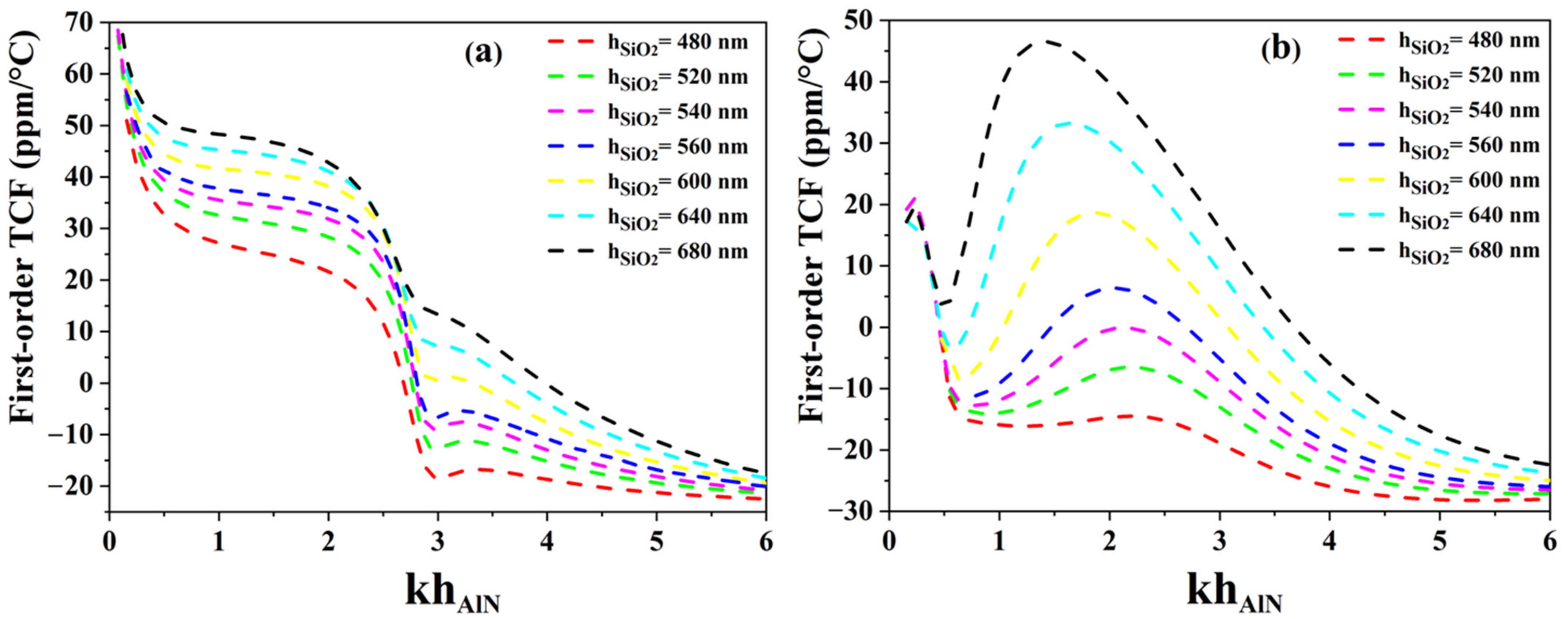
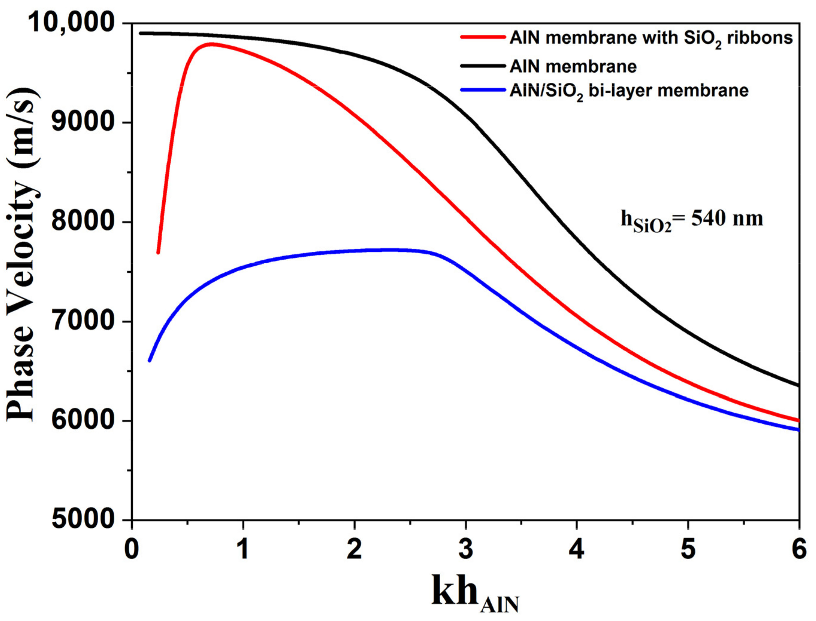
3.1. TCF and Phase Velocity in SiO2/AlN Structures

The temperature coefficient of frequency was first determined for AlN membranes equipped with either continuous SiO2 film or SiO2 ribbons, for various silicon dioxide thicknesses. As explained before, the width of the unit cells (corresponding to λ) has been set to 4 µm. Figure 2a shows the simulation results for both temperature compensation strategies. When continuous SiO2 films are introduced in the structure, the TCF dispersion curve shows a fast transition from positive TCF values to negative ones, leaving little room for temperature compensation. Then, Figure 2b clearly shows one, two or even three compensation points depending on the thickness of the SiO2 layer. We can also notice the existence of a plateau for relative AlN thicknesses (1.7 < khAlN < 2.4). For this design, the optimal SiO2 thickness would be 540 nm (relative thickness (khSiO2 = 0.85)).
As shown in Figure 3, the proposed implementation of structured SiO2 capping layers can strongly influence the dispersion curves and performances of such resonator structures, making it possible to adjust the boundary loads (including mass and electrical loads). This large dispersion of phase velocity is particularly visible for low relative AlN thicknesses (khAlN below 2.6). In this velocity domain, we noticed that the dispersion curve for the AlN membrane with SiO2 ribbons (red solid line) is positioned between those of SiO2/AlN bi-layer membrane (blue solid line), and AlN membrane (black solid line).
On the contrary, the TCF dispersion curve obtained for AlN membranes equipped with SiO2 ribbons (red solid line) makes it possible to have several compensation points, and gives the possibility of adjusting the SiO2 thickness in order to obtain a lower dependence on khAlN. This would offer more leeway for the design of sensors based on this structure, especially if an additional sensing layer has to be implemented in the structure. The corresponding AlN thicknesses would also be lower than for continuous AlN films, giving access to higher operating frequencies. In this case, the optimal SiO2 thickness for temperature compensation is 540 nm (khSiO2 = 0.85), which is also thinner than in the case of SiO2/AlN bi-layers.

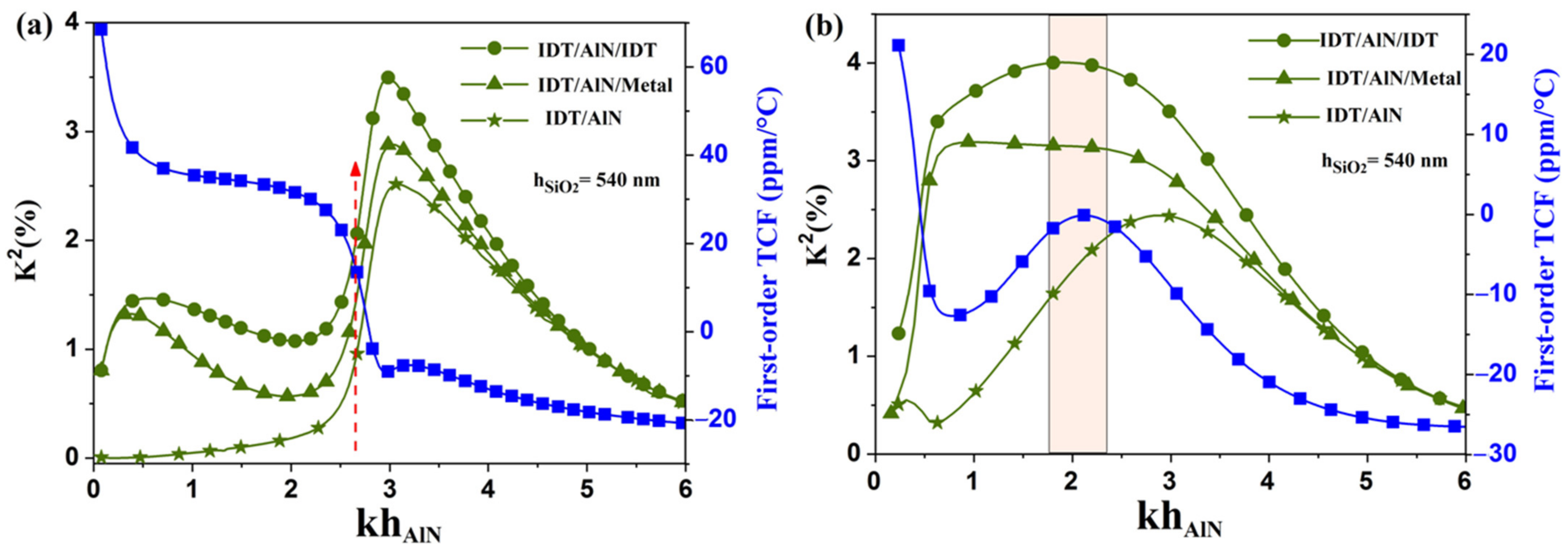
3.2. Electromechanical Coupling Coefficients in SiO2/AlN Structures

In this part of the work, the SiO2 layer thickness has been optimized in order to modify the shape of the dispersion curve, while avoiding the appearance of the stopband frequency. Dispersion curves and the K2 coefficient depend strongly on the sensitivity of the acoustic wave to the surface charge which can be identified by the difference in velocity of charged and uncharged surfaces. In the region where there is a maximum dispersion of velocity for which we can obtain optimal sensitivity, this region is equivalent to a maximum difference between phase velocity (vp) and group velocity (vg), i.e., vp–vg, with vg = ∂ω/∂k, k is the wavevector and ω the angular frequency. This hypothesis was mentioned by the authors in reference [44] associated with the propagation characteristics of Lamb waves in the AlN/Diamond bi-layer membrane. This property can be used to explain any change in the behavior of the K2 coefficient in both cases: the SiO2/AlN bi-layer structure and the AlN membrane with SiO2 ribbons. In the same way, we can explain the variation in TCF using the same hypothesis for both cases.
As shown before, another silicon dioxide thickness presents a strong interest in this study, this time for AlN membranes equipped with SiO2 ribbons: 540 nm (relative thickness of 0.85, for λ = 4 µm). Thus, similar dispersion curves have been generated for this SiO2 thickness, as shown in Figure 4, for both continuous silicon dioxide films and ribbons. As expected, the SiO2/AlN bi-layer membrane does not exhibit much leeway for TCF compensation, with a strong TCF variation in the neighborhood of the unique compensation point at about khAlN = 2.64 as shown in Figure 4a (red dotted up arrow). From these results, the electrode topology (IDT/AlN/IDT) reaches K2 of around 3% for the SiO2/AlN bi-layer membrane, whereas, for the other electrode topologies such as (IDT/AlN) and (IDT/AlN/Metal), they exhibit, respectively, K2 close to 1.3% and 2.2% for khAlN = 2.64 (Figure 4a).
As expected, the AlN membranes equipped with SiO2 ribbons benefit most from this SiO2 thickness. They exhibit good aptitudes for TCF compensation, and for relative AlN thicknesses (1.7 < khAlN < 2.4), while showing higher K2 coefficients, up to 3% and 4% for two electrode topologies: (IDT/AlN/Metal) and (IDT/AlN/IDT), respectively (see Figure 4b). Such a resonator structure leads to even higher K2 coefficients than with the previously proposed structures with 640 nm thick SiO2 ribbons [41]. It also keeps an edge in terms of design robustness, since both K2 and TCF share the same optimal AlN thickness (khAlN = 2.1), and remain rather steady around this value. The cell width is fixed to 4µm and the length and thickness of the SiO2 ribbons are fixed to 2 µm and 640 nm, respectively. There is no experience at this stage because unfortunately nowadays our team does not have the experimental means to carry out the manufacturing of AlN membranes.
We can explain the change in the electromechanical coupling coefficient for the three structural configurations by the fact that the interdigital transducers generate lateral and vertical electric fields in the AlN membrane. In addition, the membrane with SiO2 ribbons and IDT/AlN metal topology makes it possible to modify the distribution of the electric field: the vertical component becomes preponderant due to the low dielectric permittivity of SiO2 compared to that of the AlN membrane. The lateral electric component is very strong compared with the vertical electric component for high thicknesses. However, this topology presents a vertical electric component which becomes much larger than the lateral electric component for low thicknesses.

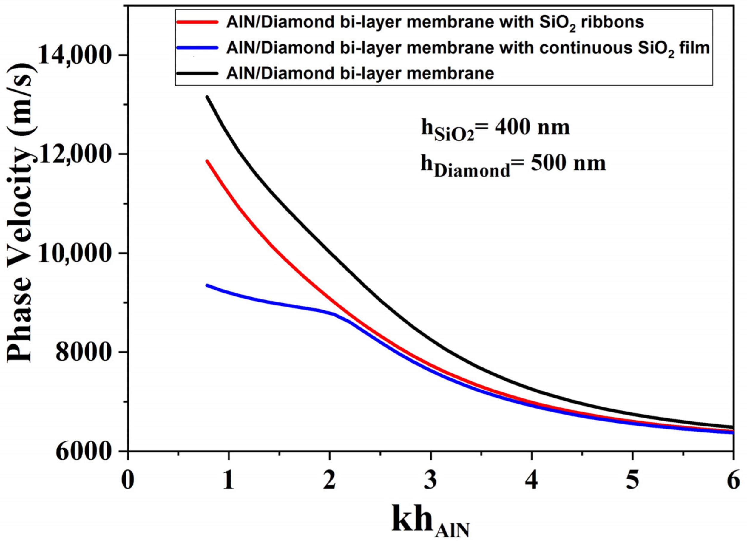
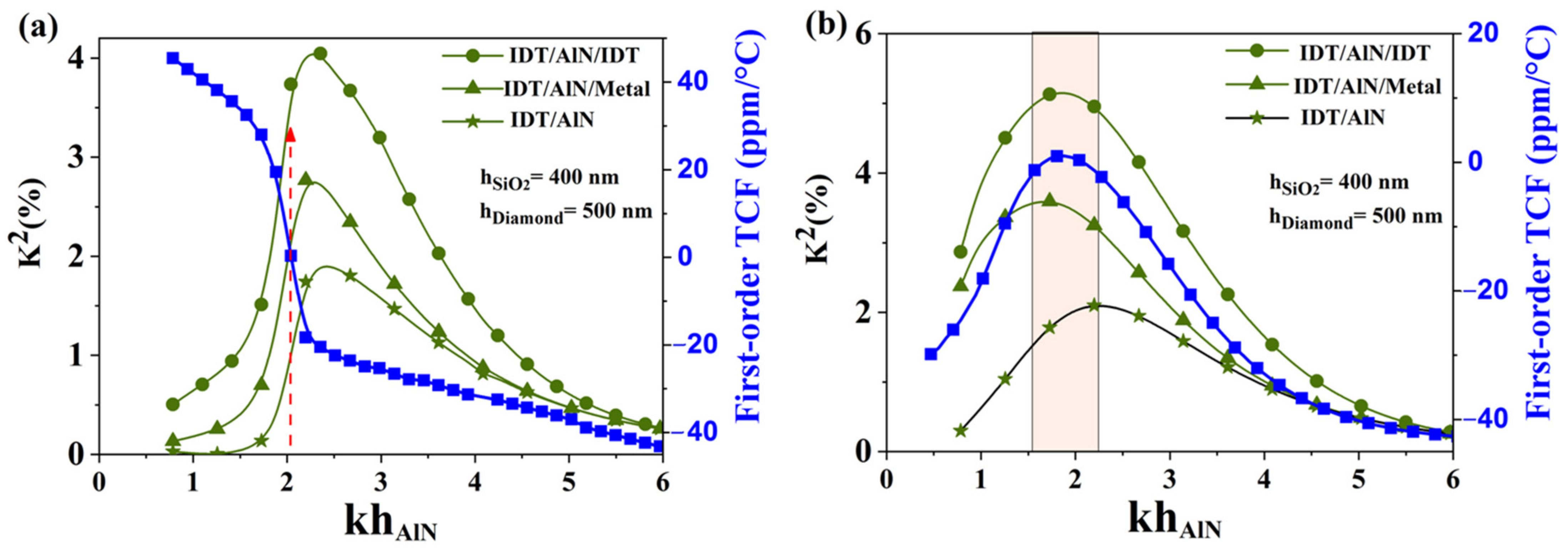
3.3. Phase Velocity in SiO2/AlN/Diamond Structures

The previously studied SiO2/AlN structures already exhibit strong performances in terms of TCF cancellation and electromechanical coupling. In this section, a diamond layer has been introduced underneath the previously studied resonator structures, in order to improve their high frequency performance. The various multilayer structures and their electrode topologies are summed up in Figure 5. As before, the IDTs’ electrical conductivity was neglected.
Similarly to the previous study of SiO2/AlN structures, the optimal thicknesses of SiO2 and diamond were determined in order to get a near-zero TCF plateau when using a ribbon-structured SiO2 layer. The chosen SiO2 thickness was 400 nm, while the diamond thickness was set to 500 nm. These values correspond to relative thicknesses of 0.6 and 0.75, respectively.
Figure 6 shows an increase in phase velocity when adding the diamond layer for both continuous and ribbon-like SiO2 film configurations. The AlN/Diamond bi-layer membrane with SiO2 ribbons (red solid line) shows a phase velocity close to 12000 m/s, which is larger than the velocities reached for SiO2/AlN/Diamond (blue solid line). We can also notice the dispersion curve of the structure equipped with ribbons (blue solid line) which approximates to the dispersion curve of the AlN/Diamond bi-layer membrane (black solid line).

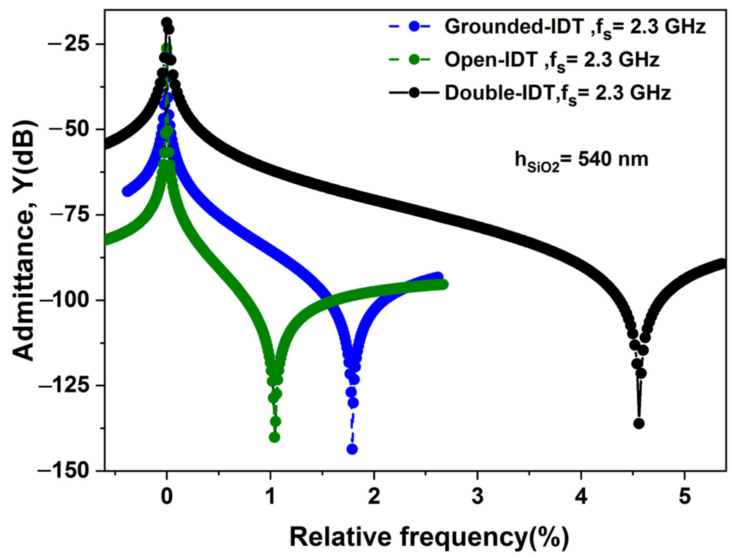
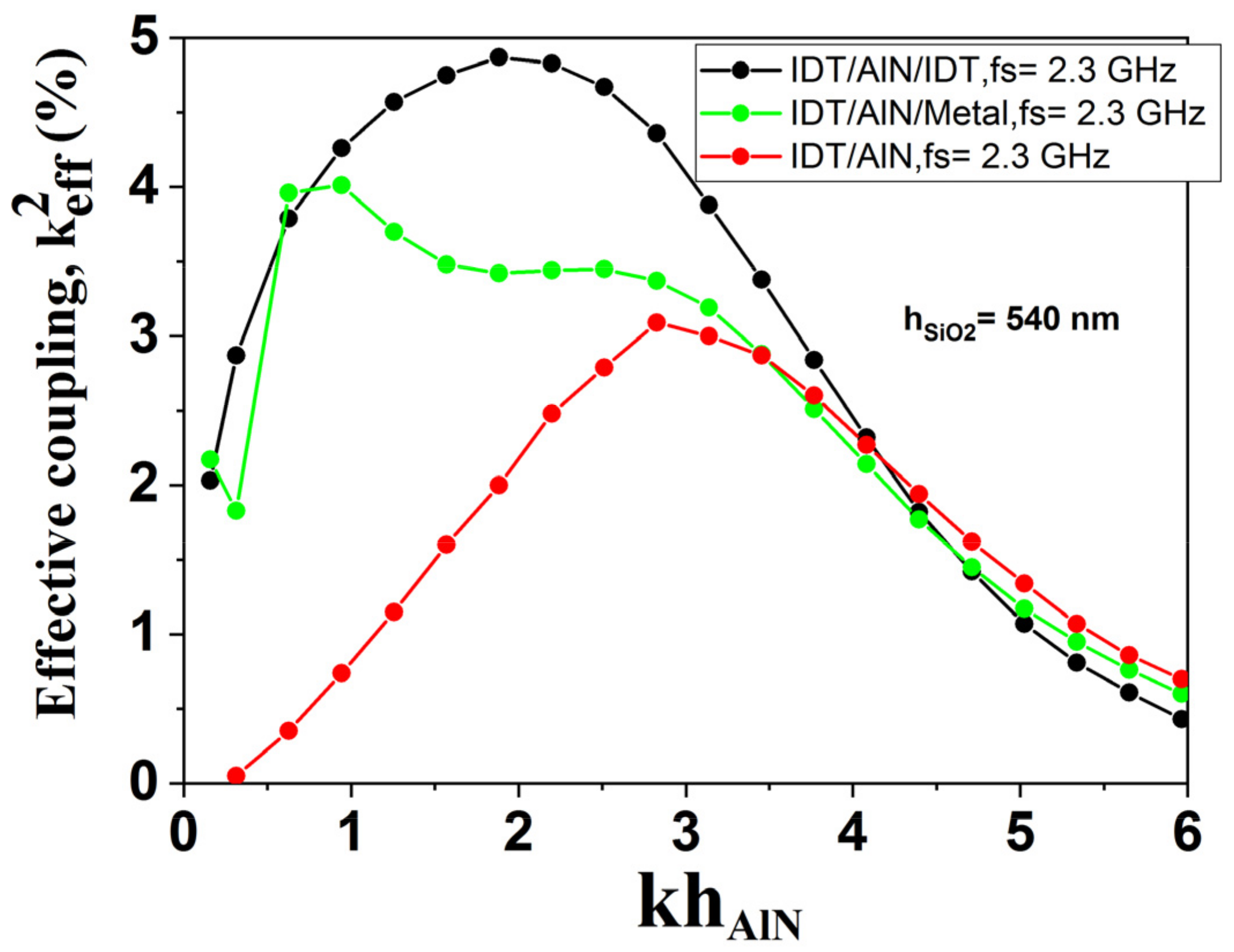
3.4. Electromechanical Coupling Coefficient of SiO2/AlN/Diamond Structures

In this section, the K2 and TCF coefficients of S0 Lamb-wave mode for the two layer configurations introduced previously were calculated: the first one corresponds to a multilayered structure of SiO2/AlN/Diamond, while the second one consists of an AlN/Diamond bi-layer structure equipped with SiO2 ribbons. The material constants of the diamond and the temperature coefficients used in the calculation are taken from the literature (See Table 1) [43]. Figure 7 presents the dispersion curves for K2 and TCF obtained from the simulations. One can see that SiO2/AlN/Diamond multilayered structures only offer one compensation point, for a relative thickness of 2.07 (red dotted up arrow). Moreover, the electrode topologies based on (IDT/AlN) only show residual electromechanical coupling with K2 coefficients close to 1%. The best electrode topology, based on (IDT/AlN/IDT), only exhibits a mild coupling coefficient of 3.7%.
Finally, as illustrated in Figure 7b, the addition of diamond underneath the AlN/SiO2 ribbons structure still enables TCF cancellation over a large range of relative AlN thickness (1.5 < khAlN < 2.32), similarly to the previously studied AlN/SiO2 ribbon structures. The presence of diamond offers even larger K2 coefficients, reaching 5.2% for the electrode topology (IDT/AlN/IDT), whereas for other electrode topologies such as (IDT/AlN) and (IDT/AlN/Metal), they exhibit, respectively, K2 close to 2% and 3.8% (Figure 7b).
In summary, these new structures benefit from the low permittivity of their additional diamond layer, compared to AlN. This changes the electric boundary conditions, and thus amplifies the gradient of the electric field in the AlN membrane. Consequently, the phase velocity could be increased, as well as the electromechanical coupling coefficient, leading to even more performant zero-TCF resonators. The TCF compensation would also be reached through a low khAlN of 2.07 (red dotted up arrow) for SiO2/AlN/Diamond multilayered structures, and even authorize a wide range of relative thickness when the SiO2 layer is structured into ribbons.
The proposed structures (Ribbon-Structured SiO2 Films to AlN-based and AlN/Diamond-based) can operate in the frequency domain around 2.3 GHz, with an electromechanical coupling coefficient close to 4% and 5.2%, phase velocity of 9200 and 9500 m/s, and a temperature coefficient of frequency close to 0 ppm/ °C.
We have summarized in Table 2 the advantages and the disadvantages for different device structures in the range of khAlN [0.6–2.6].
The calculation of the quality factor requires several geometric parameters of resonator, namely number of pairs of the IDT fingers, and the number of reflectors installed. In this work, we have taken into consideration only the mechanical energy loss from the resonator, knowing that the actual quality factor (Q) depends on different energy loss mechanisms.
As is well known, the effective coupling coefficient k eff 2 is defined by the approximation formula [45]:
k eff 2 = π 2 4 f p f s f p
where fp and fs are the parallel frequency and series frequency, respectively.
Figure 8 below shows the evolution of the admittance as a function of the relative frequency using an AlN membrane with SiO2 ribbons for three electrode topologies: IDT/AlN/Metal, IDT/AlN and IDT/AlN/IDT. One can see that the electrode topology IDT/AlN/IDT configuration presents a large effective coupling coefficient k eff 2   ≈ 4.9% compared to other electrode topologies.
Figure 9 shows the k eff 2 for three electrode topologies IDT/AlN/Metal, IDT/AlN and IDT/AlN/IDT using an AlN membrane with SiO2 ribbons of thickness hSiO2 = 540 nm. We noticed a similar behavior to that of K2 presented previously in the paper but with a slight increase in k eff 2 .
For the fabrication process of the AlN-based resonator, a 4 μm thick AlN layer is deposited by reactive sputtering on high-resistivity silicon wafers. The subsequent definition of the IDT is achieved through photolithography, with a bi-layer photoresist process (LOR 3A + AZ 1518). Then, an Al thin film (150 nm thick) is deposited by electron beam evaporation or thermal evaporation, followed by a lift-off process based on usual strippers, to free the top IDTs.

4. Conclusions

In this study, we have proposed new structured platforms for high-velocity, strong-coupling and zero-TCF resonators. In the first part, structures based on the association of AlN membranes and SiO2 ribbons covering the IDTs were proposed for use in S0-mode Lamb wave resonators. Such an AlN/SiO2 ribbon structure exhibits high phase velocity, and a large K2 (exceeding 4%). This structure can lead to good temperature compensation for an AlN thickness lower than in the case of a SiO2/AlN bi-layer membrane. In the second part, the addition of a diamond layer to the membrane structure was proposed, in order to reach even higher velocities and coupling coefficients. The lower permittivity of diamond helps to confine the electric field into the AlN layer, while its mechanical properties authorize larger velocities. The maximal free velocity in the membranes can thus be increased up to 12,000 m/s, while a coupling coefficient of 5.2% is predicted for the optimal structure, through a wide range of temperature compensation. The studied structures are also well suited for reliable operation at very high temperature, and thus pave the way towards radiofrequency devices and sensors withstanding harsh environments. Additionally, the outstanding mechanical properties of diamond makes it possible to improve the quality factor and the rigidity of the resonators.

Author Contributions

Conceptualization, A.T. and O.E.; methodology, M.M., O.E., E.H.E.B. and A.T.; resources, A.T.; data curation, M.M.; writing—original draft preparation, M.M.; writing—review and editing, O.E., E.H.E.B., J.S., O.M., P.P., O.B.M. and A.T.; supervision, O.E., E.H.E.B. and A.T. All authors have read and agreed to the published version of the manuscript.

Funding

This work was funded by the French National Research Agency (ANR) in the framework of ANR 20-CE42-0009 project. It is also supported by the CPER EE4.0 and IMETECH projects. The authors also thank RENATECH, the French national nanofabrication network.

Institutional Review Board Statement

Not applicable.

Informed Consent Statement

Not applicable.

Data Availability Statement

Not applicable.

Conflicts of Interest

The authors declare no conflict of interest.

References

  1. Hickernell, F.S. Surface acoustic wave devices: A rewarding past, a significant present and a promising future. In Proceedings of the 12th Conference on Microwaves and Radar, Krakow, Poland, 20–22 May 1998; p. 159. [Google Scholar] [CrossRef]
  2. Yamamoto, Y. SAW filters and resonators for public communication systems. In Proceedings of the IEEE Ultrasonics Symposium, Baltimore, MD, USA, 31 October–3 November 1993; p. 95. [Google Scholar] [CrossRef]
  3. Tominaga, T.; Takayanagi, S.; Yanagitani, T. c-Axis-tilted ScAlN films grown on silicon substrates for surface acoustic wave devices. Jpn. J. Appl. Phys. 2022, 61, SG1054. [Google Scholar] [CrossRef]
  4. Tsubouchi, K.; Sugai, K.; Mikoshina, N. AlN Material Constants Evaluation and SAW Properties on AlN/Al2O3 and AlN/Si. In Proceedings of the Ultrasonics Symposiums, Chicago, IL, USA, 14–16 October 1981; p. 375. [Google Scholar] [CrossRef]
  5. Nakahata, H.; Higaki, K.; Fujii, S.; Hachigo, A.; Kitabayashi, H.; Tanabe, K.; Seki, Y.; Shikata, S. SAW devices on diamond. In Proceedings of the IEEE Ultrasonics Symposium, Seattle, WA, USA, 7–10 November 1995; p. 361. [Google Scholar] [CrossRef]
  6. Lei, L.; Dong, B.; Hu, Y.; Lei, Y.; Wang, Z.; Ruan, S. High-Frequency Surface Acoustic Wave Resonator with Diamond/AlN/IDT/AlN/Diamond Multilayer Structure. Sensors 2022, 22, 6479. [Google Scholar] [CrossRef]
  7. Mortet, V.; Elmazria, O.; Nesladek, M.; Assouar, M.B.; Vanhoyland, G.; D’Haen, J.; D’Olieslaeger, M.; Alnot, P. Surface acoustic wave propagation in aluminum nitride-unpolished freestanding diamond structures. Appl. Phys. Lett. 2002, 81, 1720–1722. [Google Scholar] [CrossRef]
  8. Kirsch, P.; Assouar, M.B.; Elmazria, O.; Mortet, V.; Alnot, P. 5GHz SAW devices based on AlN/diamond layered structure realized using e-beam lithography. Appl. Phys. Lett. 2006, 88, 223504-1–223504-3. [Google Scholar] [CrossRef]
  9. Elmazria, O.; Zhgoon, S.; Le Brizoual, L.; Sarry, F.; Tsimbal, D.; Djouadi, M.A. AlN/ZnO/diamond structure combining isolated and surface acoustic waves. Appl. Phys. Lett. 2009, 95, 233503. [Google Scholar] [CrossRef]
  10. Rinaldi, M.; Zuniga, C.; Zuo, C.; Piazza, G. AlN contour-mode resonators for narrow-band filters above 3 GHz. In Proceedings of the IEEE International Frequency Control Symposium Joint with the 22nd European Frequency and Time Forum, Besancon, France, 20–24 April 2009; pp. 70–74. [Google Scholar] [CrossRef]
  11. Yantchev, V.; Katardjiev, I. Thin film Lamb wave resonators in frequency control and sensing applications: A review. J. Micromech. Microeng. 2013, 23, 043001. [Google Scholar] [CrossRef]
  12. Wingqvist, G.; Arapan, L.; Yantchev, V.; Katardjiev, I. A micromachined thermally compensated thin film Lamb wave resonator for frequency control and sensing applications. J. Micromech. Microeng. 2009, 19, 035018. [Google Scholar] [CrossRef]
  13. Li, C.; Liu, X.Z.; Peng, B.; Shu, L.; Li, Y.R. AlN-based surface acoustic wave resonators on platinum bottom electrodes for high-temperature sensing applications. Rare Met. 2016, 35, 408. [Google Scholar] [CrossRef]
  14. Dou, S.; Qi, M.; Chen, C.; Zhou, H.; Wang, Y.; Shang, Z.; Yang, J.; Wang, D.; Mu, X. High-temperature high-sensitivity AlN-on-SOI lamb wave resonant strain sensor. AIP Adv. 2018, 8, 065315. [Google Scholar] [CrossRef] [Green Version]
  15. Fan, S.; Wang, W.; Li, X.; Jia, Y.; Sun, Y.; Liu, M. Optimization of AIN Composite Structure Based Surface Acoustic Wave Device for Potential Sensing at Extremely High Temperature. Sensors 2020, 20, 4160. [Google Scholar] [CrossRef]
  16. Schmid, P.; Triendl, F.; Zarfl, C.; Schwarz, S.; Artner, W.; Schneider, M.; Schmid, U. Influence of the AlN/Pt-ratio on the electro-mechanical properties of multilayered AlN/Pt thin film strain gauges at high temperatures. Sens. Actuator A Phys. 2020, 302, 111805. [Google Scholar] [CrossRef]
  17. Arab, F.; Kanouni, F.; Serhane, R.; Pennec, Y.; Özer, Z.; Bouamama, K. Electro-Acoustic Properties of Scandium-Doped Aluminum Nitride (ScxAl1-xN) Material and its Application to Phononic Crystal-Coupled SAW Devices. Crystals 2022, 12, 1431. [Google Scholar] [CrossRef]
  18. Kimura, T.; Daimon, K.; Ogami, T.; Kadota, M. S0 Mode Lamb Wave Resonators Using LiNbO3 Thin Plate on Acoustic Multilayer Reflector. Jpn. J. Appl. Phys. 2013, 52, 07HD03. [Google Scholar] [CrossRef]
  19. Kadota, M.; Tanaka, S. Simulation of solidly mounted plate wave resonator with wide bandwidth using 0-th shear horizontal mode in LiNbO3 plate. Jpn. J. Appl. Phys. 2015, 54, 07HD09. [Google Scholar] [CrossRef]
  20. Qiu, L.; Li, X.; Matsuoka, N.; Omori, T.; Hashimoto, K.Y. Impact of Transverse Mode Resonances on Second Harmonic Generation in Radio-frequency Bulk Acoustic Wave Resonators. Jpn. J. Appl. Phys. 2019, 58, SGGC02. [Google Scholar] [CrossRef] [Green Version]
  21. Lin, C.-M.; Chen, Y.-Y.; Felmetsger, V.V.; Lien, W.-C.; Riekkinen, T.; Senesky, D.G.; Pisano, A.P. Surface acoustic wave on AlN/3C–SiC/Si multilayer structures. J. Micromech. Microeng. 2013, 23, 025019. [Google Scholar] [CrossRef]
  22. Wu, T.T.; Lin, C.M. Analysis of SFIT SAW filter using coupling of modes model. J. Chin. Inst. Eng. 2004, 27, 973. [Google Scholar] [CrossRef]
  23. Zhou, W. Thermal and dielectric properties of the AlN particles reinforced linear low-density polyethylene composites. Thermochim. Acta 2011, 512, 183–188. [Google Scholar] [CrossRef]
  24. Shelton, S.; Chan, M.L.; Park, H.; Horsle, D.; Boser, B.; Izyumin, I.; Przybyla, R.; Frey, T.; Judy, M.; Nunan, K.; et al. CMOS-compatible AlN piezoelectric micromachined ultrasonic transducers. In Proceedings of the 2009 IEEE International Ultrasonics Symposium, Rome, Italy, 20–23 September 2009. [Google Scholar] [CrossRef]
  25. Muhea, W.E.; Fida, M.; Sharma, A.; Avrutin, V.; Morkoc, H. Analytical model for schottky barrier height and threshold voltage of AlGaN/GaN HEMTs with piezoelectric effect. IEEE Trans. Electron Devices 2018, 65, 901–907. [Google Scholar] [CrossRef]
  26. Bhadwal, N.; Ben Mrad, R.; Behdinan, K. Review of Zinc Oxide Piezoelectric Nanogenerators: Piezoelectric Properties, Composite Structures and Power Output. Sensors 2023, 23, 3859. [Google Scholar] [CrossRef]
  27. Butt, Z.; Pasha, R.A.; Qayyum, F.; Anjum, Z.; Ahmad, N.; Elahi, H. Generation of electrical energy using lead zirconate titanate (PZT-5A) piezoelectric material: Analytical, numerical and experimental verifications. J. Mech. Sci. Technol. 2016, 30, 3553–3558. [Google Scholar] [CrossRef] [Green Version]
  28. Caliendo, C. Gigahertz-band electroacoustic devices based on AlN thick films sputtered on Al2O3 at low temperature. Appl. Phys. Lett. 2003, 83, 4851. [Google Scholar] [CrossRef]
  29. Aubert, T.; Bardong, J.; Legrani, O.; Elmazria, O.; Assouar, B.; Bruckner, G.; Talbi, A. In situ high-temperature characterization of AlN-based surface acoustic wave devices. J. Appl. Phys. 2013, 114, 014505. [Google Scholar] [CrossRef]
  30. Yen, T.-T.; Lin, C.-M.; Zhao, X.; Felmetsger, V.V.; Senesky, D.G.; Hopcroft, M.A.; Pisano, A.P. Characterization of aluminum nitride lamb wave resonators operating at 600 °C for harsh environment RF applications. In Proceedings of the IEEE International Conference on Micro Electro Mechanical Systems, MEMS, Hong Kong, China, 24–28 January 2010; p. 731. [Google Scholar] [CrossRef]
  31. Lin, C.; Chen, Y.; Pisano, A.P. Theoretical investigation of Lamb wave characteristics in AlN/3C–SiC composite membranes. Appl. Phys. Lett. 2010, 97, 193506. [Google Scholar] [CrossRef] [Green Version]
  32. Hoang, T.; Rey, P.; Vaudaine, M.-H.; Danel, J.-S.; Robert, P.; Benech, P.; Lemaitre-Auger, P. Temperature-compensated structure for SAW pressure sensor in very high temperature. In Proceedings of the 2007 IEEE International Frequency Control Symposium Joint with the 21st European Frequency and Time Forum, Geneva, Switzerland, 29 May–1 June 2007; p. 40. [Google Scholar] [CrossRef]
  33. Lin, C.-M.; Yen, T.-T.; Felmetsger, V.V.; Hopcroft, M.A.; Kuypers, J.H.; Pisano, A.P. Surface acoustic wave propagation properties in AlN/3C-SiC/Si composite structure. In Proceedings of the IEEE Ultrasonics Symposium, San Diego, CA, USA, 11–14 October 2010; p. 1696. [Google Scholar] [CrossRef]
  34. Lin, C.-M.; Yen, T.-T.; Felmetsger, V.V.; Hopcroft, M.A.; Kuypers, J.H.; Pisano, A.P. Thermally compensated aluminum nitride Lamb wave resonators for high temperature applications. Appl. Phys. Lett. 2010, 97, 083501. [Google Scholar] [CrossRef] [Green Version]
  35. Doppalapudi, D.; Mlcak, R.; LeClair, J.; Gwynne, P.; Bridgham, J.; Purchase, S.; Skelton, M.; Schultz, G.; Tuller, H. MEMS microresonators for high temperature sensor applications. MRS Online Proc. Libr. (OPL) 2010, 1222, 1222-DD01-02. [Google Scholar] [CrossRef]
  36. Bartoli, F.; Aubert, T.; Moutaouekkil, M.; Streque, J.; Pigeat, P.; Zhgoon, S.; Talbi, A.; Hage-Ali, S.; M’Jahed, H.; Elmazria, O. AlN/GaN/Sapphire heterostructure for high-temperature packageless acoustic wave devices. Sens. Actuator A Phys. 2018, 283, 9. [Google Scholar] [CrossRef]
  37. Qi, M.; Li, M.; Chen, Y.; Cheng, Y.; Zhang, S.; Cao, L.; Shang, Z.; Mu, X. AlScN-Based Dual-Mode Devices with Temperature Compensated Strategy and Process Optimization. IEEE Sens. J. 2022, 22, 24027. [Google Scholar] [CrossRef]
  38. Kuypers, J.H.; Lin, C.-M.; Vigevani, G.; Pisano, A.P. Intrinsic temperature compensation of aluminum nitride Lamb wave resonators for multiple-frequency references. In Proceedings of the IEEE International Frequency Control Symposium, Honolulu, HI, USA, 19–21 May 2008; p. 240. [Google Scholar] [CrossRef]
  39. Lin, C.-M.; Yen, T.-T.; Lai, Y.-J.; Felmetsger, V.V.; Hopcroft, M.A.; Kuypers, J.H.; Pisano, A.P. Temperature-compensated aluminum nitride Lamb wave resonators. IEEE Trans. Ultrason. Ferroelectr. Freq. Control 2010, 57, 524. [Google Scholar] [CrossRef]
  40. Zou, J.; Lin, C.-M.; Chen, Y.-Y.; Pisano, A.P. Theoretical study of thermally stable SiO2/AlN/SiO2 Lamb wave resonators at high temperatures. J. Appl. Phys. 2014, 115, 094510. [Google Scholar] [CrossRef]
  41. Moutaouekkil, M.; Elmazria, O.; Talbi, A.; Pernod, P.; Matar, O.B.; El Boudouti, E.H. Theoretical Study of Lamb wave mode S0 of AlN membrane bridges SiO2. In Proceedings of the IEEE International Ultrasonics Symposium (IUS), Washington, DC, USA, 6–9 September 2017; p. 1. [Google Scholar] [CrossRef]
  42. Bjurstrom, J.; Wingqvist, G.; Yantchev, V.; Katardjiev, I. Temperature compensation of liquid FBAR sensors. J. Micromech. Microeng. 2007, 17, 651. [Google Scholar] [CrossRef]
  43. Nakahata, H. Theoretical study on SAW characteristics of layered structures including a diamond layer. IEEE Trans. Ultrason. Ferroelectr. Freq. Control 1995, 42, 2. [Google Scholar] [CrossRef]
  44. Talbi, A.; Soltani, A.; Mortet, V.; Gerbedoen, J.-C.; De Jaeger, J.-C.; Pernod, P. Theoretical study of Lamb acoustic waves characteristics in a AlN/diamond composite membranes for super high frequency range operating devices. Diam. Relat. Mater. 2012, 22, 66. [Google Scholar] [CrossRef]
  45. Aigner, R. Bringing BAW technology into volume production: The ten commandments and the seven deadly sins. In Proceedings of the IEEE Symposium on Acoustic Wave, Devices for Future Mobile Communication Systems (IEEE, 2007), Chiba, Japan, 6–8 March 2007; pp. 85–91. [Google Scholar]
Figure 1. Illustration of the unit cells of the studied multilayered structures for three electrode topologies (AC): bilayer membrane with continuous SiO2 film on top (1) of the AlN, and AlN membrane equipped with SiO2 ribbons over the IDTs (2).
Sensors 23 06284 g001
Figure 2. Comparison of TCF dispersion curves for (a) SiO2/AlN bi-layer membrane and (b) AlN membrane equipped with SiO2 ribbons.
Sensors 23 06284 g002
Figure 3. Comparison of the phase velocity dispersion curves for AlN membrane (black solid line), SiO2/AlN bi-layer membrane (blue solid line), and AlN membrane with SiO2 ribbons (red solid line).
Sensors 23 06284 g003
Figure 4. Comparison of K2 and TCF dispersion curves for (a) SiO2/AlN bi-layer membrane, and (b) AlN membrane with SiO2 ribbons for hSiO2 = 540 nm. Green curves correspond to K2 coefficient and blue curve correspond to TCF.
Sensors 23 06284 g004
Figure 5. Illustration of the unit cells of the studied multilayered structures for three electrode topologies (AC): multilayer membrane with continuous SiO2 film on top (1) of the AlN/Diamond membrane, and AlN/Diamond bi-layer membrane equipped with SiO2 ribbons over the IDTs (2).
Sensors 23 06284 g005
Figure 6. Comparison of the phase velocity dispersion curves for AlN/Diamond bi-layer membrane with SiO2 ribbons (red solid line), SiO2/AlN/Diamond (blue solid line), and AlN/Diamond bi-layer membrane (black solid line).
Sensors 23 06284 g006
Figure 7. Comparison of K2 and TCF dispersion curves for (a) SiO2/AlN/Diamond multilayer membrane, and (b) AlN/Diamond bi-layer membrane with SiO2 ribbons for hSiO2 = 400 nm and hDiamond = 500 nm.
Sensors 23 06284 g007
Figure 8. Simulated evolution of the admittance as a function of the relative frequency for three electrode topologies: IDT/AlN/Metal, IDT/AlN and IDT/AlN/IDT for hSiO2 = 540 nm and KhAlN = 2.1.
Sensors 23 06284 g008
Figure 9. Simulated evolution of k eff 2 for three electrode topologies: IDT/AlN/Metal, IDT/AlN and IDT/AlN/IDT using AlN membrane with SiO2 ribbons of thickness hSiO2 = 540 nm.
Sensors 23 06284 g009
Table 1. Material parameters of AlN, SiO2 and diamond used in the calculations.
ConstantsSymbolAlN [42]SiO2 [42]Diamond [43]
Stiffness constant (GPa)C1134578.578.5
C1212516.116.1
C1312016.116.1
C3339578.578.5
C4411831.231.2
C6611031.231.2
Temperature coefficient of elasticTC11−0.372.39−0.14
Constant (10−4/°C)TC13−0.0185.84−0.57
TC33−0.652.39−0.14
TC44−0.51.51−0.125
Density (Kg/m3)ρ326022103510
Piezoelectric constant(C/m2)e15−0.48--
e31−0.58--
e331.55--
Temperature coefficient of mass densityTρ−14.69−1.65−3.6
(10−6/°C)
Dielectric constant (10−11F/m)ε1183.325.7
ε3393.325.7
Table 2. Advantages and disadvantages are observed in the range of khAlN [0.6–2.6] for different device structures.
Device StructureTransducer
Configurations
AdvantagesDisadvantages
SiO2/AlN bi-layer
membrane
electrode topologies (A)The fabrication process of continuous SiO2 film is a little simpler, the fabrication process of a single electrode is a little simplerlow phase velocity, bad temperature
stability
electrode topologies (B)The fabrication process of continuous SiO2 film is a little simplerlow phase velocity, bad temperature
stability, the fabrication process of the electrode is less difficult
electrode topologies (C)The fabrication process of continuous SiO2 film is a little simplerlow phase velocity, bad temperature
stability, the fabrication process of an IDT electrode is a little complicated
AlN membrane
with SiO2 ribbons
electrode topologies (A)high phase velocity, excellent temperature
stability, the fabrication process of a single electrode is a little simpler
electrode topologies (B)high phase velocity, excellent temperature
stability, K2 = 3%
The fabrication process of a metal electrode is less difficult
electrode topologies (C)high phase velocity, excellent temperature
stability, K2 = 4%
The fabrication process of IDT electrode is a little complicated
SiO2/AlN/Diamond
multilayer membrane
electrode topologies (A)The fabrication process of continuous SiO2 film is a little simpler, the fabrication process of a single electrode is a little simplerlow phase velocity, bad temperature
stability
electrode topologies (B)The fabrication process of continuous SiO2 film is a little simplerlow phase velocity, bad temperature
stability, the fabrication process of the electrode is less difficult
electrode topologies (C)The fabrication process of continuous SiO2 film is a little simplerlow phase velocity, bad temperature
stability, the fabrication process of an IDT electrode is a little complicated
SiO2/AlN/Diamond
with SiO2 ribbons
electrode topologies (A)high phase velocity, excellent temperature
stability, the fabrication process of a single electrode is a little simpler
electrode topologies (B)high phase velocity, excellent temperature
stability, K2 = 3.8%
The fabrication process of a metal electrode is less difficult
electrode topologies (C)high phase velocity, excellent temperature
stability, K2 = 5.2%
The fabrication process of an IDT electrode is a little complicated
Disclaimer/Publisher’s Note: The statements, opinions and data contained in all publications are solely those of the individual author(s) and contributor(s) and not of MDPI and/or the editor(s). MDPI and/or the editor(s) disclaim responsibility for any injury to people or property resulting from any ideas, methods, instructions or products referred to in the content.

