

Development of Real-Time Monitoring System Based on IoT Technology for Curing Compound Application Process during Cement Concrete Pavement Construction
Abstract
:1. Introduction
2. Development of Monitoring System of Curing Compound Spraying Amount
2.1. Selection of Flow Measurement Sensor
=Equipment speed (m/s) × Pavement width (m) × Standard spraying amount (L/m2)
=0.5 × 9.0 × 0.45 = 2.025 (L/s)
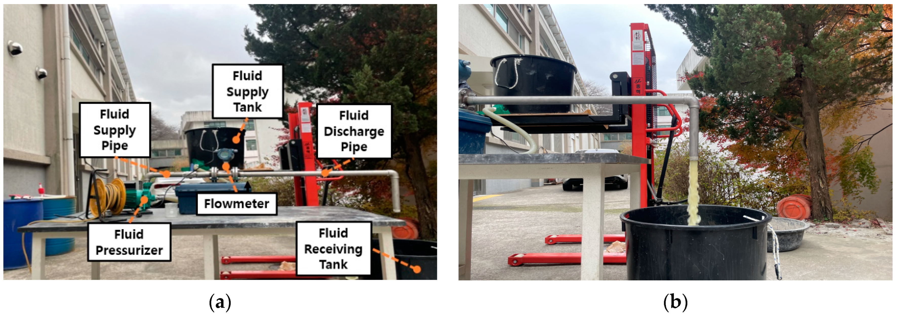
2.2. Accuracy Analysis of Flowmeter
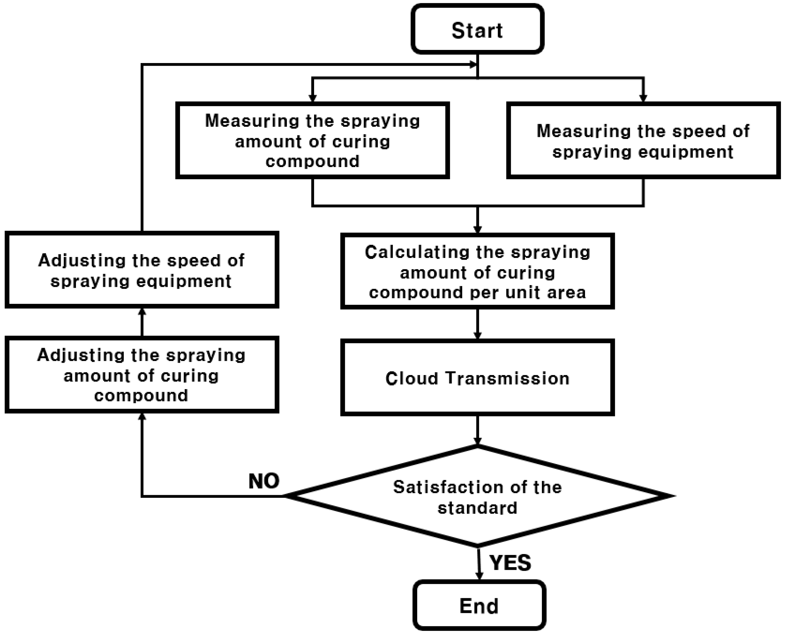
2.3. Algorithm of Curing Compound Spraying Amount Monitoring System
=Curing compound spraying amount (L)/(Moving distance of spraying equipment (m) × Pavement width (m))
3. Development of Monitoring System of Curing Compound Sprayed Status
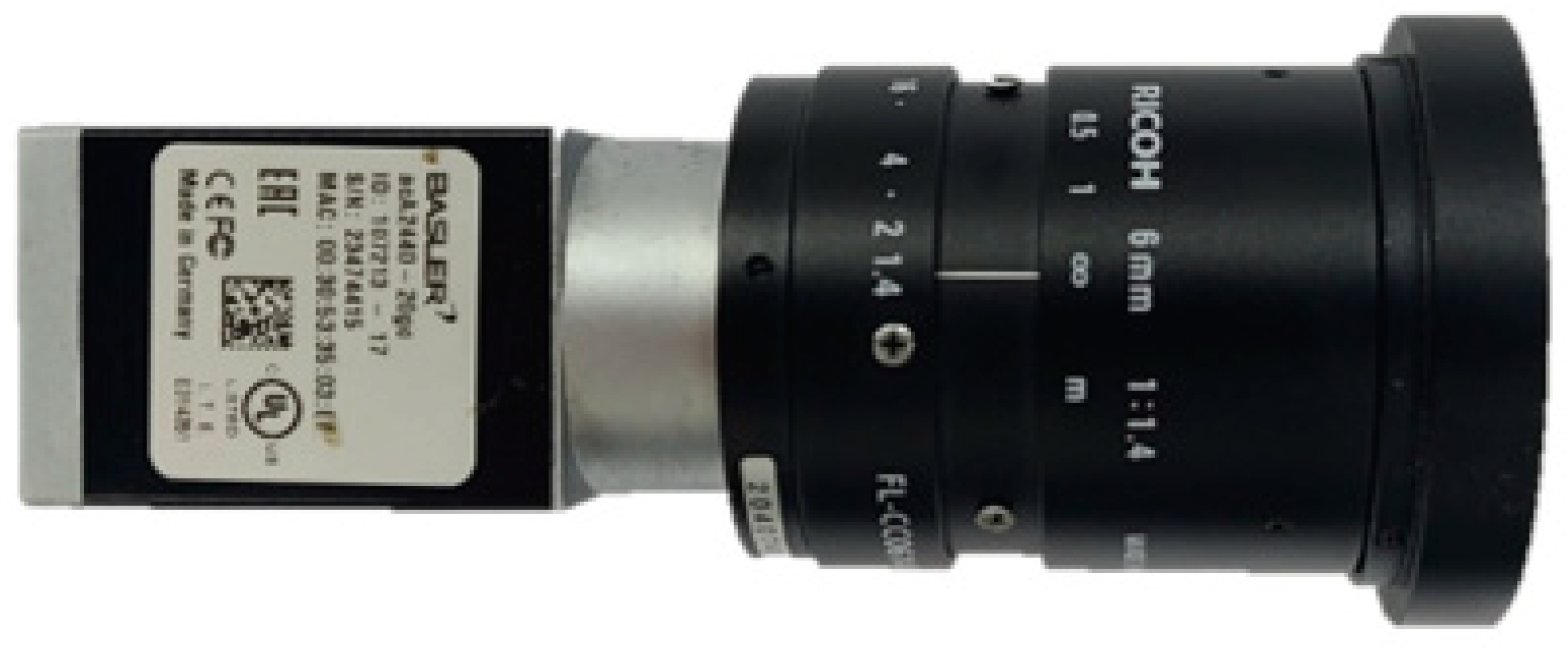
3.1. Selection of Image Acquisition Sensor
3.2. Image Analysis Program of Curing Compound Sprayed Status
3.3. Determination of Grayscale Reference of Curing Compound Sprayed Status
3.4. Algorithm of Curing Compound Sprayed Status Monitoring System
4. Feasibility In Situ Test
4.1. Analysis of Spraying Equipment Location and Speed
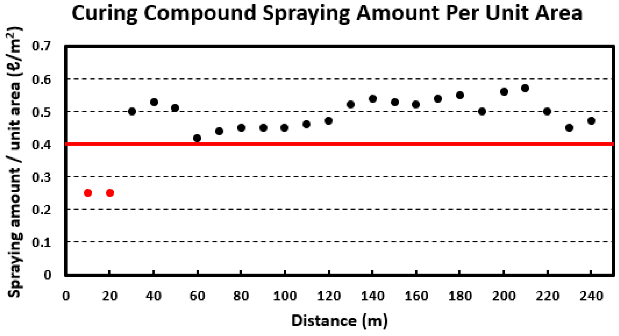
4.2. Analysis of Curing Compound Spraying Amount
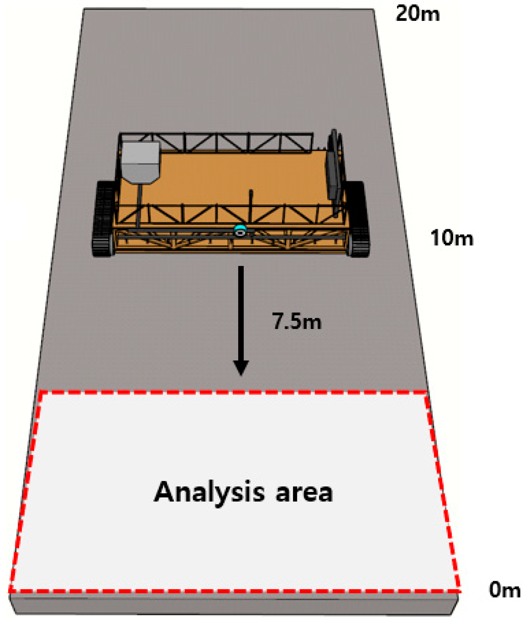
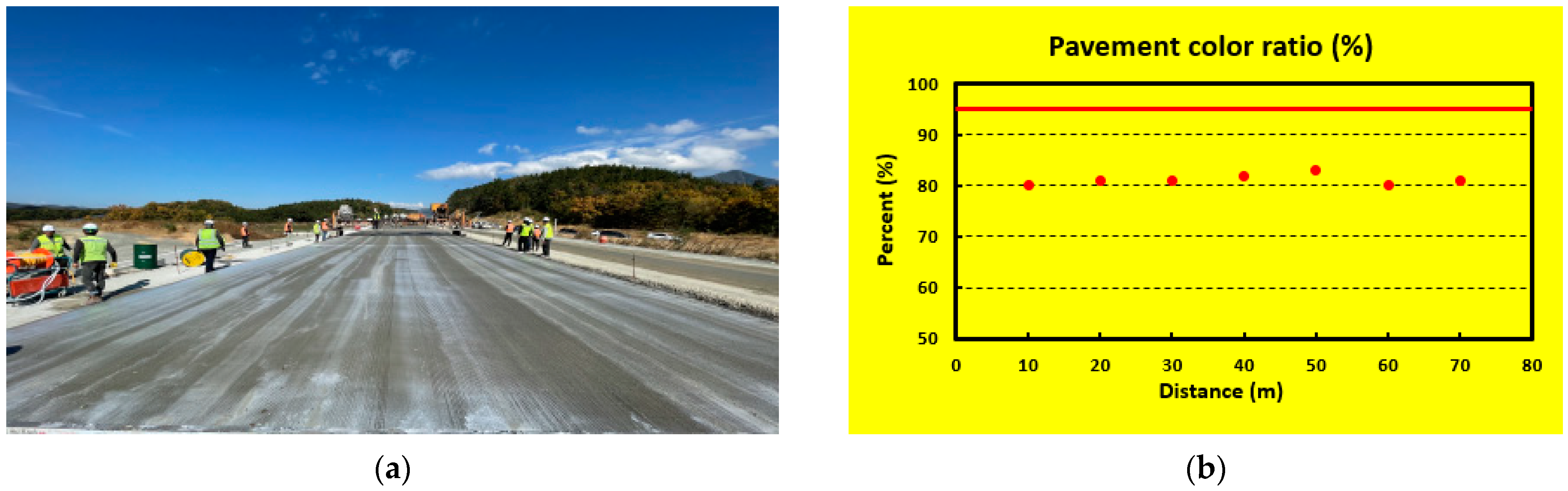
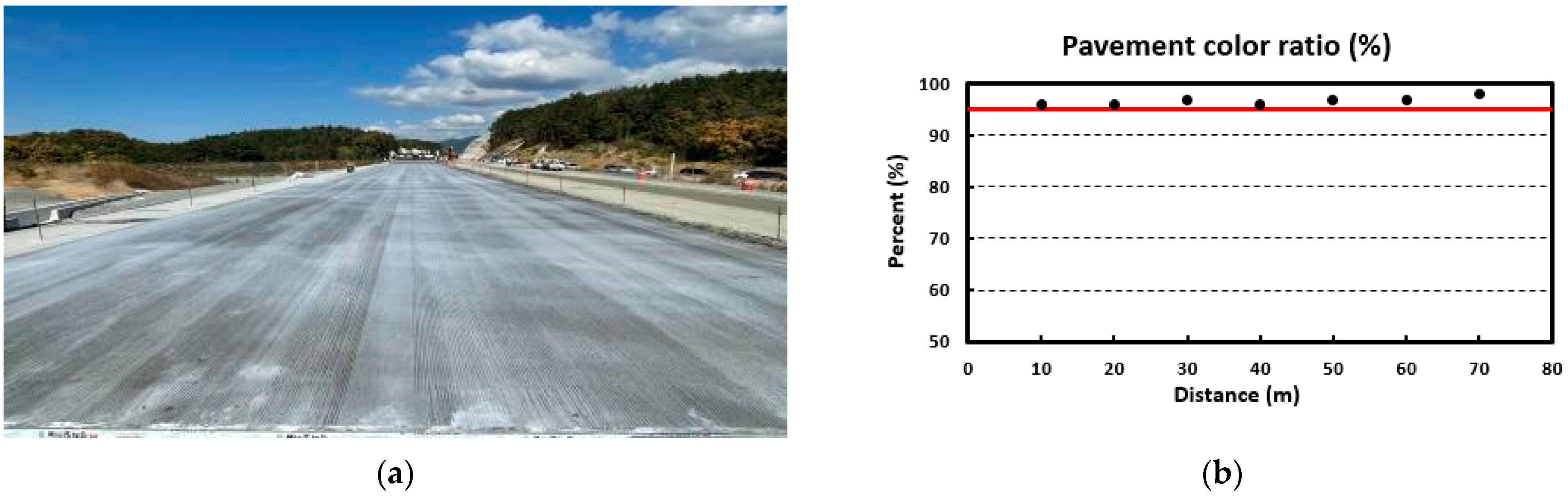
4.3. Analysis of Curing Compound Sprayed Status
5. Summary and Conclusions
- (1)
- We conduct a series of laboratory experiments to analyze the accuracy by selecting a flowmeter capable of measuring the curing compound spraying amount during concrete pavement construction and easy to transmit data in real time. As a result of the flow measurement accuracy test using water and curing compound, the accuracy is over 96%. Therefore, it is confirmed that the selected turbine flowmeter can be applied to measure the curing compound spraying amount in the field;
- (2)
- We select an image acquisition sensor for analyzing the curing compound sprayed status. The image sensor is able to interconnect the IP between the sensor and the personal computer, its output value is over 20 fps for the analysis of the sprayed status, and it can utilize gigabit Ethernet to make image processing more efficient;
- (3)
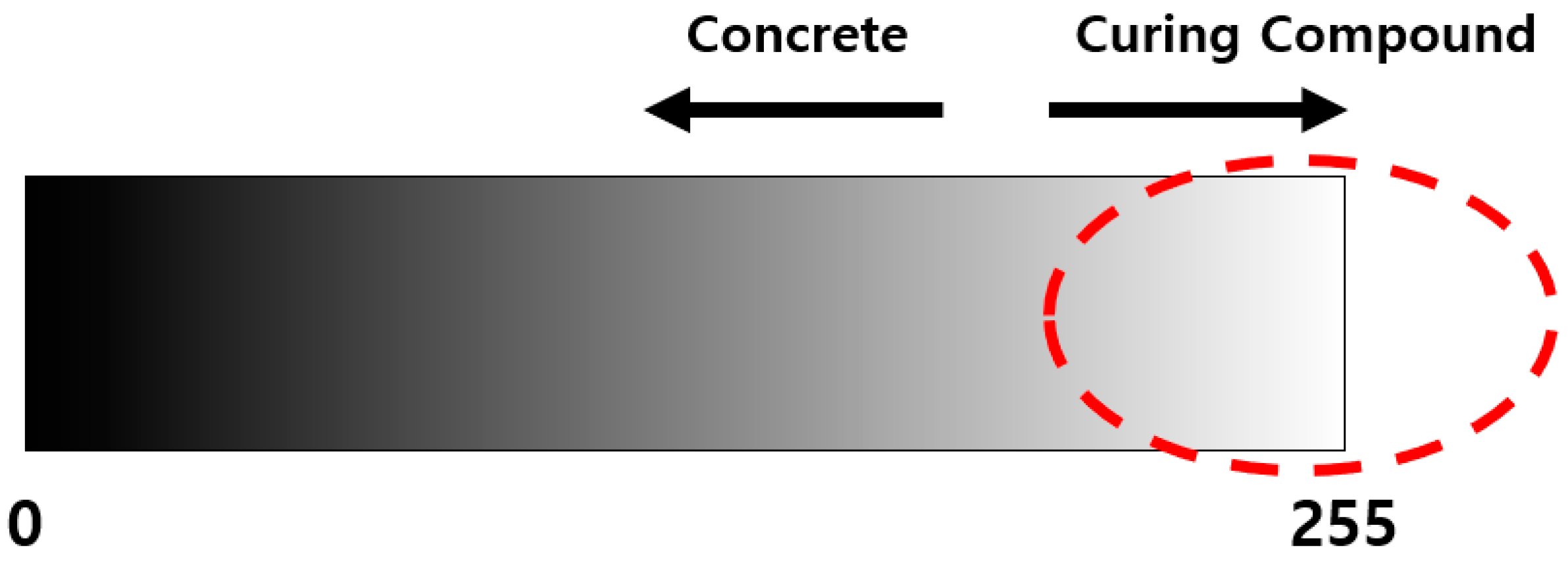
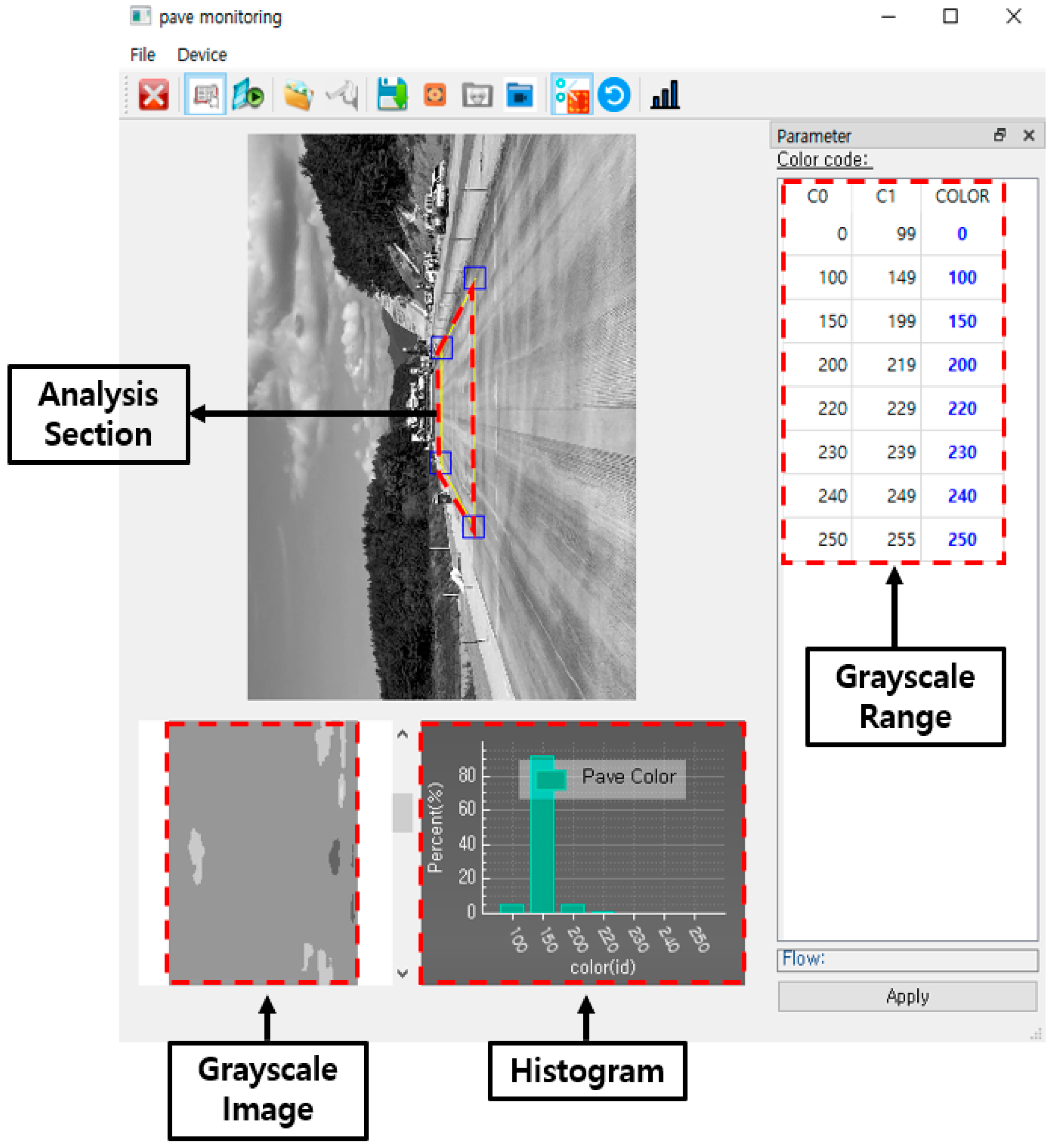
- To evaluate whether the curing compound is sprayed evenly, we develop an image processing program in this study that can convert the image of the curing compound sprayed status into grayscale and perform image clustering for analysis. The main function of the program is to convert the original image into grayscale, and the user can define the section to be analyzed. The image analysis results can be viewed as grayscale images, histograms, and tables, and analysis data can be saved in a CSV file format;
- (4)
- We perform laboratory experiments to select the reference grayscale range required for the analysis of the curing compound sprayed status. As a result, it is proposed to use a grayscale value of 185 in sunny weather and 170 in cloudy weather. However, these criteria are for reference only to users, and depending on the construction site conditions and environmental conditions, users can change and input a new grayscale reference value defined as the criterion for the appropriateness of the curing compound sprayed status into the program;
- (5)
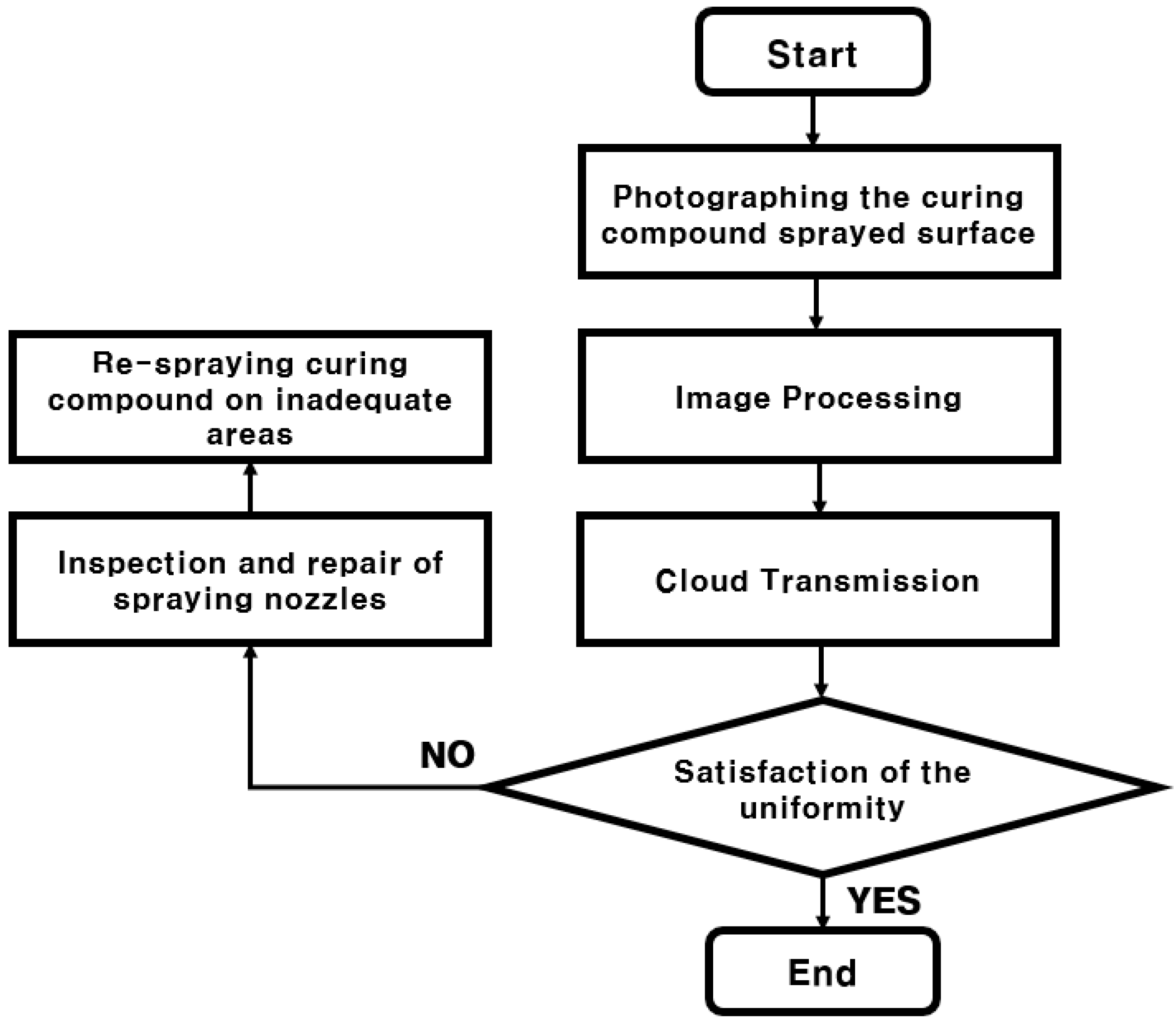
- We develop the algorithms for the curing compound spraying amount monitoring system and for the curing compound sprayed status monitoring system. In the curing compound spraying amount monitoring system, if it is evaluated that the curing compound spraying amount does not meet the standard, the curing compound spraying process can be calibrated in real time by adjusting the curing compound spraying amount or by adjusting the speed of the curing compound spraying equipment. In the curing compound sprayed status monitoring system, if it is evaluated that the curing compound sprayed status is uneven, the spray nozzles of the curing compound spraying equipment are checked and corrected, and the curing compound is re-sprayed in the section where the curing compound is not evenly sprayed;
- (6)
- In the curing compound spraying amount monitoring system and curing compound sprayed status monitoring system, various measured and analyzed values are transmitted to the IoT cloud and stored. These types of data include construction time, spraying equipment speed, equipment’s latitude, longitude and altitude, curing compound spraying rate, curing compound spraying amount, curing compound spraying amount per unit area, and ratio above the grayscale reference value of the curing compound sprayed status image. Through the cloud, it is possible to promote quality control by providing measurement and analysis data to construction personnel in real time;
- (7)
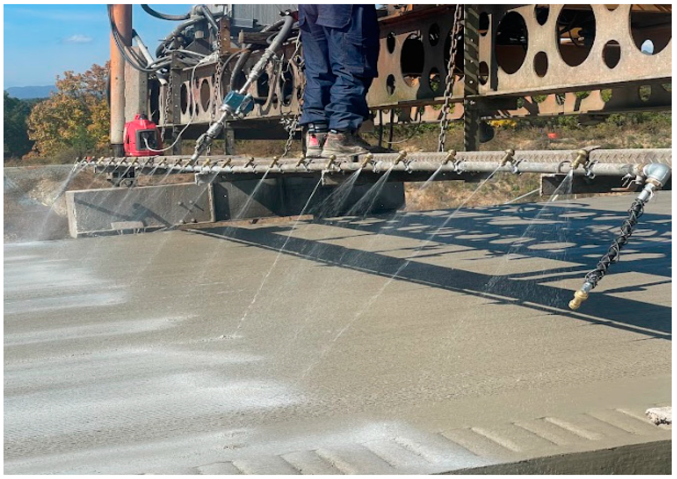
- We conduct the field experiment to confirm the field applicability of the developed IoT-based curing compound spraying amount monitoring system. Based on the data transmitted to the IoT cloud in the field experiment, the location and speed of the curing compound spraying equipment can be properly analyzed as the spraying equipment moves. It is also confirmed that it is possible to evaluate in real time whether the curing compound spraying amount per unit area is appropriate to the standard;
- (8)
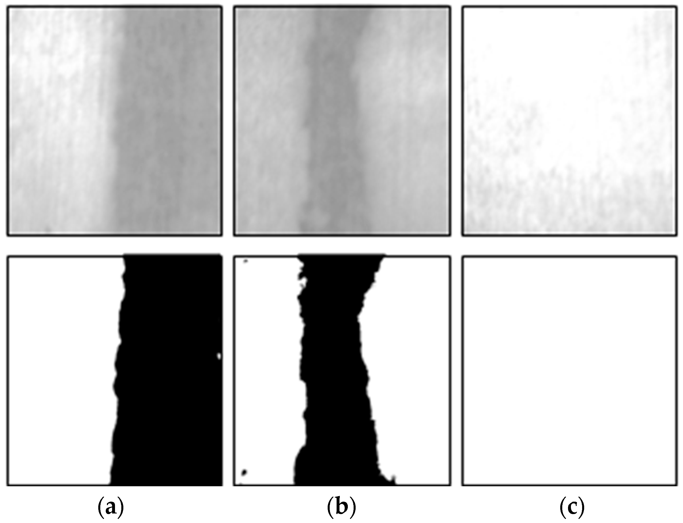
- We conduct the field experiment to confirm the field applicability of the developed IoT-based curing compound sprayed status monitoring system. For the experiment, firstly, the amount of spraying from each spray nozzle is changed so that the curing compound sprayed status is not uniform. And then we perform the experiment a second time by re-spraying the curing compound after maintaining the spray nozzle so that the curing compound sprayed status is more uniform. It is confirmed that when the curing compound sprayed status is not uniform and does not satisfy the grayscale standard range, the user’s screen is changed to yellow, and an alarm is immediately delivered to the user. It is also confirmed that when the curing compound sprayed status is uniform, it is properly evaluated.
Author Contributions
Funding
Institutional Review Board Statement
Data Availability Statement
Conflicts of Interest
References
- Ministry of Land, Infrastructure and Transport. Cement Concrete Pavement Construction Guidelines; Ministry of Land, Infrastructure and Transport: Sejong, Republic of Korea, 2017. [Google Scholar]
- Ministry of Land, Infrastructure and Transport. Korean Construction Specification (KCS) 44 50 15 Cement Concrete Pavement Construction; Ministry of Land, Infrastructure and Transport: Sejong, Republic of Korea, 2023. [Google Scholar]
- Highways England. Specification for Highway Works (MCHW 1); Highways England: Bristol, UK, 2021. [Google Scholar]
- Austroads. Guide to Pavement Technology Part 8: Pavement Construction; Austroads: Sydney, NSW, Australia, 2019. [Google Scholar]
- Kanto Regional Development Bureau, Ministry of Land, Infrastructure, Transport and Tourism. Kanto Regional Development Bureau Public Works Common Specifications; Kanto Regional Development Bureau, Ministry of Land, Infrastructure, Transport and Tourism: Tokyo, Japan, 2020. [Google Scholar]
- Arizona Department of Transportation. Standard Specifications for Road and Bridge Construction; Arizona Department of Transportation: Phoenix, AZ, USA, 2021. [Google Scholar]
- Florida Department of Transportation. Standard Specifications for Road and Bridge Construction; Florida Department of Transportation: Tallahassee, FL, USA, 2023. [Google Scholar]
- Illinois Department of Transportation. Standard Specifications for Road and Bridge Construction; Illinois Department of Transportation: Springfield, IL, USA, 2022. [Google Scholar]
- Kentucky Transportation Cabinet. Division 500 PCC Pavement and Non-Structural Concrete Construction; Kentucky Transportation Cabinet: Frankfort, KY, USA, 2019. [Google Scholar]
- Louisiana Department of Transportation and Development. Louisiana Standard Specifications for Roads and Bridges; Louisiana Department of Transportation and Development: Baton Rouge, LA, USA, 2016. [Google Scholar]
- Michigan Department of Transportation. Standard Specifications for Construction; Michigan Department of Transportation: Lansing, MI, USA, 2020. [Google Scholar]
- Mississippi Department of Transportation. Mississippi Standard Specifications for Road and Bridge Construction; Mississippi Department of Transportation: Jackson, MS, USA, 2017. [Google Scholar]
- New York State of Opportunity Department of Transportation. Standard Specifications (USC); New York State of Opportunity Department of Transportation: New York, NY, USA, 2023. [Google Scholar]
- North Carolina Department of Transportation. Standard Specifications for Road and Structures; North Carolina Department of Transportation: Raleigh, NC, USA, 2018. [Google Scholar]
- Texas Department of Transportation. Standard Specifications for Construction and Maintenance of Highways, Streets, and Bridges; Texas Department of Transportation: Austin, TX, USA, 2014. [Google Scholar]
- Utah Department of Transportation. Standard Specifications for Road and Bridge Construction; Utah Department of Transportation: Taylorsville, UT, USA, 2022. [Google Scholar]
- Virginia Department of Transportation. Concrete Pocket Guide; Virginia Department of Transportation: Richmond, VA, USA, 2022. [Google Scholar]
- Washington State Department of Transportation. Standard Specifications for Road, Bridge, and Municipal Construction M 41-10; Washington State Department of Transportation: Olympia, WA, USA, 2018. [Google Scholar]
- Pawar, Y.; Kate, S. Curing of concrete: A review. Int. Res. J. Eng. Technol. 2020, 7, 1820–1824. [Google Scholar]
- Ye, D.; Zollinger, D.; Choi, S.; Won, M. Literature Review of Curing in Portland Cement Concrete Pavement; Technical Report, Nr. FHWA/TX06/0-5106-1; National Academies: Washington, DC, USA, 2006. [Google Scholar]
- Jeong, J.-H.; Zollinger, D.G. Development of test methodology and model for evaluation of curing effectiveness in concrete pavement construction. Transp. Res. Rec. 2003, 1861, 17–25. [Google Scholar] [CrossRef]
- Joshaghani, A.; Zollinger, D.G. Concrete pavements curing evaluation with non-destructive tests. Constr. Build. Mater. 2017, 154, 1250–1262. [Google Scholar] [CrossRef]
- Joshaghani, A.; Zollinger, D.G. Evaluating the quality of curing applications on concrete pavements with ground-penetrating radar. Transp. Res. Rec. 2021, 2675, 106–120. [Google Scholar] [CrossRef]
- Sun, P. A New Protocol for Evaluating Concrete Curing Effectiveness. Master’s Thesis, Texas A&M University, College Station, TX, USA, 2013. [Google Scholar]
- Joshaghani, A.; Bhardwaj, R.; Zollinger, D.G.; Mukhopadhyay, A.K. Investigating the effects of curing quality on key concrete pavement surface properties. Transp. Res. Rec. 2019, 2673, 71–80. [Google Scholar] [CrossRef]
- Wang, K.; Cable, J.K.; Ge, Z. Evaluation of pavement curing effectiveness and curing effects on concrete properties. J. Mater. Civ. Eng. 2006, 18, 377–389. [Google Scholar] [CrossRef]
- Ye, D.; Shon, C.-S.; Mukhopadhyay, A.K.; Zollinger, D.G. New performance-based approach to ensure quality curing during construction. J. Mater. Civ. Eng. 2010, 22, 687–695. [Google Scholar] [CrossRef]
- Tiznobaik, M.; Bassuoni, M. Application of curing compounds on concrete pavements. Can. J. Civ. Eng. 2017, 44, 452–461. [Google Scholar] [CrossRef]
- Whiting, N.M.; Snyder, M.B. Effectiveness of Portland cement concrete curing compounds. Transp. Res. Rec. 2003, 1834, 59–68. [Google Scholar] [CrossRef]
- Tiznobaik, M.; Bassuoni, M.; Peters, M.B. Curing efficiency of three different curing compound applications to concrete pavements. GEN 2015, 56, 1. [Google Scholar]
- Hajibabaee, A.; Khanzadeh Moradllo, M.; Ley, M.T. Comparison of curing compounds to reduce volume change from differential drying in concrete pavement. Int. J. Pavement Eng. 2018, 19, 815–824. [Google Scholar] [CrossRef]
- Xue, B.; Pei, J.; Sheng, Y.; Li, R. Effect of curing compounds on the properties and microstructure of cement concretes. Constr. Build. Mater. 2015, 101, 410–416. [Google Scholar] [CrossRef]
- Zhou, L. Highway Road Widening Construction Technology Based on Short-Distance Sensing Technology. In Proceedings of the 2021 Fifth International Conference on I-SMAC (IoT in Social, Mobile, Analytics and Cloud) (I-SMAC), Palladam, India, 11–13 November 2021; pp. 1718–1721. [Google Scholar]
- Mohamed, M.; Tran, D.Q. Content analysis of e-inspection implementation for highway infrastructure construction projects. Eng. Constr. Archit. Manag. 2023, 30, 2621–2644. [Google Scholar] [CrossRef]
- Ogunrinde, O.; Nnaji, C.; Amirkhanian, A. Quality management technologies in highway construction: Stakeholders’ perception of utility, benefits, and barriers. Pract. Period. Struct. Des. Constr. 2021, 26, 04020043. [Google Scholar] [CrossRef]
- Radziszewski, P.; Nazarko, J.; Vilutiene, T.; Dębkowska, K.; Ejdys, J.; Gudanowska, A.; Halicka, K.; Kilon, J.; Kononiuk, A.; Kowalski, K.J. Future trends in road technologies development in the context of environmental protection. Balt. J. Road Bridge Eng. 2016, 11, 160–168. [Google Scholar] [CrossRef]
- Zhang, J.; Zhu, Z.; Liu, H.; Zuo, J.; Ke, Y.; Philbin, S.P.; Zhou, Z.; Feng, Y.; Ni, Q. System Framework for Digital Monitoring of the Construction of Asphalt Concrete Pavement Based on IoT, BeiDou Navigation System, and 5G Technology. Buildings 2023, 13, 503. [Google Scholar] [CrossRef]
- Sharif, M.; Jacobs, G.; Van Den Bergh, W.; Hellinckx, P. IT in road construction: Recommendations for the development of production, transport and paving data storage in the Flemish region. In Proceedings of the 2018 2nd International Conference on Big Data and Internet of Things, Beijing, China, 24–26 October 2018; pp. 143–147. [Google Scholar]
- Ma, Z.; Zhang, J.; Philbin, S.P.; Li, H.; Yang, J.; Feng, Y.; Ballesteros-Pérez, P.; Skitmore, M. Dynamic quality monitoring system to assess the quality of asphalt concrete pavement. Buildings 2021, 11, 577. [Google Scholar] [CrossRef]
- Zhang, C.; Zheng, Y. Study on the Evaluation Standard of Construction Quality for Asphalt Pavement Based on the Intelligent Sensing Aggregate. Adv. Civ. Eng. 2021, 2021, 9985627. [Google Scholar] [CrossRef]
- Kuenzel, R.; Teizer, J.; Mueller, M.; Blickle, A. SmartSite: Intelligent and autonomous environments, machinery, and processes to realize smart road construction projects. Autom. Constr. 2016, 71, 21–33. [Google Scholar] [CrossRef]
- Wang, X.; Shen, S.; Huang, H.; Zhang, Z. Towards smart compaction: Particle movement characteristics from laboratory to the field. Constr. Build. Mater. 2019, 218, 323–332. [Google Scholar] [CrossRef]
- Zhu, S.; Li, X.; Wang, H.; Yu, D. Development of an automated remote asphalt paving quality control system. Transp. Res. Rec. 2018, 2672, 28–39. [Google Scholar] [CrossRef]
- Wang, S.; Zhao, S.; Al-Qadi, I.L. Real-time monitoring of asphalt concrete pavement density during construction using ground penetrating radar: Theory to practice. Transp. Res. Rec. 2019, 2673, 329–338. [Google Scholar] [CrossRef]
- Zhang, L.; Shi, Y.; Zhao, Z.; Zhang, P. Real-Time Monitoring System and Evaluation Method of Asphalt Pavement Paving Temperature Segregation. In Proceedings of the Transportation Research Congress 2016, Beijing, China, 6–8 June 2016; pp. 383–395. [Google Scholar]
- Ma, Y.; Chen, F.; Ma, T.; Huang, X.; Zhang, Y. Intelligent compaction: An improved quality monitoring and control of asphalt pavement construction technology. IEEE Trans. Intell. Transp. Syst. 2021, 23, 14875–14882. [Google Scholar] [CrossRef]
- Xu, Q.; Chang, G.K. Evaluation of intelligent compaction for asphalt materials. Autom. Constr. 2013, 30, 104–112. [Google Scholar] [CrossRef]
- Xu, Q.; Chang, G.K.; Gallivan, V.L. Development of a systematic method for intelligent compaction data analysis and management. Constr. Build. Mater. 2012, 37, 470–480. [Google Scholar] [CrossRef]
- John, S.T.; Philip, M.S.; Agarwal, S.; Sarkar, P.; Davis, R. IoT-Enabled Real-Time Monitoring System for Plastic Shrinkage of Concrete. J. Infrastruct. Syst. 2023, 29, 06023001. [Google Scholar] [CrossRef]
- Hou, Z.Y.; Peng, P.; Xie, J.D.; Zheng, S.P.; Yuan, Y.Z. Study on Test Methods for Intelligence-Based Monitoring of Fresh Cement Concrete Quality. Adv. Mater. Res. 2014, 857, 3–9. [Google Scholar] [CrossRef]
- Skalecki, P.; Rechkemmer, S.; Sawodny, O. Process and data modeling for system integration–towards smart concrete pavement construction. In Proceedings of the 2020 IEEE/SICE International Symposium on System Integration (SII), Honolulu, HI, USA, 12–15 January 2020; pp. 1248–1253. [Google Scholar]
- Liu, D.; Wu, Y.; Li, S.; Sun, Y. A real-time monitoring system for lift-thickness control in highway construction. Autom. Constr. 2016, 63, 27–36. [Google Scholar] [CrossRef]
- Choi, S.; Yeon, J.H.; Won, M.C. Improvements of curing operations for Portland cement concrete pavement. Constr. Build. Mater. 2012, 35, 597–604. [Google Scholar] [CrossRef]
- FLOW Digital. User’s Manual for TFM Series; FLOW Digital: Singapore, 2020. [Google Scholar]
- BASLER. User’s Manual for GigE Cameras; BASLER: Ahrensburg, Germany, 2016. [Google Scholar]
- RICOH. New Megapixel Lenses for Machine Vision; RICOH: Ota City, Japan, 2015. [Google Scholar]


| Country/State | Curing Compound Application Rate (L/m2) |
|---|---|
| Korea | 0.4~0.5 |
| United Kingdom | 0.22 |
| Australia | 0.4 |
| Japan | 0.1~0.2 |
| Arizona | 0.41 |
| Florida | 0.27 |
| Illinois | 0.32 |
| Kentucky | 0.34 |
| Louisiana | 0.41 |
| Michigan | 0.36 |
| Mississippi | 0.27 |
| New York | 0.27 |
| North Carolina | 0.27 |
| Texas | 0.46 |
| Utah | 0.41 |
| Virginia | 0.27~0.41 |
| Washington | 0.27 |
| Case | Measured Flow Speed (L/s) | Calculated Volume of Water (L) | Measured Volume of Water in Tank (L) | Accuracy (%) |
|---|---|---|---|---|
| 1 | 3.62 | 36.2 | 37.5 | 96.5 |
| 2 | 2.53 | 25.3 | 26.2 | 96.6 |
| 3 | 1.51 | 15.1 | 15.7 | 96.2 |
| 4 | 0.79 | 7.9 | 7.6 | 96.1 |
| Average accuracy (%) | 96.4 | |||
| Case | Measured Flow Speed (L/s) | Calculated Volume of Curing Compound (L) | Measured Weight of Curing Compound in Tank (kg) | Converted Volume of Curing Compound (L) | Accuracy (%) |
|---|---|---|---|---|---|
| 1 | 3.64 | 36.4 | 31.8 | 37.0 | 98.4 |
| 2 | 2.50 | 25.0 | 22.3 | 25.9 | 96.4 |
| 3 | 1.54 | 15.4 | 13.6 | 15.8 | 97.4 |
| 4 | 0.78 | 7.8 | 7.1 | 8.3 | 94.5 |
| Average accuracy (%) | 96.7 | ||||
| No. | Area | Specimen of Sprayed Area of 50% | Specimen of Sprayed Area of 66% | Specimen of Sprayed Area of 100% |
|---|---|---|---|---|
| 1 | Not sprayed concrete surface | 0~190 | 0~190 | 0~190 |
| Curing compound sprayedconcrete surface | 191~255 | 191~255 | 191~255 | |
| 2 | Not sprayed concrete surface | 0~184 | 0~181 | 0~184 |
| Curing compound sprayedconcrete surface | 185~255 | 182~255 | 185~255 | |
| 3 | Not sprayed concrete surface | 0~190 | 0~190 | 0~190 |
| Curing compound sprayedconcrete surface | 191~255 | 191~255 | 191~255 | |
| 4 | Not sprayed concrete surface | 0~177 | 0~185 | 0~184 |
| Curing compound sprayedconcrete surface | 178~255 | 186~255 | 185~255 |
| No. | Area | Specimen of Sprayed Area of 50% | Specimen of Sprayed Area of 66% | Specimen of Sprayed Area of 100% |
|---|---|---|---|---|
| 1 | Not sprayed concrete surface | 0~176 | 0~174 | 0~172 |
| Curing compound sprayedconcrete surface | 177~255 | 175~255 | 173~255 | |
| 2 | Not sprayed concrete surface | 0~174 | 0~175 | 0~176 |
| Curing compound sprayedconcrete surface | 175~255 | 176~255 | 177~255 | |
| 3 | Not sprayed concrete surface | 0~168 | 0~167 | 0~168 |
| Curing compound sprayedconcrete surface | 169~255 | 168~255 | 169~255 |
Disclaimer/Publisher’s Note: The statements, opinions and data contained in all publications are solely those of the individual author(s) and contributor(s) and not of MDPI and/or the editor(s). MDPI and/or the editor(s) disclaim responsibility for any injury to people or property resulting from any ideas, methods, instructions or products referred to in the content. |
© 2023 by the authors. Licensee MDPI, Basel, Switzerland. This article is an open access article distributed under the terms and conditions of the Creative Commons Attribution (CC BY) license (https://creativecommons.org/licenses/by/4.0/).
Share and Cite
Baek, S.H.; Lee, K.I.; Kim, S.-M. Development of Real-Time Monitoring System Based on IoT Technology for Curing Compound Application Process during Cement Concrete Pavement Construction. Sensors 2023, 23, 8187. https://doi.org/10.3390/s23198187
Baek SH, Lee KI, Kim S-M. Development of Real-Time Monitoring System Based on IoT Technology for Curing Compound Application Process during Cement Concrete Pavement Construction. Sensors. 2023; 23(19):8187. https://doi.org/10.3390/s23198187
Chicago/Turabian StyleBaek, Soon Ho, Kang In Lee, and Seong-Min Kim. 2023. "Development of Real-Time Monitoring System Based on IoT Technology for Curing Compound Application Process during Cement Concrete Pavement Construction" Sensors 23, no. 19: 8187. https://doi.org/10.3390/s23198187