
Design of a Negative Temperature Coefficient Temperature Measurement System Based on a Resistance Ratio Model
 ,
,
Abstract
:1. Introduction
2. Design and Experimental Section
2.1. Overall Design
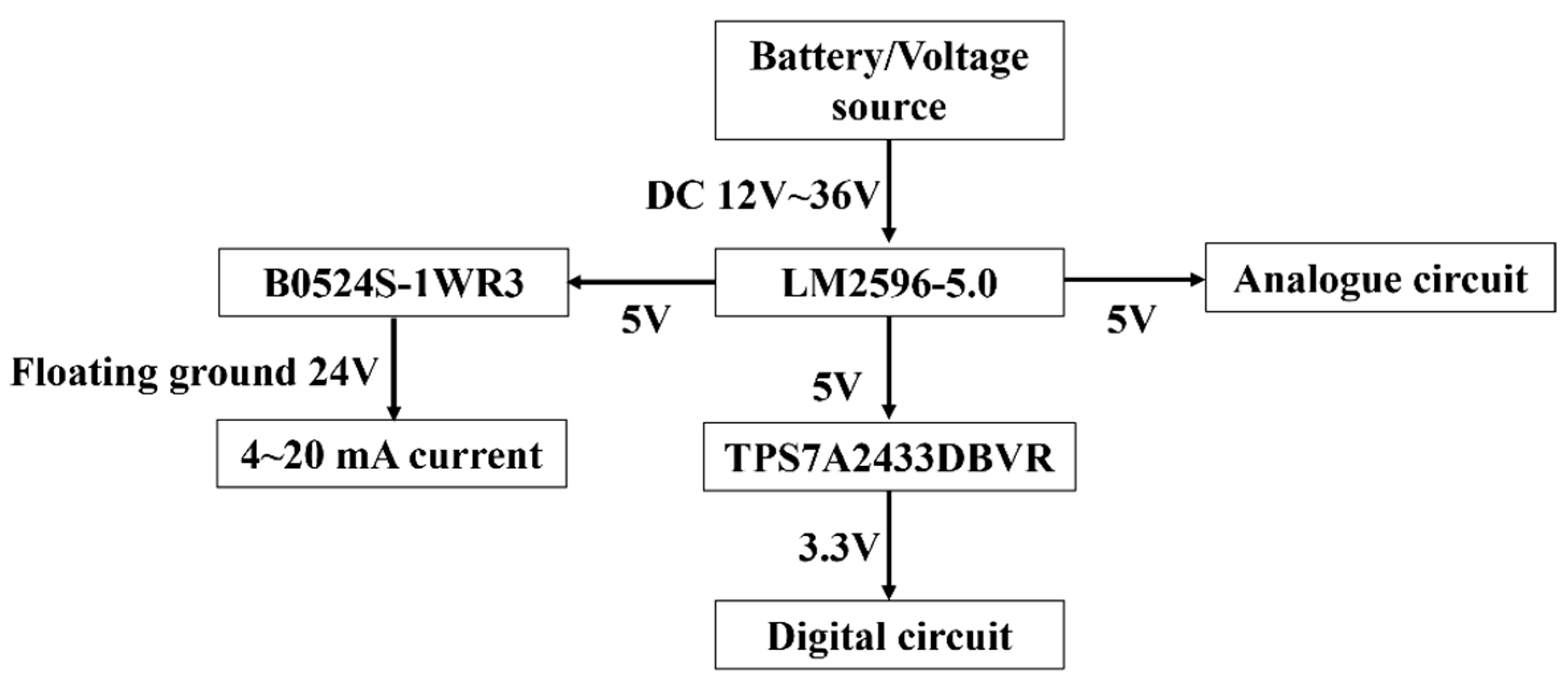
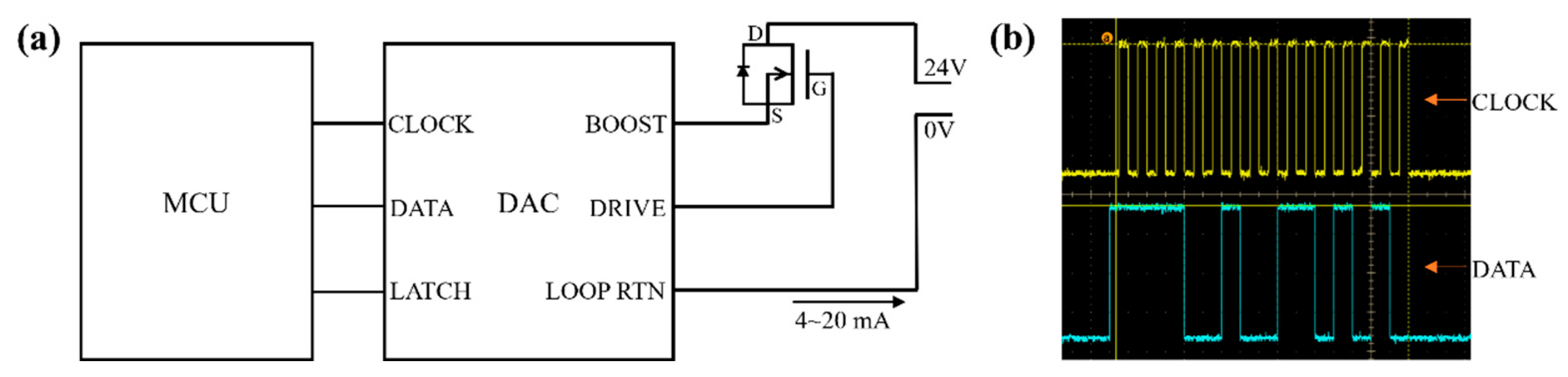
2.2. Circuit Design
2.3. Experimental Program
3. Results
4. Conclusions
Author Contributions
Funding
Institutional Review Board Statement
Informed Consent Statement
Data Availability Statement
Conflicts of Interest
References
- Chakraborty, S.; Bera, S.K.; Bera, S.C.; Mandal, N. Design of a Simple Temperature Transmitter Circuit of an Electric Heater Operated Water Bath. IEEE Sens. J. 2018, 18, 3140–3151. [Google Scholar] [CrossRef]
- Muralidhara, S.; Kothari, D. Design, development, and qualification tests of prototype two-channel cryogenic temperature transmitter. AIP Adv. 2022, 12, 11. [Google Scholar] [CrossRef]
- Srilakshmipathy, S.; Abhishek, R.; Deepa. Temperature and Humidity Monitoring in Silo. In Proceedings of the 2021 International Conference on Recent Trends on Electronics, Information, Communication & Technology (RTEICT), Bangalore, India, 27–28 August 2021; pp. 55–59. [Google Scholar]
- Liu, Z.J.; Tian, B.; Fan, X.; Liu, J.J.; Zhang, Z.K.; Luo, Y.Y.; Zhao, L.B.; Lin, Q.J.; Han, F.; Jiang, Z.D. A temperature sensor based on flexible substrate with ultra-high sensitivity for low temperature measurement. Sens. Actuator A-Phys. 2020, 315, 9. [Google Scholar] [CrossRef]
- Kuo, H.Y.; Takabayashi, N.; Lu, S.Y.; Mitani, T.; Liao, Y.C.; Liao, Y.T. Wirelessly Powered Temperature Sensing System Using Unmanned Aerial Vehicle for Environmental Monitoring. In Proceedings of the IEEE International Future Energy Electronics Conference (IFEEC), Taipei, Taiwan, 16–19 November 2021; IEEE: Piscataway, NJ, USA, 2021; pp. 16–19. [Google Scholar]
- Du, S.L.; Li, W.Y. Design and Application of Communication Module in Intelligent Temperature Transmitter Based on Freemodbus. In Proceedings of the 2018 4th Annual International Conference on Network and Information Systems for Computers (ICNISC), Wuhan, China, 19–21 April 2018; pp. 66–70. [Google Scholar]
- Mao, R.Z.; Kishimoto, M.; Iwai, H. Multipoint temperature measurement using serially connected resistor-capacitor parallel circuits by impedance spectroscopy. Sens. Actuator A-Phys. 2021, 331, 10. [Google Scholar] [CrossRef]
- Zhao, K.; Luo, N.; Liu, J.; Ding, W.; Li, L.; Jiang, W. Design and Implementation of PT100 Thermal Resistance Temperature Signal Isolation Transmitter Based on FPGA. In Proceedings of the 2021 5th International Conference on Automation, Control and Robots (ICACR), Nanning, China, 25–27 September 2021; pp. 135–139. [Google Scholar]
- Kim, J.; Kim, J.; Shin, Y.; Yoon, Y. A study on the fabrication of an RTD (resistance temperature detector) by using Pt thin film. Korean J. Chem. Eng. 2001, 18, 61–66. [Google Scholar] [CrossRef]
- Lee, C.Y.; Hsieh, W.J.; Wu, G.W. Embedded flexible micro-sensors in MEA for measuring temperature and humidity in a micro-fuel cell. J. Power Sources 2008, 181, 237–243. [Google Scholar] [CrossRef]
- Sim, J.K.; Hyun, J.; Doh, I.; Ahn, B.; Kim, Y.T. Thin-film resistance temperature detector array for the measurement of temperature distribution inside a phantom. Metrologia 2018, 55, 7. [Google Scholar] [CrossRef]
- Guan, W.B.; Zhai, H.J.; Jin, L.; Xu, C.; Wang, W.G. Temperature Measurement and Distribution Inside Planar SOFC Stacks. Fuel Cells 2012, 12, 24–31. [Google Scholar] [CrossRef]
- Feteira, A. Negative Temperature Coefficient Resistance (NTCR) Ceramic Thermistors: An Industrial Perspective. J. Am. Ceram. Soc. 2009, 92, 967–983. [Google Scholar] [CrossRef]
- Jia, J.; Zhu, H.X.; Liu, W.; Li, B.H.; Shi, Z.L.; Cui, Q.N.; Xu, C.X. Temperature Sensors Based on Negative Temperature Coefficient of ZnO Thin Films. IEEE Trans. Electron Devices 2023, 7, 5856–5862. [Google Scholar] [CrossRef]
- Chen, X.Y.; Li, X.H.; Gao, B.; Kong, W.W.; Zhao, P.J.; Chang, A.M. A novel NTC ceramic based on La2Zr2O7 for high-temperature thermistor. J. Eur. Ceram. Soc. 2022, 42, 2561–2564. [Google Scholar] [CrossRef]
- Masnicki, R.; Swisulski, D. Multi-Channel Virtual Instrument for Measuring Temperature—A Case Study. Electronics 2023, 12, 2188. [Google Scholar] [CrossRef]
- Guan, F.; Lin, X.J.; Dai, H.; Wang, J.R.; Cheng, X.; Huang, S.F. LaMn1−xTixO3-NiMn2O4 (0 ≤ x ≤ 0.7): A composite NTC ceramic with controllable electrical property and high stability. J. Eur. Ceram. Soc. 2019, 39, 2692–2696. [Google Scholar] [CrossRef]
- Chen, C.C. Evaluation of resistance-temperature calibration equations for NTC thermistors. Measurement 2009, 42, 1103–1111. [Google Scholar] [CrossRef]
- Alexander, M.D.; MacQuarrie, K.T.B. Toward a standard thermistor calibration method: Data correction spreadsheets. Ground Water Monit. Remediat. 2005, 25, 75–81. [Google Scholar] [CrossRef]
- Li, A.J.; Wang, H.T.; Dong, L.; Han, Q.; Wen, M.; Wen, X.D. Research on the Adaptability of Thermistor Calibration Equations. IEEE Instrum. Meas. Mag. 2023, 26, 13–18. [Google Scholar] [CrossRef]
- Mahaseth, D.N.; Kumar, L.; Islam, T. An efficient signal conditioning circuit to piecewise linearizing the response characteristic of highly nonlinear sensors. Sens. Actuator A-Phys. 2018, 280, 559–572. [Google Scholar] [CrossRef]
- Huo, P.; Wang, J.H.; Fan, L.C.; Liu, Z.J.; Wang, B.; Chang, A.M.; Yao, J.C. Effect of solid contents on the electrical properties of Co2.77Mn1.71Fe1.10Zn0.42O8 ceramic prepared by slurry spin coating technique. Sens. Actuator A-Phys. 2021, 332, 9. [Google Scholar] [CrossRef]
- Huo, P.; Wang, J.H.; Liu, Y.; Yan, Y.Q.; Liu, Z.; Shi, C.Y.; Chang, A.M.; Yao, J.C. Formation of a high stability NTC thick film by low-temperature sintering of Co2.77Mn1.71Fe1.10Zn0.42O8 ceramics containing Bi2O3-B2O3-SiO2-ZnO glass frits. Sens. Actuator A-Phys. 2022, 347, 113951. [Google Scholar] [CrossRef]
- Sarkar, S. Platinum RTD sensor based multi-channel high-precision temperature measurement system for temperature range −100 °C to +100 °C using single quartic function. Cogent Eng. 2018, 5, 15. [Google Scholar] [CrossRef]
- Li, X.; Sun, W.; Zhong, Z.; Shen, J.X. Design of a temperature transmitter with contactless power and data transmission. In Proceedings of the 2017 20th International Conference on Electrical Machines and Systems (ICEMS), Sydney, NSW, Australia, 11–14 August 2017; pp. 1–6. [Google Scholar]
- Jovanovic, J.; Denic, D. NTC thermistor nonlinearity compensation using wheatstone bridge and novel dual-stage single-flash piecewise-linear adc. Metrol. Meas. Syst. 2021, 28, 523–537. [Google Scholar] [CrossRef]
- Chang, L.; Zhang, G.G. The Design of Intelligent Temperature Transmitter Based on HART Protocol. In Proceedings of the 2nd International Conference on Instrumentation and Measurement, Computer, Communication and Control (IMCCC), Harbin, China, 8–10 December 2012; pp. 1499–1502. [Google Scholar]
- Witt, T.; Mena, R.; Cornell, E. Single Chip, 2-wire, 4-20mA Current Loop RTD Temperature Transmitter Design. In Proceedings of the 40th Annual Conference of the IEEE-Industrial-Electronics-Society (IECON), Dallas, TX, USA, 29 October–1 November 2014; IEEE: Piscataway, NJ, USA, 2014; pp. 2380–2383. [Google Scholar]
- Liu, G.; Guo, L.; Liu, C.L.; Wu, Q.W. Evaluation of different calibration equations for NTC thermistor applied to high-precision temperature measurement. Measurement 2018, 120, 21–27. [Google Scholar] [CrossRef]
- Liu, G.; Guo, L.; Liu, C.L.; Wu, Q.W. Uncertainty propagation in the calibration equations for NTC thermistors. Metrologia 2018, 55, 437–445. [Google Scholar] [CrossRef]
- White, D.R. Interpolation Errors in Thermistor Calibration Equations. Int. J. Thermophys. 2017, 38, 11. [Google Scholar] [CrossRef]


| Characteristic | Thermocouples | Platinum Resistors | NTC Thermistors |
|---|---|---|---|
| Materials Used | Different metal combinations | Platinum (wire or film) | Semiconductor materials |
| Change Parameters | Voltage | Resistance | Resistance |
| Temperature Range | −200 °C to 2300 °C (depending on type) | −200 °C to 850 °C | −200 °C to 1000 °C |
| Sensitivity | 1–80 mV/°C | 0.385%/°C (for Pt100) | −2%/°C~−6%/°C |
| Response Time | Fast 0.1–10 s | Slow 1–50 s | Fast 0.1–10 s |
| Stability | Moderate | Excellent | Moderate |
| Cost | Low | High | Low to Moderate |
| Advantages | Wide temperature range, rugged, low cost | High accuracy, linear response, stable | High sensitivity, small size, low cost |
| Disadvantages | Nonlinear response, drift over time, cold end compensation, low sensitivity | Slow response time, higher cost, sensitive to shock | Nonlinear response, limited temperature range |
| R (Ω) | R1 (Ω) | R2 (Ω) | ΔR2 (Ω) | Standard Deviation of Measured Values | Variation Coefficient (%) | ΔT (°C) |
|---|---|---|---|---|---|---|
| 500 | 500.347 | 500.036 | 0.037 | 0.0314 | 0.0063 | −0.0050 |
| 900 | 899.388 | 899.916 | −0.084 | 0.0945 | 0.0105 | 0.0052 |
| 1500 | 1498.34 | 1500.01 | 0.011 | 0.1228 | 0.0082 | −0.0003 |
| 2000 | 1997.5 | 2000.34 | 0.335 | 0.2212 | 0.0111 | −0.0075 |
| 5000 | 4988.7 | 5000.84 | 0.842 | 0.3870 | 0.0077 | −0.0061 |
| 8000 | 7975.87 | 8001.34 | 1.336 | 0.8518 | 0.0107 | −0.0055 |
| 12,000 | 11,950.9 | 12,000.3 | 0.331 | 1.2447 | 0.0104 | −0.0008 |
| 15,000 | 14,928.3 | 15,000.4 | 0.391 | 1.8363 | 0.0122 | −0.0007 |
| 18,000 | 17,902.1 | 18,000.8 | 0.781 | 2.0814 | 0.0116 | −0.0012 |
| 25,000 | 24,823.9 | 25,000 | −0.048 | 1.1747 | 0.0047 | 0.0001 |
| Checked Temperature (°C) | Output Value (mA) | Platinum Resistance Temperature Value (°C) | ||
|---|---|---|---|---|
| 0 | 1 | Upstroke | 7.974 | −0.265 |
| Downstroke | 7.975 | −0.264 | ||
| 2 | Upstroke | 7.974 | −0.265 | |
| Downstroke | 7.976 | −0.263 | ||
| 3 | Upstroke | 7.975 | −0.265 | |
| Downstroke | 7.976 | −0.267 | ||
| Average value | 7.975 | 7.975 | ||
| 50 | 1 | Upstroke | 12.997 | 49.979 |
| Downstroke | 12.998 | 49.978 | ||
| 2 | Upstroke | 12.997 | 49.980 | |
| Downstroke | 12.998 | 49.978 | ||
| 3 | Upstroke | 12.997 | 49.979 | |
| Downstroke | 12.999 | 49.981 | ||
| Average value | 12.997 | 12.997 | ||
Disclaimer/Publisher’s Note: The statements, opinions and data contained in all publications are solely those of the individual author(s) and contributor(s) and not of MDPI and/or the editor(s). MDPI and/or the editor(s) disclaim responsibility for any injury to people or property resulting from any ideas, methods, instructions or products referred to in the content. |
© 2024 by the authors. Licensee MDPI, Basel, Switzerland. This article is an open access article distributed under the terms and conditions of the Creative Commons Attribution (CC BY) license (https://creativecommons.org/licenses/by/4.0/).
Share and Cite
Liu, Z.; Huo, P.; Yan, Y.; Shi, C.; Kong, F.; Cao, S.; Chang, A.; Wang, J.; Yao, J. Design of a Negative Temperature Coefficient Temperature Measurement System Based on a Resistance Ratio Model. Sensors 2024, 24, 2780. https://doi.org/10.3390/s24092780
Liu Z, Huo P, Yan Y, Shi C, Kong F, Cao S, Chang A, Wang J, Yao J. Design of a Negative Temperature Coefficient Temperature Measurement System Based on a Resistance Ratio Model. Sensors. 2024; 24(9):2780. https://doi.org/10.3390/s24092780
Chicago/Turabian StyleLiu, Ziang, Peng Huo, Yuquan Yan, Chenyu Shi, Fanlin Kong, Shiyu Cao, Aimin Chang, Junhua Wang, and Jincheng Yao. 2024. "Design of a Negative Temperature Coefficient Temperature Measurement System Based on a Resistance Ratio Model" Sensors 24, no. 9: 2780. https://doi.org/10.3390/s24092780