Design of a Capacitive Flexible Weighing Sensor for Vehicle WIM System

1
State Key Lab. of Industrial Control Technology, Institute of Automation Instrumentation,
Zhejiang University, Hangzhou 310027, Zhejiang province, China
2
China JiLiang University, Hangzhou 310018, Zhejiang province, China
*
Author to whom correspondence should be addressed.
Sensors 2007, 7(8), 1530-1544; https://doi.org/10.3390/s7081530
Submission received: 28 June 2007
/
Accepted: 3 July 2007
/
Published: 17 August 2007
Abstract
:With the development of the Highway Transportation and Business Trade, vehicle weigh-in-motion (WIM) technology has become a key technology and trend of measuring traffic loads. In this paper, a novel capacitive flexible weighing sensor which is light weight, smaller volume and easy to carry was applied in the vehicle WIM system. The dynamic behavior of the sensor is modeled using the Maxwell-Kelvin model because the materials of the sensor are rubbers which belong to viscoelasticity. A signal processing method based on the model is presented to overcome effects of rubber mechanical properties on the dynamic weight signal. The results showed that the measurement error is less than ±10%. All the theoretic analysis and numerical results demonstrated that appliance of this system to weigh in motion is feasible and convenient for traffic inspection.
1. Introduction
Nowadays a large majority of freight transportation is made by road in most countries, and the volume of ground transportation is keep increasing as the result of the fast growing industry and commerce. Moreover, because of the strong competition between transport modes and companies, transportation management was improved, which has led to an increase in the numbers of fully loaded trucks and their gross weights. Recently, there have been a significant number of vehicles illegally overloaded and the damage vehicles cause on the road is in direct proportion to the axle weight by 4th power. The overloaded transportation would greatly increase the cost for the pavement maintenance and repair, shorten the service life of pavement, even affect the traffic safety and capability. So it is imperative to build a Weigh station to solve these problem [1-2].
Weight information of vehicles acquired by static weighing (i.e. does not move) was a conventional method which was used widely these days. Though the precision of this way to measure the gross weight of vehicle is very high, there are many disadvantages of the method: it is not only expensive but also not possible to measure the weight of each axle separately. The most important is that it is inconvenient to weigh with stopping vehicles in some practical application [3-4].
Weigh-in-motion (WIM) is the technology for measuring the weight of moving vehicles. Currently there are two measurement modes of weigh-in-motion, namely gross weight and axle weight measurement. For gross weight measurement mode, the use of a larger scale platform caused the increases in difficulty of implement and the cost of construction. In contrast to axle weight measurement, measured weight of each axle separately, then gross weight through the system.
Today there are four major types of sensors that are used for a number of applications comprising traffic data collection, and weigh station enforcement: piezoelectric sensors, bending plate, load cell and optic fiber [5-9].
A. Piezoelectric Sensors
Piezoelectric sensors are made from a material that generates an electric charge when it is mechanically deformed. This effect was discovered by the Curie brothers in the late eighteenth century and took its name from the Greek word piezo, which means, “I apply pressure”. Particularly when pressure is applied to a polarized crystal, the resulting mechanical deformation generates an electrical charge. When an array of these polarized crystals are placed between two metallic plates, an externally applied force is converted to a proportional charge. This charge results in a voltage which is dependent on the external force. This type of sensor can be installed directly into a slot in the road for permanent applications, or taped down for portable applications.
B. Bending Plate
Bending plate WIM systems utilize plates with strain gauges bonded to the underside. As a vehicle passes over the bending plate, the system records the strain measured by the strain gauge and calculates the dynamic load. The static load is estimated using the measured dynamic load and calibration parameters. When the pavement is asphalt it is necessary to construct a concrete foundation to support the bending plate scale, and when the pavement is made by concrete, a shallow excavation is needed to install the plate.
C. Load Cell
Load cell WIM systems utilize a single load cell with two scales to detect an axle and weigh both the right and left side of the axle simultaneously. As a vehicle passes over the load cell, the system records the weights measured by each scale and sums them to obtain the axle weight. The installation of a single load cell WIM system requires a concrete vault.
D. Optic Fiber
In addition to other uses, fiber optics can act as a WIM sensor technology. A fiber optic sensor is made of two metal strips welded around an optical fiber. The sensor principle uses induced photo-elastic properties in glass fiber under a vertical compressive force. This induces separation in two propagating modes: a faster vertical mode and a slower horizontal mode. The pressure transferred to the optical fiber creates a phase shift between both polarization modes, which is directly related to the load on the fiber. The technology is still fairly theoretical.
However, the applications of most of these sensors have been limited by problems, such as, large volumes, difficult installation, high cost and inconvenient implement. In this paper, a novel capacitance weighing sensor was proposed. Conductive rubbers are used as electrodes and insulating rubber sandwiches between two electrodes. Platform and weighing sensor integration has been realized successfully. This design significantly reduces volume and weight of the WIM sensor and the striking feature of this sensor is that it is easy to carry, which can be rolled up due to its flexibility. The structure and sensing mechanism of the flexible weighing sensor are presented in the paper first. Then the measuring circuit of the WIM system is introduced. Based on this, experiments were performed and results were analyzed.
2. Vehicle Weigh-in-motion System
2.1. Sensor Design
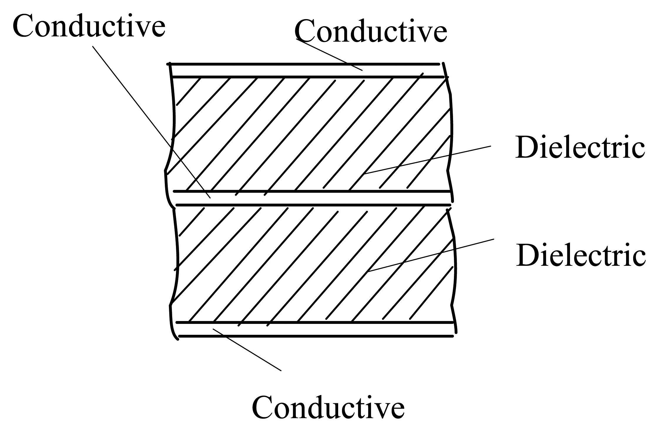
The sensor adopts a parallel plate capacitor structure, as shown in Fig.1, and is formed as a sandwich of three electrically conductive strata separated by two elastomeric dielectric layers to create a two-section electrical capacitor. Comparing with the normal capacitor which is formed by two electrodes, the structure it is not sensitive to electromagnetic interference.
The sensor weighs utilizing the variation in electrical capacity adapted to be loaded by a force to be measured. The conductive strata form the plates of a capacitor, and as a weight is applied to the sensor the elastomeric dielectric between the strata is compressed, the separation between the strata is reduced, and the capacitance of the weighing sensor increases.
The conductive strata comprise a conductive rubber material having 0.01Ω/cm volume resistance and dimension of 0.5m×0.5m that sold by Beijing TPY S&T Co., Ltd. The material has satisfactory conductivity. The dielectric layers comprise silica rubber bonded to the inner faces of the conductive strata.
The rubber materials of the same type can grow together after a period of time because of autohension [10]. When choosing dielectric layers material between the electrodes, rubbers with low molecular diffusivity and little mineral filler (such as carbon black) which might enhance autohension of rubber materials, should be adopted. Otherwise rubber molecule would diffuse to conductive strata, which may destroy the conductivity. The dielectric layers comprise silica rubber bonded to the inner faces of the conductive strata in the experiments.
The main advantages of the sensor are that: ➀light weight, easy to carry by rolling it up due to its flexibility. ➁less susceptible to unevenness of the pavement than conventional sensors, which has better contact with pavement because of its flexible characteristic. ➂less susceptible to high frequency vibration and impulse which can be absorbed because rubber materials have high internal resistance.
2.2. Design of WIM System's Measuring Circuit
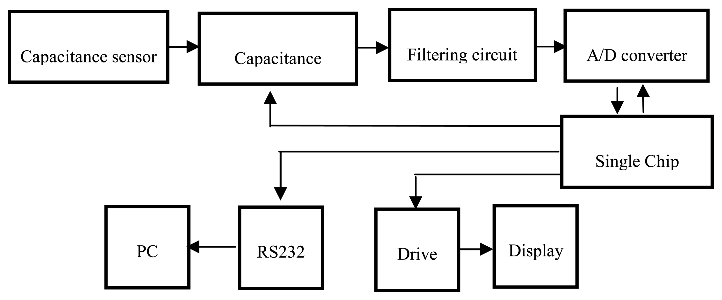
In this paper, the method of capacitance-to- voltage (C-v) has been taken to measure capacitance. Variation of capacitance which is difficult to measure is converted to variation of voltage by measuring circuit. Block diagram of measuring circuit is shown in Fig.2.
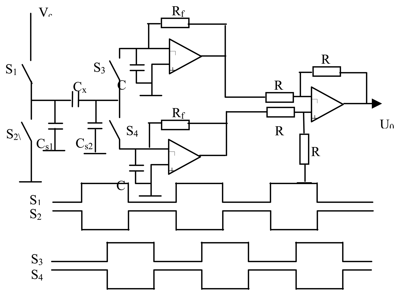
In many cases, the capacitance to be measure is small, say a few pF, but stray capacitance between the measurement terminals and earth can be large. Therefore, a stray-immune capacitance measuring circuit based on a four-phase is applied [11]. The most important features of this measuring circuit result in its stray-immunity and high stability. The detailed measuring circuit and those square waves are shown in Fig.3.
To measure the unknown capacitance Cx, two square-wave signals are applied to two complementary metal-oxide-semiconductor (CMOS) switches (CD4066), S1 and S2, so that the left side of Cx is connected either to Vc or earth. The other two square-wave signals are used to control the other two CMOS switches, S3 and S4.
LPC2134 (ARM7 series) sold by Zhouligong company is applied to produce 100kHz pulse series. There are four 50/50 duty square-wave signals with 0°, 90°, 180°, and 270° phases, which are used to control the operation of the measuring circuit. The output voltage from the circuit is
where f is excitation frequency, Vc is excitation voltage, and Rf is feedback resistance.
Variation of capacitance to be measured is much smaller than the natural capacitance of the sensor. Therefore, the natural capacitance should be offset in order to improve the system accuracy. Compensated capacitance Cc is used to offset the natural capacitance. In Fig.3 the left side of the unknown capacitance Cx is attached to compensated capacitance Cc through a phase inverter and the other side of Cx is attached to the other side of Cc. By the method, the natural capacitance is basically offset and the system accuracy is improved.
3. Model
3.1. Weighing System Model
The materials of capacitive sensor presented in this paper are rubber, so properties of the sensor are influenced largely by rubber mechanical properties. Rubber materials are viscoelasticity. As the name implies, these materials respond to external forces in a manner intermediate between the behavior of an elastic solid and a viscous liquid. Rubber viscoelasticity is mainly manifested in the relaxation phenomena [12]. Namely, the central importance of the time dependence of the mechanical properties of rubber lies in large magnitudes of theses dependencies when compared to other structural materials.
In order to gain greater insight into viscoelastic mechanical properties, viscoelastic model is set which can describe the complex deformation characteristic.
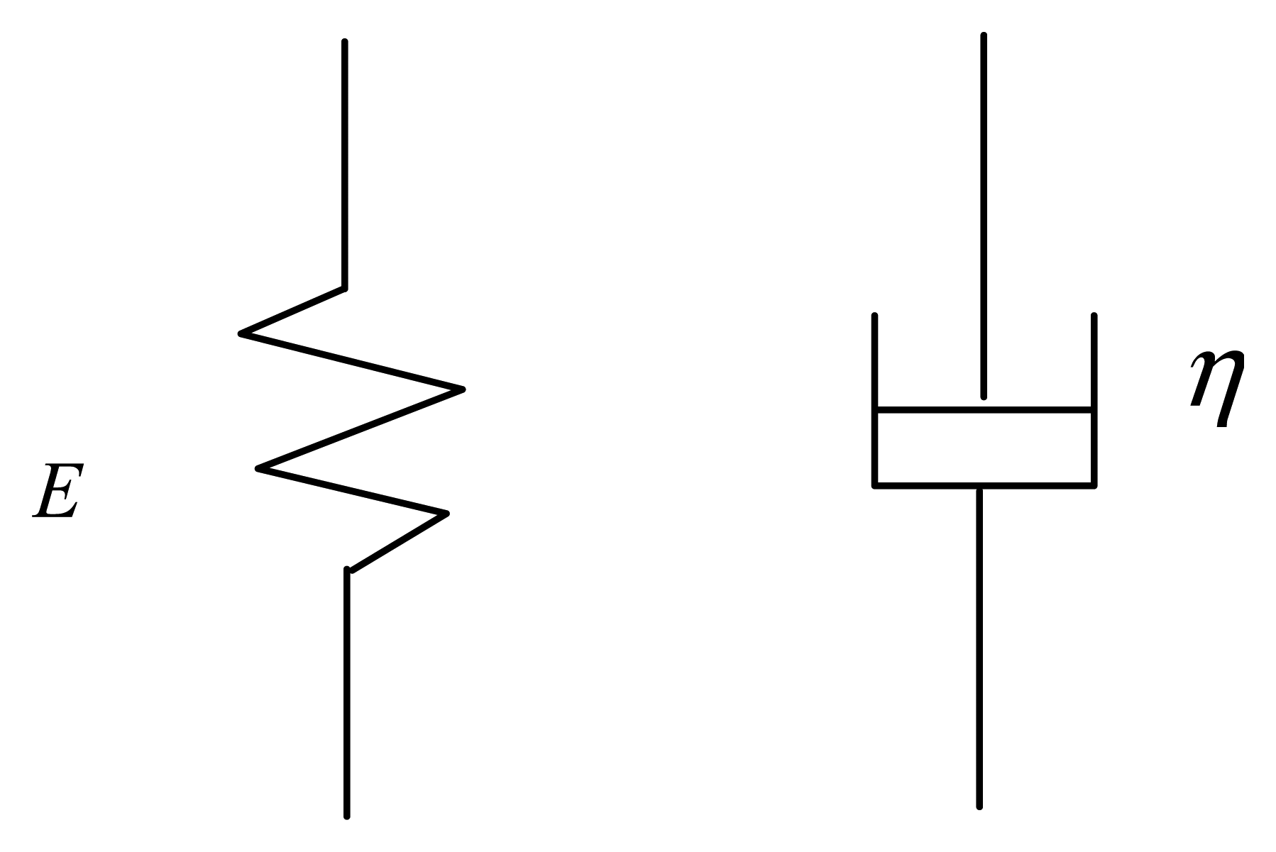
The simplest mechanical model of elastic body is a pure Hookean spring (Fig. 4(a)). This body is purely elastic and all inertial effects are neglected. Thus if the Hookean spring is subjected to an instantaneous stress σ, it will respond instantaneously with a strain ε, σ and ε being related by the equation
where E is elastic modulus.
On the other hand, the dominant characteristic of fluids is not their elasticity, but rather their viscosity. Newton's law
is the equation of motion for a model with a simple linear viscous behavior, where η is viscosity. The mechanical analogue of equation (3) is the dashpot element (Fig.4 (b)).
The mechanical response of viscoelastic bodies such as rubber materials are poorly represented by either the spring or the dashpot. So the viscoelatic models can be represented by a combination of the spring and dashpot elements. Normally, there are four major models: Maxwell model, Kelvin model and Maxwell-Kelvin model. Maxwell model is a series of a spring and a dashpot, which is usually used in considering stress relaxation processes and Kelvin model consists of the same fundamental elements as the Maxwell model, except here the spring and dashpot are in parallel. And Kelvin model is usually used in creep processes. The responses of both the Maxwell and Kelvin models to several kinds of deformation processes are much simpler than those of real rubber materials. Thus these simple models do not provide good approximations of the viscoelastic behavior of rubber. In order to overcome these deficiencies, Maxwell -Kelvin model is applied that consist of combinations of Maxwell and Kelvin elements in the paper.
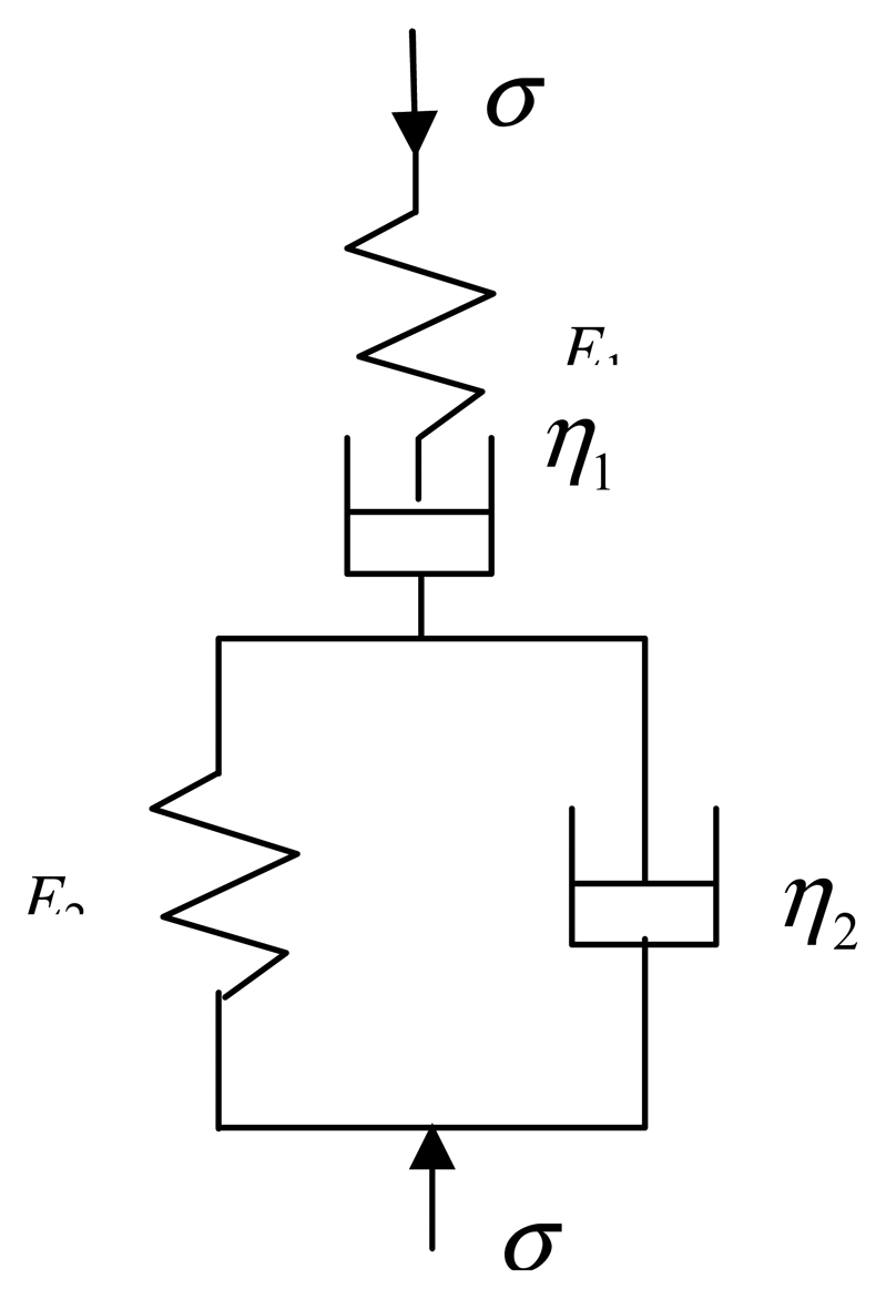
Maxwell-Kelvin model is a series of a Maxwell model and a Kelvin model, as shown in Fig. 5 which has two spring elements and two dashpot elements. Here the springs are ideally linear with their strain proportional to the stress applied. The dashpots represent a viscous response. The time rate of change of the strain of a dashpot is proportional to the stress applied.
In all of the individual elements (E1, η1 and E2), the stress is the same and the total strain ε is the summation of the individual strains by each element. One can then write:
Eliminating ε1, ε2 and ε3 using above equations, the relationship between stress and strains can be obtained.
And
so
Substituting (6), (7), (10) into the next equation, the physical equation of Maxwell-Kelvin model can be obtained
The model is subjected to an instantaneous constant stress σ. Thus Equation (11) becomes
since dσ/dt is zero.
Solving the differential equation (12) gives
Due to characteristic of the model and elements, when t is zero, one has
which, when substituted into (13) and simplified, results in
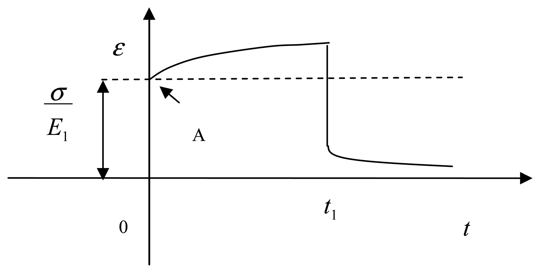
From the equation above, it is clear that ε0 is equal to σ/E1 when t is zero. Namely, there is only elastic strain. With time increasing, creep happens continuously and the time rate slows down, at last the curve tends to an asymptote, as shown in Fig.6.
In the paper, output signal from the sensor which is applied a constant force is shown in Fig. 7 (Note the initial jump, the exponential increase). Comparing Fig.6 with Fig.7, namely comparing the theory with the experimental strain curve, it can be seen that the agreement is good. Therefore Maxwell-Kelvin model is capable of describing mechanical response of the capacitive flexible weighing sensor presented in the paper.
The strain is a function of time when the sensor is applied a constant stress. In order to decrease the effect of time, the weigh-in-motion system presented in the paper only records the instantaneous strain produced by the instantaneous constant stress, namely elastic strain ε0 as the axle load such as the voltage of A point shown in Fig. 6 and 7. Applying the method, the accuracy of measurement can be improved by removing error to the system by time.
In the experiment, the output signal from the sensor is shown in Fig.9 as the vehicle passes over the platform. Because the platform is short, the action time is instantaneous (in several hundred milliseconds) when vehicle passes over the platform at certain speed. The elastic strain of capacitive flexible sensor just happens and then the stress vanishes. Therefore the system measures the peak voltage of curve produced by the two axle of vehicle as the elastic strain, calculates the axle weights and sums them to obtain the gross weight.
3.2. Rubber Resilience
Rubber is deformed when a constant force is applied to it. And after an applied force vanishes rubber decreases the deformation [13].
At the time of t1, a stress -σ which is equal in magnitude and opposite in direction is superposed to the original. The strain can be obtained from equation (16):
Two deformations are superposed:
From the equation (18), it can be seen that first the immediate drop from unloading is of the same magnitude as the initial jump from loading, namely the elastic strain ε0 as shown in Fig. 6. The resilience process is fast. Then the speed of resilience slows down obviously. The sensor response after an applied force vanishes is shown in Fig.8. Thus rubber does not return to the original length when a vehicle just passes over the platform.
According to Boltzmann superposition principle, two stresses are applied to the rubber at the two different times respectively and the two stresses act independently and the resultant strains add linearly. Therefore, in theory, the unreturnable part of the flexible sensor caused by last vehicle does not affect the measurement on the next vehicle due to the principle of physical independence of stresses.
The sensor is applied by a weight of 80kg at the three different initial values and measured respectively. The initial values and the sensor reading are shown in Table 1.
It could be seen from experiment that the variation of capacitance of the sensor does not change on the whole due to the different initial value. The phenomenon satisfies Boltzmann superposition principle. So the unreturnable part does not affect the measurement.
4. Experimental Results and Discussion
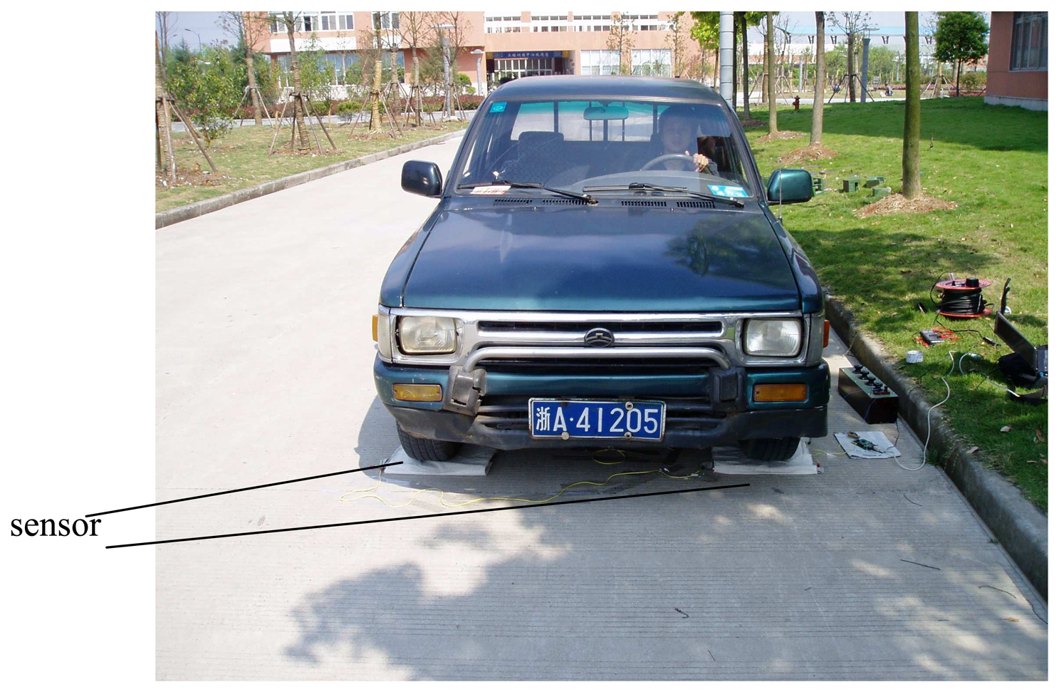
The experiments on dynamic vehicle weighing were performed by varying the load. A laboratory model of the weigh-in-motion system was used for the experiments. The Great wall pickup truck cc1021s whose weight is 1650kg was weighed in motion. The experimental setup is shown in Fig. 9. First, each axle of truck was weighed statically. Then the vehicle crossed the platform of the sensor, at different speeds: low speed, normal speed, high speed. The signals from the sensor is sampled and stored in the computer. Experimental data obtained with load sorting from 0kg to 420kg at the three different speeds are summarized in Table 2.
Fig. 10 (a) is the axle loads signal generating from the capacitive flexible weighing sensor when a two-axle vehicle passes over the platform. As a vehicle passes over the sensor, capacitance of the sensor increases, and the variation of capacitance is converted to variation of voltage which can be sampled and saved as digital file using analogy/digital (A/D) technique by measuring circuit. From Fig. 10 (a) it can be seen that original signal is affected by noise and is difficult to process. Therefore, it is important for signal de-noising to remain the accurate characteristics of original signal. Recently, the wavelet transform, a scale-frequency representation of a signal, has become very popular tool in signal processing. This transform constitutes a sort of remedy for limitation involved in the Short Time Fourier Transform resolution, and it is usually applied to detection, extraction, compression and de-noising of signals. The basic idea behind signal processing with wavelets is that, like in Fourier analysis, a signal can be decomposed into its component elements through the use of basis functions. In the case of Fourier, the basis functions are sine and cosine waves. In the case of wavelet analysis, the basis functions consist of the wavelet scale function and scaled and shifted versions of the mother wavelet function. In the paper, signal is brought to the level 8 through the wavelet decomposition. The reconstruction of signal is based on both the original approximation components and the details components modified by the hard thresholding operation. The mother wavelet function is coif3 that belongs to coiflet series. The result is shown in Fig.10 (b) which demonstrates the feasibility and applicability of the de-noising method. The system measures the peak voltage of de-noising curve produced by the two axle of vehicle as the elastic strain, calculates the axle weights and sums them to obtain the gross weight.
The experimental result turns out that comparing the value measured by WIM system to the statically measured value, the maximal error of vehicle's gross weight is ±7.72% and average error is ±1.715%, whose accuracy surpasses error of gross weight is ±10% when confidence is 95%. It has been shown that the capacitive flexible weighing sensor can be used in the vehicle Weigh-in-Motion system, and the obtained results are successful and satisfying. Fitting a Maxwell-Kelvin model to the strain response of the sensor demonstrates the model can expose the characteristics of the sensor.
5. Repeatability of the Sensor
A hydraulic universal material testing machine is used for the application of pressure. Three experimental results under the same loading conditions are compared in Fig.11 demonstrating that the capacitive flexible weighing sensor has good repeatability.
6. Conclusion
Weigh-in-motion is a method of weighing which can be applied in all situations where variable dynamic loads occur. Many existing weighing sensors have been limited due to large volumes, hard to install, high cost and inconvenience to carry. A novel capacitive flexible weighing sensor constructed by rubber materials is proposed in the paper. The electrodes of the capacitor are made by conductive rubber and the gap materials between the electrodes are insulting rubbers with low molecular diffusivity. The main advantage of the sensor is easy to carry, which can be rolled up due to its flexible characteristic. A major contribution of this paper was to expose the viscoelastic characteristics of the sensor response and to suggest methods for dealing with these characteristics. Theoretical analysis and experimental results are presented. The results verify that using the sensor to weigh in motion is feasible. In the paper, only the experiments under the slow speed conditions have been performed and the accuracy of WIM measured vehicle weights has not been affected obviously by speed. So in the future, the experiments under the high speed conditions could be performed and the effect of speed is to be studied. Other works such as temperature properties of the sensor, installation issues and effects of geometrical form of stressed part are to be studied. Furthermore, the measuring results should be transmitted and displayed by using wireless transmission technology with a view to designing really portable weighing equipment. The flexible sensor should be further improved on materials, measuring circuit and so on in order to achieve the higher precision.
Acknowledgments
This work was supported in part by Zhejiang Provincial Natural Science Foundation of China (No. M503193).
References and Notes
- Liu, W.; Hu, J.; Peng, L. Discussion on the Urgency of Establishing Weighting Stations in China Highway Network to Control Overloading Problem. Northeastern Highway 2003, 26, 12–14. [Google Scholar]
- Wang, J.; Wu, M. An Overview of Research on Weigh-in-motion System. Proc. of the 5th World Congress on Intelligent Control and Automation; IEEE, 2005; pp. 5241–5244. [Google Scholar]
- Cebon, D.; Jacob, B. Weigh-in-motion of axles and vehicles for Europe (WAVE). General Report. 2001. [Google Scholar]
- Cheng, L.; Zhang, H.; Cao, X. Vehicle Weigh-in-motion Technology. Chinese Journal of Scientific Instrument 2006, 27, 943–948. [Google Scholar]
- McCall, B. State's successful practices weigh-in-motion handbook. 1997. [Google Scholar]
- Teral, S.R. Fiber optic weigh-in-motion: looking back and ahead. Optical Engineering 1998, 3326, 129–137. [Google Scholar]
- Wang, K. A fiber-optic weigh-in-motion system based on fiber bragg grating technologies; A dissertation of Stevens Institute of Technology, 2005. [Google Scholar]
- Nikolaidis, D.R. Real-time speed, classification, and weigh-in-motion using a single, spatially distributed fiber-optic sensor; A dissertation of Florida Institute of Technology, 2002. [Google Scholar]
- Yannis, G.; Antoniou, C. Integration of Weigh-in-Motion Technologies in Road Infrastructure Management. ITE Journal 2005, 39–43. [Google Scholar]
- Zhang, D. Modern Rubber Compound Design, 1st Ed. ed; Chemical Industry Press: Beijing, 1994; pp. 126–130. [Google Scholar]
- Yang, S. Micro-capacitance sensor based on a four-phase detection technique. Journal of Transducer Technology 2003, 22, 13–15. [Google Scholar]
- Aklonis, J.J.; MacKnight, W.J. Introduction to Polymer Viscoelasticity, 2nd Ed. ed; A Wiley-Interscience Publication: New York, 1983; pp. 19–188. [Google Scholar]
- Zhang, Y.J. Test Method and Technique on Dynamic, Static Stiffness and Structure Elasticity-Back Properties for rubber and Plastic Products. Part A: Physical Testing 2003, 39, 298–311. [Google Scholar]
Figure 1.
Mechanical construction of the capacitive flexible weighing sensor.

Figure 2.
Block diagram of measuring circuit.

Figure 3.
Measuring circuit and switching wave forms, with stray capacitances shown (Cs1, Cs2).

Figure 4.
Spring and dashpot model.

Figure 5.
Maxwell-Kelvin model.

Figure 6.
Strain curve for Maxwell-Kelvin model.

Figure 7.
Response of the sensor after a force apply.

Figure 8.
Response of the sensor after an applied force vanishes.

Figure 9.
Experimental setup.

Figure10.
Response of the sensor to a passing vehicle: (a) the original signal; (b) the de-noised signal.
Figure10.
Response of the sensor to a passing vehicle: (a) the original signal; (b) the de-noised signal.

Figure 11.
Illustration of the repeatability of the sensor.


| Initial value (v) | Sensor reading (v) |
|---|---|
| 0.316 | 0.356 |
| 0.31 | 0.35 |
| 0.304 | 0.346 |
| Weight and statically measured value | Speed (m/s) | Measured value (v) | Error (%) |
|---|---|---|---|
| 1650kg 0.826v | 0.5 | 0.822 | -0.48 |
| 1.67 | 0.829 | 0.36 | |
| 2 | 0.826 | 0 | |
| 1710kg 0.856v | 0.44 | 0.853 | -0.35 |
| 1.42 | 0.824 | -3.74 | |
| 2.78 | 0.851 | -0.58 | |
| 1770kg 0.886v | 0.33 | 0.898 | 1.35 |
| 1.67 | 0.896 | 1.31 | |
| 2.22 | 0.898 | 1.35 | |
| 1830kg 0.916v | 0.56 | 0.918 | 0.22 |
| 1.42 | 0.914 | -0.22 | |
| 2 | 0.952 | 3.93 | |
| 1890kg 0.946v | 0.5 | 0.975 | 3.07 |
| 1.25 | 0.934 | -1.27 | |
| 3.61 | 1.019 | 7.72 | |
| 1950kg 0.976v | 0.28 | 0.983 | 0.72 |
| 1.17 | 0.953 | -2.36 | |
| 2 | 0.967 | -0.92 | |
| 2010kg 1.006v | 0.44 | 1.03 | 2.39 |
| 1.25 | 0.97 | -3.58 | |
| 2.22 | 1.01 | 0.4 | |
| 2070kg 1.036v | 0.67 | 1.01 | -2.51 |
| 1 | 1.02 | -1.54 | |
| 1.42 | 1.026 | -0.97 |
□Note: Error=(output(WIM)-output(statically measure))/(output(statically measure))×100%)
© 2007 by MDPI ( http://www.mdpi.org). Reproduction is permitted for noncommercial purposes.
Share and Cite
MDPI and ACS Style
Cheng, L.; Zhang, H.; Li, Q. Design of a Capacitive Flexible Weighing Sensor for Vehicle WIM System. Sensors 2007, 7, 1530-1544. https://doi.org/10.3390/s7081530
AMA Style
Cheng L, Zhang H, Li Q. Design of a Capacitive Flexible Weighing Sensor for Vehicle WIM System. Sensors. 2007; 7(8):1530-1544. https://doi.org/10.3390/s7081530
Chicago/Turabian StyleCheng, Lu, Hongjian Zhang, and Qing Li. 2007. "Design of a Capacitive Flexible Weighing Sensor for Vehicle WIM System" Sensors 7, no. 8: 1530-1544. https://doi.org/10.3390/s7081530