Article

A Micromachined Capacitive Pressure Sensor Using a Cavity-Less Structure with Bulk-Metal/Elastomer Layers and Its Wireless Telemetry Application

by
Kenichi Takahata
1,* and
Yogesh B. Gianchandani
2
1
Department of Electrical and Computer Engineering, University of British Columbia, 2332 Main Mall, Vancouver, BC V6T 1Z4, Canada
2
Department of Electrical Engineering and Computer Science, University of Michigan, 1301 Beal Ave, Ann Arbor, MI 48109-2122, USA
*
Author to whom correspondence should be addressed.
Sensors 2008, 8(4), 2317-2330; https://doi.org/10.3390/s8042317
Submission received: 31 December 2007 / Accepted: 31 March 2008 / Published: 2 April 2008
(This article belongs to the Special Issue Wireless Pressure Sensors)

Abstract

:
This paper reports a micromachined capacitive pressure sensor intended for applications that require mechanical robustness. The device is constructed with two micromachined metal plates and an intermediate polymer layer that is soft enough to deform in a target pressure range. The plates are formed of micromachined stainless steel fabricated by batch-compatible micro-electro-discharge machining. A polyurethane room-temperature-vulcanizing liquid rubber of 38-μm thickness is used as the deformable material. This structure eliminates both the vacuum cavity and the associated lead transfer challenges common to micromachined capacitive pressure sensors. For frequency-based interrogation of the capacitance, passive inductor-capacitor tanks are fabricated by combining the capacitive sensor with an inductive coil. The coil has 40 turns of a 127-μm-diameter copper wire. Wireless sensing is demonstrated in liquid by monitoring the variation in the resonant frequency of the tank via an external coil that is magnetically coupled with the tank. The sensitivity at room temperature is measured to be 23-33 ppm/KPa over a dynamic range of 340 KPa, which is shown to match a theoretical estimation. Temperature dependence of the tank is experimentally evaluated.

1. Introduction

Capacitive pressure sensors are favored for low-power and telemetric applications since they draw no DC power, and conveniently form passive inductor-capacitor (L-C) tank circuits for frequency-based measurement of pressure [1-3]. Micromachined capacitive pressure sensors have typically used an elastic diaphragm with fixed edges and a sealed cavity in between the diaphragm and the substrate below [4, 5]. Since this configuration relies on the deflection of a relatively thin diaphragm against a sealed cavity, in some applications there is a concern of robustness of the diaphragm and leaks in the cavity seal. Lead transfer for the sealed electrode has also been a persistent challenge. This has motivated the development of innovative fabrication methods that involve multilayer deposition, planarization, and other remedies, but require relatively high mask counts [6, 7]. Another approach to deal with this has been to move the sense gap outside the cavity [8].
This research explores a capacitive pressure sensor that consists of two micromachined metal plates with an intermediate polymer layer. Sandwich-type constructions with deformable intermediate layers have been used in some micromachined sensors [9, 10] as well as commercial pressure mapping systems (for, e.g., seat pressure monitoring) [11]. The selected configuration aims to eliminate the need of diaphragms and cavities from the micromachined capacitive sensors. Use of polymeric material that is soft enough to deform over a target pressure range allows thickness of the polymer, or capacitance of the parallel plate capacitor, to be dependent on hydraulic pressure that surrounds the device. This capacitive change can be interrogated by either a hard-wired interface or a wireless set-up in which the sensor serves as a capacitor of an L-C tank. The inductor coil can be separately coupled with the sensor (Figure 1a), or it can be formed by winding an insulated wire directly on the sensor to minimize the device size (Figure 1b). The wireless interrogation is performed by an external antenna/inductor that is magnetically coupled with the L-C tank device (Figure 2). Proper choice of materials compatible with particular environments will offer broader opportunities such as in automobile and biomedical applications that respectively include air pressure monitoring in the tires [12] and bowel pressure detection [13]. The inherent environmental compatibility is a significant advantage because it allows us to circumvent constraints and problems associated with the packaging [14] that in general degrades device performance and cost effectiveness in the device manufacturing [15].
This paper is constituted as follows. Section 2 describes the working principle and design of the sensor. The details of the fabrication process for the L-C tank device and the results are presented in Section 3. Section 4 reports the results of experimental characterization for the elastomer material used in this effort as well as the developed L-C tank device and the demonstration of wireless sensing with the device. These experimental results are evaluated in conjunction with the theoretical analysis in Section 5, followed by discussion in Section 6. Section 7 concludes the overall effort. Portions of this paper have appeared in conference abstract form in [16, 17].

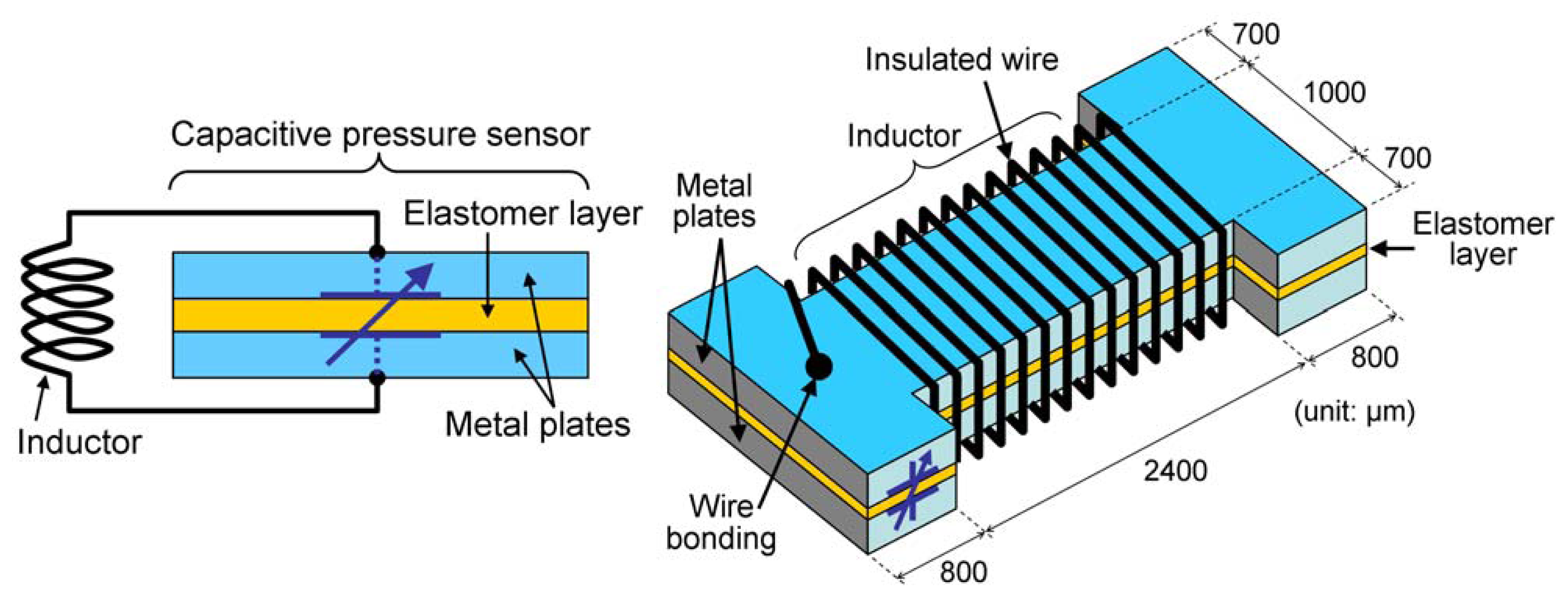
2. Device Principle and Design
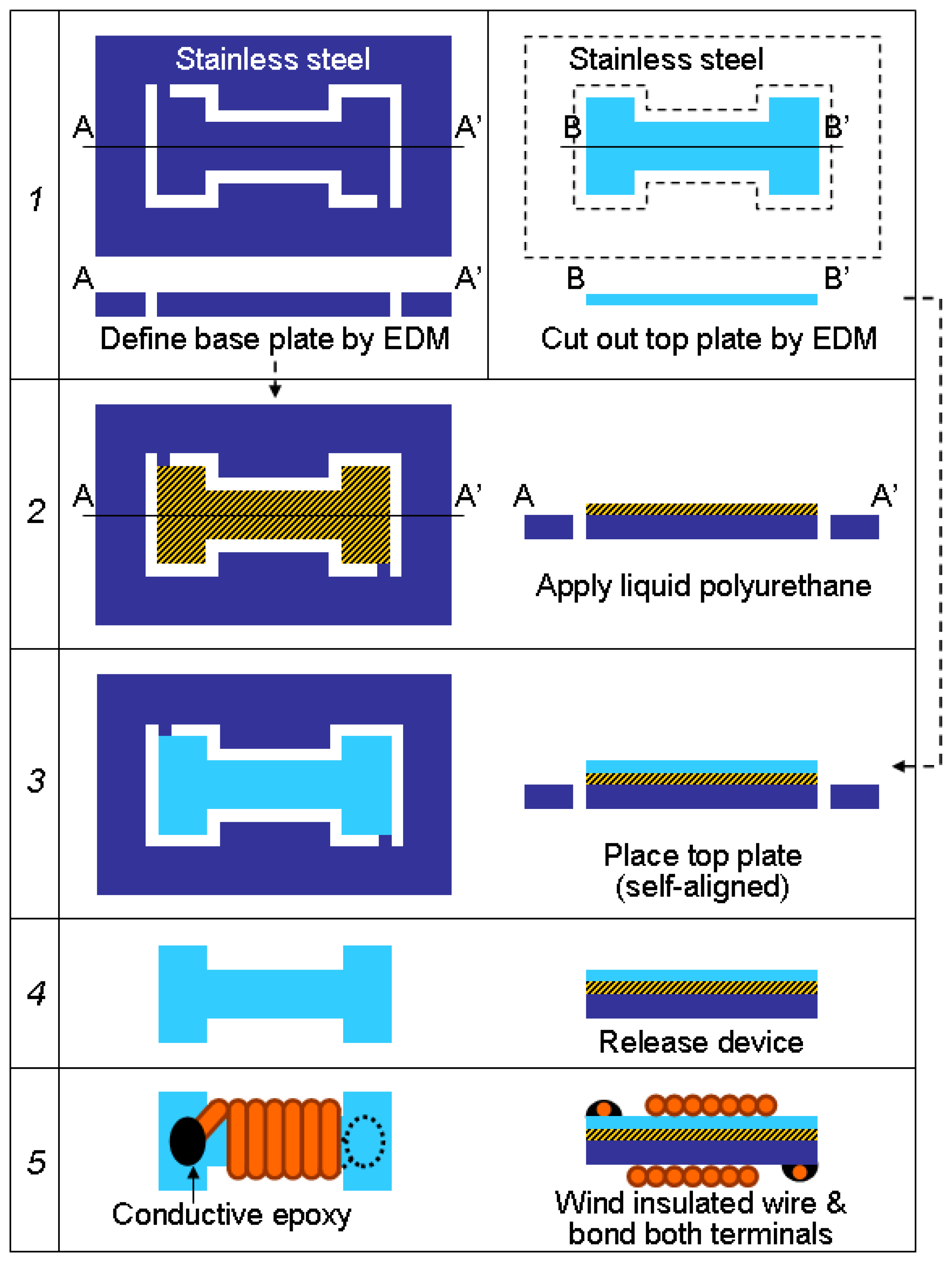
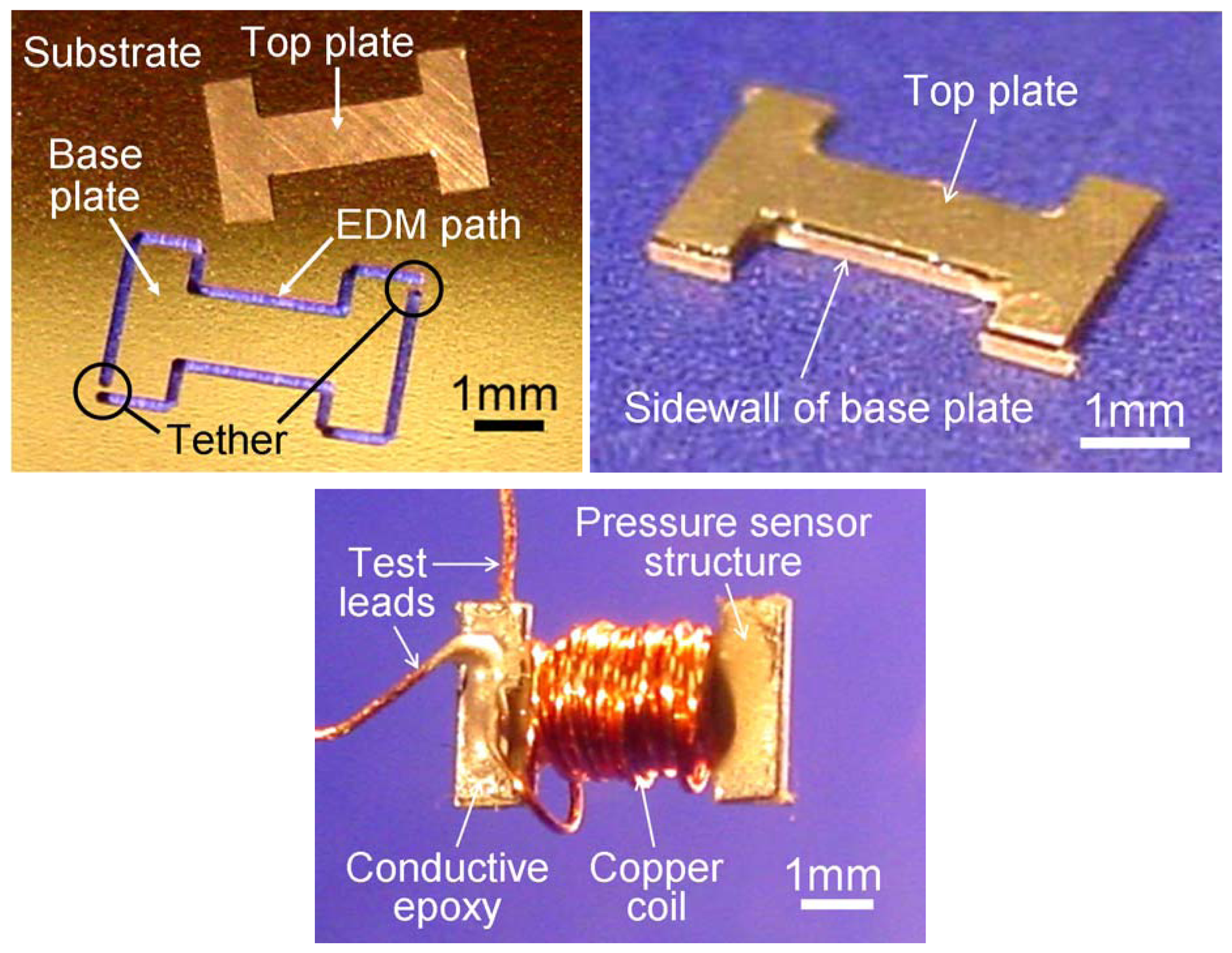
The capacitance of the device is determined by the thickness of the intermediate elastomer that is varied with the ambient pressure. An elastomer layer sandwiched between two rigid plates exhibits higher compression stiffness than the same layer without the plates in the direction perpendicular to the layer plane. For a rectangular layer of an incompressible, homogeneous elastomer that is bonded with rigid plates on both sides, the relationship between an applied pressure, P, on each of the plates and the resultant strain, e, can be expressed as [18]:
P = E A 2 ( S 2 S 0 2 ) E [ 1 + 1 3 ( Y 2 W 2 Y 2 + W 2 ) ] log ( 1 e )
where E is the Young's modulus of the elastomer, 2Y and 2W are the length and width of the rectangle layer, respectively, A is a constant given by
A = 4 3 + W Y ( 2 11 W 10 Y ) ,
and S is a geometric parameter called shape factor, which is approximately represented for the structure by
S = Y W 2 T ( Y + W ) = S 0 ( 1 e )
where 2T is the resultant thickness of the layer upon the compression and S0 is the original shape factor with the initial thickness (2T0) before the compression. The strain can be expressed as e=1-T/T0. The final thickness determines the capacitance of the structure, C = ε(4YW)/(2T), where ε is the permittivity of the elastomer, and then the resonant frequency of the L-C tank, f = 1 / ( 2 π L C ), where L is the inductance of the tank. The permittivity of polyurethane is reported to be stable over the pressure range that is involved in this effort [19]. With these, the ratio of the resonant frequency after the compression to the original one and that for capacitance can be coupled with the strain as
( f f 0 ) 2 = C 0 C = T T 0 = 1 e ,
where C0 and ƒ0 are the original capacitance and resonant frequency prior to the compression, respectively. Therefore, the relationship between the applied pressure and the ratio in the resonant frequency, ƒ/ƒ0 =F, can be expressed using Equations (1) and (4) as
P = E A S 0 2 2 ( 1 F 4 1 ) E [ 1 + 1 3 ( Y 2 W 2 Y 2 + W 2 ) 2 ] log ( F 2 ) .
For the configuration illustrated in Figure 1b, the two capacitive parallel plates with the indicated dimensions were microfabricated from stainless-steel sheets by micro-electro-discharge machining (μEDM) in this effort. μEDM is an electrothermal micromachining technique that can be used to cut any type of electrical conductors including all kinds of metals and alloys [20]. The machining typically uses cylindrical tungsten electrodes that are precisely shaped to have diameter ranging between 5 and 300 μm. Since these plates potentially have burrs at the edges as characteristic defects of the machining technique, the top plate was designed to be slightly smaller than the base plate (50-μm offset from all sides of the base plate) to minimize probability of physical/electrical contact between the two plates at the edges. Having the offset also assists with the self-alignment of the two plates in the assembly step described in the subsequent section.

3. Fabrication

In this effort, room-temperature-vulcanizing (RTV) liquid rubber of polyurethane was selected to form the elastomeric layer. This material offers mechanical robustness such as high tear and abrasive resistances, chemical resistance, and controllability of its softness over a wide range. It has been extensively used in medical implant applications [21] and was also used to fabricate micro/nanostructures for MEMS applications [22-24]. Other rubber materials such as polydimethylsiloxane (PDMS) that are formed with low-viscosity liquids are also potential candidates for the elastomer layer. Of course, mechanical properties such as plasticity limit, thermal expansion coefficient, would play a role in the final selection, as would considerations about manufacturing and integration.
The fabrication process is illustrated in Figure 3. As mentioned earlier, two capacitive plates were patterned with μEDM using a Panasonic™ MG-ED72W system (step 1). The base and top plates were cut from type-304 stainless-steel sheets with thickness of 200 μm and 50 μm, respectively, using cylindrical electrodes with 190-μm diameter (Figure 4a). The base plate was still connected to the original sheet through two tethers after the machining as shown in Figure 4a. A two-part polyurethane RTV liquid rubber (Poly 74-20, part A: polyurethane pre-polymer, part B: polyol, Polytek Development Co., PA, USA) with the softener (part C: plasticizer), which is vulcanized to very soft (<20 Shore A) and robust rubber, was used to form the intermediate polymer layer. The softness of the rubber can be adjusted by changing the proportion of the softener to be mixed. This effort used a formulation of part A:B:C=1:1:1. The mixed solution was applied to the upper surface of the base plate (step 2), and then the top plate was placed on it (step 3). In this step, the top plate is self-aligned to the base due to surface tension of the solution. After curing, the device was released as shown in Figure 4b by mechanically breaking the tethers (step 4). The measured thickness of the cured polyurethane layer was approximately 38 μm. The thickness of the layer can be adjusted by controlling the amount of the solution to be applied. (In large scale production, many of the kinds of parameters that are used to control the thickness of photoresist in photolithography – polymer viscosity, substrate spin speed, etc. – can be used in this context as well.) Finally, the device was coupled with an inductive coil: For the device in Figure 1b, the coil was formed by winding an enamel-coated copper wire (AWG 36, 40 turns) directly on the sensor and bonding the terminals on separate stainless-steel plates with conductive adhesive (step 5). The fabricated L-C tank shown in Figure 4c was measured to have nominal capacitance of 6.3 pF and inductance of 640 nH. Measured resonant frequency and quality factor of the tank, which were probed via test leads shown in Figure 4c, were 106 MHz and 1.9 respectively. The measured resonant frequency of the tank is close to the theoretical frequency of about 80 MHz that is obtained from the measured capacitance and inductance of the tank.
The capacitive structure was also coupled with and centered in a larger circular coil (5-mm diameter, 5 turns) formed using AWG 40 (ϕ) 80 μm; enamelled copper lead. This configuration was selected for preliminary wireless testing to enlarge the magnetic coupling coefficient [25] between the device and the external antenna/coil while reducing the negative impact of eddy current generated in the stainless-steel plates. The use of conducting adhesive between the stainless-steel plates (without surface preparation) and copper leads of the coil with a conductive adhesive provided high contact resistance between them. This caused the low quality factor mentioned earlier, which limits the frequency-based measurement including wireless implementations. The high resistance at the contact was believed to be due to the protective oxide layer of stainless steel. One simple method to circumvent this is to roughen the surfaces of the steel using various physical methods such as lapping and grit blasting to remove the oxide layer. The devices used for the wireless tests were constructed with top (50-μm thick) and base (100-μm thick) plates whose outer surfaces were mechanically roughened prior to bonding of the copper coils. The bonding was performed using a silver-filled conductive adhesive with low-resistivity (<2×10⁻⁴ Ω·cm), improving the electrical connection between them.

4. Experimental Results

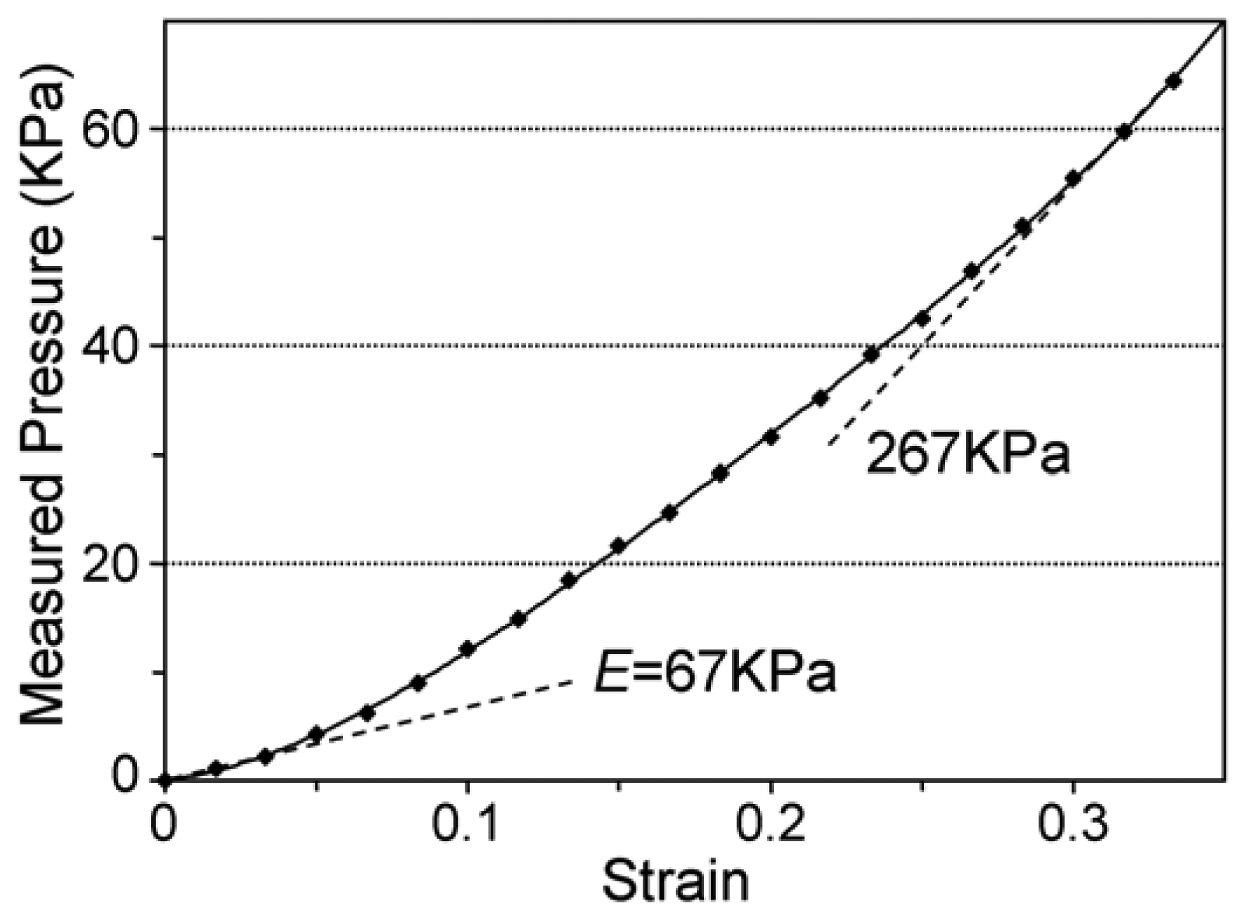
4.1. Measurement of Young's Modulus of Polyurethane Elastomer

To characterize the Young's modulus, E, of the polyurethane elastomer used for the fabrication, a compression test was performed using a 3-mm-cubic sample of the material without any plates attached to it. The measurement was performed with a digital force gauge (DPS-1, Imada Inc., IL, USA) that provided 1-mN resolution. Figure 5 plots measured pressure with varying strain up to 0.33 in the test, showing the initial compression modulus of 67 KPa, which is 15 % of the modulus reported in [22]. It also shows that the apparent modulus (corresponding to dP/de in Equation (1) for a sample bonded with the rigid plates) is effectively increased with strain, which is a common behavior of an elastomer associated with increase of the shape factor, S [18].

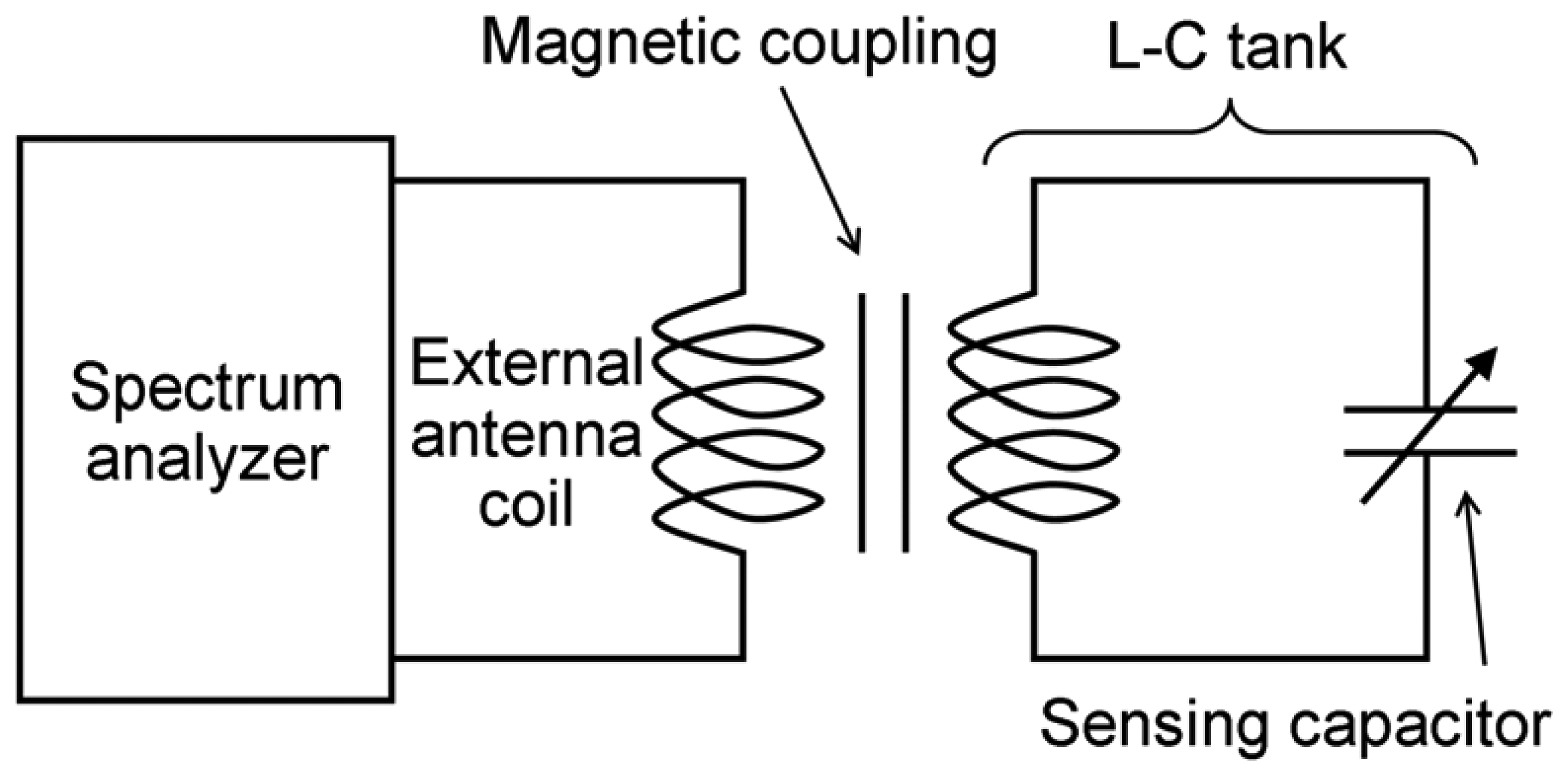
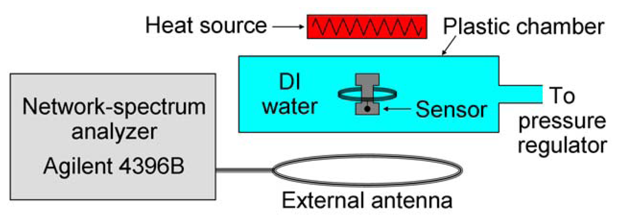
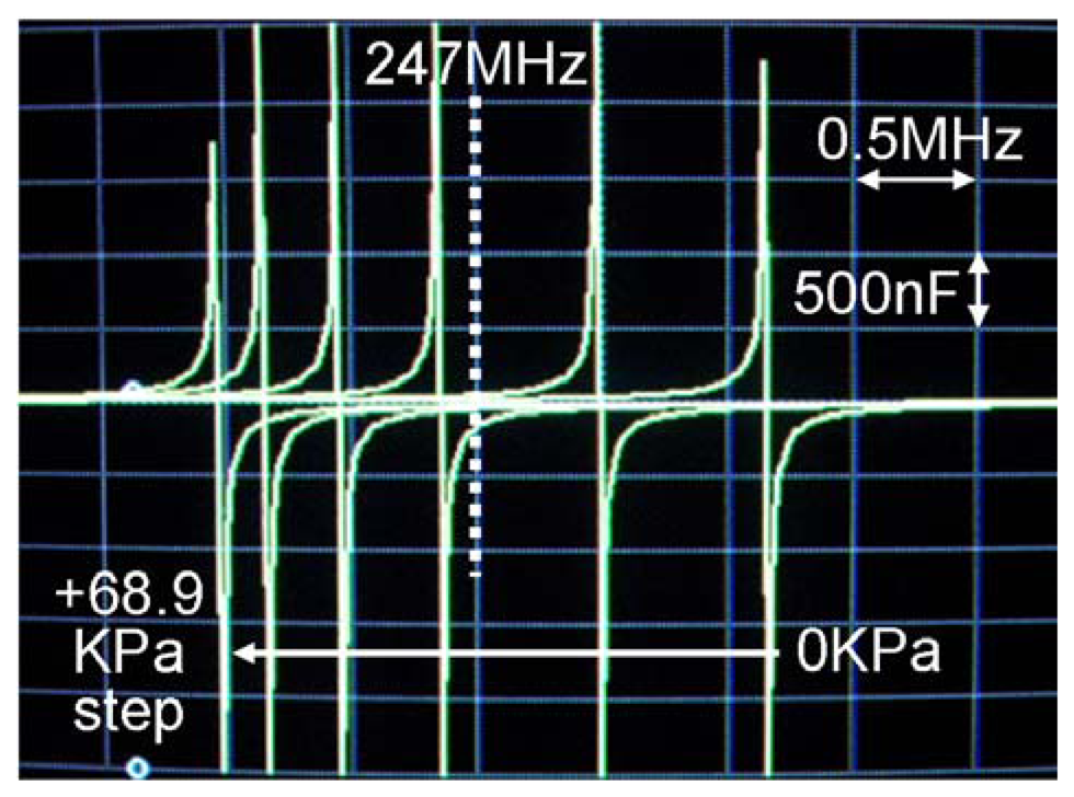
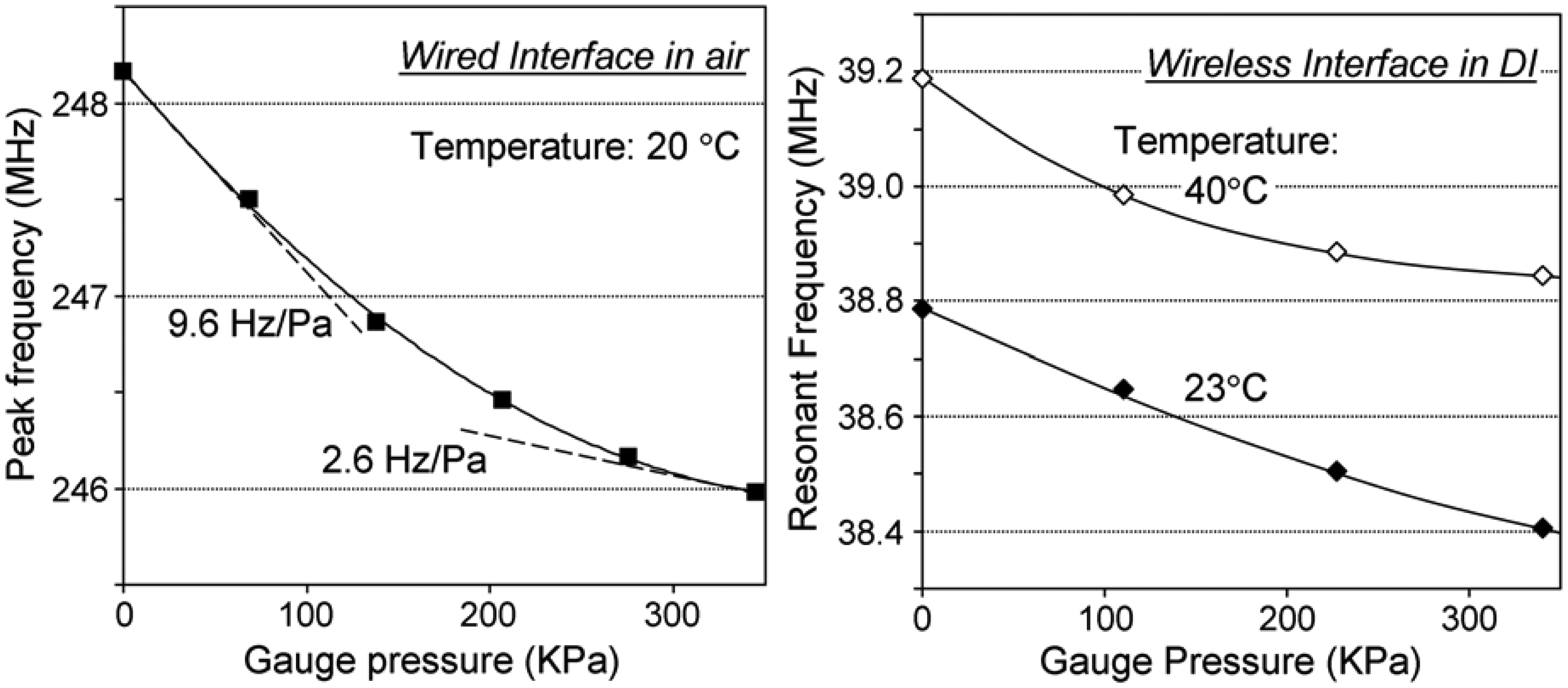
4.2. Characterization of the L-C tanks and Wireless Sensing Tests

The fabricated devices were tested with both hard-wired and wireless set-ups. In the wired set-up, the tank with the directly wound coil shown in Figure 4c was placed in a pressurized chamber with air, and the variation of its reactance peak with applied pressure was monitored by an HP4195 spectrum analyzer using the test leads transferred through the chamber wall. This reactance is an output that assumes a series capacitor-resistor model of the analyzer. This model exhibits the most distinct shift in the set-up.
Figure 6 illustrates the set-up used for the wireless sensing tests. The L-C tank device, which was coupled with the 5-mm-diameter coil, was placed within another sealed chamber with thin plastic walls, and magnetically coupled with an external coil (ϕ) ∼10 mm, 185 nH) through the chamber walls. The resonant frequency of the tank was monitored by tracking the frequency of the characteristic peak, which was reflected by the resonance of the tank, in an s-parameter (s11) of the external coil that was connected to a network-spectrum analyzer while changing pressure inside the chamber. The RF power fed from the analyzer to the external coil was 100 mW in this test. The chamber was filled with deionized (DI; water for this wireless experiment to demonstrate operation in liquid; the device provided a distinct resonant peak without packaging/coating for electrical protection. With the same set-up, the frequency dependence on temperature was also evaluated at atmosphere pressure. Temperature of the chamber was controlled by changing the distance between the device and a source of heat located outside of the chamber as shown in Figure 6.
Figure 7 shows the shifts of the reactance peaks measured with the wired set-up due to gauge pressure change in 69 KPa steps up to 345 KPa at room temperature (20 °C). The result is plotted in Figure 8a, indicating the response of 2.6-9.6 Hz/Pa and sensitivity of 11-39 ppm/KPa in this pressure range. The nonlinear behavior observed in the plot is consistent with the measured response in the compression modulus of the polyurethane rubber, i.e., the layer becomes stiffer as it is squeezed, resulting in the reduced response.
Figure 8b shows a typical measured response with the wireless set-up at room temperature. The reduced resonant frequency (of ∼39 MHz) was expected with the increased parasitic capacitance due to the operation in water. The frequency plot indicates a mildly saturating curve as similarly observed in the wired test in air (Figure 8a). The sensitivity is calculated to be 23-33 ppm/KPa for the pressure range up to 340 KPa. The same measurement at 40 °C also plotted in Figure 8b exhibits a similar saturating curve with an offset of about +0.4 MHz from that at room temperature. The slight difference in the responses with pressure shown in Fig. 8b may be due to the temperature dependence of mechanical properties of the particular polyurethane material used. The resonant frequency measured with varying temperature at atmosphere pressure is plotted in Figure 9, indicating a linear dependence with its coefficient of +783 ppm/°C. The increase of the resonant frequency suggests the decrease of the capacitance, which is expected to be due to the thermal expansion of the polyurethane. (The dielectric constant of polyurethane elastomer was reported to be stable at the temperature range used in this experiment [26].)

5. Theoretical Analysis of the Experimental Results

It is worth evaluating the measurement results obtained and their consistency with the theoretical estimation. To simplify the task for this initial analysis using Equation (5), the following calculation assumes that the capacitive structure has a simple rectangular shape with 4×1-mm2 area, which corresponds to the largest rectangular portion of the actual design (Figure 1b). It further assumes that the top and base plates as well as the intermediate elastomer layer have exactly the same dimensions of 4×1 mm2.
With the measured polyurethane thickness 2T0=38 μm and the lateral dimensions of the selected rectangle, i.e., 2Y=4 mm and 2W=1 mm, the constant A and the shape factor S0 are calculated to be 1.76 and 10.5, respectively. The measured Young's modulus, E, of the particular polyurethane is 67 KPa as observed in Figure 5. Using Equation (5) with these values, the normalized resonant frequency, F, as a function of hydrostatic pressure, P, is numerically solved and plotted in Figure 10. The “band” shown in the graph represents the possible range of the theoretical response with an assumption of ±5% variations in the thickness and Young's modulus of the polyurethane layer. The measurement result in Figure 8b at room temperature is also plotted in the graph for comparison. It is clearly seen that the theoretical estimation matches well with the measured response at lower pressure. It can also be seen that the measured response deviates from the theoretical response as the pressure is increased.

6. Discussion

The slightly lower response and deviation from the theoretical estimation seen in Figure 10 could be partially because of the presence of the extra portions (four 0.8×0.7-mm2 rectangles) in the actual device that were excluded in the analysis – these additional areas of the bonded elastomer layer can contribute to increased compression stiffness of the layer. Another hypothesis may be related to the deformation of the capacitive plates especially in the thinner top plate. The compressive strain of the elastomer layer depends on the lateral location on the structure under a uniform applied pressure [27]. Hence the upper plate can bend if it is not completely rigid, which is the real case. This deformation, i.e., non-uniform displacement of the plate may also be a partial source of the deviation. Non-ideal factors attributed to thin layer of the polyurethane material including inhomogeneity of the material and inclusion of particles while mixing the liquid components of the material can be a potential contributor as well. Nevertheless, it is noteworthy that the theoretical model for the sandwiched elastomer, which was originally developed for macro-scale blocks, is useful to find an approximate response, within a limited pressure range (up to 200-300 KPa), of a micromachined device with an elastomer layer whose thickness is only a few tens of microns.
The device construction will need some optimization for improved performance and practicality of the device. The temperature coefficient of this device (783 ppm/°C) is higher than typical values of the vacuum-cavity pressure sensors (<100 ppm/°C [28]), but is comparable to that of piezoresistive devices. (The sensitivities in frequency and capacitance are on the orders of 1-10 ppm/Torr and 10-100 ppm/Torr, respectively, which are lower than the typical 100-1000 ppm/Torr available from diaphragm-based sensors [28].) This may be addressed by tailoring the choice of the elastomer material: One of potential options would be the use of composite rubbers that incorporate inorganic negative thermal expansion (NTE) nanoparticles [29]. In addition, although the device was functional without packaging in DI water with high resistivity used for the wireless tests, it will need to be coated with a dielectric layer for electrical insulation when the device is surrounded by a conductive medium. This will be important especially for biomedical and implant applications where the device makes direct contact with polarizable liquids such as body fluid and blood. One of the simplest and most effective methods would be to coat the entire device with Parylene materials, which are dielectric, biocompatible polymers that have been used for a variety of products in electronic and biomedical fields [30] – the flexible, stretchable feature of the material is expected to minimize the impact of coating on the mechanical behavior of the device. The coating will also minimize the potential diffusion of liquid into the polymer from the sides not protected by the metal plates..
In this initial effort, the capacitive plates were micromachined using the traditional serial μEDM technique and were manually assembled (using a self-assembly technique). To increase the throughput of the production, these processes can potentially be performed in a batch manner by a combinational use of batch-mode μEDM [31] for cutting the plates and screen printing or spray coating for the liquid rubber layer formation. Use of planar spiral coils with bonding pads, possibly fabricated on flexible substrates, may be an effective approach to physical/electrical coupling with the capacitive sensor for the L-C tank assembly.

7. Conclusions

This research has explored a micromachined capacitive pressure sensor that eliminated both a diaphragm and a cavity from its construction. The sensor consists of two metal plates and an intermediate polymer, which is expected to offer high mechanical robustness and reliability. The device was constructed with micromachined stainless-steel plates fabricated by batch-compatible μEDM technique and polyurethane liquid rubber as the polymer layer that permitted self-aligning of the micromachined plates in the assembly process. This material combination can offer good corrosion resistance and robustness, potentially reducing the difficulties associated with packaging for selected applications. The sensor and 40-turn copper coils were combined to form L-C tanks, which were successfully used to implement frequency readout for pressure monitoring with the maximum sensitivity of ∼40 ppm/KPa and extended to the wireless telemetry measurement. The sensing was demonstrated in both air and liquid environments with up to 340 KPa gauge pressure. Future work will encompass structural and material optimization, as well as reliability testing.

Acknowledgments

The authors would like to thank TRIUMF, Vancouver, B.C., Canada, for providing access to their measurement equipment and Mr. Mark Richardson at the University of Michigan, Ann Arbor, for his assistance in the micromachining work. Y. Gianchandani acknowledges partial support from the IR/D program of the National Science Foundation (NSF), USA. The findings do not necessarily reflect the views of the NSF.

References and Notes

  1. DeHennis, A.D.; Wise, K.D. A wireless microsystem for the remote sensing of pressure, temperature, and relative humidity. IEEE/ASME J. Microelectromech. Syst. 2005, 14(1), 12–22. [Google Scholar]
  2. Shina, K.H.; Moona, C.R.; Leeb, T.H.; Limb, C.H.; Kimb, Y.J. Flexible wireless pressure sensor module. Sensor. Actuator. 2005, A 123-124, 30–35. [Google Scholar]
  3. Fonseca, M.A.; English, J.M.; von Arx, M.; Allen, M.G. Wireless micromachined ceramic pressure sensor for high-temperature applications. IEEE/ASME J. Microelectromech. Syst. 2002, 11(4), 337–343. [Google Scholar]
  4. Chau, H.; Wise, K.D. An ultraminiature solid-state pressure sensor for a cardiovascular catheter. IEEE Trans. Electron Dev. 1988, 35(12), 2355–2362. [Google Scholar]
  5. Ko, W.H.; Wang, Q. Touch mode capacitive pressure sensors for industrial applications. IEEE Int. Conf. Micro Elec. Mech. Syst. (MEMS) 1997, 284–289. [Google Scholar]
  6. Chavan, A.V.; Wise, K.D. A batch-processed vacuum-sealed capacitive pressure sensor. IEEE Int. Conf. Solid-State Sensor. Actuator. 1997, 1449–1451. [Google Scholar]
  7. Gogoi, B.; Mastrangelo, C.H. A low voltage force-balanced pressure sensor with hermetically sealed servomechanism. IEEE Int. Conf. Micro Elec. Mech. Syst. (MEMS) 1999, 493–498. [Google Scholar]
  8. Park, J.S.; Gianchandani, Y.B. A servo-controlled capacitive pressure sensor using a capped-cylinder structure microfabricated by a three-mask process. IEEE/ASME J. Microelectromech. Syst. 2003, 12(2), 209–220. [Google Scholar]
  9. Herber, S.; Eijkel, J.; Olthuis, W.; Bergveld, P.; van den Berg, A. Study of chemically induced pressure generation of hydrogels under isochoric conditions using a microfabricated device. J. Chem. Phys. 2004, 121(6), 2746–2751. [Google Scholar]
  10. Lei, M.; Choi, W.; Siegel, R.A.; Ziaie, B. An ultrasensitive microsensor based on self-aligned dry-patterned environmentally sensitive hydrogels. IEEE Int. Conf. Solid-State Sensor. Actuator. Microsyst. (Transducers) 2005, 1824–1827. [Google Scholar]
  11. Ashruf, C.M.A. Thin flexible pressure sensors. Sensor Review 2002, 22(4), 322–327. [Google Scholar]
  12. Kolle, C.; Scherr, W.; Hammerschmidt, D.; Pichler, G.; Motz, M.; Schaffer, B.; Forster, B.; Ausserlechner, U. Ultra low-power monolithically integrated, capacitive pressure sensor for tire pressure monitoring. IEEE Int. Conf. Sensors 2004, 1, 244–247. [Google Scholar]
  13. Magjarevic, R.; Ferek-Petric, B.; Lopandic, K. Biofeedback in rehabilitation of anal sphincter muscles. IEEE Int. Conf. Eng. Med. Biol. Soc. (EMBS) 2000, 423–426. [Google Scholar]
  14. Zhang, Y.; Tan, X.; Chen, W.; Zhang, G.; Liu, X. Study of MEMS packaging technology. IEEE Int. Conf. Electron. Packag. Technol. 2005, 643–646. [Google Scholar]
  15. Cohn, M.N.; Roehnelt, R.; Xu, J.; Shteinberg, A.; Cheung, S. MEMS packaging on a budget (fiscal and thermal). IEEE Int. Conf. Electron. Circ. Syst. 2002, 1, 287–290. [Google Scholar]
  16. Takahata, K.; Gianchandani, Y.B. A micromachined polyurethane/stainless-steel capacitive pressure sensor without cavity and diaphragm. IEEE Int. Conf. Solid-State Sensor. Actuator. Microsyst. (Transducers) 2005, 483–486. [Google Scholar]
  17. Takahata, K.; Gianchandani, Y.B. Bulk-metal-based MEMS fabricated by micro-electro-discharge machining. IEEE Can. Conf. Elect. Comput. Eng. (CCECE) 2007, 1–4. [Google Scholar]
  18. Hill, J.M.; Lee, A.I. Large elastic compression of finite rectangular blocks of rubber. Q. J. Mech. Appl. Math. 1989, 42(2), 267–287. [Google Scholar]
  19. Cheng, Z.Y.; Gross, S.; Su, J.; Zhang, Q.M. Pressure-temperature study of dielectric relaxation of a polyurethane elastomer. J. Polymer Sci. B Polymer Phys. 1999, 37(10), 983–990. [Google Scholar]
  20. Masaki, T.; Kawata, K.; Masuzawa, T. Micro electro-discharge machining and its applications. IEEE Micro Elec. Mech. Syst. (MEMS) 1990, 21–26. [Google Scholar]
  21. Lamba, N.; Woodhouse, K.; Cooper, S.L. Polyurethanes in Biomedical Applications; CRC Press: Florida, 1998. [Google Scholar]
  22. Engel, J.M.; Chen, J.; Bullen, D.; Liu, C. Polyurethane rubber as a MEMS material: Characterization and demonstration of an all-polymer two-axis artificial hair cell flow sensor. IEEE Int. Conf. Micro Elec. Mech. Syst. (MEMS) 2005, 279–282. [Google Scholar]
  23. Arias, F.; Oliver, S.R.J.; Xu, B.; Holmlin, R.E.; Whitesides, G.M. Fabrication of metallic heat exchangers using sacrificial polymer mandrils. IEEE/ASME J. Microelectromech. Syst. 2001, 10(1), 107–112. [Google Scholar]
  24. Campolo, D.; Jones, S.; Fearing, R.S. Fabrication of gecko foot-hair like nano structures and adhesion to random rough surfaces. IEEE Nano 2003, 2, 856–859. [Google Scholar]
  25. Finkenzeller, K. RFID Handbook: Fundamentals and Applications in Contactless Smart Cards and Identification, 2nd ed.; John Wiley & Sons: New York, 2003; pp. 70–71. [Google Scholar]
  26. Su, J.; Zhang, Q.M.; Kim, C.H.; Ting, R.Y.; Capps, R. Effects of transitional phenomena on the electric field induced strain-electrostrictive response of a segmented polyurethane elastomer. J. Appl. Poly. Sci. 1997, 65(7), 1363–1370. [Google Scholar]
  27. Holownia, B.P. Compression of bonded rubber blocks. J. Strain Anal. 1971, 6(2), 121–123. [Google Scholar]
  28. Gianchandani, Y.B.; Wilson, C.G.; Park, J. Micromachined pressure sensors: Devices, interface circuits, and performance limits. In The MEMS Handbook Second Edition: MEMS Applications; Gad-el-Hak, M., Ed.; CRC Press: Florida, 2006; Chapter 3. [Google Scholar]
  29. Agostini, G.; Corvasce, F.G. Tire with low thermal expansion component. United States Patent Application 2007. No. 20070074801. [Google Scholar]
  30. Fontaine, A.B.; Koelling, K.; Passos, S.D.; Cearlock, J.; Hoffman, R.; Spigos, D.G. Polymeric surface modifications of tantalum stents. J. Endovasc. Surg. 1996, 3(3), 276–283. [Google Scholar]
  31. Takahata, K.; Gianchandani, Y.B. Batch mode micro-electro-discharge machining. IEEE/ASME J. Microelectromech. Syst. 2002, 11(2), 102–110. [Google Scholar]
Figure 1. Bulk-metal/elastomer capacitive pressure sensor in the form of the L-C tank for frequency-based pressure monitoring: (a: left) Cross sectional view of the sensor coupled with a separate inductor, and (b: right) a device with an inductor wound on the sensor.
Sensors 08 02317f1
Figure 2. Electrical representation of the wireless measurement set-up with the L-C tank device.
Sensors 08 02317f2
Figure 3. Fabrication process flow to fabricate the capacitive pressure sensor (steps 1-4) and the L-C tank (step 5).
Sensors 08 02317f3
Figure 4. (a: upper left) Base and top plates for the capacitive sensor fabricated by μEDM (step 1 in Figure 3), (b: upper right) device released from the original sheet of the base plate (step 4 in Figure 3), and (c: lower) fabricated L-C tank with a coil wound using AWG-36 (ϕ) 127 μm; enamelled copper wire (step 5 in Figure 3). The tank is connected with the test leads for electrical characterization.
Sensors 08 02317f4
Figure 5. Pressure vs. strain measured with a 3-mm-cubic polyurethane rubber sample.
Sensors 08 02317f5
Figure 6. Set-up used for the wireless testing of the device with the 5-mm-diameter coil in liquid. The heat source is used to evaluate the sensor response at elevated temperature.
Sensors 08 02317f6
Figure 7. Frequency response of the reactance peak of the L-C tank measured with the wired set-up due to gauge pressure change from zero to 345 KPa in air at room temperature.
Sensors 08 02317f7
Figure 8. (a: left) Frequency response vs. gauge pressure plotted from the result in Figure 7 measured with the wired set-up in air at room temperature, and (b: right) similar measurement results with the wireless set-up in DI water at room and elevated temperatures.
Sensors 08 02317f8
Figure 9. Resonant frequency of the tank vs. temperature measured with the wireless set-up.
Sensors 08 02317f9
Figure 10. Comparison of relative frequency changes between the measured result from Figure 8b and the theoretical estimation based on the model in Equation (5).
Sensors 08 02317f10

