An Electromagnetically Excited Silicon Nitride Beam Resonant Accelerometer

Abstract
:1. Introduction
2. Design and Simulation
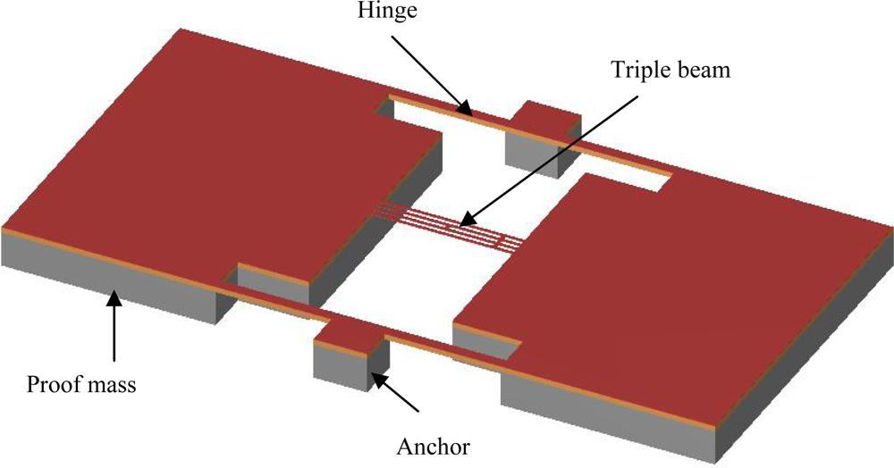
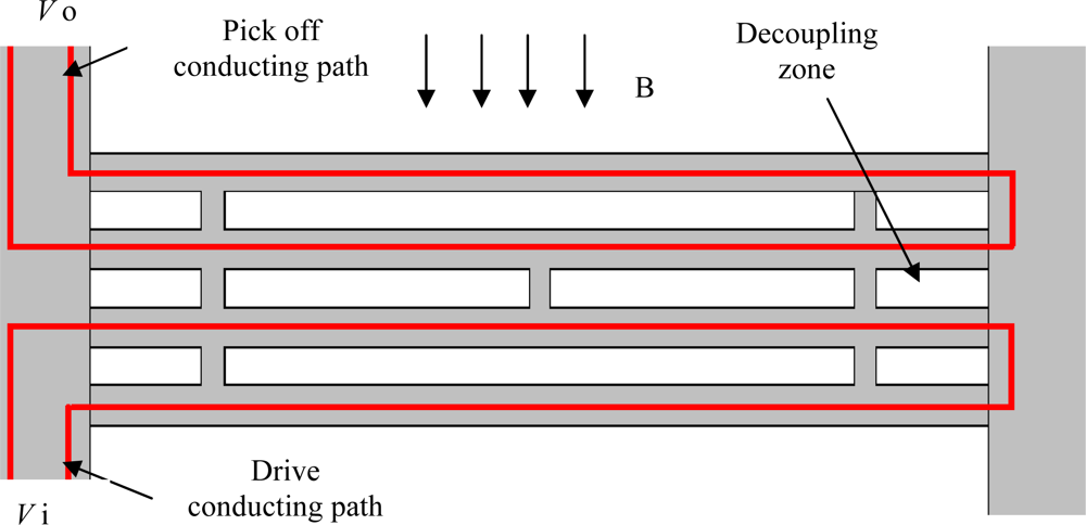
2.1 Chip design
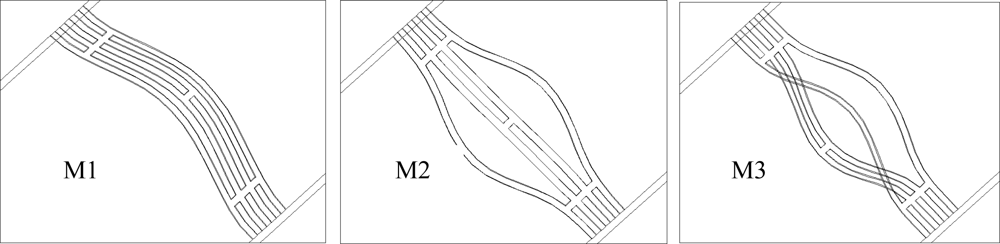
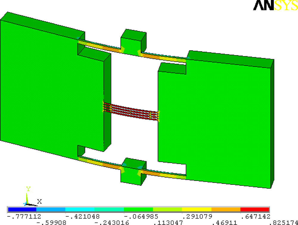
2.2 FEA Modeling
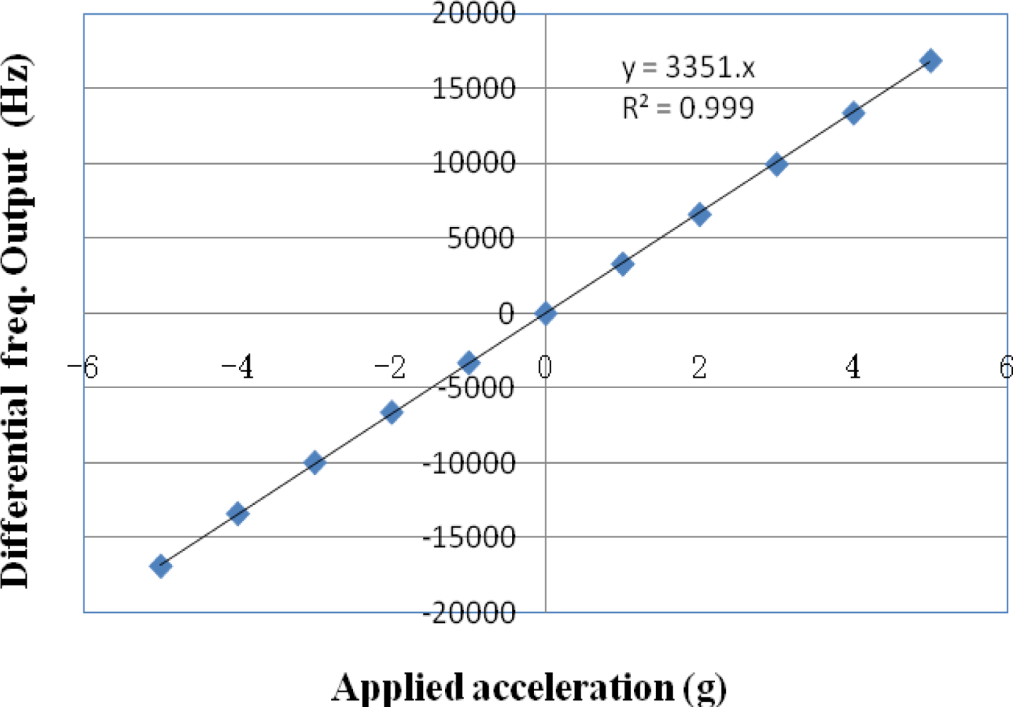
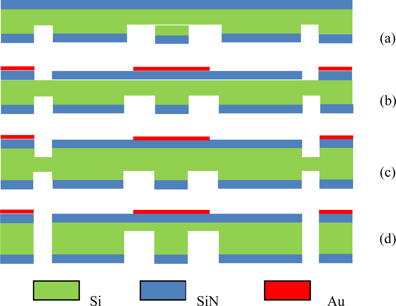
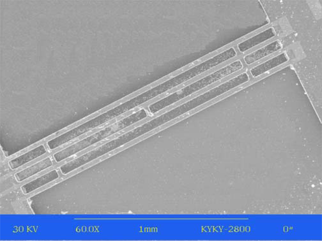
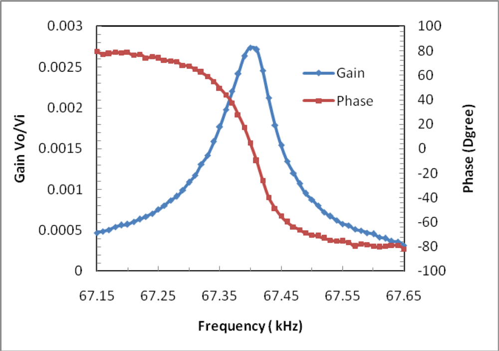
3. Experiments and Results
4. Conclusions
Acknowledgments
References and Notes
- Roessig, T.A.; Howe, R.T.; Pisano, A.P.; Smith, J.H. Surface micromachined resonant accelerometer. Proceedings of 9th International Conference on Solid State Sensors and Actuators, Transducers’97, Chicago, IL, USA; 1997; pp. 859–862. [Google Scholar]
- Seshia, A.A.; Palaniapan, M.; Roessig, T.A.; Howe, R.T.; Gooch, R.W.; Schimert, T.R.; Montague, S. A vacuum packaged surface micromachined resonant accelerometer. J. Microelectromechan. Syst 2002, 11, 784–793. [Google Scholar]
- Burrer, C.; Esteve, J. A novel resonant silicon accelerometer in bulk-micromachining technology. Sens. Actuat. A 1995, 46–47, 185–189. [Google Scholar]
- Roszhart, T.V.; Jerman, H.; Drake, J.; de Cotiis, C. An Inertial Grade, Micromachined Vibrating Beam Accelerometer. Proceedings of 8th International Conference on Solid-State Sensors and Actuators, Transducer ’95, Stockholm, Sweden, 1995; pp. 659–662.
- Ferrari, V.; Ghisla, A.; Marioli, D.; Taroni, A. Silicon resonant accelerometer with electronic compensation of input-output cross-talk. Sens. Actuat. A 2005, 123–124, 258–266. [Google Scholar]
- Jia, Y.; Hao, Y.; Zhang, R. Bulk silicon resonant accelerometer. Chin. J. Semiconduct 2005, 26, 281–286. [Google Scholar]
- Helsel, M.; Gassner, G.; Robinson, M.; Woodruff, J. A Navigation Grade Micro-Machined Silicon Accelerometer. IEEE Position Location and Navigation Symposium 1994, 51–58. [Google Scholar]
- Lee, B.L.; Oh, C.H.; Oh, Y.S.; Chun, K. A Novel Resonant Accelerometer: Electrostatic Stiffness Type. Proceedings of 10th International Conference on Solid-State Sensors and Actuators, Transducer ’99, Sendai, Japan, 1999; pp. 1546–1549.
- Chen, D.; Cui, D.; Xia, S. Design and Modeling of a Silicon Nitride Beam Resonant Pressure Sensor for Temperature Compensation. Proceedings of the 2005 IEEE International Conference on Information Acquisition, Hong Kong and Macau, China, 2005; pp. 240–242.
- Chen, D.; Cui, D.; Yu, Z.; Wang, L.; Cui, Z.; Xia, S. Thermally excited SiN beam resonant pressure sensor. Proceedings of SPIE 2001, 4408, 548–554. [Google Scholar]


| Loads | 0g | 1g (Z) | 100g (X) | 100g (Y) |
|---|---|---|---|---|
| M1 | 40773 | 42385 | 40774 | 40775 |
| M2 | 65798 | 67250 | 65800 | 65799 |
| M3 | 73722 | 75336 | 73722 | 73722 |
© 2009 by the authors; licensee MDPI, Basel, Switzerland This article is an open-access article distributed under the terms and conditions of the Creative Commons Attribution license (http://creativecommons.org/licenses/by/3.0/).
Share and Cite
Chen, D.; Wu, Z.; Liu, L.; Shi, X.; Wang, J. An Electromagnetically Excited Silicon Nitride Beam Resonant Accelerometer. Sensors 2009, 9, 1330-1338. https://doi.org/10.3390/s90301330
Chen D, Wu Z, Liu L, Shi X, Wang J. An Electromagnetically Excited Silicon Nitride Beam Resonant Accelerometer. Sensors. 2009; 9(3):1330-1338. https://doi.org/10.3390/s90301330
Chicago/Turabian StyleChen, Deyong, Zhengwei Wu, Lei Liu, Xiaojing Shi, and Junbo Wang. 2009. "An Electromagnetically Excited Silicon Nitride Beam Resonant Accelerometer" Sensors 9, no. 3: 1330-1338. https://doi.org/10.3390/s90301330