
Fire Hazards of Some Modern Solid Fuels


Centre for Environmental Safety and Risk Engineering, Victoria University, Werribee, VIC 3030, Australia
Energies 2017, 10(1), 113; https://doi.org/10.3390/en10010113
Submission received: 1 November 2016
/
Revised: 10 January 2017
/
Accepted: 12 January 2017
/
Published: 17 January 2017
Abstract
:Fire hazard during ship transportation of certain modern solid fuels is identified. A particular mechanism which may lead to catastrophic ship fire is discussed. A mathematical model predicting time to such fully developed fire (flashover time) I s proposed. An analytical solution is obtained for the developed model. An important part of this solution is a closed form analytical description of the smoke filling dynamics in a closed compartment. It is demonstrated that flashover time depends on a number of parameters. The relative importance of these parameters is discussed. Particular significance is attributed to fuel soot propensity (fuel soot yield) which is an intrinsic fuel property. This parameter controls the intensity of radiative heat exchange in the compartment, and its influence on flashover time is of paramount importance. It is suggested that fuels are ranked with respect to this parameter in order to describe their relative fire hazards. This ranking should be implemented into the regulatory framework governing fuel transportation by ships.
1. Introduction
There is a strong emphasis currently on production and use of fuels, alternative to traditional, for clean energy generation. Examples of such solid fuels are biomass fuels, including Refuse Derived Fuels (RDF) [1,2]. One of key questions that inevitably arises upon introduction of the new fuel is its safety, and in particular its behavior in the fire safety context. Although no rigorous fire safety regulations exist for the new fuels identified above, and the body of research on this topic is quite limited, existing studies point to potential fire hazards associated with such fuels.
In particular, the studies of Koseki [1] and Murasawa and Koseki [2] demonstrate that biomass fuels may develop spontaneous ignition if stored in large quantities. Particular mechanisms have been identified by Murasawa and Koseki [2]. They have described several stages leading to ignition of biomass fuels: (1) heat generation by fermentation; (2) heat generation by fatty acid ester; (3) water vaporization; and (4) further thermal decomposition of organic elements and ignition. These mechanisms have been considered in [1,2] in the context of fires developing in large biomass fuel piles in the open space, or within storage facilities containing such fuels.
It should be noted however that such fuels are also being transported in large quantities by ships [3,4,5]. This process presents new fire hazards associated with biomass fuels, to date not accounted for. The major difference between this scenario and those considered in [1,2] is that fuel is contained in a tightly sealed space (i.e., cargo compartment of a ship) and therefore smoke generated by the fire accidental fire (smoldering or flaming, no matter how small) will be maintained within the compartment. Under such conditions, hot smoke, upon sufficient accumulation, may serve as a source of thermal radiation directed towards unburnt fuel. Radiation from the smoke layer creates a positive feedback loop (i.e., temperature and mass of the smoke as well as intensity of radiation it emits grow as fire progresses) which may lead to essentially simultaneous ignition of all the virgin fuel in the compartment (fire flashover) and fire transition into the fully developed stage with catastrophic consequences.
This flashover mechanism essentially represents a specific thermal explosion scenario. Thermal explosion is a powerful fundamental concept in combustion science, extremely useful in various applications [6,7,8,9,10,11]. In particular, this concept has been adopted for description of flashover stages of compartment fires in the study [10]. However, such flashover mechanism has never been investigated in application to biomass fuel transportation, and has never been considered in application to fully closed compartments.
The fire hazard considered in the present paper is associated with a particular scenario of fire development in the cargo compartment of ships. The envisaged scenario is as follows.
Biomass fuels are normally transported in very large packs fitted into the ship’s cargo compartment. Images of the packs can be found in [3,5].
Under certain conditions, as explained in the studies [1,2] initial weak heat generation may occur which will lead later to initial fire through the stages (1)–(4) described above. This fire may be of very limited size, and may in fact involve smoldering combustion.
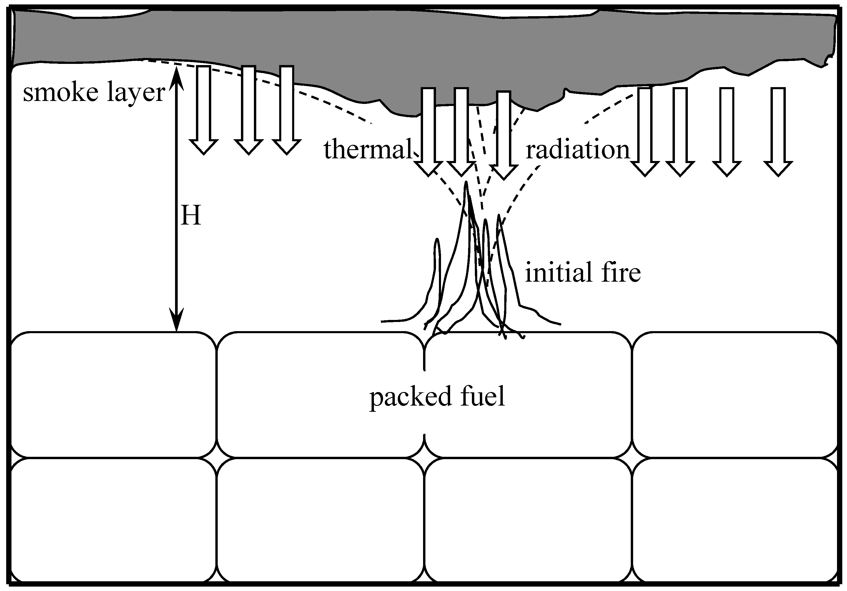
In open spaces, or in well ventilated storage facilities, evolution of such fire would normally be through a gradual increase in the heat release rate (HRR). This has been the case for fire accidents referred to in [1,2]. In the cargo compartment of ships, fire evolution would be different due to the possibility of very rapid involvement of total fire load (flashover). This scenario is presented in Figure 1.
Here, initial fire emerging as a result of autoignition via the stages (1)–(4) serves as a source of smoke accumulating in the compartment. At later stages, smoke temperature and concentration grow, giving rise to strong thermal feedback from the smoke layer to fuel. This radiative flux will be nearly evenly distributed along the fuel surface due to the nature of the smoke filling process (Figure 1). Once the level of radiation reaches a certain magnitude, initially unburnt fuel will be ignited, and this will happen essentially simultaneously throughout the compartment.
Rapid development of fires in the closed cargo compartment of ships generally results in catastrophic consequences. Numerous illustrations can be found in [4].
The approach taken in the present paper is to investigate the considered scenario using mathematical modeling. A relevant mathematical model is developed in the following section.
2. Mathematical Model
Initial fire, resulting from the autoignition (thermal explosion) of a portion of the fuel is assumed to have a constant HRR. This fire may develop in either the flaming or smoldering mode of combustion. The scenario that converts this initial fire into the catastrophic flashover scenario is considered.
We assume the compartment to be fully closed. In practice, some leaks may exist that initially allow oxygen for combustion to diffuse inside the compartment over a long time. However, in the smoke filling problem considered below, the effect of these leaks is negligible due to a limited duration of the filling process. Generally, some clearance height may exist between the roof of the cargo compartment and the surface of the packed fuel. The area of the exposed top surface of the fuel is denoted . Heat losses from the compartment are not considered in the present study.
In order to analyze the problem, some preliminaries from fire dynamics are needed to obtain a solution for the smoke filling problem in a compartment shown in Figure 1. The problem is considered via a zone approach, similar in nature to many smoke filling studies [12,13]. Consistent formulation of the smoke filling problem for the fully closed compartment is missing in the literature.
More precisely, the following fire plume correlations [12] are used. (From here up to the end of the paper, the convention is that waved variables are dimensional, and unwaved variables are non-dimensional.)
The mass flow rate and excess temperature in the fire plume are given as follow:
The correlation (1) gives an estimation of the mass flow rate through the cross section, at the height , in the fire plume. The correlation (2) provides an estimation of the excess (that is elevation above ambient) temperature at the centreline of the plume, at the height .
Here, is the fire HRR, , , are ambient air parameters (density, specific heat and temperature, respectively), is gravity accelearion, is numerical parameter.
The following scales are adopted to write up a convenient non-dimensional formulation for the smoke filling problem: for spatial scale, for time, (—unversal gas constant, —moelcular weight) for pressure, for density, for temperature, for the HRR, for mass flow rate. Additioanlly, and .
As usual in the zone approach to smoke filling problems [12,13], the two stratified layers are distinguished, namely containing the clean air (bottom) and the smoke (top). Spatially averaged properties attributed to the layers are distinguished by the subscripts “1”and “2”, respectively.
Using correlations (1) and (2) as well as the just introduced scaling, the set of non-dimensional Equations (3)–(8) below can be derived to describe the smoke filling problem in the closed compartment.
First, it is straightforward to write down the two equations of state (assuming ideal gas law) for the bottom and the upper (smoke) layer respectively.
Secondly, one needs the equations stipulating coservation of mass. The two independent equations are needed. These are written as the conservation of mass for the entire space occupied by the gas (i.e., combination of the bottom and upper layers), that is Equation (5) below, and for the bottom layer (Equation (6) below). The latter equation has a sink term corresponding to the removal of air from the bottom layer due to its entrainment into the rising fire plume. The form of Equation (6) is pretty standard (see for sxample [12,13]). The equation describing the conservation of mass for the upper layer can be obtained (if needed) from (5) and (6).
Finally, equations reflecting the conservation of energy are due. Again, there are different choices as to which of the two independent equaitons to consider: either for the whole space and one of the layers, or for both the layers separately. One pair of such equations can always be transformed into the other equivalent pair, if one wishes. Here, we follow the latter choice that is to write conservation of energy for the two layers separately. The corresponding equation for the upper layer (Equation (7) below) must have a source term reflecting influx of gas internal energy into the layer (carried along with mass flow in the plume). The other equation (Equation (8) below for the bottom layer) has a source term due to the fire HRR, as well as a sink term due to the internal energy removal by the plume.
In the view of the identity (which follows from (1) and (2) and introduced scaling) the last two equations may be written as:
Initial conditions for the set of Equations (3)–(6), (9) and (10) are:
Although, formally speaking, the set of the initial conditions (11) is not complete, it allows the full solution for the problem (3)–(6), (9) and (10) to be found.
In order to obtain a solution for the set of Equations (3)–(6), (9) and (10), the following steps are needed.
Equation (10), upon integration and taking into consideration initial conditions, leads to the (physically expected) conclusion that the temperature of the bottom layer is preserved . The Equations (3)–(5) allow the upper layer density and temperature to be excluded, which leaves the set of just two equations for the density of the bottom layer and the smoke interface position. The density equation is integrated first to get the solution (13) below. The remaining equation for the smoke layer interface postion, upon subsitituion of (13) turns out to be integrable by separation of variables to produce the solution (17) below. The remaining unknowns are calculated, in a straightforward manner, from the Equations (3)–(5).
The final form of the solution of the set of Equations (3)–(6), (9) and (10) is
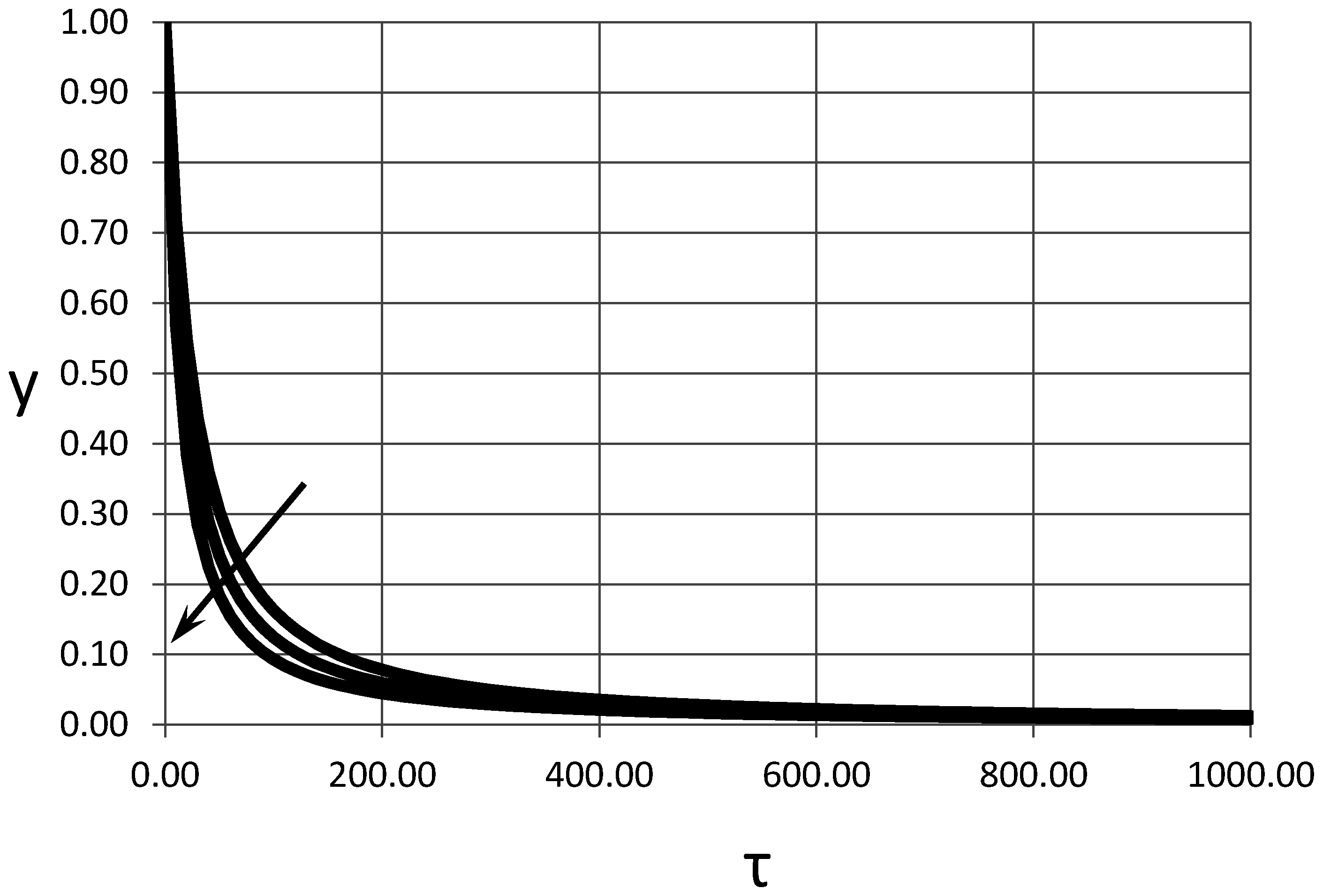
Smoke filling dynamics, according to the solutions (12)–(17) are illustrated in Figure 2 and Figure 3, where the smoke interface position and temperature of the upper layer are plotted against non-dimensional time.
Natural initial conditions for and are absent from the set (11), however, it can be shown by the means of formal asymptotic analysis that these variables have meaningful, finite limits as . For the case of this is also evident from the plot of the solution presented in Figure 3, combined with the consideration of Equation (4).
The mathematical description of the flashover mechanism identified above requires a suitable model for radiative flux emitted by the smoke layer. Radiation from the smoke layer is predominantly due to soot.
Soot emission is controlled by the absorption coefficient which can be approximated empirically as [14]:
where is the soot volume fraction (note that the numerical coefficient is dimensional).
The latter is calculated as follows:
and in non-dimensional form,
where is the soot conversion factor (soot yield) of the fuel, is the non-dimensional burning rate of the fuel, is the non-dimensional soot density.
Emissivity of the smoke (upper) layer can be written, following Drysdale [15] as:
Taking into account relations (18)–(20), smoke emissivity can be written as:
where .
Calculation of the radiative heat exchange between the smoke layer and the fuel surface requires an appropriate view factor, which is approximated here by the view factor between the long parallel planes [16].
Taking the latter into account, the radiative flux received by the material is:
(the convention here is that flux towards the material surface has a negative sign). Here, and are temperatures of the smoke and the fuel surface, respectively, is the Stefan–Boltzmann constant, is emissivity of the smoke layer, and is emissivity of the fuel surface.
Further, neglecting, in the first approximation, the effect of the fuel temperature rise on the heat exchange, the latter is reduced to:
Further, this flux is equal to that transferred into the fuel by conduction.
Evolution of the fuel surface temperature is related to the imposed flux in the well-known [17] way:
Conventional notation is used in (26) for thermal conductivity, density and specific heat of the solid material.
The same relation written in non-dimensional form (with straightforward change of the limits of integration) is:
Finally, the following equation is obtained, combining (24), (25), (27) for the evolution of the surface temperature of the virgin fuel.
where , is the fuel thermal diffusivity.
We are not aware of any experimental results for flashover development in fully sealed compartments that would allow direct comparison of the developed model. It would be important for experimentalists to obtain such data, however one should appreciate that this may well present certain experimental challenges.
The confidence in the developed model is derived from the fact that it is being developed using the two approaches that have been validated extensivley in Fire Science. The first of these is a zone description of fire development in the situation with simple compartment geometry and clear hot/cold layers stratification. This is exactly the situation considered in the present paper, and in such a situation the approach has been extensively, over several decades, validated for well-ventilated fires (see for example [12]). The minor difference in the present problem is pressure build-up in a compartment, which in fact does not alter any of the fundamental physics involved. It should also be noted that the linear pressure rise over time, obtained in the present study as Equation (12), is in exact agreement with calculations of other researchers [12].
3. Results and Discussion
To obtain results from the developed model, we adopt a fuel ignition criterion first. The empirically prescribed ignition surface temperature is, to a first approximation, a reasonable criterion adopted in fire safety science [10,15]. In the present study, the value of ignition temperature is set at which corresponds to a dimensional ignition temperature of about 750 °C. This is generally consistent with the reported values for the pilot-free ignition of cellulose containing materials.
Equation (28) allows fuel ignition (flashover) times to be predicted for various values of controlling parameters. The most important of these parameters and the sensitivity of flashover times to them is reported systematically below.
First, we analyze the problem in its final non-dimensional form.
The non-dimensional parameters that essentially control the results are , ( is a function of the latter two), , .
Non-dimensional ignition time as a function of the non-dimensional mass burning rate is presented in Figure 4.
As expected, the ignition time decreases with the increase in the mass burning rate, although the rate of decrease drops substantially as the mass burning rate increases.
Further, the influence of heat exchange conditions is illustrated in Figure 5. These are controlled by the parameter (radiation Biot number) which is essentially the ratio between the rate of the radiative heat exchange at the fuel surface and the rate of heat conduction into the solid fuel. Here, the curves are presented for different values of the parameter (which is proportional to the clearance height) which allows the influence of this parameter to be followed.
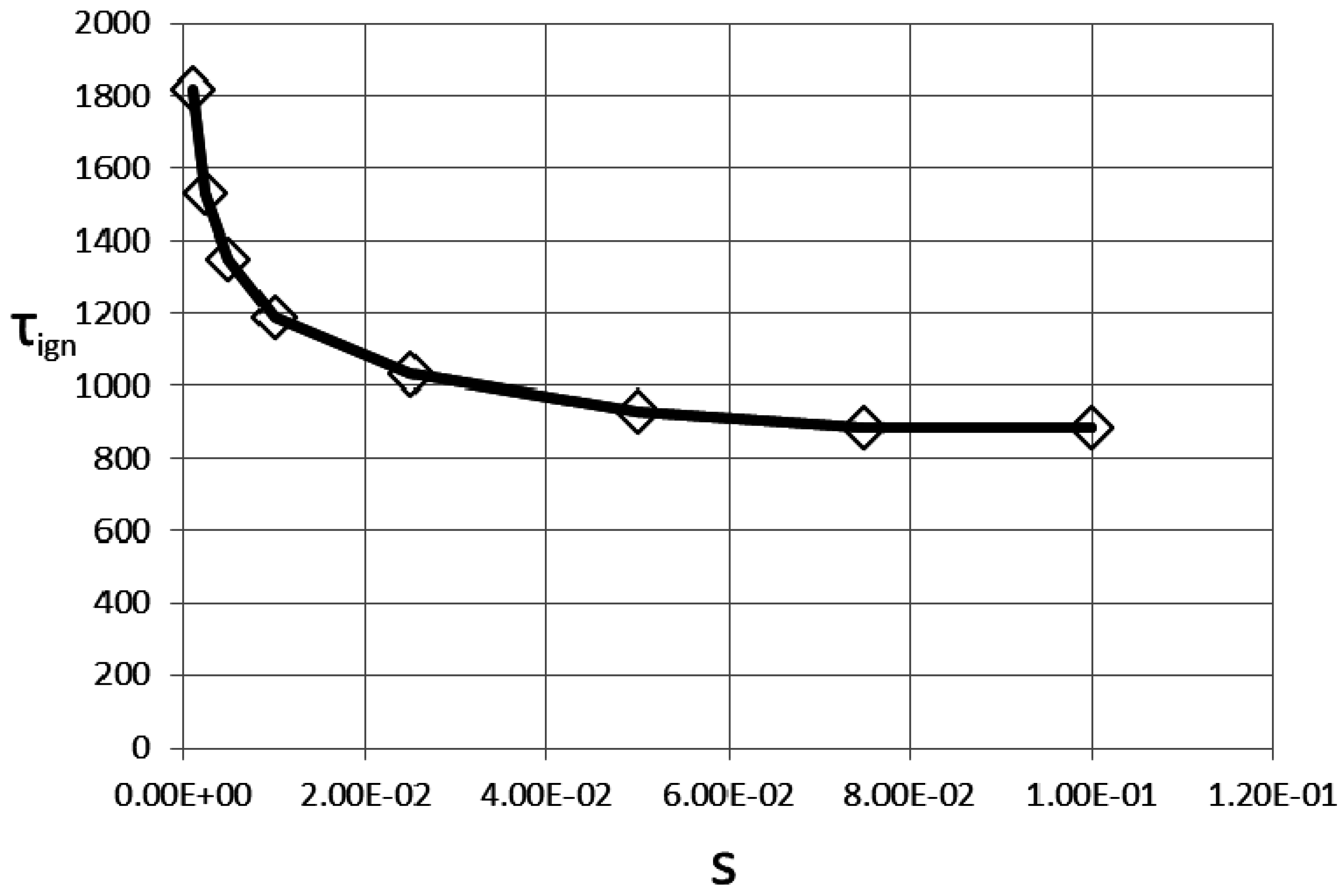
An important parameter quantifying the fuel hazard in flashover scenarios is the fuel soot yield which, to a large extent, controls the intensity of radiation emitted by the smoke layer. Dependence of the ignition time on this parameter is presented in Figure 6.
It is clear that this parameter plays a very important role in the ignition process as the dependence shown in Figure 6 is very sharp for the small values of the soot yield ().
Figure 4, Figure 5 and Figure 6 allow, in principle, full parametric dependencies of the problem to be recovered.
It is instructive, however, to observe dependencies of dimensional variables in order to get a feeling of the real physical scales involved in the process.
In particular, the curve in Figure 4 may be translated into the plot of dimensional ignition time against the HRR of the initial fire. This plot is presented in Figure 7.
Essentially, the dependence in Figure 7 shows the same trend as Figure 4. However, an important conclusion that is directly evident from Figure 7 is that even for weak initial fires (say 25–50 kW) the ignition of virgin fuel, i.e., flashover, is still occuring within a relatively short (compared to overall transportation) period of time (within 20 min).
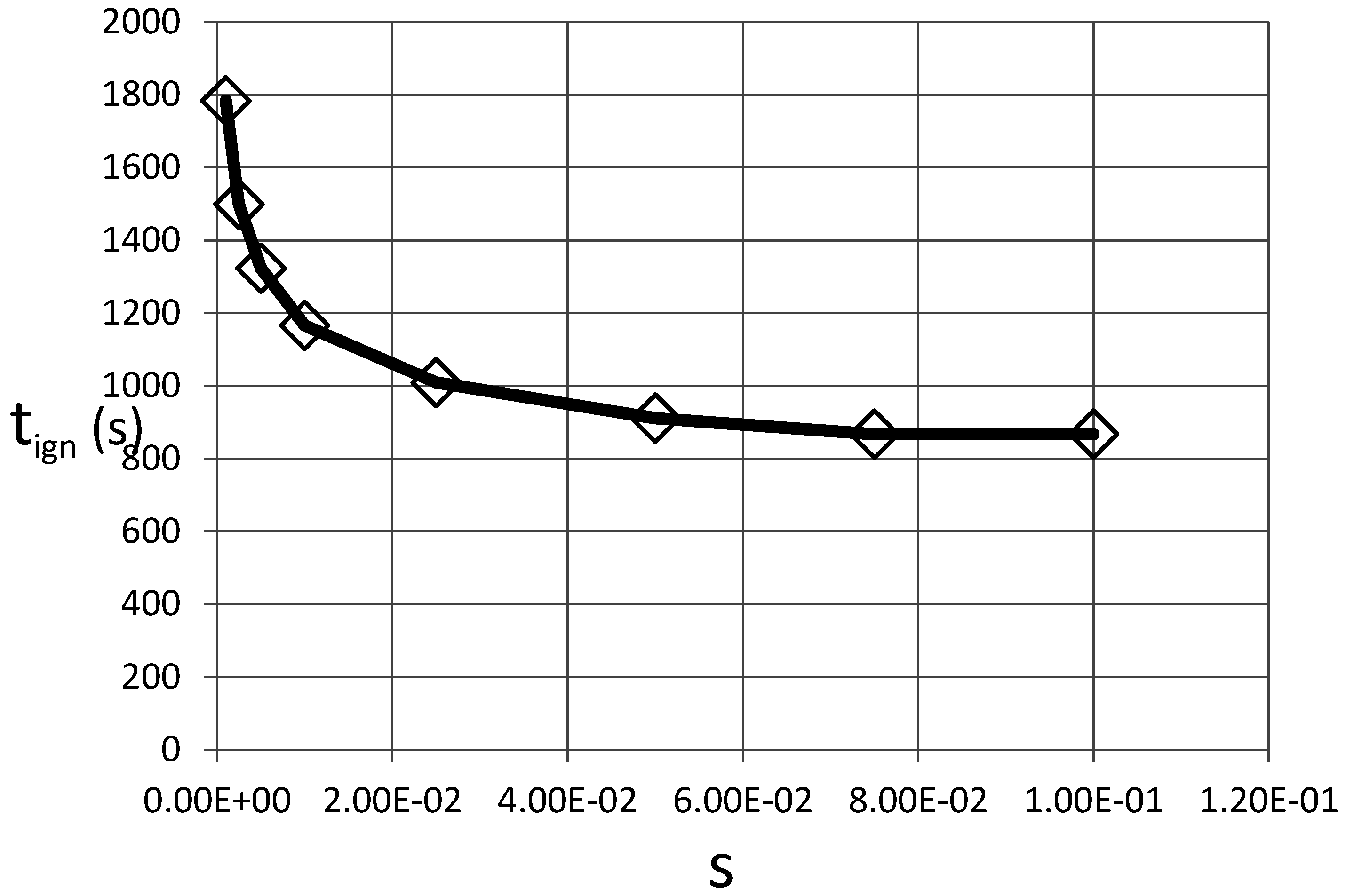
The dependence of the dimensional ignition time on soot yield also qualitatively follows the pattern for non-dimensional quantities (Figure 8).
One of the most important factors in the present problem is the consideration of the influence of the relation between the geometrical space parameters, such as fuel area and height clearance, on ignition time.
This is illustrated in Figure 9.
The results presented in Figure 9 are explained in the following way. At the same clearance height, smoke layer thickness and temperature grow slower in the cases of high fuel area as the smoke has to fill a larger volume. Consequently, radiative flux emitted by the smoke to the fuel is lower in these cases which causes a delay in ignition time.
The results presented above show that under a wide range of conditions, transition from initially localized fire to full scale flashover will occur. Time to flashover depends on a number of parameters, related to geometrical arrangements of the fuel load, as well as to the properties of transported material. The most important of these properties is fuel soot yield which controls radiative feedback from the smoke layer leading to flashover.
The significance of the developed model is that it provides, for the first time, a full quantitative estimation of the fire flashover scenario in a fully closed compartment. Key parameters that control the fire development process have been identified, and the dependencies of the process on all of these parameters have been described. The generality of the derived model means that it may be applied to a wide range of solid fuels, and over a range of their storage and/or transportation scenarios. Biofuel transportation in ship cargo compartments is just one of the straightforward examples where the present model is applicable.
Further, the developed model provides a clear path to fuel risk classification based on fire hazard.
Fire related properties are an important starting point in fuel classification based on their hazards. Murasawa and Koseki [2] propose hazard ranking of biomass fuels based on several criteria, such as “exothermic onset temperature” (a measure of how easily exothermal reactions in the material progress), heat generation rates and flammable gas generation rates. This classification is applicable to open space (or ventilated storage space) fires, which are essentially the only scenarios considered in [1,2]. Consideration of fire hazards in cargo compartments of ships requires, as shown in the present paper, additional classification. Such classification should be based on the soot yields of various fuels. Fuels with higher soot propensity will present a higher level of risks. Soot propensity ranking may be established using so-called smoke point height experiments [18,19]. This is a well-established technique based on an analysis of small scale laminar flames which are obtained by burning particular fuels.
4. Conclusions
The present study considers the fire hazard emerging from modern solid fuels transportation in ships.
The hazard originates from the ability of various modern fuels such as biomass fuels, including RDFs, to experience spontaneous ignition as a result of microbial fermentation followed by further chemical oxidation. This mechanism may lead to fire of limited size in a closed cargo compartment of a ship.
It is shown that such initial fire can lead to catastrophic flashover via a mechanism which is well-known in the theory of compartment fires. This mechanism is associated with the radiative feedback from the smoke layer formed by the initial fire.
A mathematical model which describes flashover development in a ship cargo compartment is presented. The model allows a closed form analytical solution to be obtained. In particular, a full solution for the smoke filling problem in a closed compartment is obtained. Such a full solution has never been reported in the literature.
Time to flashover is a function of several key parameters that control the dynamics of fire development. A parametric analysis of the problem is presented and the results are discussed. The principal parameter that controls fuel hazards in the present scenario is fuel soot yield, or fuel sooting propensity. This parameter controls the intensity of radiative heat exchange in the compartment, which eventually leads to flashover.
It is suggested that, in addition to existing fuel hazard rankings, fuels transported by ships should be ranked with respect to their sooting propensity. This ranking should be implemented into the regulatory framework applicable to fuel transportation by ships.
Conflicts of Interest
The author declare no conflict of interest.
Abbreviations
The following abbreviations are used in this manuscript:
| RDF | Refuse Derived Fuel |
| HRR | Heat Release Rate |
References
- Koseki, H. Evaluation of Various Solid Biomass Fuels Using Thermal Analysis and Gas Emission Tests. Energies 2011, 4, 616–627. [Google Scholar] [CrossRef]
- Murasawa, N.; Koseki, H. Investigation of Heat Generation from Biomass Fuels. Energies 2015, 8, 5143–5158. [Google Scholar] [CrossRef]
- British Marine. Available online: http://www.britishmarine.com/information/article.asp?ID=76 (accessed on 14 October 2016).
- Ship Compartment Fires. Available online: https://www.google.com.au/search?q=ship+compartment+fires&espv=2&biw=1024&bih=647&tbm=isch&imgil=Nm8N4AJ8FnUuhM%253A%253BFgIODfVbpqNK9M%253Bhttp%25253A%25252F%25252Fslideplayer.com%25252Fslide%25252F1464269%25252F&source=iu&pf=m&fir=Nm8N4AJ8FnUuhM%253A%252CFgIODfVbpqNK9M%252C_&usg=__fvOLg4xu7tEQJdfv2R0UCWYu9Wc%3D&ved=0ahUKEwj6u_uB6rLNAhXDl5QKHWeLBFkQyjcIPw&ei=feZlV7qJGMOv0gTnlpLIBQ#imgrc=6Df6DlA__1K8VM%3A (accessed on 14 October 2016).
- Guidance on the Carriage of Refuse Derived Fuel (RDF). Available online: http://www.britishmarine.com/information/article.asp?ID=76 (accessed on 14 October 2016).
- Semenov, N.N. On the Theory of Combustion Processes. J. Rus. Phys. Chem. Soc. 1928, 60, 247–250. [Google Scholar]
- Frank-Kamenetskii, D.A. Temperature Distribution in a Reactive Vessel and the Steady-state Theory of Thermal Explosion. J. Phys. Chem. 1939, 13, 738–755. [Google Scholar]
- Frank-Kamenetskii, D.A. Diffusion and Heat Transfer in Chemical Kinetics, 4th ed.; Intellect: Dolgoprudny, Russia, 2008; pp. 280–311. [Google Scholar]
- Novozhilov, V. Critical Conditions for Conjugate Thermal Explosion. Combust. Theory Model. 2008, 12, 433–449. [Google Scholar] [CrossRef]
- Novozhilov, V. Non-Linear Dynamical Model of Compartment Fire Flashover. J. Eng. Math. 2010, 67, 387–400. [Google Scholar] [CrossRef]
- Novozhilov, V. Thermal Explosion in Oscillating Ambient Conditions. Sci. Rep. 2016, 6, 29730. [Google Scholar] [CrossRef] [PubMed]
- Karlsson, B.; Quintiere, J.G. Enclosure Fire Dynamics; CRC Press: Boca Raton, FL, USA, 2000; pp. 181–225. [Google Scholar]
- Novozhilov, V. A Brief Note on the Smoke Filling Equation. Fire Saf. J. 2012, 47, 16–17. [Google Scholar] [CrossRef]
- Novozhilov, V.; Moghtaderi, B.; Fletcher, D.F.; Kent, J.H. Computational Fluid Dynamics Modelling of Wood Combustion. Fire Saf. J. 1996, 27, 69–84. [Google Scholar] [CrossRef]
- Drysdale, D. An Introduction to Fire Dynamics, 3rd ed.; Wiley: Chichester, UK, 2011; pp. 35–82. [Google Scholar]
- Incropera, F.P.; DeWitt, D.P. Fundamentals of Heat and Mass Transfer, 5th ed.; Wiley: New York, NY, USA, 2002; pp. 700–858. [Google Scholar]
- Landau, L.D.; Lifshits, E.M. Fluid Mechanics, 2nd ed.; Butterworth-Heinemann: Oxford, UK, 1987; pp. 1–541. [Google Scholar]
- Delichatsios, M.A. A Phenomenological Model for Smoke-Point and Soot Formation in Laminar Flames. Combust. Sci. Technol. 1994, 100, 283–298. [Google Scholar] [CrossRef]
- Delichatsios, M.A. Smoke Yields from Turbulent Buoyant Jet Flames. Fire Saf. J. 1993, 20, 299–311. [Google Scholar] [CrossRef]
Figure 1.
Flashover development scenario in a cargo compartment of a ship.

Figure 2.
Dynamics of the smoke layer interface in non-dimensional variables. The arrow points towards an increase of the non-dimensional heat release rate for each of the curves: ; and .
Figure 2.
Dynamics of the smoke layer interface in non-dimensional variables. The arrow points towards an increase of the non-dimensional heat release rate for each of the curves: ; and .

Figure 3.
Dynamics of the smoke (upper layer) temperature in non-dimensional variables. The arrow points towards an increase of the non-dimensional heat release rate for each of the curves: ; and .
Figure 3.
Dynamics of the smoke (upper layer) temperature in non-dimensional variables. The arrow points towards an increase of the non-dimensional heat release rate for each of the curves: ; and .
Figure 4.
Non-dimensional ignition time versus non-dimensional mass burning rate.
Figure 5.
Influence of the radiation Biot number on ignition time. Both variables are non-dimensional. The arrow points towards an increase of the parameter for each of the curves: ; and .
Figure 5.
Influence of the radiation Biot number on ignition time. Both variables are non-dimensional. The arrow points towards an increase of the parameter for each of the curves: ; and .
Figure 6.
Dependence of the ignition time on the fuel soot yield. Both variables are non-dimensional.
Figure 6.
Dependence of the ignition time on the fuel soot yield. Both variables are non-dimensional.

Figure 7.
Dimensional ignition time as a function of the dimensional initial fire HRR. ; .
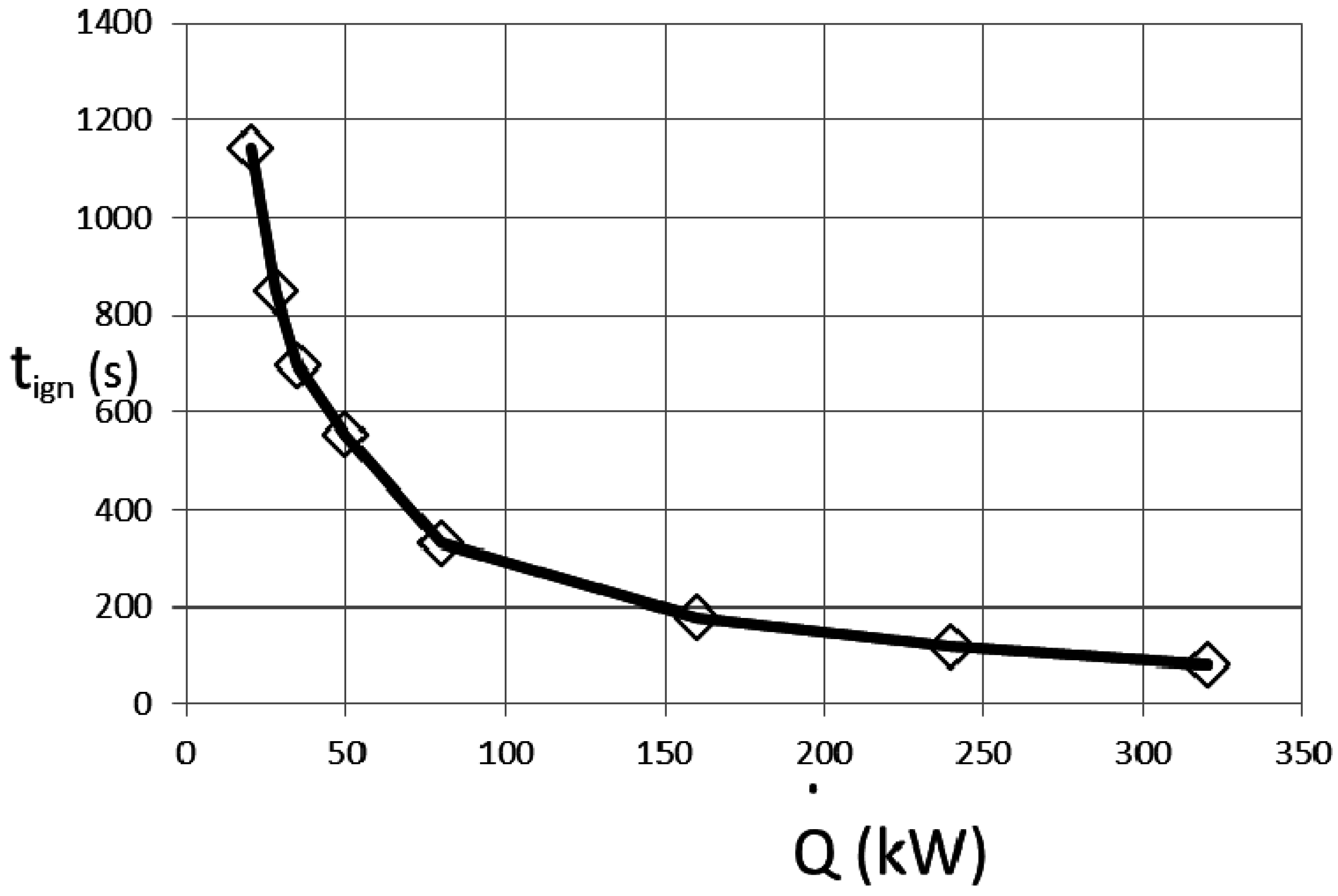
Figure 8.
Dependence of the dimensional ignition time on the non-dimensional fuel soot yield. ; .

Figure 9.
Influence of the height clearance on the dimensional ignition time. The arrow points towards an increase of the fuel area for each of the curves: ; ; and .
Figure 9.
Influence of the height clearance on the dimensional ignition time. The arrow points towards an increase of the fuel area for each of the curves: ; ; and .

© 2017 by the author; licensee MDPI, Basel, Switzerland. This article is an open access article distributed under the terms and conditions of the Creative Commons Attribution (CC-BY) license (http://creativecommons.org/licenses/by/4.0/).
Share and Cite
MDPI and ACS Style
Novozhilov, V. Fire Hazards of Some Modern Solid Fuels. Energies 2017, 10, 113. https://doi.org/10.3390/en10010113
AMA Style
Novozhilov V. Fire Hazards of Some Modern Solid Fuels. Energies. 2017; 10(1):113. https://doi.org/10.3390/en10010113
Chicago/Turabian StyleNovozhilov, Vasily. 2017. "Fire Hazards of Some Modern Solid Fuels" Energies 10, no. 1: 113. https://doi.org/10.3390/en10010113
Note that from the first issue of 2016, this journal uses article numbers instead of page numbers. See further details here.