Article

Performance Study on a Single-Screw Expander for a Small-Scale Pressure Recovery System

1
Key Laboratory of Enhanced Heat Transfer and Energy Conservation, Ministry of Education and Key Laboratory of Heat Transfer and Energy Conversion, Beijing Municipality, College of Environmental and Energy Engineering, Beijing University of Technology, Beijing 100124, China
2
School of Energy and Power Engineering, Zhengzhou University of Light Industry, No. 5 Dongfeng Road, Zhengzhou 450002, China
*
Author to whom correspondence should be addressed.
Energies 2017, 10(1), 6; https://doi.org/10.3390/en10010006
Submission received: 30 September 2016 / Revised: 1 December 2016 / Accepted: 2 December 2016 / Published: 22 December 2016
(This article belongs to the Special Issue Electric Machines and Drives for Renewable Energy Harvesting)

Abstract

:
A single-screw expander with 195 mm diameter is developed to recover pressure energy in letdown stations. An experiment system is established using compressed air as a working fluid instead of natural gas. Experiments are conducted via measurements for important parameters, such as inlet and outlet temperature and pressure, volume flow rate and power output. The influence of inlet pressure and rotational speed on the performance are also analyzed. Results indicate that the single-screw expander achieved good output characteristics, in which 2800 rpm is considered the best working speed. The maximum volumetric efficiency, isentropic efficiency, overall efficiency, and the lowest air-consumption are 51.1 kW, 83.5%, 66.4%, 62.2%, and 44.1 kg/(kW·h), respectively. If a single-screw expander is adopted in a pressure energy recovery system applied in a certain domestic natural gas letdown station, the isentropic efficiency of the single-screw expander and overall efficiency of the system are found to be 66.4% and 62.2%, respectively. Then the system performances are predicted, in which the lowest methane consumption is 27.3 kg/(kW·h). The installed capacity is estimated as 204.7 kW, and the annual power generation is 43.3 MWh. In the next stage, a pressure energy recovery demonstration project that recycles natural gas will be established within China, with the single-screw expander serving as the power machine.

Highlights

  • A single-screw expander is applied in a natural gas pressure energy recycle system.
  • Performance tests of the single screw expander are carried out by using compressed air.
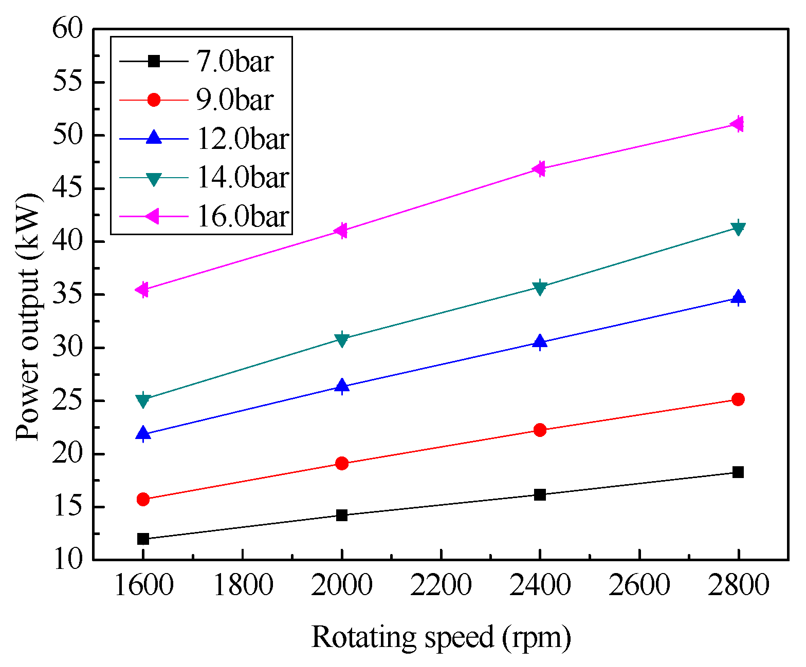
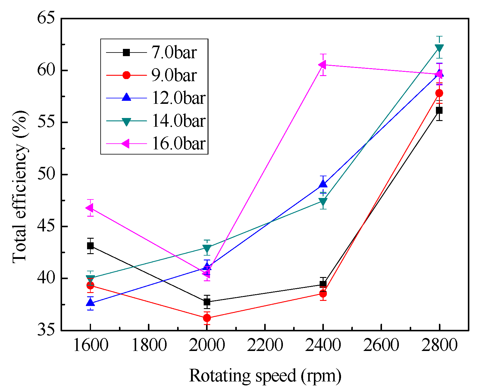
  • The maximum expander total efficiency of 62.2% is achieved at approximately 2800 rpm
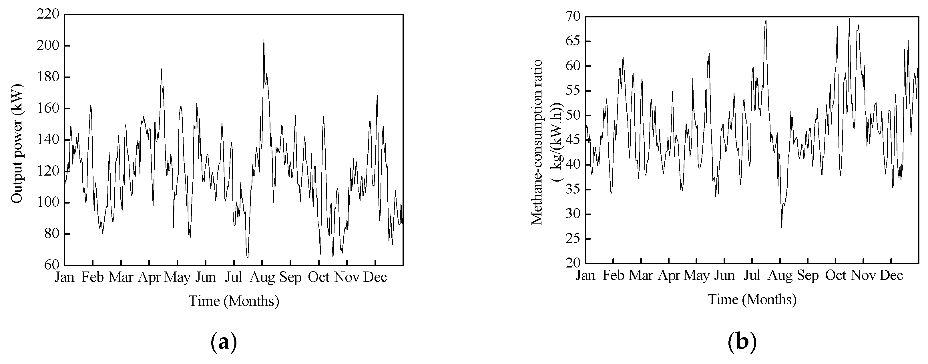
  • The installed capacity is estimated as 204.7 kW in a domestic natural gas letdown station

1. Introduction

With the development of the national economy, the demand on energy supply is also increasing by 10% annually [1]. Natural gas is currently extensively used all over the world because it is an important, clean, and secure fossil fuel. Natural gas is conveyed at high pressure with the assistance of pipelines (up to 12 MPa). The natural gas pressure must be reduced through a regulator or valves in letdown stations prior to safe utilization. Currently, the pressure energy in this process is wasted, becoming more serious when the natural gas has high expansion ratios and lower flow rates.
With the use of a commercial software to simulate power generation system [2], on the basis of the annually averaged natural gas properties and flow rates, the electricity generation from the available energy can meet all electrical demand from the refinery [3]. According to relevant data with regard to the properties and daily flow rates of the natural gas through Khorasan province (Iran) City Gate Stations in an entire year, a total of 762 MWh of electrical power could be generated [4]. A potential power generation system was proposed in Bangladesh [5], and this system was simulated with the thermo flow software. Results indicate that the exergy recovery is 96%, and the payback period is estimated as two years or so [6]. If turbo expanders were furnished for every pressure reduction station in Egypt, then the potential electricity generation capacity from the gas distribution network would amount to 110 MW [7]. Energy recovery potential has been analyzed by using energy and exergy in natural gas transport systems [8]. A turbo expander can be used to recycle the gas pressure energy. The annual recovered electrical power on City Gate Stations at Takestan, Iran was calculated to reach 1.1 GWh or so for a flow rate of 20,000 m3/h [9]. Recycling natural gas pressure energy using turbine is feasible for a system. The use the pressure exergy of natural gas for the compression of air was suggested [10]. A pilot project using a turbo expander was established at a pressure reducing station in the city of Onesti, to recover waste pressure energy [11]. Advanced numerical simulation was proposed for the thermodynamic modeling of natural gas single acting reciprocating expansion engine under various working conditions for high pressure cases. Results show that the output power increases with increasing crank radius and inlet port diameter, which also increases with increasing motor speed too [12].
A turbo expander is not only used to obtain clean electricity but is also applied in chemical processes, such as gas transportation, ethylene plants, refineries, and air separation facilities. A few pressure energy recycling projects have been recently reported and hybrid applications have also been mentioned [13].
A combined cooling, heating and power system based on an internal combustion engine was proposed for power generation, refrigeration, and domestic hot water production. Results show that primary energy efficiency, energy saving ratio, and cost saving ratio of the system can reach 0.944, 0.304, and 0.417, respectively [14]. A new approach was also presented to improve boiler thermal efficiency by integrating absorption heat pumps with natural gas boilers for waste heat recovery. This approach provided a pathway to achieve realistic high-efficiency natural gas boilers for applications [15]. A new hybrid turbo expander-fuel cell system has also been considered. In this system, natural gas was utilized to preheat the gas [16]. The cost-effectiveness of the hybrid turbo expander-fuel cell system depends on the turbo expander and fuel cell investment costs, fuel cost and electrical energy price. The increase fuel cells and turbo expander investment costs ratio increase ensures that the hybrid system can be acceptably applied in a few projects in the future [17]. The cited paper quantified the energy that could be extracted from various pressure reduction facilities using an expander coupled to an electric generator. If the coupled technologies operate at their assumed peak efficiencies, then electricity can be extracted from the pressure reduction with 75% exergetic efficiency, and hydrogen can be produced with 45% exergetic efficiency [18]. A simplified and novel method of the molten carbonate fuel cell hybrid system using a turbo expander was also proposed. An exergy analysis of the hybrid system demonstrates that an overall efficiency of up to 60% is achievable. This new technology could provide solutions and be a substitute in future energy supply systems [19]. The combined heat and power system was proposed by using a turbo expander. Results show that if a gas turbine was utilized along with the turbo expander, then the amount of electrical energy would double compared with the case in which only the turbo expander was used. The results also show that the discounted payback period is approximately 3.2 years [20]. A combined heat and power system for pressure reducing stations was investigated via modeling and optimization. Results show that the shortest payback period is 1.23 years [21].
Thermoeconomic analysis of an expansion system was applied in the natural gas transportation process. The system contains a hybrid energy generation unit that generates electricity partially from the physical exergy of pressurized natural gas, and partially from the primary energy of fuel [22]. A new approach was proposed to improve the performance of a gas turbine. The approach has been applied in one of the Khangiran refinery gas turbines. Results show that the gas turbine inlet air temperature could be reduced by 4~25 K and the performance could be improved by 1.5%~5% in ten months [23].
Expanders have been used in most waste heat and pressure energy recovery systems. The two main types of expanders can be classified as velocity-type, such as the axial turbine expander, and volume-type, such as the sliding vane expander, scroll expander, screw expander and reciprocating piston expander [24]. Normal applications include natural gas processing, petrochemical processing, air separation, pressure letdown, waste heat recovery, geothermal power generation, cryogenic refrigeration, dew point control and simulation of high altitude atmospheric conditions for turbine engine test cells [25]. Turbine expander has numerous advantages [26]; however it is generally applied to power cycles with power output greater than 50 kW, because its efficiency would be unacceptable in small scale power cycles [27]. Turbine expander has a faster rotational speed, and an excess gear box is indispensable if it is utilized in waste heat and large scale pressure energy recovery systems. Compared with velocity-type expanders, volume-type expanders are more suitable for small scale pressure and low temperature energy recovery systems, because they are characterized by lower flow rates, higher expansion ratios, and a much lower rotational speed.
Recently, the sliding vane expander has been used in the energy recovery system, mechanical power recovered was up to 1.9 kW and 4.4% of the engine shaft power [28,29]. The experimental activity on the sliding vane rotary expander as the device to convert the enthalpy of the working fluid, the overall cycle efficiency and mechanical output power achieved was close to 8% and 2 kW, respectively [30]. The scroll expander has been gaining interest as a power machine in small scale systems. This device does not require inlet or exhaust valves, and thus, the noise is reduced, and the durability of the unit is improved. Another advantage is that the rolling contacts provide a sealing effect. As a result, using a large volume of oil as a sealant is not required, and the leakage issue is relieved [31]. Compared with other volume-type expanders, scroll expanders have the most complicated geometry and may even be applied to relatively small scale power systems, down to 0.1~2 kW [32,33].
Two types of screw expanders exist: twin-screw expanders and single-screw expanders. The twin-screw expander has been extensively used in Rankine cycle systems, especially for geothermal and waste heat applications. The twin-screw expander depends on precise numerically-controlled machining to achieve a leak-resistant fit. Compared with the twin-screw expander, the single-screw expander has numerous advantages, such as long service life, balanced loading of the main-screw, high volumetric efficiency, low noise, low leakage, low vibration and simple configuration, and so on [34]. The single-screw expander can realize 1~200 kW power output range, and it is more suitable for small scale pressure energy and low temperature recovery systems. Desideri et al. described the experimental results of a small scale ORC system which utilized a single-screw expander modified from a single-screw compressor. In total, 120 steady-state experimental data points have been measured and the isentropic efficiency of the expander ranged from 27.3% to 56.35% [35].
A scheme which utilizes the pressure energy in natural gas pipelines with single-screw expander is shown in Figure 1. Any failure in the pressure power generation can be readily cut off, while the original natural gas pressure system continues to run.
Single-screw expanders with 117 and 175 mm diameter screw have been developed by our team [34,36]. On the basis of our performance experiments on these single-screw expanders, a single-screw expander with a 195 mm diameter screw was developed last year; the in volume ratio of this expander is 4.5. This single-screw expander is of CP (C-cylinder, P-planar) type. The component contains screws, gate rotors, bearings, and other normal parts. Polytetrafluoroethylene (PTFE) is used as the material for the gate rotors to reduce the friction resistance between screw and gate rotors. A balance hole connects the high pressure leakage room with the low pressure discharge chamber of the expander. This hole is drilled on the shell, which is quite different from the balance hole drilled on the screw or main shaft. Moreover, the gaps between the screw and the shell and between the gate rotors and the groove have been optimized.
The main task of this paper is to describe the performance test conducted on this prototype. Meanwhile, the effects of rotational speed and inlet pressure of the working fluid on the prototype performance were also studied. Finally, the scale of the recoverable natural gas pressure energy in a domestic natural letdown station was predicted.

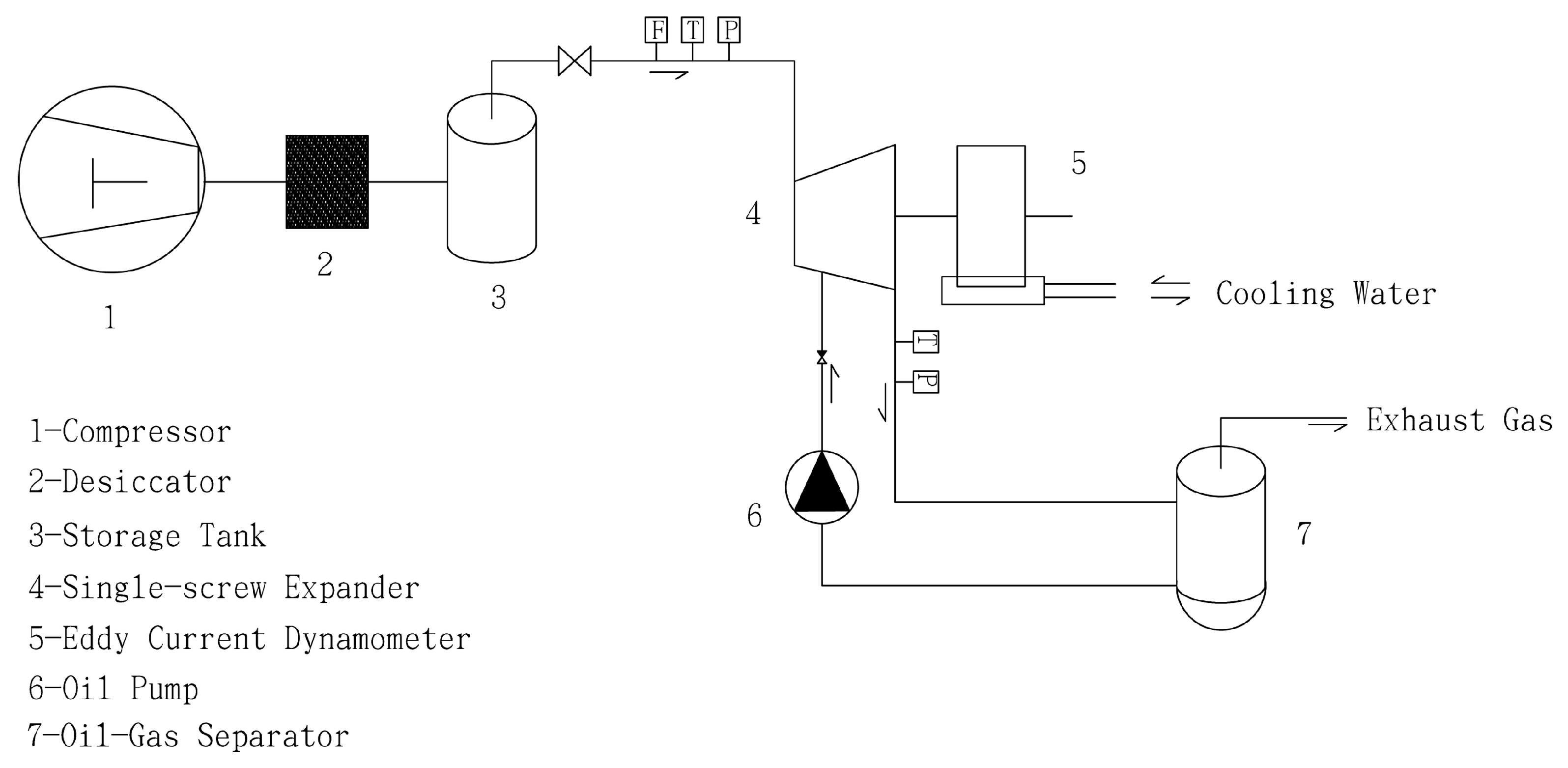
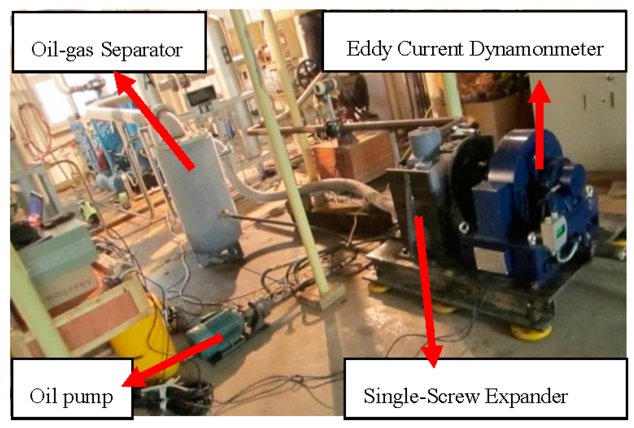
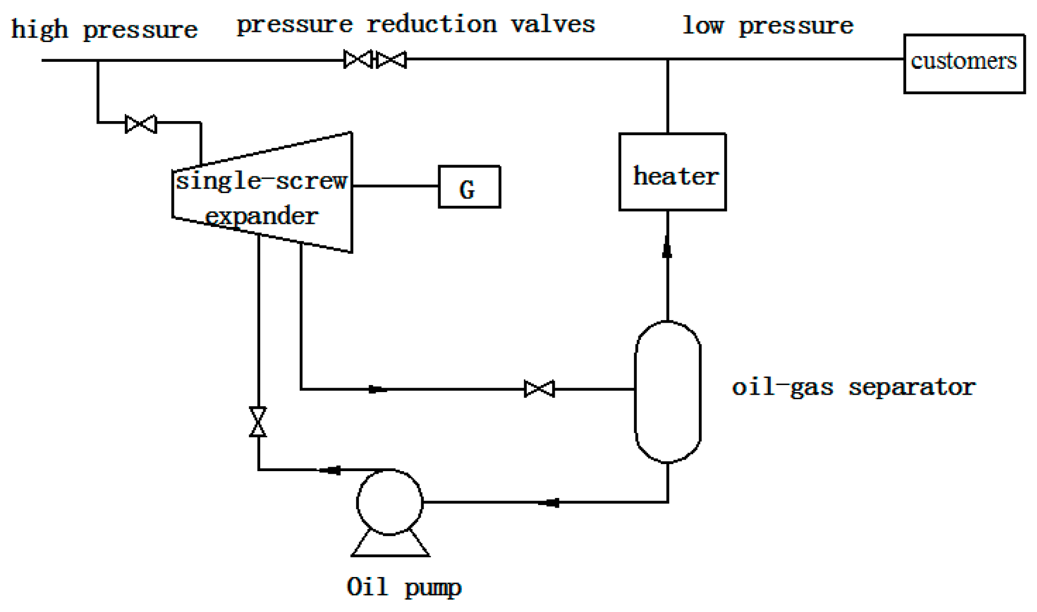
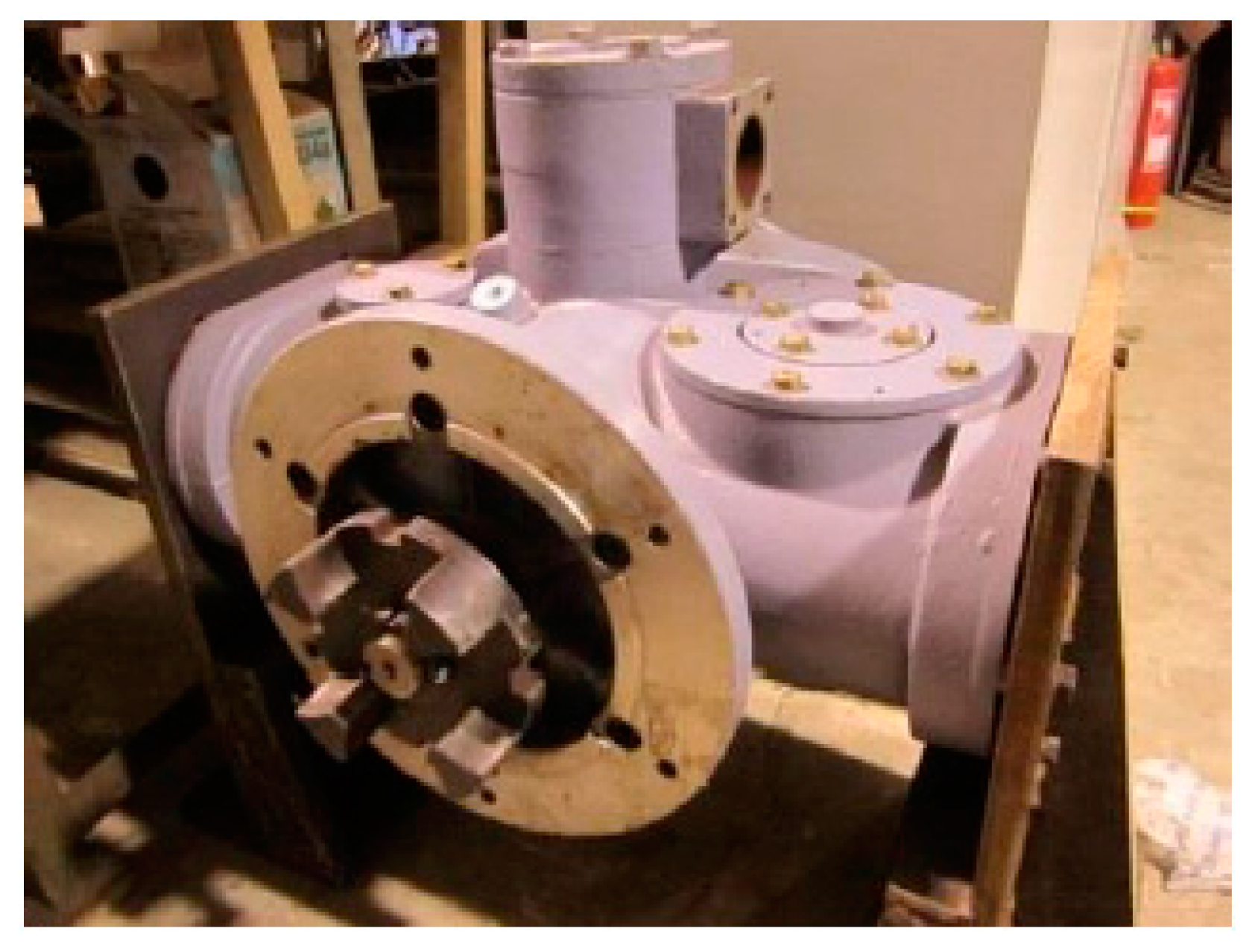
2. Experimental System

The key components of single-screw expanders are one screw and two gate rotors, which create a working chamber with the shell, as shown in Figure 2. As the screw and gate rotors rotate, the working chamber becomes bigger until it connects with the exit chamber. Figure 3 shows a photo of this prototype, and Table 1 illustrates the parameters of the prototype.
Considering the risk in handling natural gas, compressed air is used as the working fluid in the experiment instead of natural gas. The experimental system is illustrated in Figure 4. An air compressor provided high pressure air to the storage tank, which served as the stable gas source in the test. Compressed air flowed at a preset flow rate with different pressures from the storage tank and entered the single-screw expander by adjusting the inlet valve. Exhaust gas was discharged outside of the room. Through an eddy current dynamometer for the load, the power output was converted to heat, which was carried away by cooling water. Oil is injected into the expander and mixed with air to lubricate and seal. In the oil-gas separator, oil is separated from the exhaust gas and stored in the lower part of the separator. The parameters of working fluid, including intake volume flow, inlet and outlet pressure, and inlet and outlet temperature, as well as the performance parameters of the single-screw expander, such as torque, power output, and rotational speed, were obtained. A photo of the experimental platform is shown in Figure 5.
During the experiment, two pressure transmitters of the SMP131 type were used with a current output of 0~20 mA. The measurement range of one is 0~1.0 MPa, the other is 0~3.0 MPa and their accuracy is 0.5%. Two temperature transmitters of LG200 were used with a current output of 0~20 mA. Their measurement ranges are 0~50 °C and −100~50 °C respectively, both with an accuracy of 0.5%. The pressure transmitters and temperature transmitters are supplied by Leeg Instruments Co., Ltd. (Shanghai, China). A vortex flow-meter of FFM63 type provided by Floworld Meter Co., Ltd. (Shanghai, China) was used with current output of 4~20 mA. The measurement range is 50~280 m3/h, and its accuracy level is 1.5%. The torque transducer model used has the measurement ranges of 0~160 N·m and 0~10,000 r/min, which is manufactured by Xiangyi Dynamic Test Instrument Co., Ltd. (Changsha, China) and the measurement accuracy of torque is ±0.2%~0.4% FS, and that of rotational speed is ±1 r/min.

3. Data Processing

The main indexes for evaluating the performance of single-screw expanders are volume efficiency η V , isentropic efficiency η s , mechanical efficiency η M , total efficiency η t , and air-consumption ratio d.
(1) Volumetric efficiency
Volume efficiency is an important parameter of single-screw expanders. For single-screw expander, the intake pressure is higher than the discharge pressure, and working fluid leaks though gaps from inlet chambers to discharge rooms. The actual flow rate through the expander is thus increased, and it may become larger than the theoretical flow rate. Therefore it is reasonable to define the volume efficiency of expander as
η V = q V t h / q V × 100 %
where, q V t h is theoretical volume flow rate through the expander, and q V is the measured one. It is obvious that η V is probably smaller than 100% for positive-displacement expanders. A small value of volume efficiency denotes an expander with serious leakage.
(2) Isentropic efficiency
Isentropic efficiency is an important parameter for evaluating the effect of internal irreversible losing single-screw expanders during the isentropic process, which is defined as the ratio of the actual specific enthalpy drop to the isentropic specific enthalpy drop for the same inlet state and the same outlet pressure.
η s = Δ h / Δ h s × 100 %
where Δh is the actual specific enthalpy drop, and Δhs is the isentropic specific enthalpy drop.
(3) Mechanical efficiency
Mechanical efficiency is an important parameter for evaluating the single-screw expander during the expansion process, which is defined as the ratio of power output drop to the total measured enthalpy drop.
η M = P e / Δ h × 100 %
where, Pe is the power output of the single-screw expander, and Δh is the actual specific enthalpy drop.
(4) Total efficiency
Total efficiency is the ratio of the power output to the enthalpy drop of the working fluid in an ideal isentropic process, which is defined by
η t = P e / ( m Δ h s ) × 100 %
where, Pe is the power output of the single-screw expander, m is the mass flow, and Δhs is the specific enthalpy drop.
(5) Air-consumption ratio
Air-consumption ratio is another important parameter for evaluating the economical efficiency of this prototype, and is defined as
d = m / P e

4. Experimental Performances Analysis

Performance tests were conducted for different inlet pressures and rotating speeds, ranging from 7 bar to 16 bar and from 1600 rpm to 2800 rpm, respectively.

4.1. Power Output

The power output Pe is an important parameter for evaluating the performance of single-screw expanders. The effects of rotational speed on power output are shown in Figure 6. As seen from this figure, the power output increases with increases of rotational speed and inlet pressure, and the maximum of the power output is 51.1 kW (the maximum error is 0.2 kW) obtained at the condition of 16 bar and 2800 rpm. However, the increase rate of the power output with increase of inlet pressure is faster than that with increase of rotational speed. This shows that, with the increase of rotational speed, the power consumption of the friction loss between the screw and the shell increases gradually, which leads to the slow growth of the output power. Figure 6 illustrates that the influence of inlet pressure is bigger than that of rotational speed.

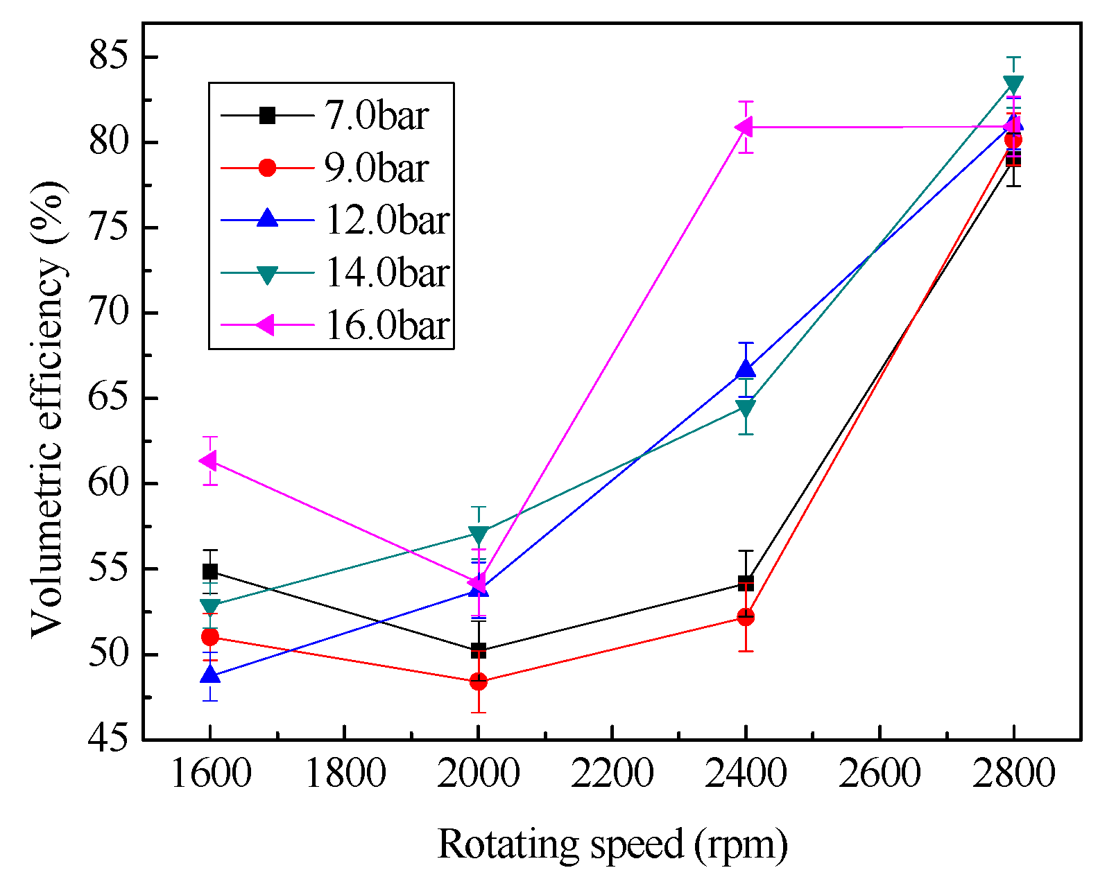
4.2. Volumetric Efficiency

Volume efficiency is another important parameter of single-screw expanders. Figure 7 shows the changes of the volumetric efficiency versus rotational speed. Overall, at a different pressure, the volumetric efficiency reaches a maximum value of 83.5% (the maximum error is 1.4%). It can be seen that in a certain range of pressure, the rotational speed 2800 rpm of a single-screw expander is more conducive to the formation and stability of oil slick, and that the amount of gas leakage maybe reaches the minimum, so that the volume efficiency has the highest value. Theoretically, the volume efficiency should remain unchanged at a certain constant rotational speed no matter what the inlet pressure is, because the basic volume of the single-screw expander is invariant. This conclusion is validated by Figure 8. That is to say, the operation was steady in the case of 2800 rpm. The corresponding parameters can be used as the performance parameters of this prototype.

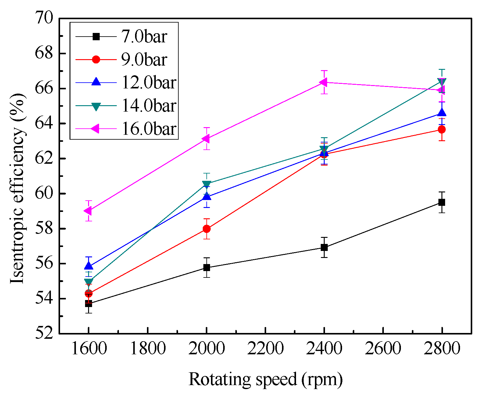
4.3. Isentropic Efficiency

The variation of isentropic efficiency with changes of rotational speed is shown in Figure 8. The influencing factors on isentropic efficiency are the irreversible losses in the system, including internal leakage, eddy current, friction and so on. From Figure 8, under the same inlet pressure, the isentropic efficiency increases with the increase of rotational speed. At the maximum value of 66.4% (the maximum of error is 0.7%) in the case of 2800 rpm, with the increase of rotational speed, gas flow increases, gas leakage ratio decreased, and the friction loss is not sufficient to affect the decline of outlet temperature, thus increasing the adiabatic efficiency.
Under the same rotating speed, the isentropic efficiency first increases with the increase of inlet pressure. However, when inlet pressure increased to a certain value, the isentropic efficiency began to decline. This is because the pressure increases, the gas flow gradually increased, but the corresponding reduction in the proportion of gas leakage, and thus increase the adiabatic efficiency. When the pressure exceeds a certain value, since the increase of inlet pressure causes the increase of internal leakage correspondingly, which leads to the increase of outlet temperature, and thus the isentropic efficiency declines. It shows that the best performance of single-screw expander happens at 2800 rpm, at which the irreversible loss achieves at the minimum.

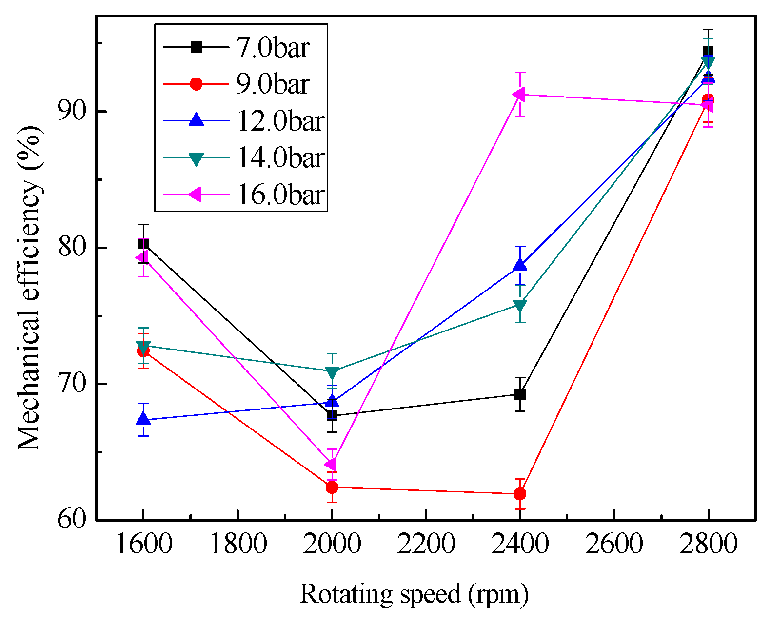
4.4. Mechanical Efficiency

Mechanical efficiency is an important parameter for evaluating the performance of the single-screw expander during the expansion process. The variation of mechanical efficiency with rotational speed is shown in Figure 9. At the same pressure, when the rotational speed is lower than 2000 rpm, with the increase of rotational speed, gas flow increases, gas leakage ratio decreased, but the rate of friction loss is greater than the power output, so that the mechanical efficiency is reduced. When the rotational speed is 2000–2800 rpm, the friction loss rate is less than the rate of the power output, so the mechanical efficiency increases, reaching the maximum value. From Figure 9, under the different inlet pressure, at the rotating speed of 2800 rpm, the mechanical efficiency up to the maximum value of 93.7% (the maximum error is 1.7%), it can illustrate that the best performance of a single-screw expander is achieved at 2800 rpm.

4.5. Total Efficiency

The variations of total efficiency with changing rotational speed are shown in Figure 10, the total efficiency at 2800 rpm is better than that at other speed under the same inlet pressure, and the maximum of total efficiency reaches 62.2% (the maximum error is 1.0%) under the condition of 14.0 bar and 2800 rpm. Figure 10 shows that the total efficiency increases with the increase of rotational speed. The total efficiency reaches a maximum at 2800 rpm under the same inlet pressure. It again illustrates that the best performance of the single-screw expander is achieved at 2800 rpm, and that the sealing performance and friction loss of the expansion machine achieves an optimal value, which makes the total efficiency reach the maximum at a speed of 2800 rpm.

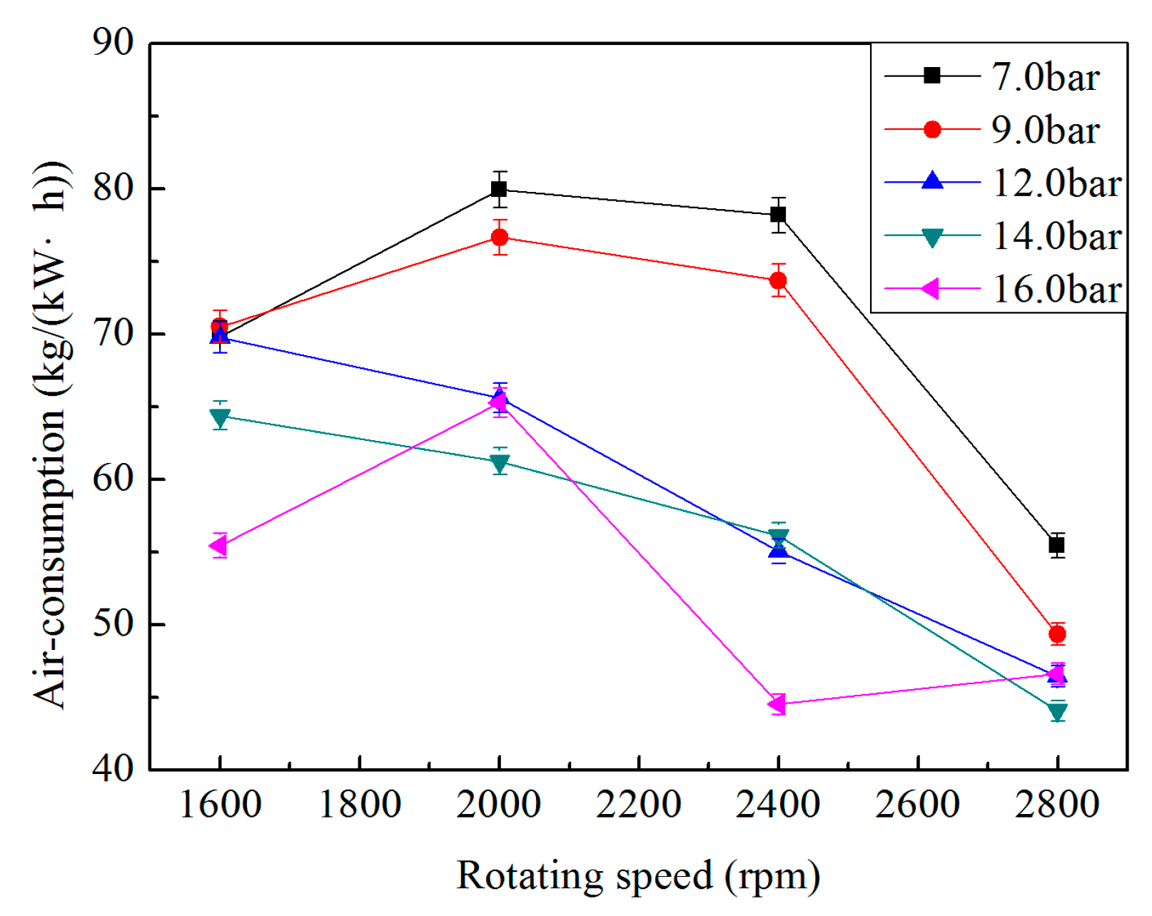
4.6. Air Consumption

Figure 11 shows the variations of air consumption with changing rotational speed. From Figure 11, the air-consumption decreases with the increase of the inlet pressure at 2000 rpm, 2800 rpm and 3200 rpm, and there is the lowest air-consumption when the rotating speed is at 2800 rpm. It proves that the best economic performance of single-screw expander is obtained at 2800 rpm, at which the air consumption is also the lowest, i.e., 44.1 kg/(kW·h).

5. Prediction

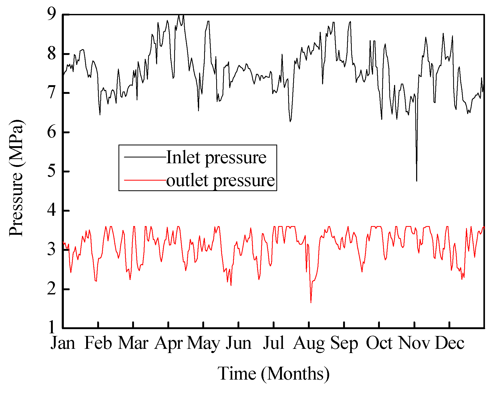
5.1. Operational Parameters

We then proceed to predict the scale of the recoverable natural gas pressure energy in the Jiyuanzhongyu natural gas letdown station in Henan province in 2014. The single-screw expander with 195 mm diameter is used as the power machine, and the inlet/outlet pressure of natural gas in the letdown station are shown in Figure 12. As seen in Figure 12, the maximum, minimum and average inlet/outlet pressures are 9.04/3.60 MPa, 4.75/1.62 MPa and 7.57/3.12 MPa respectively.

5.2. Assumptions

The following hypotheses are adopted in the analysis of the natural gas pressure energy recovery system:
(1) The natural gas can be defined as pure methane because of the high concentration of methane in the natural gas components.
(2) The inlet/outlet pressure and the inlet temperature of the Jiyuanzhongyu natural gas letdown station are the inlet/outlet pressure and inlet temperature of the single-screw expander respectively.
(3) The inlet volume flow rate of natural gas is assumed to be 110 m3/h, which is the average inlet volume flow rate in the experiment.
(4) The isentropic efficiency of the single-screw expander and overall efficiency of the system is taken as 66.4% and 62.2%, respectively.

5.3. Predictions

Figure 13 shows the prediction curves of output power and methane-consumption ratio. The output power of April and August is larger, and that of February, July and November is small can be seen from Figure 13a; the methane consumption of February, July and November is larger, and that of April and August is small can be seen from Figure 13b; The predicted parameters are summarized in Table 2.
Based on the predicted results in Table 2, it is concluded that if the natural gas energy could have been used to generate electricity and the lowest methane consumption was 27.3 kg/(kW·h), the installed capacity can be estimated as 204.7 kW, and the annual power generation would be a total of 43.3 MW·h in 2014.

6. Conclusions

The pressure energy recovery system that will be applied in the Jiyuanzhongyu natural gas letdown station in Henan province was analyzed through experiments on a pressure recovery system using a single-screw expander. The following conclusions can be drawn.
The single-screw expander achieved good output at 2800 rpm. The greatest power output, the maximum volumetric efficiency, the maximum of isentropic efficiency and overall efficiency were 51.1 kW, 83.5%, 66.4% and 62.2% respectively.
When the pressure energy recovery system with a single-screw expander is applied in a domestic natural gas letdown station, the isentropic efficiency of the single-screw expander and overall efficiency of the system are 66.4% and 62.2%, respectively. The lowest methane consumption is 27.3 kg/(kW·h), the installed capacity is estimated as 204.7 kW and the annual power generation would be a total of 43.3 MWh. Thus, the single-screw expander has great prospects in small-scale waste heat pressure energy recovery systems, as well as in new and renewable energy applications.

Acknowledgments

The authors acknowledge the financial support provided by the International Natural science foundation of china (Grant Numbers 51361135702) and the National Basic Research Program of China (Grant Numbers 2013CB228306). Also, the authors gratefully acknowledge the support of data provided by the Compressor Dept. Petro china West East Gas Pipeline Company.

Author Contributions

Guoqiang Li wrote the paper. Guoqiang Li, Yuting Wu and Yeqiang Zhang conceived and designed the experiments; Guoqiang Li and Yeqiang Zhang performed the experiments; Ruiping Zhi, Jingfu Wang and Chongfang Ma revised the paper and provided useful suggestions; all authors read and approved the manuscript.

Conflicts of Interest

The authors declare no conflict of interest.

Nomenclature

d air-consumption ratio (kg/kW·h)
q V t h theoretical volume flowrate (m3/h)
q V measured volume flowrate (m3/h)
Δ h actual specific enthalpy drop (kJ/kg)
Δ h s isentropic enthalpy drop (kJ/kg)
Pepower output (kW)
m mass flow (kg/h)
n rotate speed (r/min)
V 0 maximum basic volume (m3)
Z 1 groove number of single-screw rotor

Greek Symbol

η s isentropic efficiency (%)
η M mechanical efficiency (%)
η t total efficiency (%)
η V volumetric efficiency (%)

Subscripts

M mechanical energy
sisentropic
ttotal
V volume
0ambient condition

References

  1. Lin, W.; Zhang, N.; Gu, A. LNG (liquefied natural gas): A necessary part in China’s future energy infrastructure. Energy 2010, 35, 4383–4391. [Google Scholar] [CrossRef]
  2. Atik, K. Thermoeconomic optimization in the design of thermoelectric cooler. In Proceedings of the 5th International Advanced Technologies Symposium, Karabuk, Turkey, 13–15 May 2009; pp. 1775–1778.
  3. Farzaneh-Gord, M.; Deymi-Dashtebayaz, M. Recoverable energy in natural gas pressure drop stations: A case study of the Khangiran gas refinery. Energy Explor. Exploit. 2008, 26, 71–82. [Google Scholar] [CrossRef]
  4. Farzaneh-Gord, M.; Hashemi, S.; Sadi, M. Energy destruction in Iran’s natural gas pipe line network. Energy Explor. Exploit. 2007, 25, 393–406. [Google Scholar] [CrossRef]
  5. Mansoor, S.A.; Mansoor, A. Power generation opportunities in Bangladesh from gas pressure reducing stations. In Proceedings of the 3rd International Conference on Electrical & Computer Engineering, Dhaka, Bangladesh, 28–30 December 2004; p. 3.
  6. Seresht, R.T.; Jalalabadi, H.K.; Rashidian, B. Retrofit of Tehran City Gate Station (CGS No. 2) by Using Turboexpander. In Proceedings of the ASME 2010 Power Conference, American Society of Mechanical Engineers, Chicago, IL, USA, 13–15 July 2010; pp. 207–212.
  7. Elsobki, M.S.; El-Salmawy, H.A. Power generation using recovered energy from natural gas networks. In Proceedings of the 17th International Conference on Electricity Distribution, Barcelona, Spain, 12–15 May 2003.
  8. Kostowski, W. The possibility of energy generation within the conventional natural gas transport system. Strojarstvo 2010, 52, 429–440. [Google Scholar]
  9. Rezaie, N.Z.; Saffar-Avval, M. Feasibility Study of Turbo Expander Installation in City Gate Station. In Proceedings of the 25th International Conference on Efficiency, Cost, Optimization and Simulation of Energy Conversion Systems and Processes, Perugia, Italy, 26–29 June 2012; p. 47.
  10. Bisio, G. Thermodynamic analysis of the use of pressure exergy of natural gas. Energy 1995, 20, 161–167. [Google Scholar] [CrossRef]
  11. Andrei, I.; Valentin, T.; Cristina, T.; Niculae, T. Recovery of Wasted Mechanical Energy from the Reduction of Natural Gas Pressure. Procedia Eng. 2014, 69, 986–990. [Google Scholar] [CrossRef]
  12. Gord, M.F.; Jannatabadi, M. Simulation of single acting natural gas Reciprocating Expansion Engine based on ideal gas model. J. Nat. Gas Sci. Eng. 2014, 21, 669–679. [Google Scholar] [CrossRef]
  13. Daneshi, H.; Khorashadi Zadeh, H.; Lotfjou Choobari, A. Turboexpander as a distributed generator. In Proceedings of the 2008 IEEE Power and Energy Society General Meeting—Conversion and Delivery of Electrical Energy in the 21st Century, Pittsburgh, PA, USA, 20–24 July 2008; p. 7.
  14. Wang, J.; Wu, J.; Zheng, C. Simulation and evaluation of a CCHP system with exhaust gas deep-recovery and thermoelectric generator. Energy Convers. Manag. 2014, 86, 992–1000. [Google Scholar] [CrossRef]
  15. Qu, M.; Abdelaziz, O.; Yin, H. New configurations of a heat recovery absorption heat pump integrated with a natural gas boiler for boiler efficiency improvement. Energy Convers. Manag. 2014, 87, 175–184. [Google Scholar] [CrossRef]
  16. Howard, C.; Oosthuizen, P.; Peppley, B. An investigation of the performance of a hybrid turboexpander-fuel cell system for power recovery at natural gas pressure reduction stations. Appl. Therm. Eng. 2011, 31, 2165–2170. [Google Scholar] [CrossRef]
  17. Darabi, A.; Shariati, A.; Ghanaei, R.; Soleimani, A. Economic assessment of the hybrid turbo expander-fuel cell gas energy extraction plant. Turk. J. Electr. Eng. Comput. Sci. 2016, 24, 733–745. [Google Scholar] [CrossRef]
  18. Maddaloni, D.J.; Rowe, A.M. Natural gas exergy recovery powering distributed hydrogen production. Int. J. Hydrogen Energy 2007, 32, 557–566. [Google Scholar] [CrossRef]
  19. Rashidi, R. Thermodynamic Analysis of Hybrid Molten Carbonate Fuel Cell Systems; University of Ontario Institute of Technology: Oshawa, ON, Canada, 2008. [Google Scholar]
  20. Eftekhari, H.; Akhlaghi, K.; Farzaneh-Gord, M.; Khatib, M. A Feasibility Study of Employing an Internal Combustion Engine and a Turbo-expander in a CGS. Int. J. Chem. Environ. Eng. 2011, 2, 343–349. [Google Scholar]
  21. Sanaye, S.; Nasab, A.M. Modeling and optimizing a CHP system for natural gas pressure reduction plant. Energy 2012, 40, 358–369. [Google Scholar] [CrossRef]
  22. Wojciech, S.U.; Kostowski, J. Thermoeconomic assessment of a natural gas expansion system integrated with a co-generation unit. Appl. Energy 2013, 101, 58–66. [Google Scholar]
  23. Farzaneh-Gord, M.; Deymi-Dashtebayaz, M. A new approach for enhancing performance of a gas turbine (case study: Khangiran refinery). Appl. Energy 2009, 86, 2750–2759. [Google Scholar] [CrossRef]
  24. Qiu, G.; Liu, H.; Riffat, S. Expanders for micro-CHP systems with organic Rankine cycle. Appl. Therm. Eng. 2011, 31, 3301–3307. [Google Scholar] [CrossRef]
  25. Bloch, H.; Soares, C. Turboexpanders and Process Applications; Gulf Professional Publishing: Boston, MA, USA, 2001. [Google Scholar]
  26. Pei, G.; Li, Y.; Li, J.; Ji, J. An experimental study of a micro high-speed turbine that applied in Organic Rankine cycle. In Proceedings of the Asia-Pacific Power and Energy Engineering Conference (APPEEC), Chengdu, China, 28–31 March 2010; pp. 1–4.
  27. Peterson, R.; Wang, H.; Herron, T. Performance of a small-scale regenerative Rankine power cycle employing a scroll expander. Proc. Inst. Mech. Eng. Part A 2008, 222, 271–282. [Google Scholar] [CrossRef]
  28. Bianchi, G. Exhaust Waste Heat Recovery in Internal Combustion Engines. Ph.D. Thesis, University of L’Aquila, L’Aquila, Italy, March 2015. [Google Scholar]
  29. Cipollone, R.; Contaldi, G.; Bianchi, G.; Murgia, S. Energy Recovery Using Sliding Vane Rotary Expander. In Proceedings of the 8th International Conference on Compressors and their Systems, London, UK, 9–10 September 2013; pp. 183–194.
  30. Cipollone, R.; Bianchi, G.; Battista, D.D.; Contaldi, G.; Murgia, S. Mechanical Energy Recovery from Low Grade Thermal Energy Sources. Energy Procedia 2014, 45, 121–130. [Google Scholar] [CrossRef]
  31. Wang, H.; Peterson, R.; Herron, T. Experimental performance of a compliant scroll expander for an organic Rankine cycle. Proc. Inst. Mech. Eng. Part A 2009, 223, 863–872. [Google Scholar] [CrossRef]
  32. Lemort, V.; Quoilin, S.; Cuevas, C.; Lebrun, J. Testing and modeling a scroll expander integrated into an Organic Rankine Cycle. Appl. Therm. Eng. 2009, 29, 3094–3102. [Google Scholar] [CrossRef]
  33. Lemort, V.; Declaye, S.; Quoilin, S. Experimental characterization of a hermetic scroll expander for use in a micro-scale Rankine cycle. Proc. Inst. Mech. Eng. Part A 2012, 226, 126–136. [Google Scholar] [CrossRef]
  34. Wang, W.; Wu, Y.; Ma, C.; Liu, L.; Yu, J. Preliminary experimental study of single-screw expander prototype. Appl. Therm. Eng. 2011, 31, 3684–3688. [Google Scholar] [CrossRef]
  35. Desideri, A.; den Broek, M.; Gusev, S.; Lemort, V.; Quoilin, S. Experimental Campaign and Modeling of a Low-capacity Waste Heat Recovery System Based on a Single-screw Expander. In Proceedings of the 22nd International Compressor Engineering Conference, West Lafayette, IN, USA, 14–17 July 2014.
  36. He, W.; Wu, Y.; Peng, Y.; Zhang, Y.; Ma, C.; Ma, G. Influence of intake pressure on the performance of single-screw expander working with compressed air. Appl. Therm. Eng. 2013, 51, 662–669. [Google Scholar] [CrossRef]
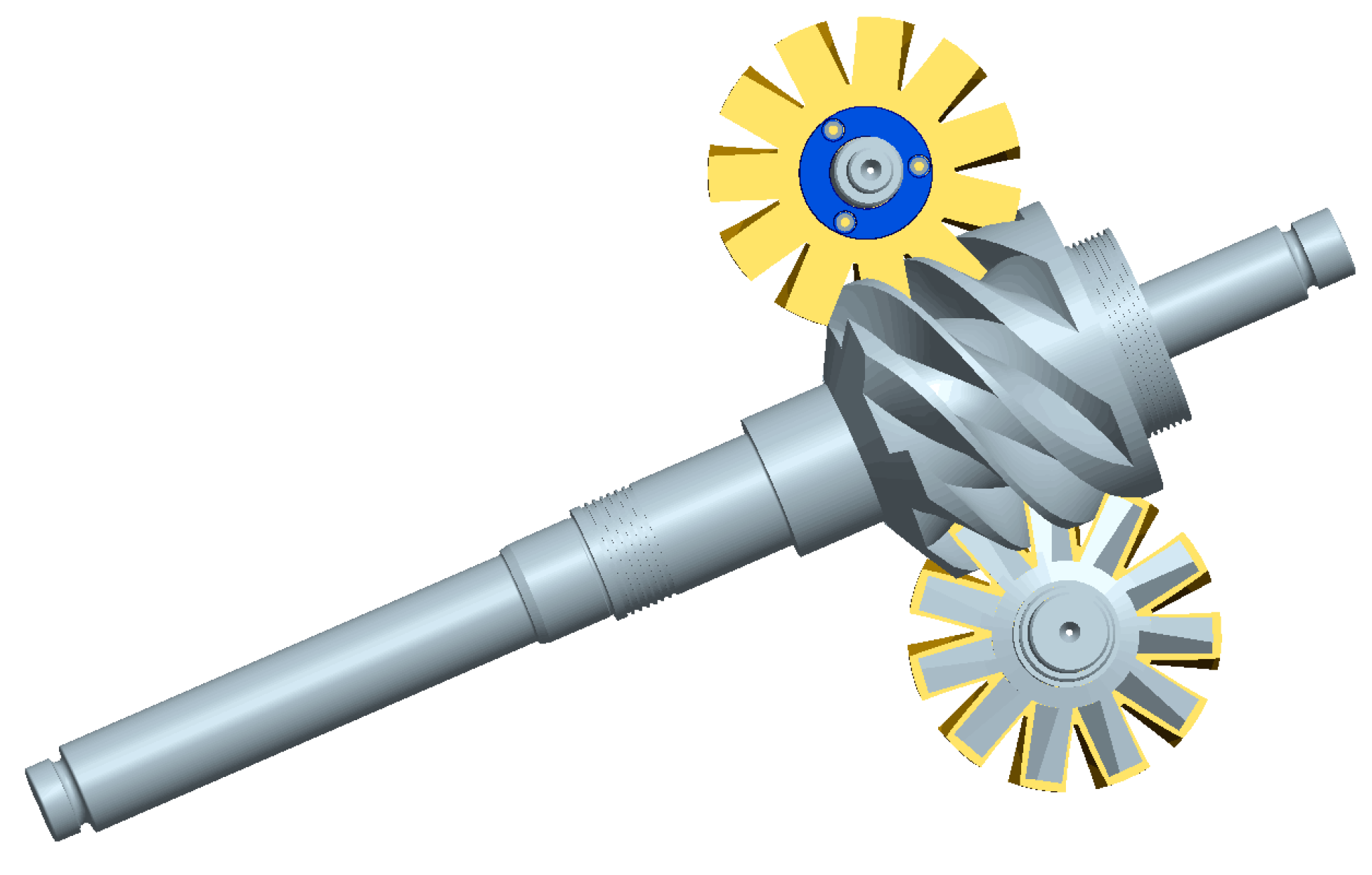
Figure 1. Schematic view of a basic high pressure natural gas pipeline with single-screw expander.
Energies 10 00006 g001
Figure 2. Three-dimensional structure of the single-screw expander.
Energies 10 00006 g002
Figure 3. Photo of the single-screw expander prototype.
Energies 10 00006 g003
Figure 4. Schematic diagram of the experimental system.
Energies 10 00006 g004
Figure 5. Experimental platform.
Energies 10 00006 g005
Figure 6. Power output versus rotating speed.
Energies 10 00006 g006
Figure 7. Volumetric efficiency versus rotating speed.
Energies 10 00006 g007
Figure 8. Isentropic efficiency versus rotating speed.
Energies 10 00006 g008
Figure 9. Mechanical efficiency versus rotating speed.
Energies 10 00006 g009
Figure 10. Total efficiency versus rotating speed.
Energies 10 00006 g010
Figure 11. Air-consumption versus rotating speed.
Energies 10 00006 g011
Figure 12. Inlet/outlet pressure of natural gas during 2014.
Energies 10 00006 g012
Figure 13. Predicted parametric curves of output power (a) and methane-consumption ratio (b).
Energies 10 00006 g013
Table 1. Parameters of the prototype.
ParameterDiameter of the Screw (mm)Groove Number of the ScrewDiameter of the Gate Rotor (mm)Tooth Number of the Gate RotorCenter Distance (mm)Displacement (dm3/r)
value19561951115629
Table 2. Predicted results summary.
ValueOutput Power (kW)Methane-Consumption Ratio (kg/(kW·h))
Maximum204.769.6
Mean118.647.4
Minimum64.727.3

