A High-Frequency Isolation (HFI) Charging DC Port Combining a Front-End Three-Level Converter with a Back-End LLC Resonant Converter
Abstract
:1. Introduction
2. High-Frequency-Isolation Charging Port Topology
- (1)
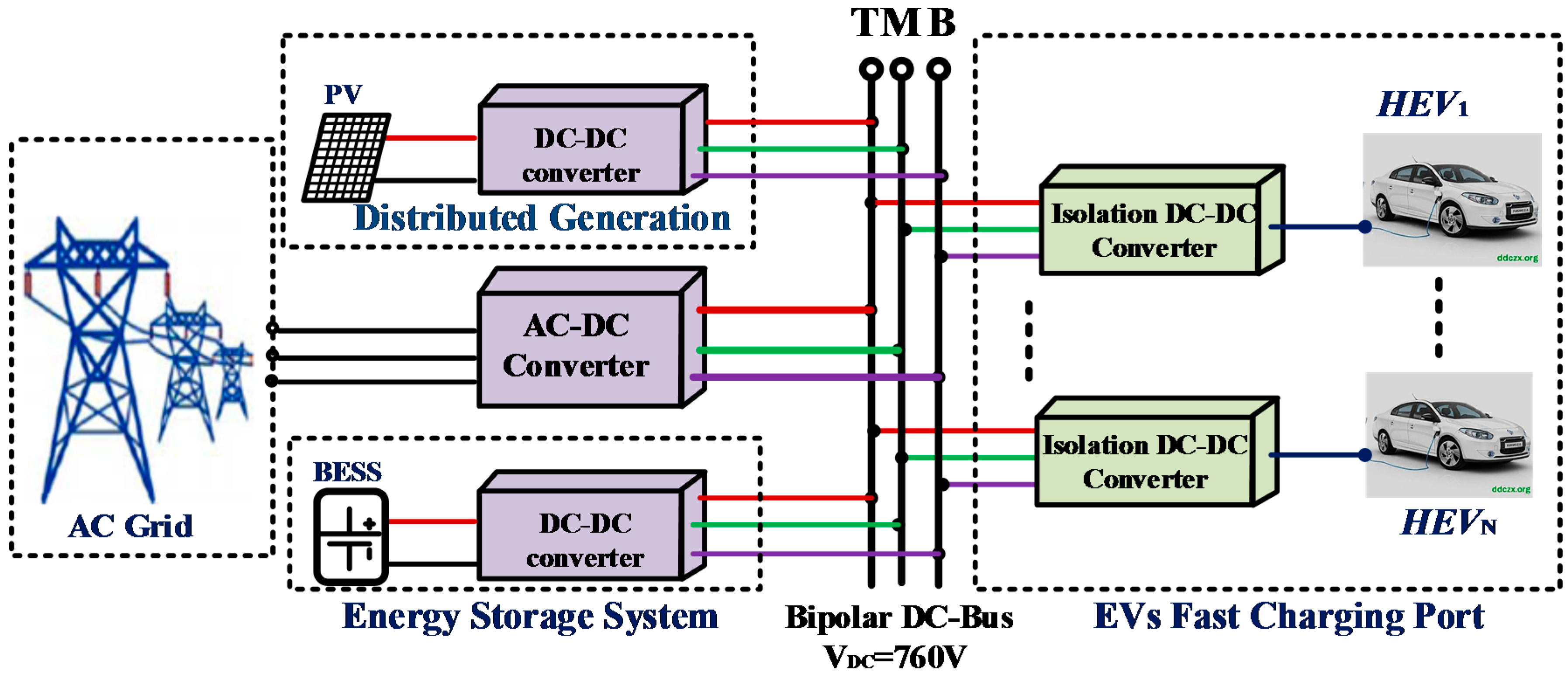
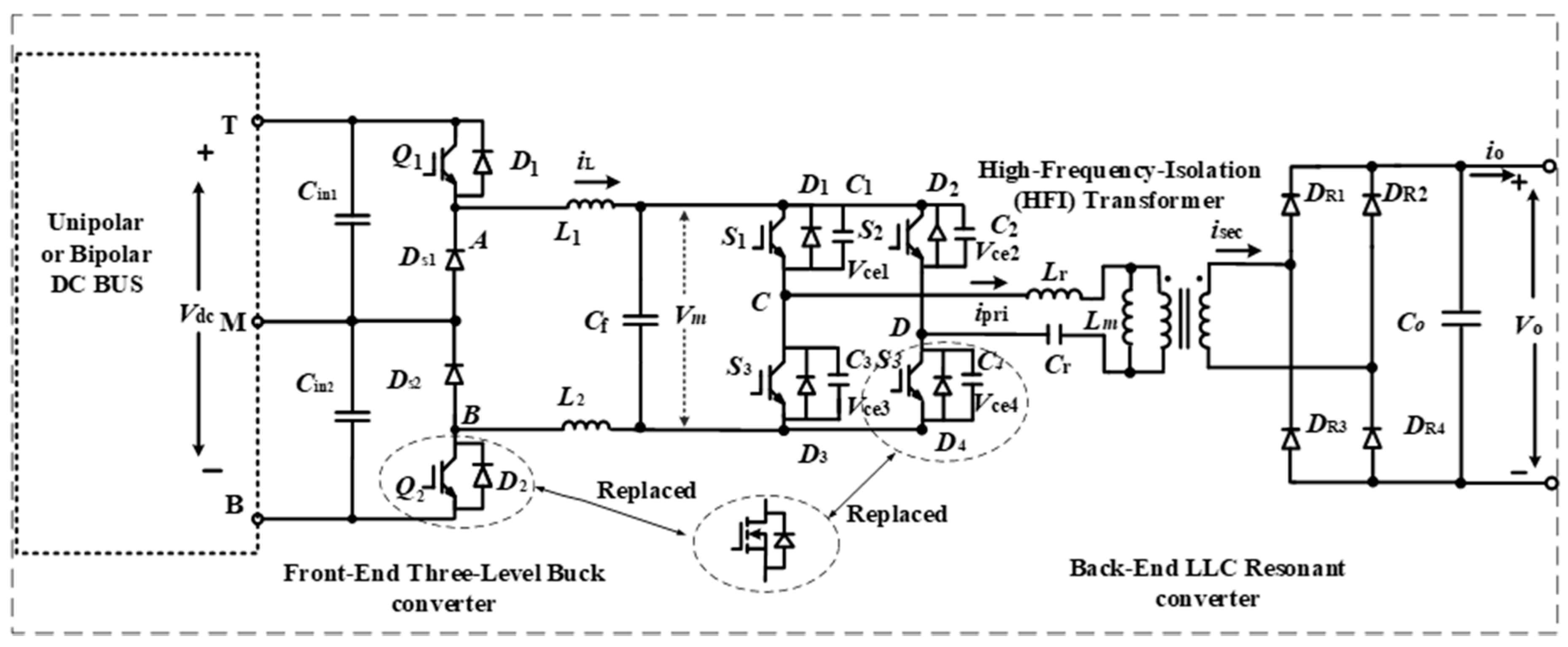
- According to the three-level converter, the low-voltage level rating power switches can be adapted/selected for the half-voltage stress of total DC bus. Additionally, the proposed system structure can be practical under high-voltage and high-power conditions.
- (2)
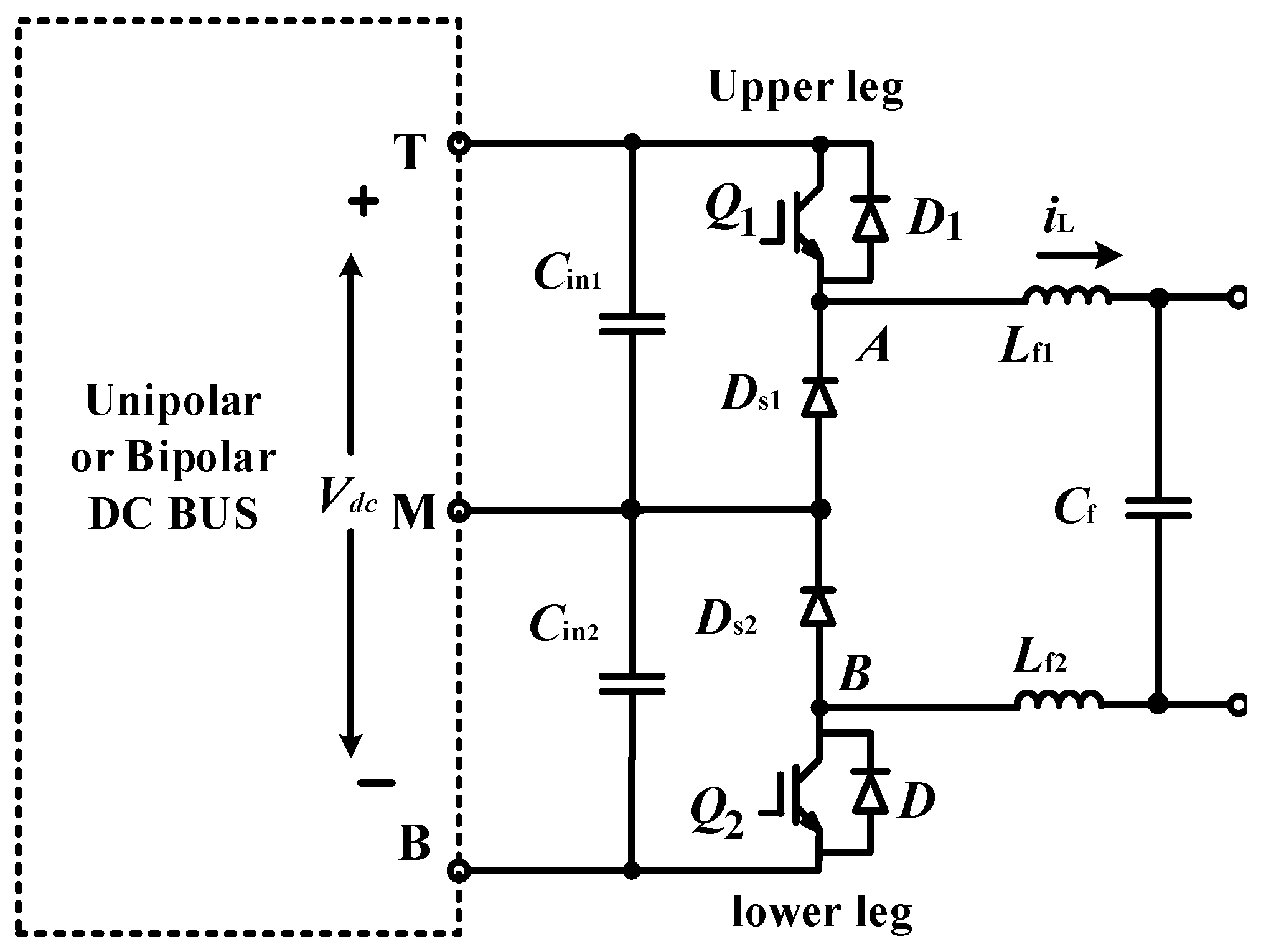
- The PWM phase-shift control for the front-end three-level buck converter can double the equivalent switching to greatly reduce the intermediate output LC filter volume.
- (3)
- The proposed structure can regulate the DC power balance without extra balancing circuits when the input terminals (T, M, B) are interfaced with the bipolar DC bus.
- (4)
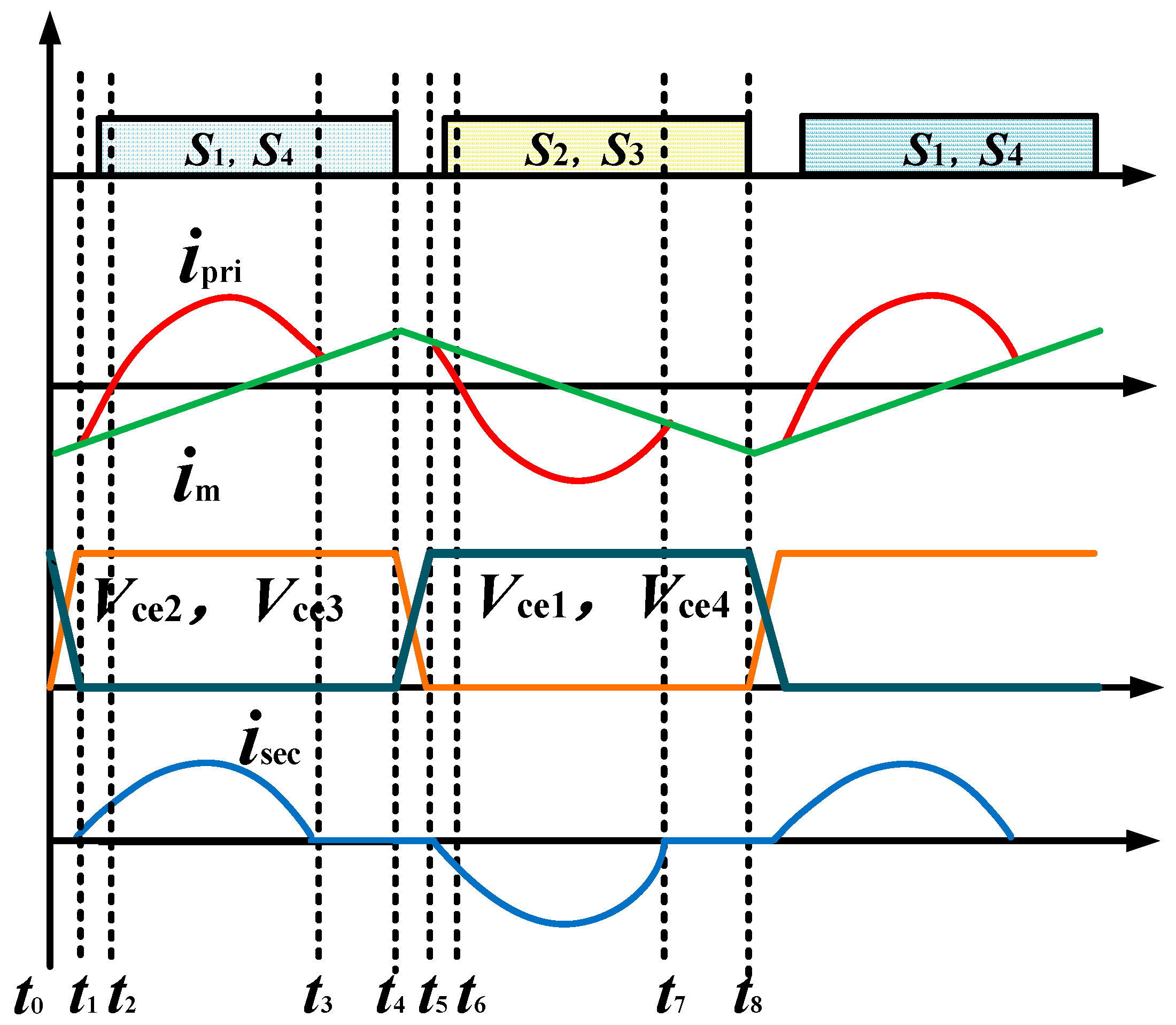
- The back-end LLC resonant converters have the advance characteristics of zero-voltage switching (ZVS) of the inverter side and zero-current switching (ZCS) of the rectifier side. In particular, it can achieve better performance under quasi-resonant frequency mode, which greatly decreases the loss of switches.
- (5)
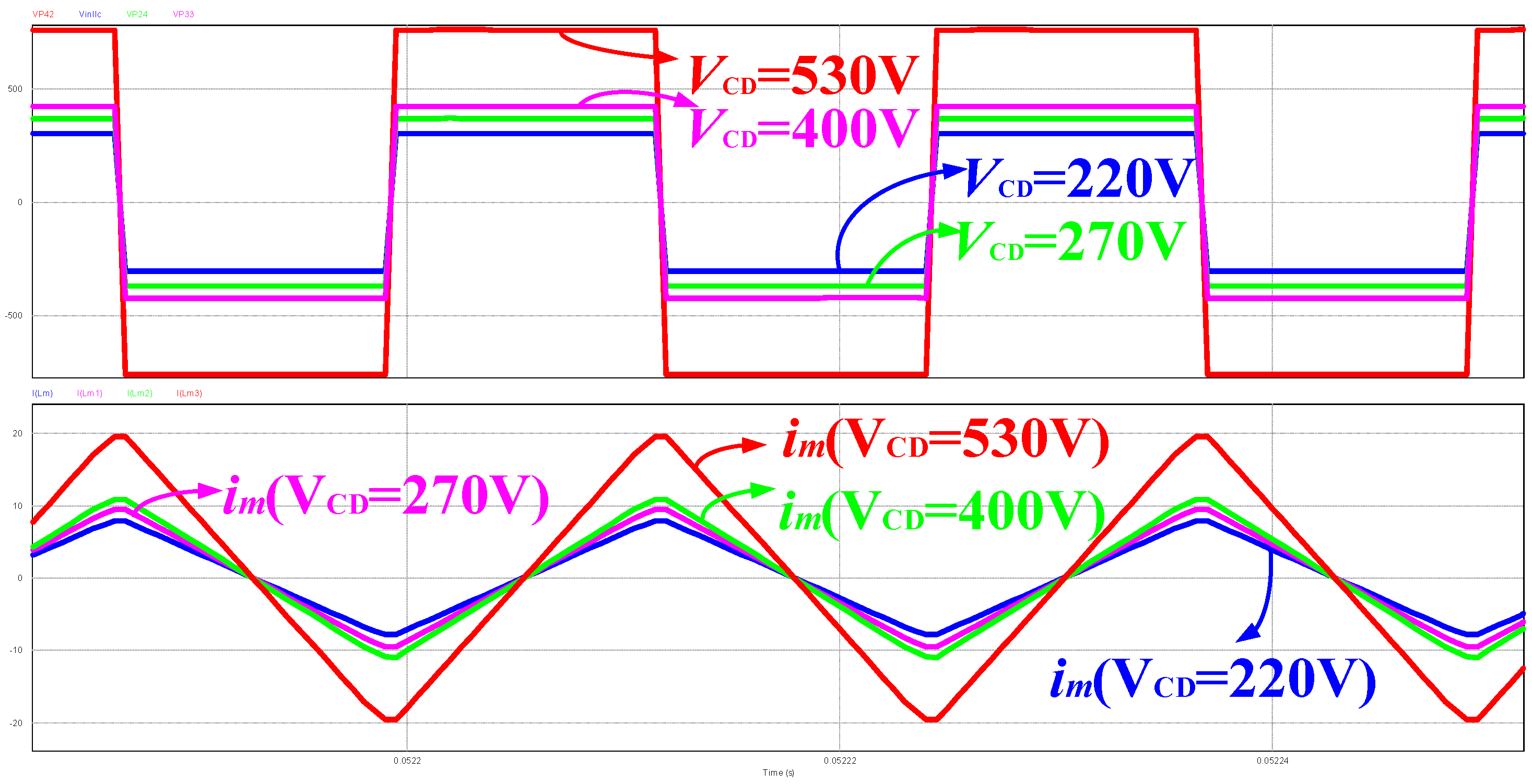
- The magnetizing current of LLC high-frequency transformer can be automatically modified by following the different DC output voltages, which have the self-adaption ZVS condition for decreasing the circulating current.
2.1. Front-End Three-Level Buck Converter
2.1.1. Operating Principle
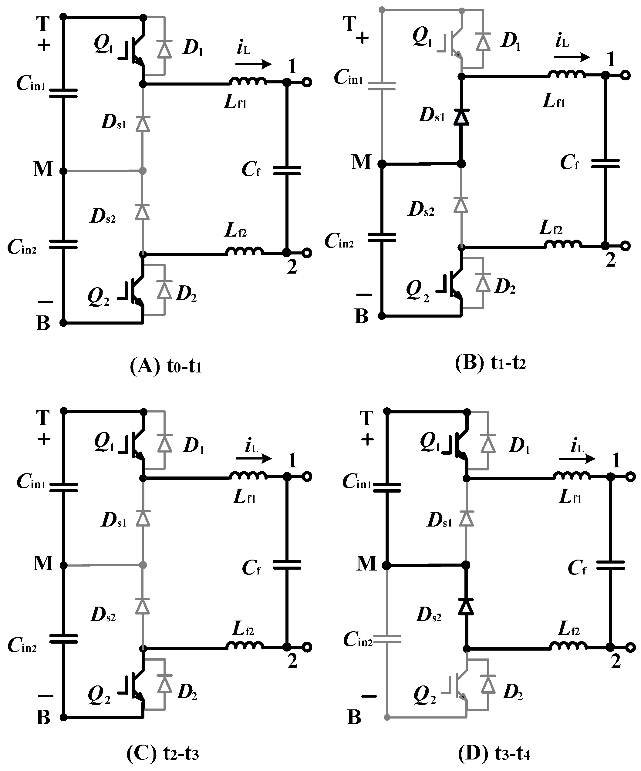
- Mode 1:
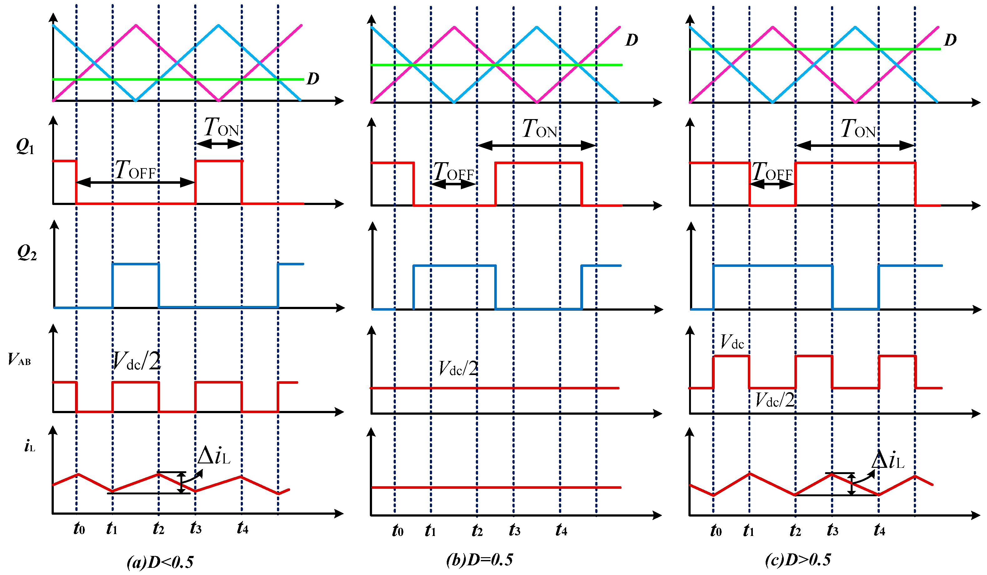
- When Q1 is turned on and Q2 is turned off, the generated voltage VAB is half of the DC side voltage 0.5 Vdc;
- Mode 2:
- When Q1 and Q2 are turned on at the same time, the generated voltage VAB is the total DC side voltage Vdc;
- Mode 3:
- When Q1 is tuned off and Q2 is turned on, the generated voltage VAB is half the DC side voltage 0.5 Vdc.
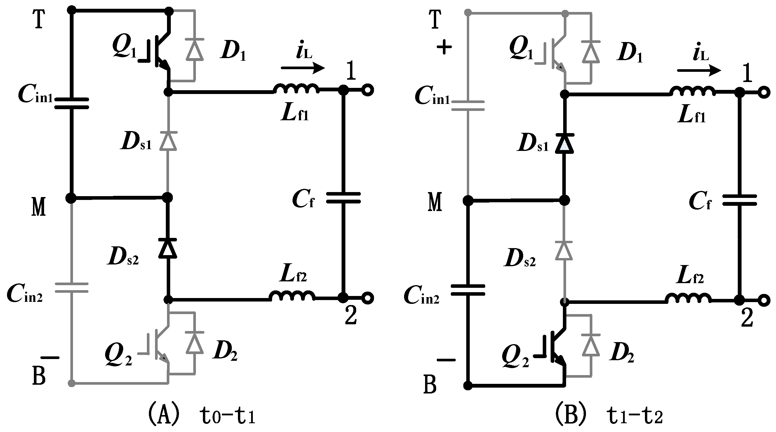
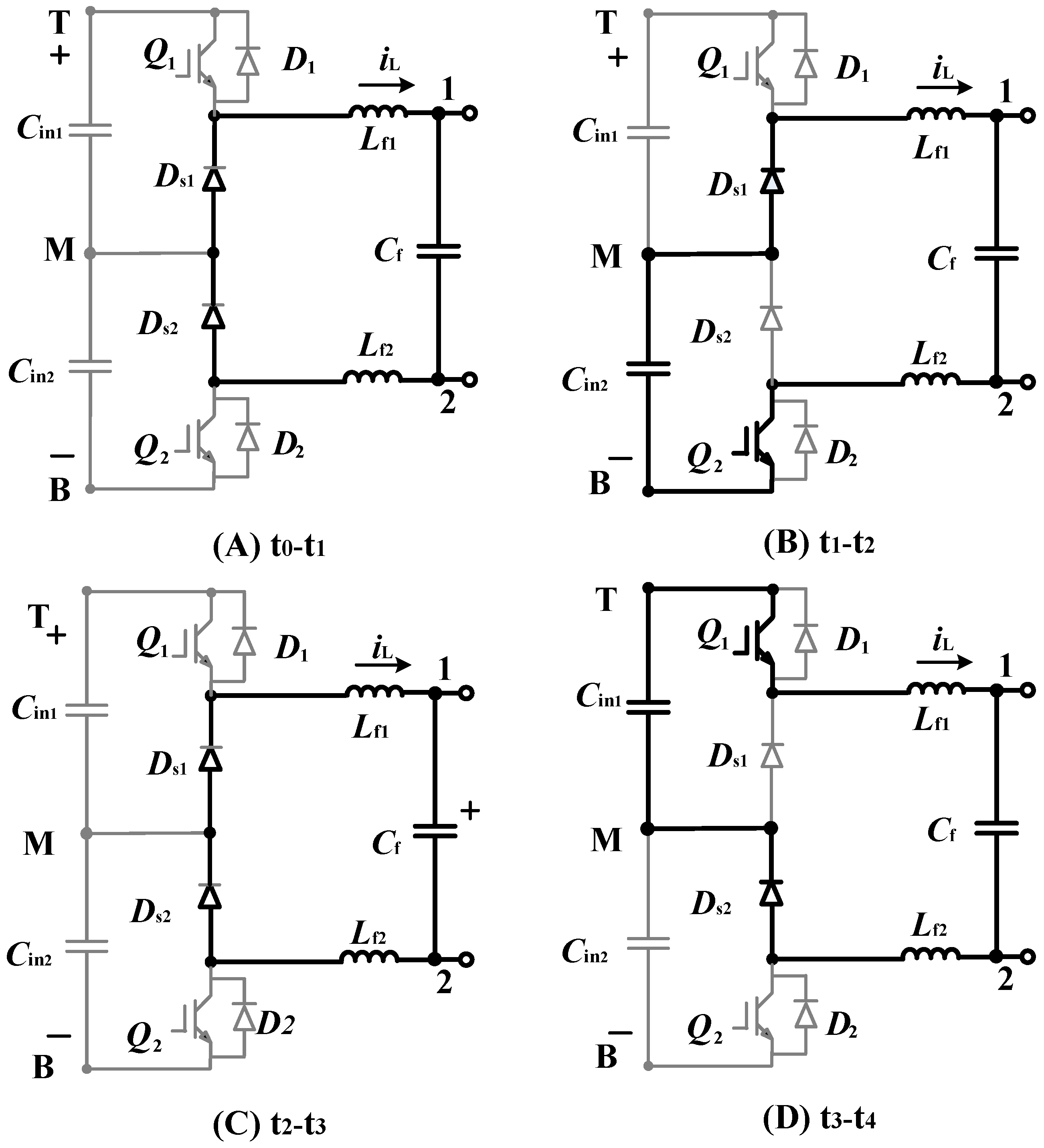
- Mode 1:
- When Q1 is turned off and Q2 is turned off at the same time, the generated voltage VAB is 0;
- Mode 2:
- When Q1 is turned off and Q2 is turned on, the generated voltage VAB is half of the DC side voltage 0.5 Vdc;
- Mode 3:
- When switch Q1 is turned on and Q2 is turned off, the generated voltage VAB is half of the DC side voltage 0.5 Vdc.
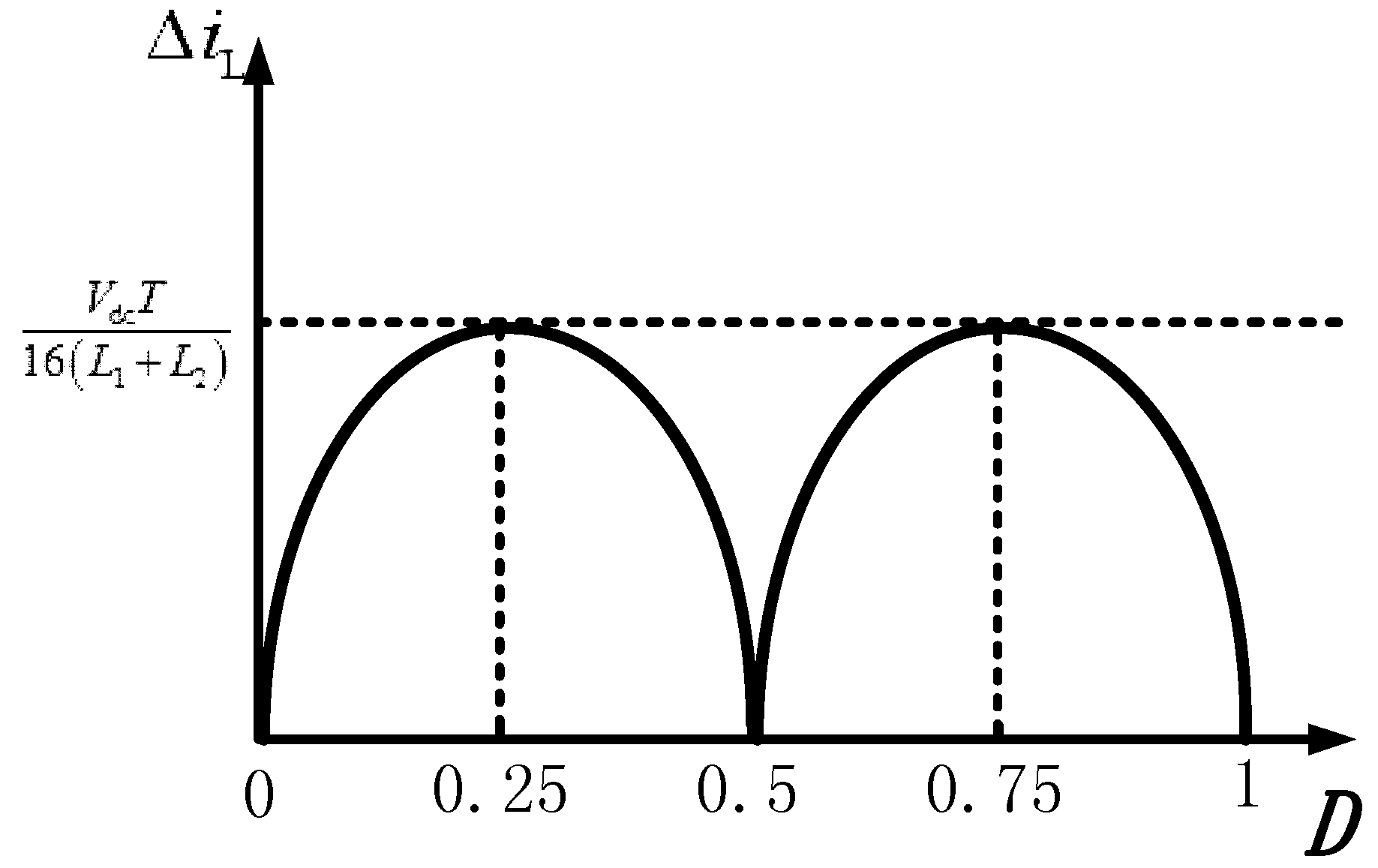
2.1.2. The Inductor Current Ripple Analysis
2.2. Back-End HFI LLC Resonant Converter
2.2.1. Operating Principle
2.2.2. Voltage Gain Characteristics of the LLC Resonant Converter
3. Features and Characteristics
3.1. Three-Level Buck Converter Working at Higher DC Modulation Index
3.2. The Proposed DC Charging Port Having Different Power Balancing Capability for a Bipolar DC Bus
3.3. LLC Resonant Converter Having ZVS Conditions with Different Magnetizing Current at Different Output Voltages
3.4. LLC Resonant Converter Containing Constant Current at Different Output Voltages with the Same Charging Current Command
4. Design Conditions
4.1. Front-End Three-Level Buck Converter Inductor Filter Design
4.2. Back-End LLC Converter ZVS Condition
4.3. High Frequency LLC Transformer Design
5. Experimental Results
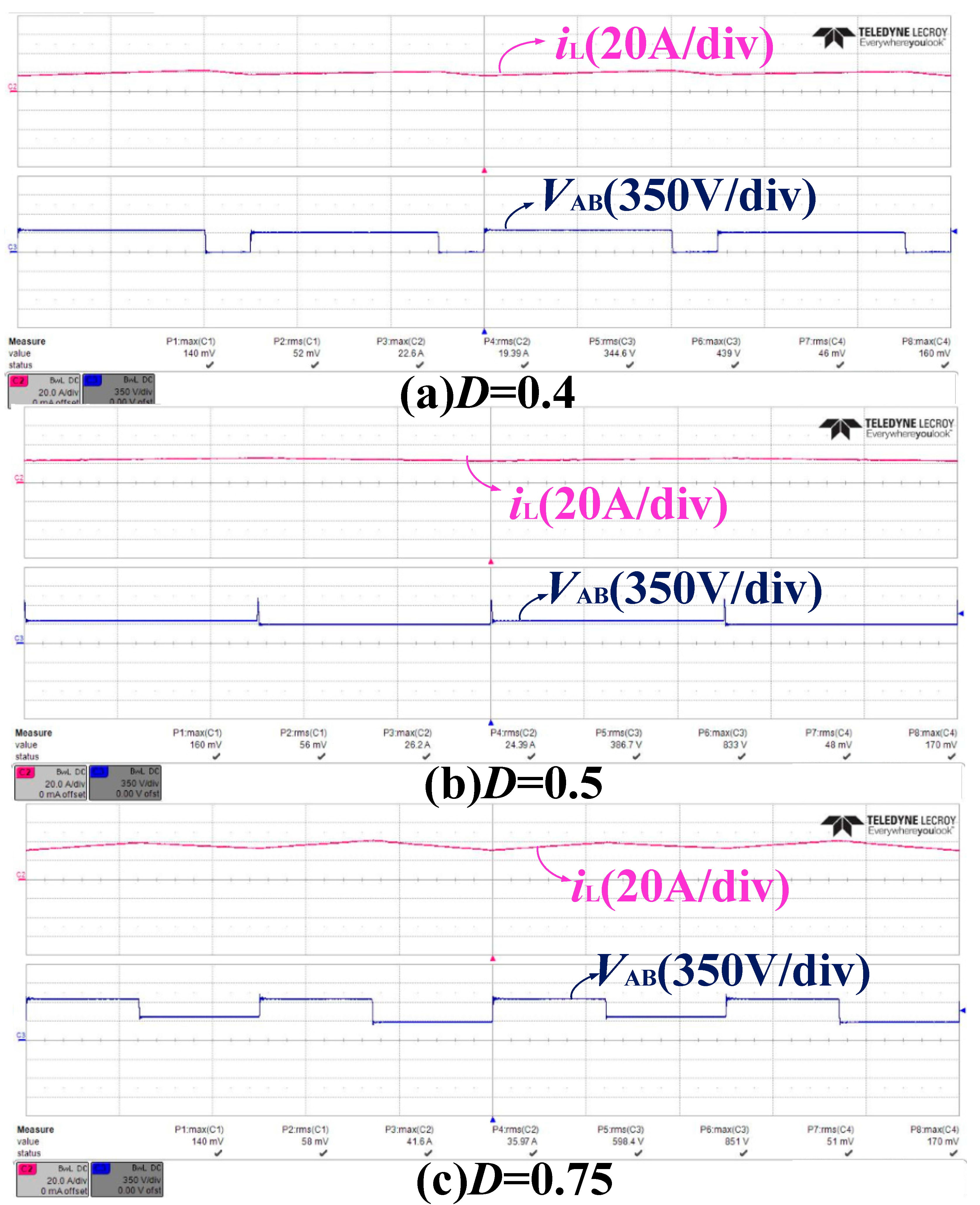
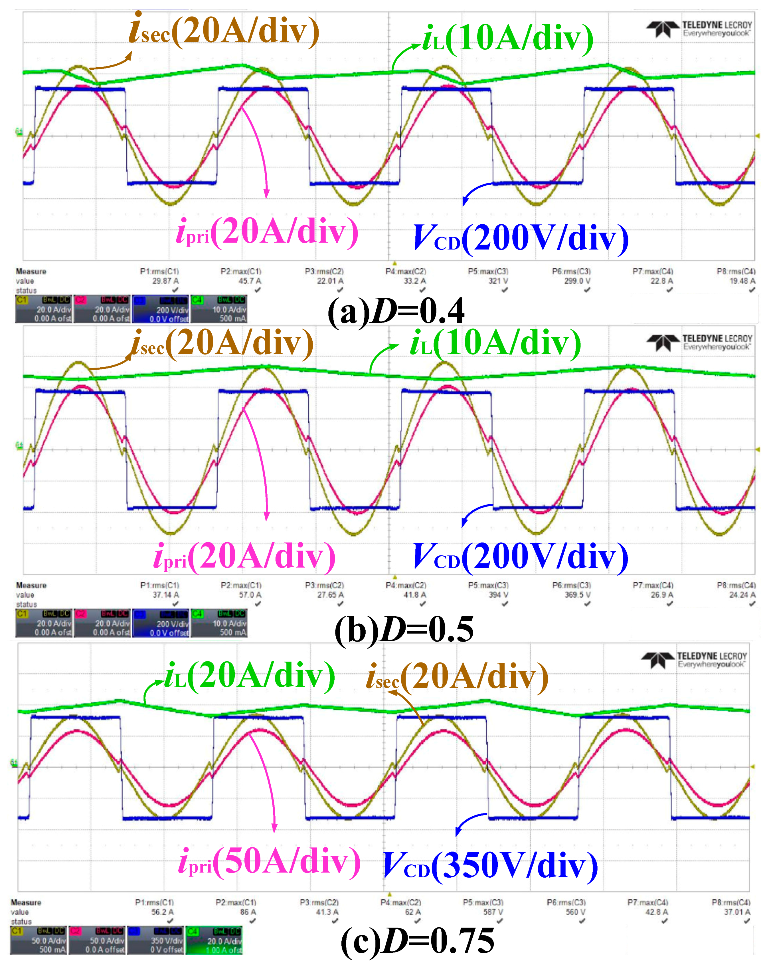
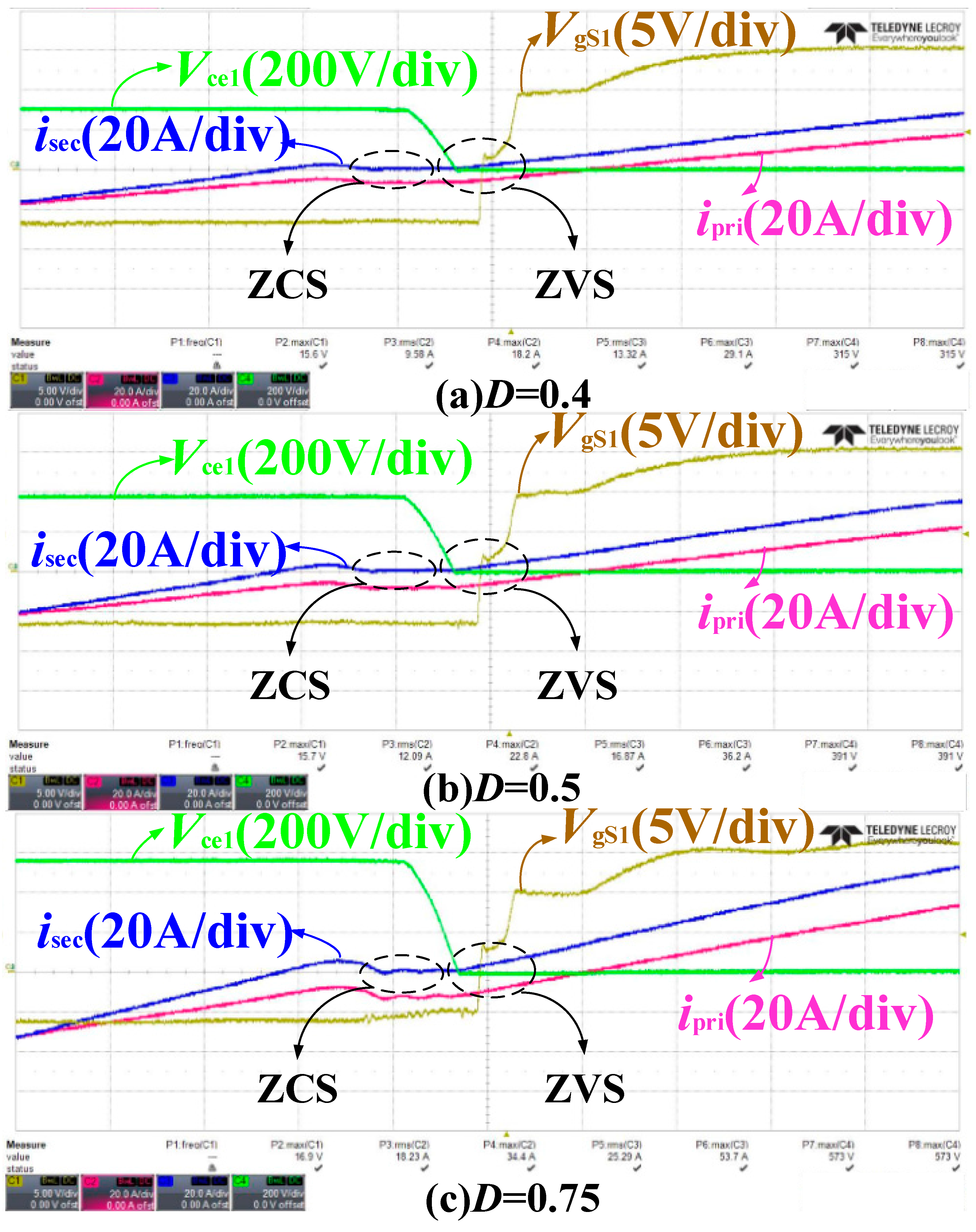
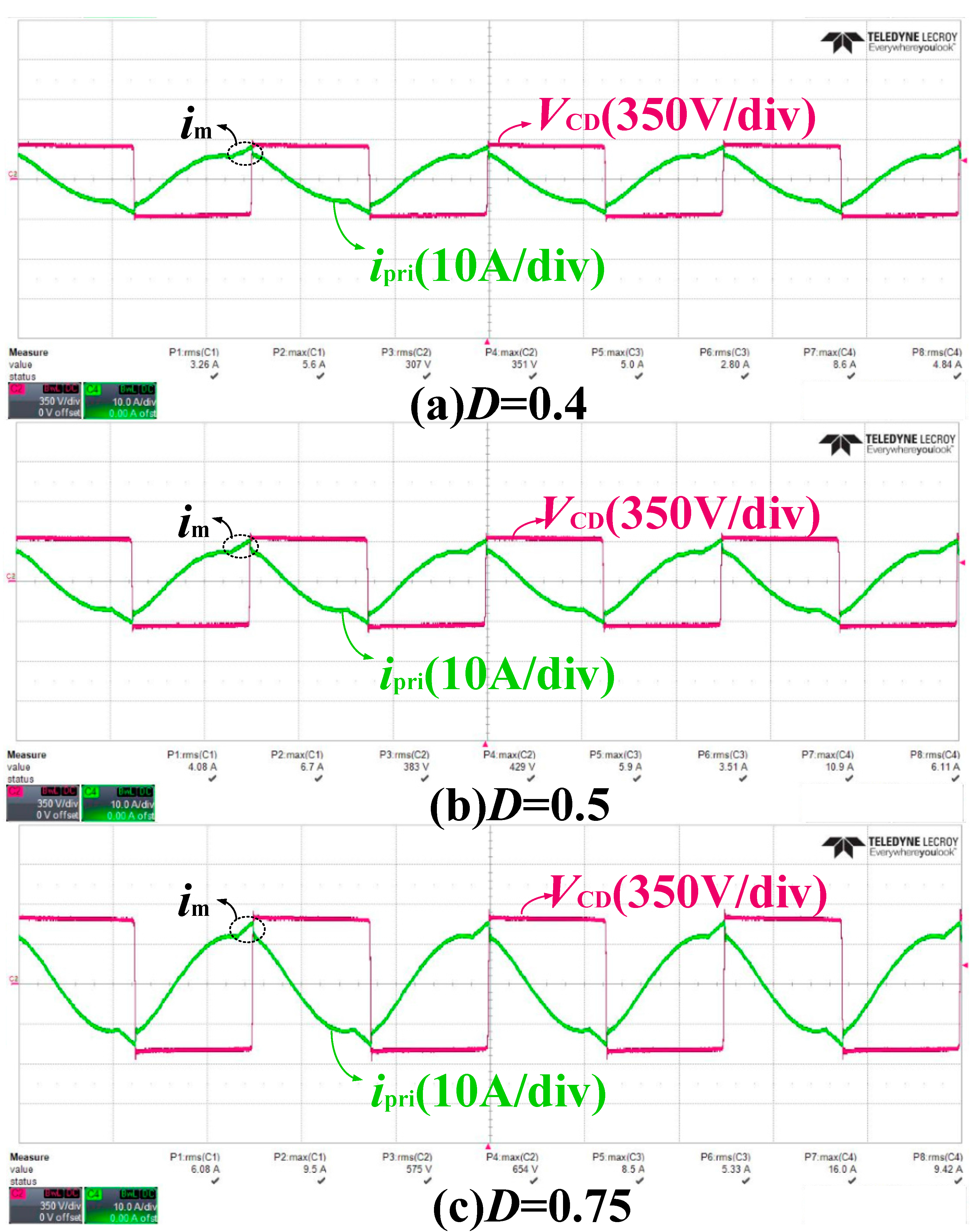
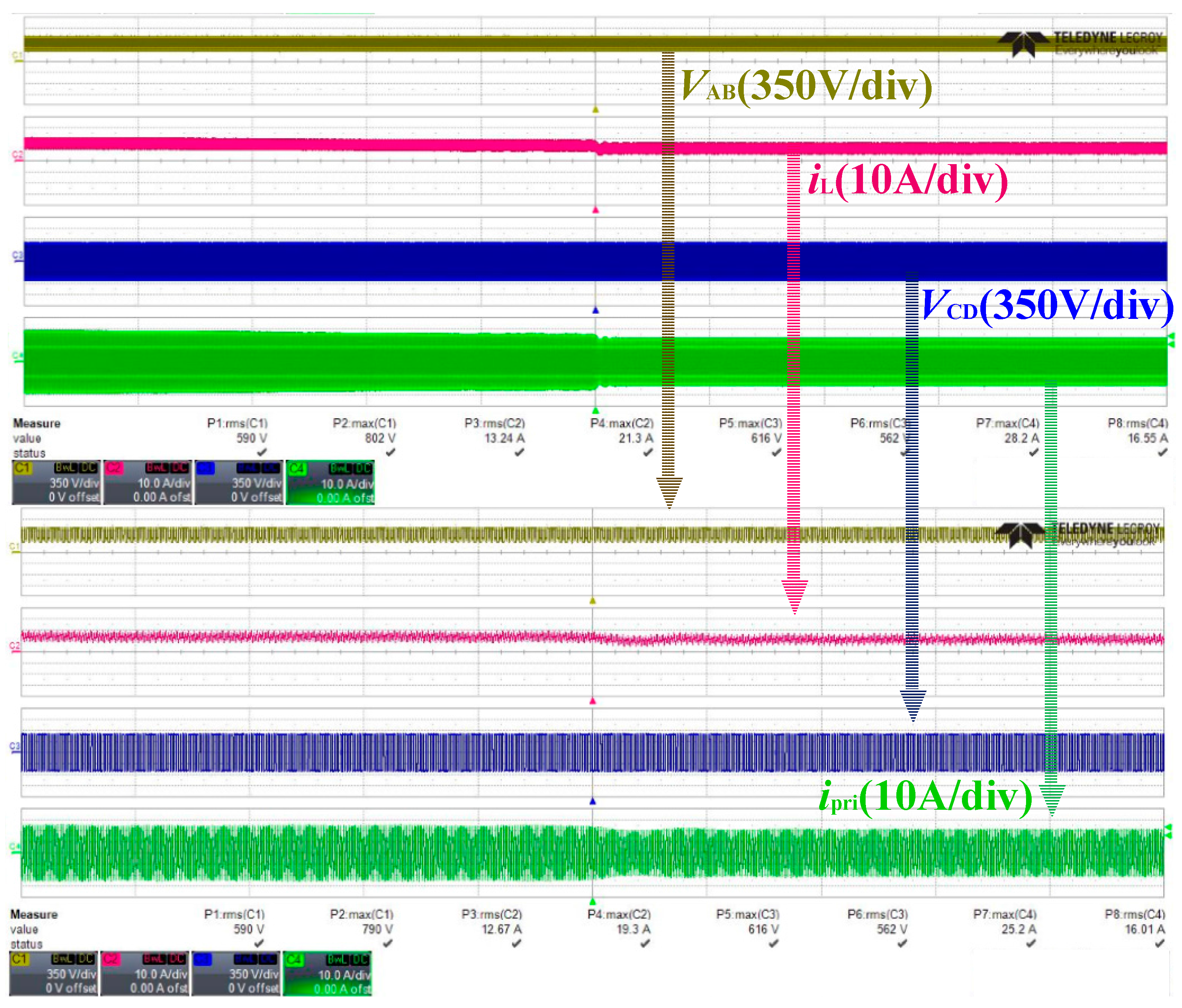
5.1. In Steady-State Operation
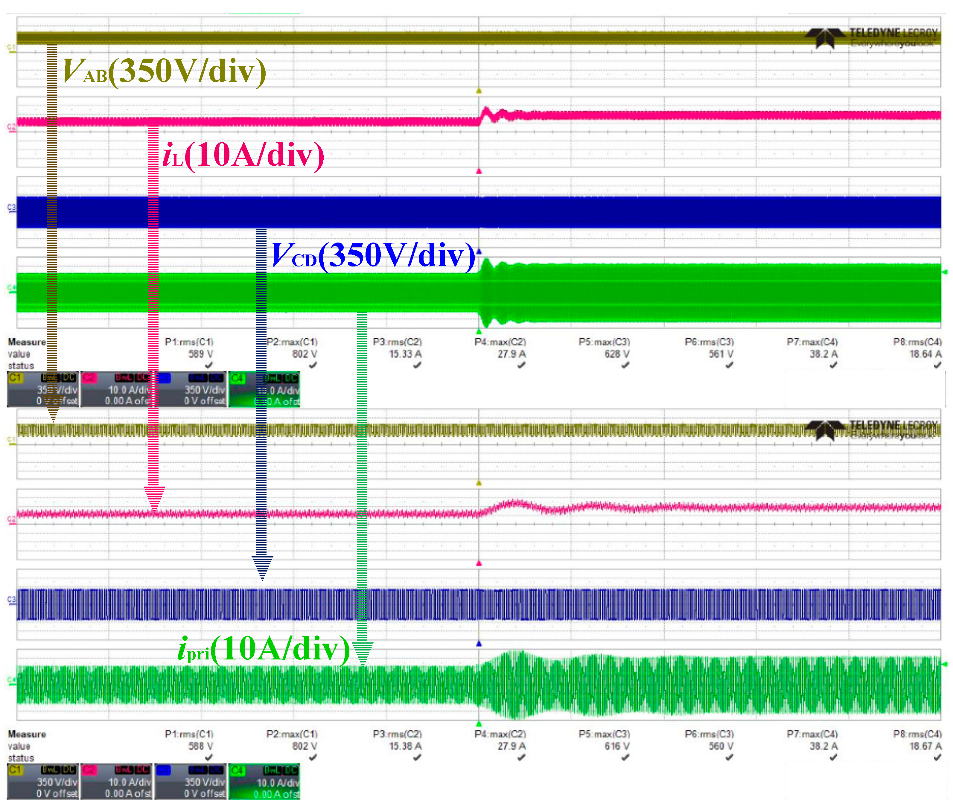
5.2. In the Load-Step Operation
6. Conclusions
Acknowledgments
Author Contributions
Conflicts of Interest
References
- Tabari, M.; Yazdani, A. An energy management strategy for a DC distribution system for power system integration of Plug-In Electric Vehicles. IEEE Trans. Smart Grid 2016, 7, 659–668. [Google Scholar] [CrossRef]
- Korolko, N.; Sahinoglu, Z.; Nikovski, D. Modeling and forecasting self-similar power load due to EV fast chargers. IEEE Trans. Smart Grid 2016, 7, 1620–1629. [Google Scholar] [CrossRef]
- Liu, C.; Gu, B.; Lai, J.S.; Wang, M.; Ji, Y.; Cai, G.; Zhao, Z.; Chen, C.L.; Zheng, C.; Sun, P. High-efficiency hybrid full-bridge–half-bridge converter with shared ZVS lagging leg and dual outputs in series. IEEE Trans. Power Electron. 2013, 28, 849–861. [Google Scholar] [CrossRef]
- Goli, P.; Shireen, W. PV integrated smart charging of PHEVs based on DC link voltage sensing. IEEE Trans. Smart Grid 2014, 5, 1421–1428. [Google Scholar] [CrossRef]
- Dubey, A.; Santoso, S.; Cloud, M.P. Average-value model of electric vehicle chargers. IEEE Trans. Smart Grid 2013, 4, 1549–1557. [Google Scholar] [CrossRef]
- Hredzak, B.; Agelidis, V.G.; Jang, M. A model predictive control system for a hybrid battery-ultracapacitor power source. IEEE Trans. Power Electron. 2014, 29, 1469–1479. [Google Scholar] [CrossRef]
- Channegowda, J.; Pathipati, V.K.; Williamson, S.S. Comprehensive review and comparison of DC fast charging converter topologies: Improving electric vehicle plug-to-wheels efficiency. In Proceedings of the 2015 IEEE 24th International Symposium on Industrial Electronics (ISIE 2015), Buzios, Brazil, 3–5 June 2015; pp. 263–268. [Google Scholar]
- Musavi, F.; Edington, M.; Eberle, W.; Dunford, W.G. Evaluation and efficiency comparison of front end AC-DC plug-in hybrid charger topologies. IEEE Trans. Smart Grid 2012, 3, 413–421. [Google Scholar] [CrossRef]
- Machiels, N.; Leemput, N.; Geth, F.; Van Roy, J.; Büscher, J.; Driesen, J. Design criteria for electric vehicle fast charge infrastructure based on flemish mobility behavior. IEEE Trans. Smart Grid 2014, 5, 320–327. [Google Scholar] [CrossRef]
- Bai, S.; Lukic, S.M. Unified active filter and energy storage system for an MW electric vehicle charging station. IEEE Trans. Power Electron. 2013, 28, 5793–5803. [Google Scholar] [CrossRef]
- Corchero, C.; Cruz-Zambrano, M.; Heredia, F.J. Optimal energy management for a residential microgrid including a vehicle-to-grid system. IEEE Trans. Smart Grid 2014, 5, 2163–2172. [Google Scholar]
- Atia, R.; Yamada, N. Sizing and analysis of renewable energy and battery systems in residential microgrids. IEEE Trans. Smart Grid 2016, 73, 1204–1213. [Google Scholar] [CrossRef]
- Lakshminarayana, S.; Xu, Y.; Poor, H.V.; Quek, T.Q. Cooperation of storage operation in a power network with renewable generation. IEEE Trans. Smart Grid 2016, 7, 2108–2122. [Google Scholar] [CrossRef]
- Oliveira, T.R.; Silva, W.W.A.G.; Donoso-Garcia, P.F. Distributed secondary level control for energy storage management in dc microgrids. IEEE Trans. Smart Grid 2016, 1–11. [Google Scholar] [CrossRef]
- Falcones, S.; Ayyanar, R.; Mao, X. A DC–DC multiport-converter-based solid-state transformer integrating distributed generation and storage. IEEE Trans. Power Electron. 2013, 28, 2192–2203. [Google Scholar] [CrossRef]
- Shin, C.J.; Lee, J.Y. An electrolytic capacitor-less bi-directional EV on-board charger using harmonic modulation technique. IEEE Trans. Power Electron. 2014, 29, 5195–5203. [Google Scholar] [CrossRef]
- Rivera, S.; Wu, B.; Kouro, S.; Yaramasu, V.; Wang, J. Electric vehicle charging station using a neutral point clamped converter with bipolar DC bus. IEEE Trans. Ind. Electron. 2015, 62, 1999–2009. [Google Scholar] [CrossRef]
- Liu, C.; Sun, P.; Lai, J.S.; Ji, Y.; Wang, M.; Chen, C.L.; Cai, G. Cascade dual-boost/buck active-front-end converter for intelligent universal transformer. IEEE Trans. Ind. Electron. 2012, 59, 4671–4680. [Google Scholar]
- Tan, L.; Wu, B.; Rivera, S.; Yaramasu, V. Comprehensive DC power balance management in high-power three-level DC–DC converter for electric vehicle fast charging. IEEE Trans. Power Electron. 2016, 31, 89–100. [Google Scholar] [CrossRef]
- SAE Electric Vehicle and Plug-in Hybrid Electric Vehicle Conductive Charge Coupler; J1772; SAE International: Warrendale, PA, USA, 2010.
- Yilmaz, M.; Krein, P.T. Review of battery charger topologies, charging power levels, and infrastructure for plug-in electric and hybrid vehicles. IEEE Trans. Power Electron. 2013, 28, 2151–2169. [Google Scholar] [CrossRef]
- Vasiladiotis, M.; Rufer, A. A modular multiport power electronic transformer with integrated split battery energy storage for versatile ultrafast EV charging stations. IEEE Trans. Ind. Electron. 2015, 62, 3213–3222. [Google Scholar] [CrossRef]
- Dusmez, S.; Khaligh, A. A compact and integrated multifunctional power electronic interface for plug-in electric vehicles. IEEE Trans. Power Electron. 2013, 28, 5690–5701. [Google Scholar] [CrossRef]
- Lu, X.; Iyer, K.L.V.; Mukherjee, K.; Kar, N.C. A dual purpose triangular neural network based module for monitoring and protection in Bi-directional off-board level-3 charging of EV/PHEV. IEEE Trans. Smart Grid 2012, 3, 1670–1678. [Google Scholar] [CrossRef]
- Wang, Z.; Li, H. An integrated three-port bidirectional DC–DC converter for PV application on a DC distribution system. IEEE Trans. Power Electron. 2013, 28, 4612–4624. [Google Scholar] [CrossRef]
- Kim, S.Y.; Song, H.S.; Nam, K. Idling port isolation control of three-port bidirectional converter for EVs. IEEE Trans. Power Electron. 2012, 27, 2495–2506. [Google Scholar] [CrossRef]
- Kim, S.; Kang, F.S. Multifunctional onboard battery charger for plug-in electric vehicles. IEEE Trans. Ind. Electron. 2015, 62, 3460–3472. [Google Scholar]
- Subotic, I.; Bodo, N.; Levi, E.; Jones, M.; Levi, V. Isolated chargers for EVs incorporating six-phase machines. IEEE Trans. Ind. Electron. 2016, 63, 653–664. [Google Scholar] [CrossRef]
- Everts, J.; Krismer, F.; Van Den Keybus, J.; Driesen, J.; Kolar, J.W. Optimal ZVS modulation of single-phase single-stage bidirectional DAB AC–DC converters. IEEE Trans. Power Electron. 2014, 29, 3954–3970. [Google Scholar] [CrossRef]
- Gu, B.; Lai, J.S.; Kees, N.; Zheng, C. Hybrid-switching full-bridge DC–DC converter with minimal voltage stress of bridge rectifier, reduced circulating losses, and filter requirement for electric vehicle battery chargers. IEEE Trans. Power Electron. 2013, 28, 1132–1144. [Google Scholar] [CrossRef]
- Tan, X.; Ruan, X. Equivalence relations of resonant tanks: A new perspective for selection and design of resonant converters. IEEE Trans. Ind. Electron. 2016, 63, 2111–2123. [Google Scholar] [CrossRef]
- Kheraluwala, M.N.; Gascoigne, R.W.; Divan, D.M.; Baumann, E.D. Performance characterization of a high-power dual active bridge DC-to-DC converter. IEEE Trans. Ind. Appl. 1992, 28, 1294–1301. [Google Scholar] [CrossRef]
- Haihua, Z.; Khambadkone, A.M. Hybrid modulation for dual active bridge bi-directional converter with extended power range for ultra-capacitor application. In Proceedings of the IEEE Industry Applications Society Annual Meeting, Edmonton, AB, Canada, 5–9 October 2008; pp. 1–8. [Google Scholar]
- Pinheiro, J.R.; Barbi, I. The three-level ZVS PWM converter-a new concept in high voltage DC-to-DC conversion. In Proceedings of the 1992 International Conference on Industrial Electronics, Control, Instrumentation, and Automation, San Diego, CA, USA, 13 November 1992; pp. 173–178. [Google Scholar]
- Ruan, X.; Li, B.; Chen, Q. Three-level converters—A new approach for high voltage and high power DC-to-DC conversion. In Proceedings of the 2002 IEEE 33rd Annual IEEE Power Electronics Specialists Conference, Cairns, Queensland, Australia, 23–27 June 2002; Volume 2, pp. 663–668. [Google Scholar]
- Steigerwald, R.L. A comparison of half-bridge resonant converter topologies. IEEE Trans. Power Electron. 1988, 3, 174–182. [Google Scholar] [CrossRef]
- Kundu, U.; Yenduri, K.; Sensarma, P. Accurate ZVS Analysis for Magnetic Design and Efficiency Improvement of Full-Bridge LLC Resonant Converter. IEEE Trans. Power Electron. 2017, 32, 1703–1706. [Google Scholar] [CrossRef]
- Hurley, W.G.; Wolfle, W.H. Transformers and Inductors for Power Electronics: Theory, Design and Applications; China Machine Press: Beijing, China, 2014; pp. 46–47. [Google Scholar]


| Charger Location | Level 1 | Level 2 | Level 3 | |
|---|---|---|---|---|
| On-board chargers | Vac | 120 V | 240 V | - |
| Iac | 12 A | 80 A | - | |
| Plevel | 1.4 kW | <19.2 kW | >20 kW | |
| Off-board chargers | Vdc (V) | Vdc ≤ 450 | Vdc ≤ 450 | Vdc ≤ 600 |
| Idc (A) | Idc ≤ 80 | Idc ≤ 200 | Idc ≤ 400 | |
| Plevel (kW) | Plevel ≤ 36 | Plevel ≤ 90 | Plevel ≤ 240 | |
| Description | Parameters |
|---|---|
| Input voltage Vdc | 760 V (DC) |
| Output voltage Vo | 200–500 V (DC) |
| Transformer turn ratio n | 17:12 |
| Three-level buck converter working frequency f | 20 kHz |
| LLC resonant converter working frequency fs | 40 kHz |
| Resonant frequency fr | 44 kHz |
© 2017 by the authors. Licensee MDPI, Basel, Switzerland. This article is an open access article distributed under the terms and conditions of the Creative Commons Attribution (CC BY) license (http://creativecommons.org/licenses/by/4.0/).
Share and Cite
Cai, G.; Liu, D.; Liu, C.; Li, W.; Sun, J. A High-Frequency Isolation (HFI) Charging DC Port Combining a Front-End Three-Level Converter with a Back-End LLC Resonant Converter. Energies 2017, 10, 1462. https://doi.org/10.3390/en10101462
Cai G, Liu D, Liu C, Li W, Sun J. A High-Frequency Isolation (HFI) Charging DC Port Combining a Front-End Three-Level Converter with a Back-End LLC Resonant Converter. Energies. 2017; 10(10):1462. https://doi.org/10.3390/en10101462
Chicago/Turabian StyleCai, Guowei, Duolun Liu, Chuang Liu, Wei Li, and Jiajun Sun. 2017. "A High-Frequency Isolation (HFI) Charging DC Port Combining a Front-End Three-Level Converter with a Back-End LLC Resonant Converter" Energies 10, no. 10: 1462. https://doi.org/10.3390/en10101462
APA StyleCai, G., Liu, D., Liu, C., Li, W., & Sun, J. (2017). A High-Frequency Isolation (HFI) Charging DC Port Combining a Front-End Three-Level Converter with a Back-End LLC Resonant Converter. Energies, 10(10), 1462. https://doi.org/10.3390/en10101462


