Advanced Reactive Power Reserve Management Scheme to Enhance LVRT Capability

1
School of Electrical Engineering, Korea University, Anam Campus, 145 Anam-ro, Seongbuk-gu, Seoul 02841, Korea
2
Korea Electric Power Research Institute (KEPRI), Korea Electric Power Corporation (KEPCO), 105 Munji-Ro, Yuseong-Gu, Deajeon 305-760, Korea
*
Author to whom correspondence should be addressed.
Energies 2017, 10(10), 1540; https://doi.org/10.3390/en10101540
Submission received: 7 September 2017
/
Revised: 27 September 2017
/
Accepted: 27 September 2017
/
Published: 5 October 2017
(This article belongs to the Special Issue Wind Generators Modelling and Control)
Abstract
:To increase the utilization of wind power in the power system, grid integration standards have been proposed for the stable integration of large-scale wind power plants. In particular, fault-ride-through capability, especially Low-Voltage-Ride-Through (LVRT), has been emphasized, as it is related to tripping in wind farms. Therefore, this paper proposes the Wind power plant applicable-Effective Reactive power Reserve (Wa-ERPR), which combines both wind power plants and conventional generators at the Point of Interconnection (POI). The reactive power capability of the doubly-fed induction generator wind farm was considered to compute the total Wa-ERPR at the POI with reactive power capability of existing generators. By using the Wa-ERPR management algorithm, in case of a violation of the LVRT standards, the amount of reactive power compensation is computed using the Wa-ERPR management scheme. The proposed scheme calculates the Wa-ERPR and computes the required reactive power, reflecting the change of the system topology pre- and post-contingency, to satisfy the LVRT criterion when LVRT regulation is not satisfied at the POI. The static synchronous compensator (STATCOM) with the capacity corresponding to calculated amount of reactive power through the Wa-ERPR management scheme is applied to the POI. Therefore, it is confirmed that the wind power plant satisfies the LVRT criteria by securing the appropriate reactive power at the POI, by applying of the proposed algorithm.
1. Introduction
Lately, interest in renewable energy has been gradually increasing because of the depletion of fossil fuels, and the limitations placed on greenhouse gas emissions. The Korean government plans to install 53 GW of new renewable capacity by 2030. Of this 53 GW, wind and photovoltaic power generation will account for approximately 80%. It is easier to construct large plants for wind power generation than for solar power generation; therefore, wind power generation will be directly connected to the transmission systems as well as distribution system. As the utilization of new and renewable energy is being accelerated by the support of governmental policies and the construction of large-scale renewable energy plants, the stability of the power grid including the existing synchronous generators becomes an important issue; thus, the technical requirements for a wind power farm become stricter.
As the impact on the stability of the power system increases due to the connection of large quantities of renewable power, the technical requirements for wind power plants have also been made stricter [1]. In addition, the development of power electronics technologies related to converters facilitates the controllability of generators such as the Doubly-Fed Induction Generator (DFIG), which is connected to a grid via a converter. The grid code states that a large-scale wind farm should have a variable control ability, which is the case with the existing generators. Among the various grid codes, it is the Low-Voltage-Ride-Through (LVRT) criterion that explains the operational aspects of wind turbine connection. The LVRT condition refers to the ability of a Wind Power Plant (WPP) to remain connected to a grid in a short-term transient situation, when certain events occur in the grid.
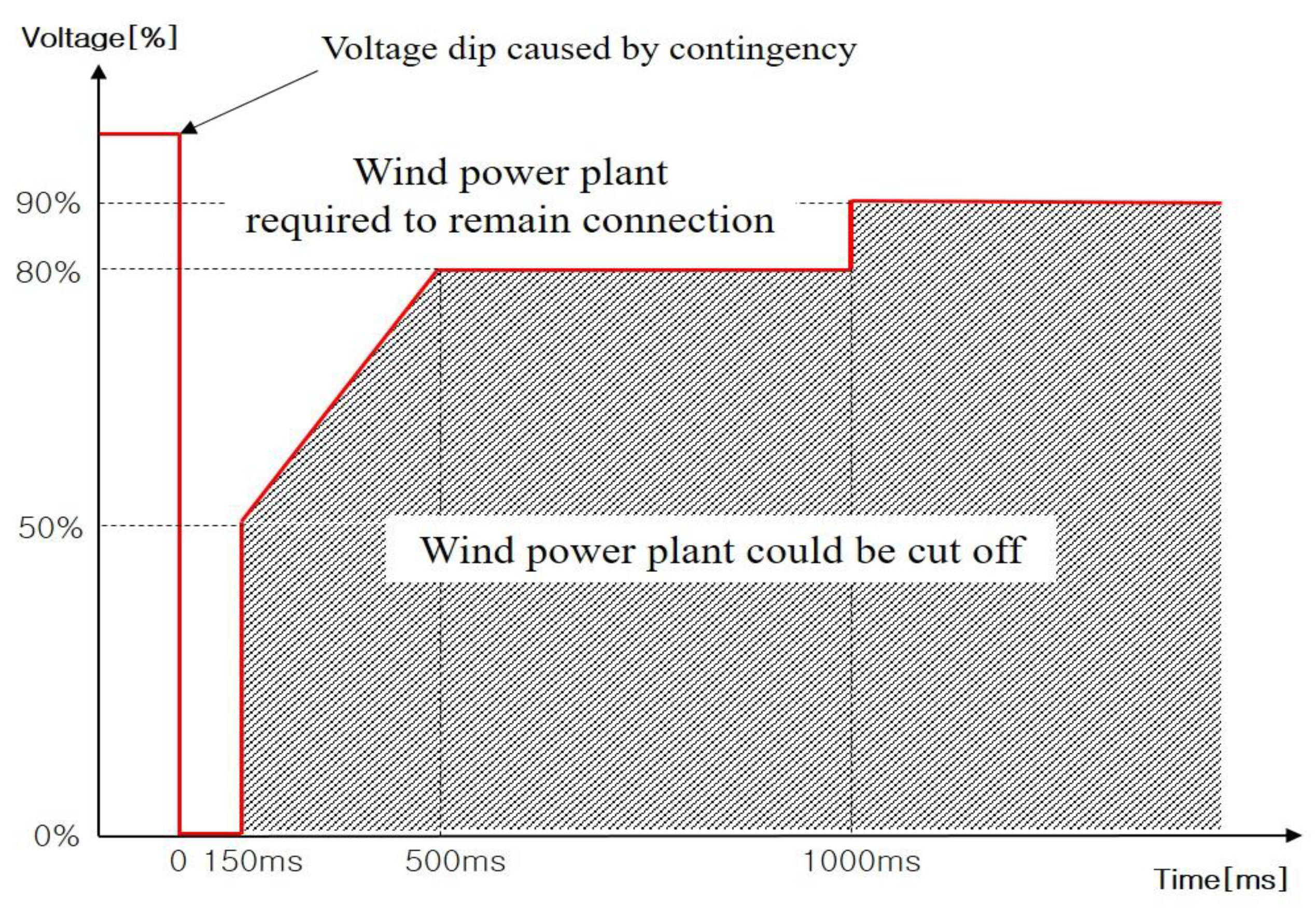
The LVRT code in the Korean grid code is shown in Figure 1. It states that a wind turbine should stay connected to the grid if the after-fault voltage is above the LVRT curve. However, it is permitted to disconnect from the grid when the voltage drops below the curve. In general, this criterion is applied to the high voltage side at the Point of Interconnection (POI) of the wind farm and the grid. It is divided into two parts. The first part is the “fault period.” If the fault is not cleared, the POI voltage of the wind power farm drops to approximately zero. Accordingly, the DFIG wind power generation with control capability undertakes voltage control to satisfy the LVRT code. Therefore, in this part, not only is the voltage control of wind farms and important concern, but also is the clearing fault time. The second part is the “dynamic voltage recovery.” After fault clearing, the voltage of the wind farms increases. A variety of adjustment methods can be used to aid in increasing the voltage to normal levels by feeding a mass of reactive power (Q) into the network. Thus, if the q is insufficient, disconnection of the wind farm will still occur, because the voltage at the POI fails to recovery promptly [2].
Traditionally, in the case of a Type-3 or Type-4 wind turbine, the LVRT condition is satisfied by converter control, because the converter can control the reactive power. However, a wind farm comprises a number of individual wind turbines integrated at a POI, whereas traditional generator control is for only one generator and one POI. Therefore, to satisfy the LVRT conditions, the control of a wind farm should be centralized, rather than having individual control of each generator [3].
Recent studies on the LVRT code have mainly focused on the control of wind generators or farms [4]. Gounder [5] used STATCOM to secure the transient stability of a distribution system where a Squirrel Cage Induction Generator (SCIG) and DFIG are connected, which inherently lack control capability. Duong [6] proposed an analysis model for the transient stability of the SCIG, and applied the proposed control algorithm to verify its conformance to Fault-Ride-Through (FRT) standard. As the use of DFIGs and Permanent Magnet Synchronous Generators (PMSGs) increases, which are connected to a grid via converters, more studies focus on the voltage-reactive power control of the wind power source itself. Zhong [7] attempted to apply the coordinate control scheme of active and reactive power to the Grid-Side Converter (GSC). Shen [8] proposed an algorithm that made the GSC, as well as the Rotor-Side Converter (RSC) participate in the reactive power control, according to the level of voltage sag. Kim [9] calculated the reactive power capability of a wind farm, and verified the wake effect of the wind farm through the application of an adaptive voltage controller. Qiao and Hasan [10,11] conducted a study on a method of satisfying LVRT standards by means of voltage control of a DFIG wind farm and STATCOM. Camm and Patel [12,13] explained the characteristics of reactive power compensation equipment and described that it can be used as a source of reactive power to satisfy the LVRT standard. Nguyen [14] illustrated that STATCOM can be participate in voltage control by supplying additional reactive power when controlled in conjunction with a PMSG wind farm. Zheng [15] proposed a coordinated control scheme that meets LVRT criteria by using DFIG based wind farm and STATCOM under asymmetrical grid fault situation. However, these studies solely focused on the control system of a wind generator and farm, and grid topology and conditions were not considered. The reactive power, in terms of the grid, was examined in [16,17]. Choi [18] defined the Reactive Power Reserve (RPR) from the perspective of voltage stability analysis. Seo [19] focused on hierarchical voltage control for controlling the regional voltage profile and thus, could not construct a reactive power management scheme that meets the LVRT criterion at the POI where a wind farm is connected to a grid.
Therefore, in this paper, an RPR management scheme at the POI, to enhance the LVRT capability of a large-scale wind power farm, is proposed. In order to estimate the influence of the reactive power of generators on POI, a Jacobian matrix based on system data against pre- and post-contingency situations is computed. A weight factor sensitivity matrix is calculated using the B matrix, reflecting the topology to define the Wind power plant applicable-Effective Reactive Power Reserve (Wa-ERPR). If a contingency changes a POI voltage, a reactive power compensation before and after failure is calculated by calculating an RPR reflecting system topology, along with joining the conventional synchronous generators participating in the voltage control of a wind power farm.
2. Modeling of Doubly-Fed Induction Generator (DFIG)
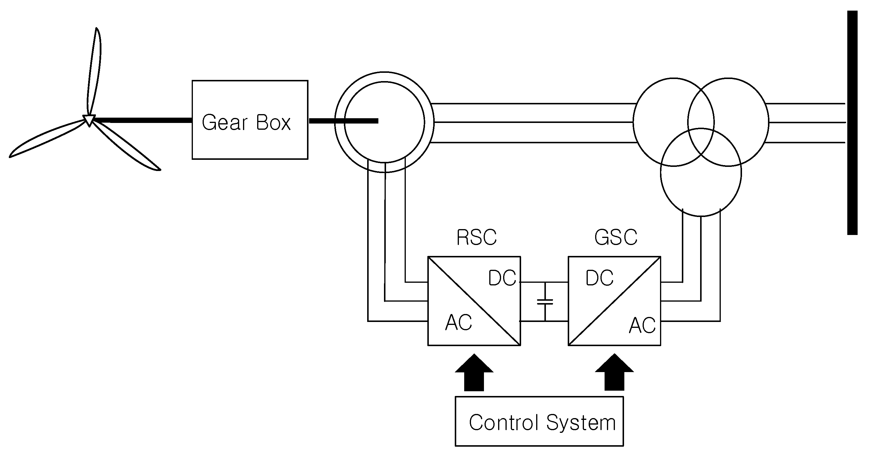
Currently, variable-speed wind turbines are mainly used for wind power generation. They can control reactive power through converter control. Common variable-speed wind turbines are classified as Type-3 and Type-4, which are also known as DFIGs and PMSGs, respectively. This study uses a Type-3 wind turbine. The Type-3 stator winding is directly connected to the low-voltage side of a transformer, while its rotor winding is connected to a bidirectional back-to-back insulated-gate bipolar transistor voltage source converter, as shown in Figure 2.
The converter helps in decoupling mechanical and electrical frequencies, and making variable-speed operation possible. Because the Type-3 Wind Turbine Generator (WTG) is equipped with a partial scale converter, the turbine cannot operate within the full range, i.e., from zero to the rated speed. However, the speed range is quite sufficient. The DFIG controls the active power and reactive power independently, through direct-quadrature-zero transformation of the converter control system. Three phase electrical quantities can be transformed into two phase quantities for ease of application. In general, the RSC controls the active and reactive power supplied to the system through the stator, and DC voltage between the rectifier and inverter is controlled through the GSC.
Reactive Power Capability of Doubly-Fed Induction Generator (DFIG)
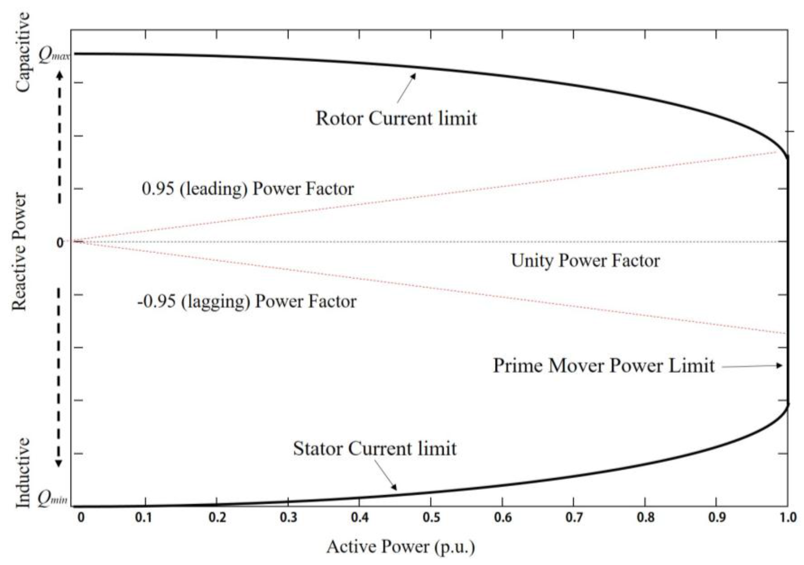
The reactive power control capability of the DFIG can be divided into two strategies. First is the supply capability, shown by the PQ capability curve of the DFIG. Second, is the reactive power capability curve of a typical synchronous generator, described by the D-curve. Some generators have reactive power supply capability even when they do not output any power. However, usually, the reactive power support ability in generators is limited due to active power operation. This is because conventional generators (CGs) have plans with minimum power generation from the operational aspect. However, in the case of DFIGs, the active power has a wide range, from 0 to the maximum power, because it reflects the aerodynamic characteristics according to the wind speed. The range of the DFIG’s reactive power support against active power is shown in Figure 3.
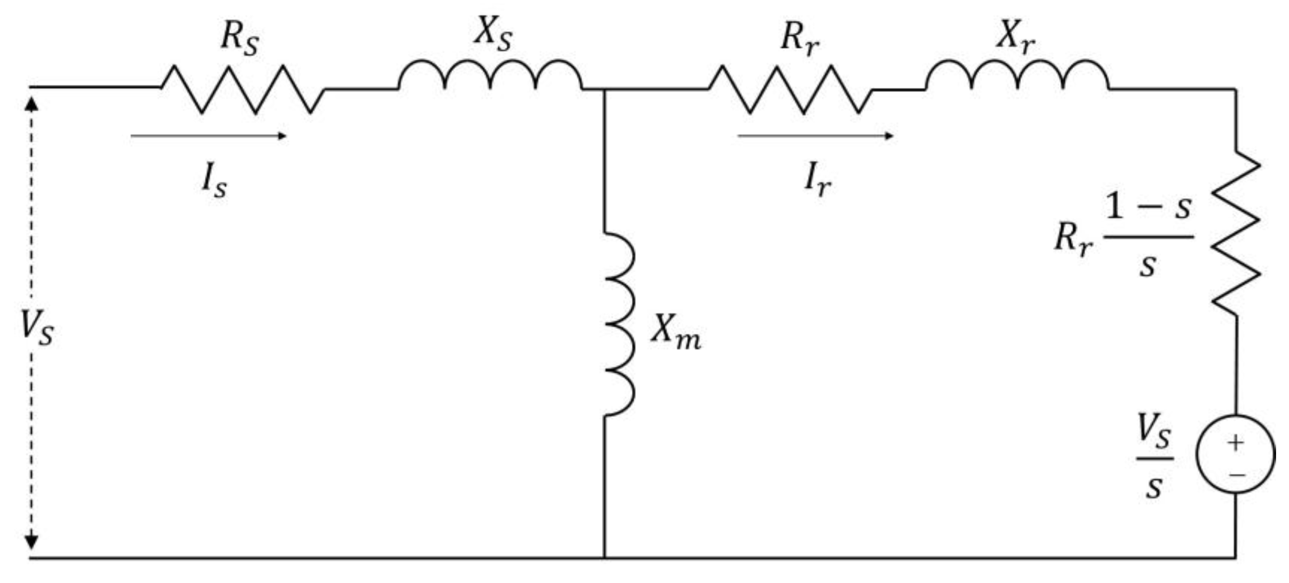
A DFIG has the above reactive power capability because of the control of the RSC converter. As shown in Figure 3, the curve is determined based on three factors: the stator current limit, rotor current limit, and mechanical limit [20,21]. Among these three factors, stator current limit, and rotor current limit mainly determine the PQ curve. The reactive power capability limit of the DFIG through the above stator current limit and rotor current limit conditions can be estimated using the equivalent circuit of DFIG in Figure 4 [22,23].
The stator voltage is set to the nominal voltage (1 p.u.), under the assumption that there is no impact of a transformer connecting a rotor and a stator in the static condition. The maximum value of reactive power supply, which depends on the rotor current limit, can be expressed by the following equation of stator voltage and rotor current. Qmax due to the rotor current limitation is determined by the apparent power of stator and the equation is as follows [21].
where Zm is the main impedance in DFIG and Zs is the stator impendence. As the equation shows, the apparent power for rotor current is determined by stator voltage and rotor current, irrespective of the slip of the DFIG. The Qmax for active power output is calculated by the above equation. The stator current limit, determining a Qmin, is calculated by the following equation for power of the rotor side.
Unlike the rotor current condition, the apparent power of the rotor converter includes the range of power of the stator. Finally, when considering the mechanical limit according to Pmax of the generator, a curve of the Figure 3 can be obtained, which is fully utilizable. On the basis of the above limits, the curve of reactive power supply capability can be produced, according to the active power range.
The second strategy is a power factor range presented in the grid code. The reactive power supply capability of a DFIG at a terminal bus generally exceeds the range of 0.95 lagging and 0.90 leading. However, the grid code limits the operation to within ±0.95 power factor. Typically, in the case of setting the power flow in a Type-3 wind turbine, the active power is first determined by the wind condition, and subsequently, the reactive power min–max value is determined by the operating power factor.
where Pg active power output of wind turbine generator, PF power factor which wants to operate.
If the power factor of the WTG is not fixed, then the values are decided according to the power factor range and value. In general, a value of 0.95, proposed in the grid code, is applied as the PF of the wind turbine. Therefore, in this paper, the reactive capability, including the power factor range in the grid code, is used to estimate the reactive power supply capability of the WPP, within the range of the minimum and maximum value of reactive power.
3. Definition of Wind Power Plant Applicable-Effective Reactive Power Reserve
3.1. Conventional Reactive Power Reserve (CRPR)
The conventional reactive reserve is used in power flow considerations [24,25,26]. The reactive power supply capability of each generator is determined by the PQ capability curve. In other words, the RPR is calculated by the difference of Qmax and Qmin between the operation point and PQ capability curve. The RPR of the entire grid is finally obtained by the sum of reactive powers of each generator, and can be numerically defined as follows
where maximum reactive power of the i-th generator, current reactive power generated by the i-th generator.
The calculation method of the reactive reserve using the CRPR does not reflect the local characteristics of the reactive power well, because it simply calculates the difference between the maximum power and the current power.
Generally, when reactive power is supplied due to a voltage dip, the reactive power, which is supported by each generator or a reactive power compensator, cannot be supplied to a specific bus because of reactive power loss at the transformer or transmission line. Therefore, the proposed Wa-ERPR is an index to judge the reactive power transfer capability of a WPP and individual CG at the POI.
3.2. Wind Power Plant Applicable-Effective Reactive Power Reserve (Wa-ERPR)
Sensitivity analysis is used to analyze the relationship between the bus and the other bus, regarding the voltage and reactive power [18,27]. The concept of effectiveness RPR applied to wind power generation is proposed as an RPR index to satisfy the LVRT conditions. The Jacobian matrix is used to determine the influence of the reactive power change of the POI due to the reactive power change of the wind turbine and the CG. Using the fast-decoupled load flow method, the P, Q, and V relationships can be linearized, as shown in the following equations
The elements of matrix are divided into the diagonal elements and the off-diagonal elements, as shown in Equations (8) and (9)
The nonlinear equation describing the reactive power change for the above voltage change can be converted into a simple linear form through the following assumption, which is adopted in real grid systems
If the above assumption and Stott’s simplifications are applied, the following equations can be obtained
The linear equation contains a B matrix, which consists of a susceptance component from the node admittance matrix in a power system. Equation (13) can be represented as an interaction formula that describes the generator bus including a WPP and target bus, which in turn include the high voltage side of the POI. Thus, the B matrix, consisting of susceptance component, can be used to express the relationship between the reactive power variation and the voltage variation of load bus, WPP, and CG linearly. Here, BG,POI and BPOI,G are the topology of generation bus and POI bus, respectively. BGG and BPOI,POI are the susceptance values according to the connection condition of the generation buses and POI bus, respectively. Thus, of the high voltage side at the POI and of the existing synchronous generator and wind farm can be obtained from the above linear equation.
Equations (14)–(16) can be reconstructed for variation of voltage at each generator buses
If the variations of the terminal voltage of generators are kept constant when in the normal state, they can be reconstructed as follows
where reactive power change of the both CGs and Wind Turbines (WTs) on the reactive power change at the POI.
The above equation helps in ascertaining the effect that the reactive power change of generators, including wind power generation, has on the reactive power change of the POI bus. In other words, a generator with the largest value of has the largest effect on the reactive power change of a POI bus. As the sensitivity matrix created from the B matrix has very small component values, the highest sensitivity value is applied, in order to reflect a significant contribution to generators, thereby identifying an RPR that can affect the POI of each generator. normalized by SQ, can be expressed as follows
where N total number of generators in the system; normalized weighting factor of the i-th generator with respect to the POI bus, SQ matrix of generator’s sensitivity.
Therefore, the proposed Wa-ERPR formulation is as follows
The physical implication of this expression is the effect of the RPR of the CG and the WPP at the POI. In the case of a WPP, the total amount of PQ capability of the WT is determined according to number of WTs, and the RPR is calculated by computing the difference between the operation point and Qmax.
3.3. Proposed Scheme of Wa-ERPR Management
When a contingency occurs, the grid side converter of the DFIG operates in the voltage regulator mode, to maintain a terminal voltage. After the fault is cleared, the voltage is recovered by the reactive power supplied to the POI bus. At this time, the degree of voltage sag and recovery time are related to both the wind farm’s participation in voltage control, and the RPR of the system. If the system is optimal, the voltage recovery is more dependent on the RPR degree of the system than the control strategy. Thus, the RPR management algorithm, which can secure sufficient RPR to meet LVRT conditions at the POI, operates as shown in Figure 5.
The B matrix is constructed based on pre-contingency system data to derive a weight factor affecting the POI. Next, the RPR is calculated by the difference between Qmax and operation point of Q of CGs. Subsequently, the RPR of a WPP is calculated by the difference between the operation point and reactive power capability curve limit of the WPP. Finally, based on the Wa-ERPR proposed in the section above, the influence of the reactive power of each generation source on the POI is ascertained.
In case of a line contingency, the topology of the system changes, which leads to a change in the B matrix and the reduction of reactive power affecting the POI. Accordingly, if an LVRT criterion is not met after a line contingency, a stable amount of Wa-ERPR needs to be secured by calculating reactive power compensation, which can affect the POI, through a comparison with the pre-contingency Wa-ERPR. In this way, the RPR at the POI can be ensured.
4. Simulation Results
4.1. System Configuration
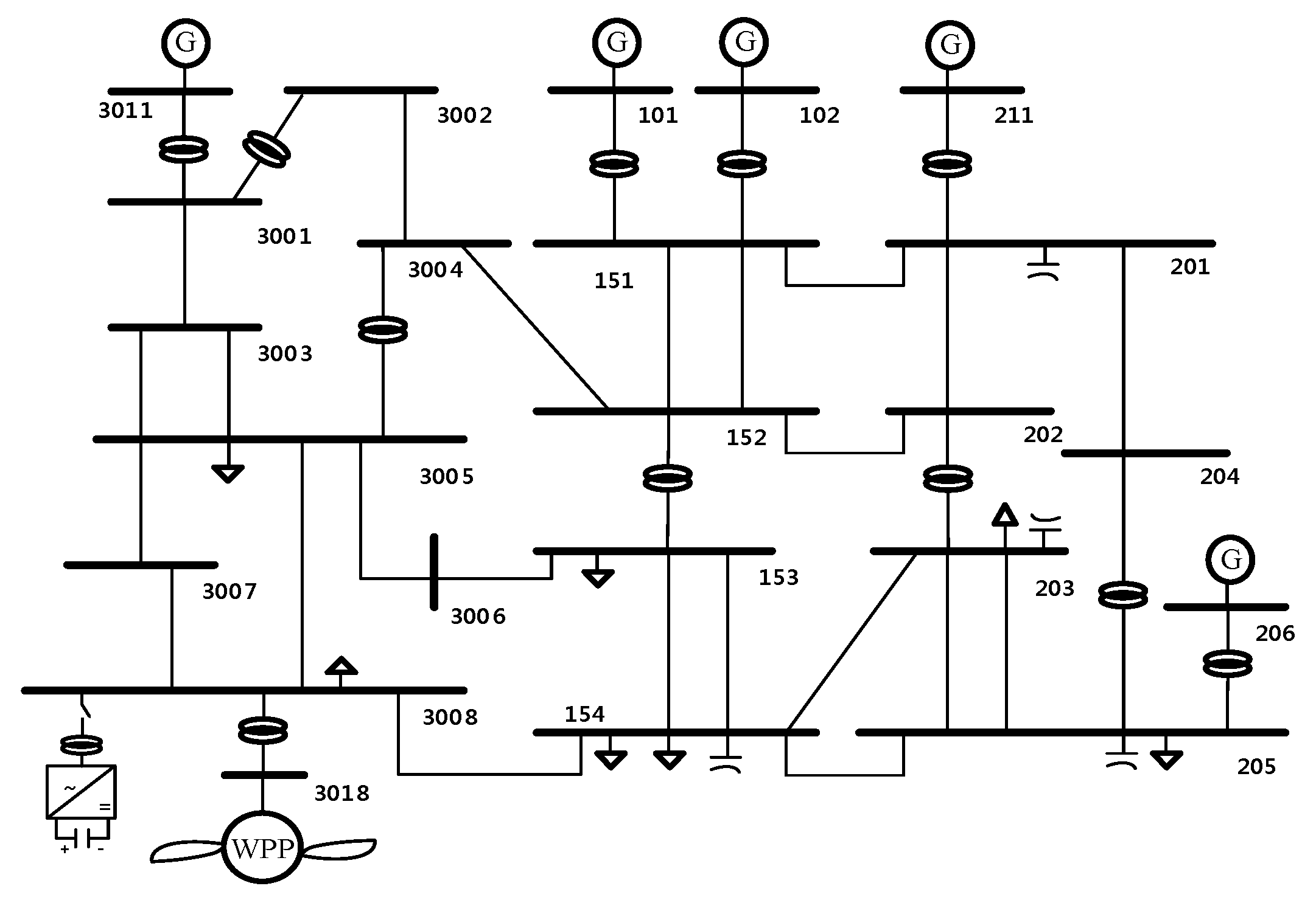
The simulation was performed in test system called SAVNW (Version 33.7), by using PSS/E [28]. The system is depicted in Figure 6. The System has six generators, its total active power is 3258.6570 MW and the installed capacity of the CGs is 4153.2502 MW. As seen in Table 1, It has eight load buses, and total amount of load is 3200 MW.
WPP are connected to Bus 3018 instead of the previous generator. The Installed capacity of the Wind power plant is modeled as 130MVA and DFIG model provided by WECC is applied [29]. The active power output is set to 100 MW and the range of reactive power is set to 0.436 p.u. to satisfy the reactive power capability within current limit [30]. If the wind farm is operated without sufficient reactive reserve, it will not satisfy the LVRT condition when a fault occurs. In order to satisfy a stable reactive reserve, extra reactive power is injected with a STATCOM device at the POI.
Dynamic voltage recovery is also related to dynamic load penetration. In this system, 50% of the entire load consists of the dynamic motor load. In order to simulate a contingency at the nearby wind farm, the contingency condition shown in Table 2 are considered:
4.2. Computation of Wa-ERPR at the Point of Interconnection
Table 3 presents the sensitivity of the wind power and CG buses for the POI. The sensitivity was normalized through the sensitivity matrix for pre-contingency and normal conditions.
The impacts on the POI in the above table assume that the same quantity of reactive power is output from a particular generator. As shown in the Table 3, the WIND-G farm connected directly to 13.8/230 kV transformer has the largest effect of reactive power on the POI. Accordingly, when the values of Wa-ERPR based on CRPR of each generator and the above weight factors are compared, the following graph is obtained.
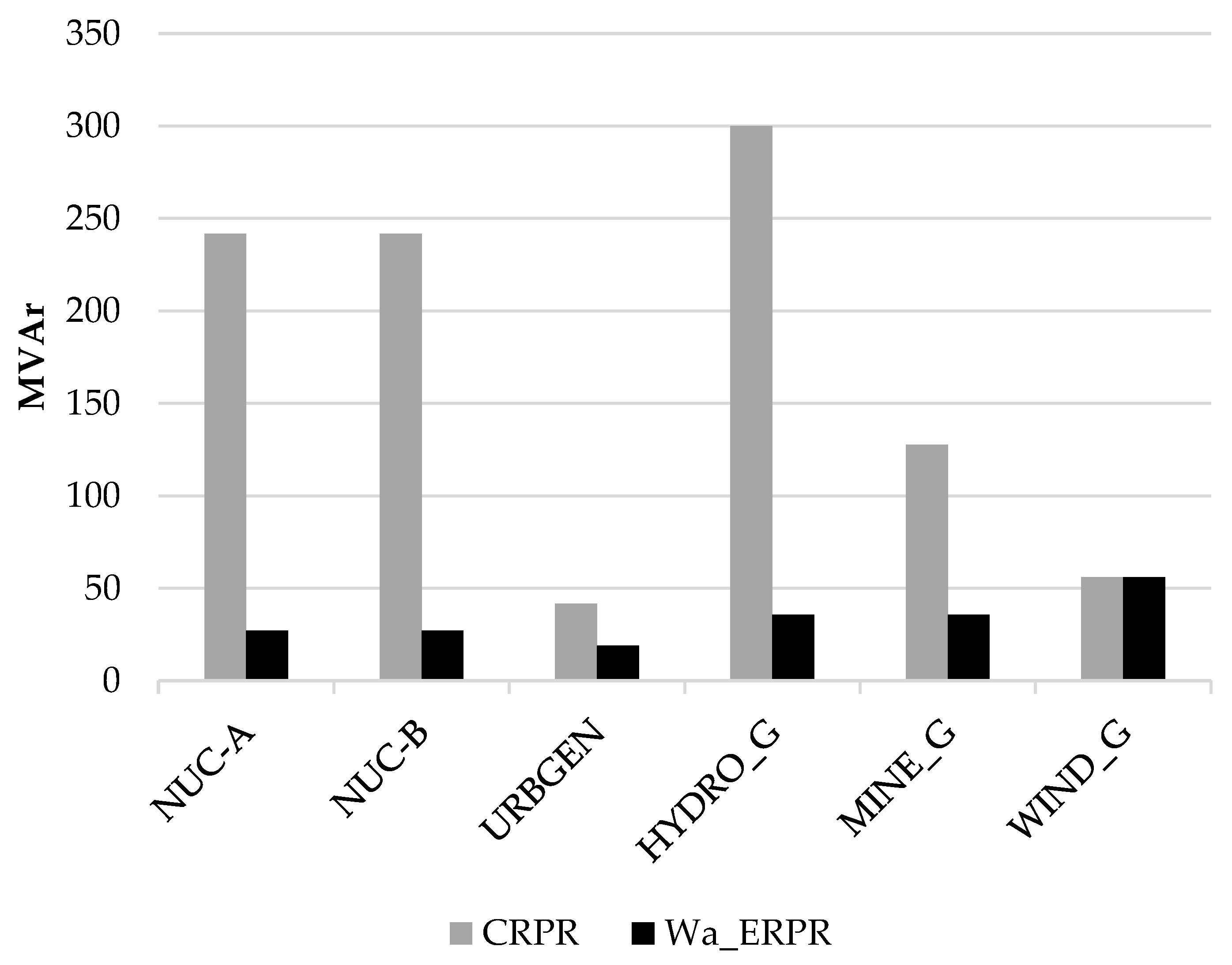
In Figure 7 and Table 4, if the RPR of the entire system is calculated in the conventional way, the result will be 1008.98 MVAr. However, this indicates only the total amount of RPR in the entire system. It is the available reactive power reserve of individual generators, not the reactive power reserve that directly affects the POI. On the other hand, when Wa-ERPR, which affects the POI, is calculated by using weight factors through the sensitivity matrix, the result is 200.34 MVAr, which is less than RPR value of each generation source. This is because the connection conditions to the POI and the line specifications are reflected, to consider the reactive power loss during the transmission process. In other words, instead of the mere comparison of a total physical quantity, the concept of electrical distance from a generation source to the POI is applied to calculate the reactive power affecting the POI.
4.3. Application of Wa-ERPR Management Scheme
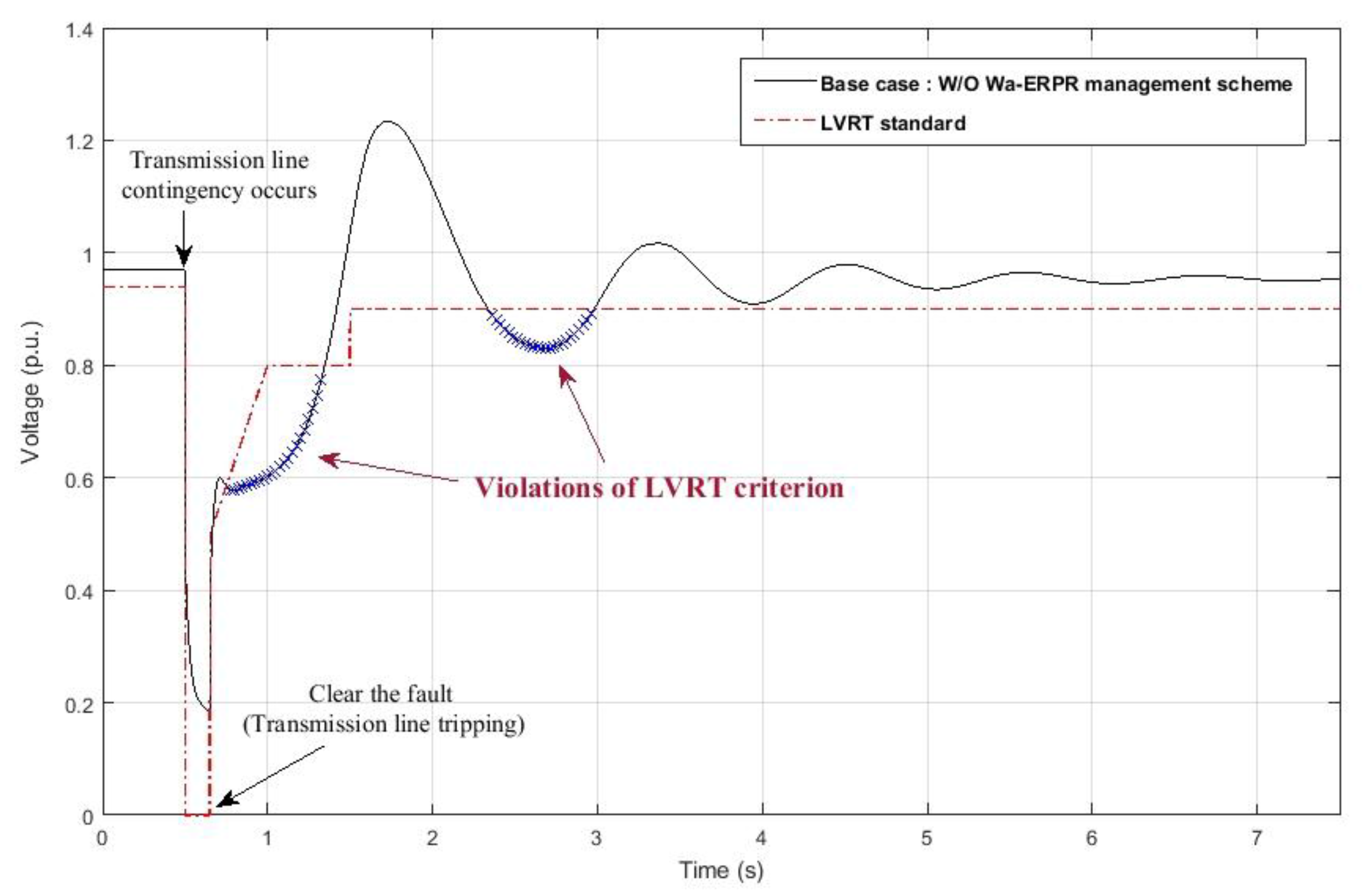
This simulation is performed in order to verify the effect of the Wa-ERPR Management Scheme in the case of a grid fault. The post-contingency conformance to LVRT is confirmed, and the RPR is calculated based on Wa-ERPR before and after contingency. In this way, the reactive power is compensated using a STATCOM connected to the POI. Our fault scenario considers 3005–3008 1ck transmission line fault. It is assumed that the fault occurs at 0.5 s and is cleared at 0.65 s.
Figure 8 shows the dynamic response of the POI voltage when the 3005–3008 line fault occurs, and the line is tripped at 0.65 s. As the line is tripped after the fault is cleared, the LVRT criterion is not met at the POI. The blue × indicates an interval that does not meet the LVRT criteria. The first section lasts for 0.5960 s, and the second section lasts for 0.64 s. This is because the voltage recovery is delayed due to insufficient RPR at the POI. Accordingly, the Wa-ERPR management scheme can be applied to calculate Wa-ERPR, and to secure the RPR at POI. After a contingency occurs, the Wa-ERPR can be calculated using the B matrix, reflecting the topology of the tripped line and calculating the RPR of a CGs and WPP.
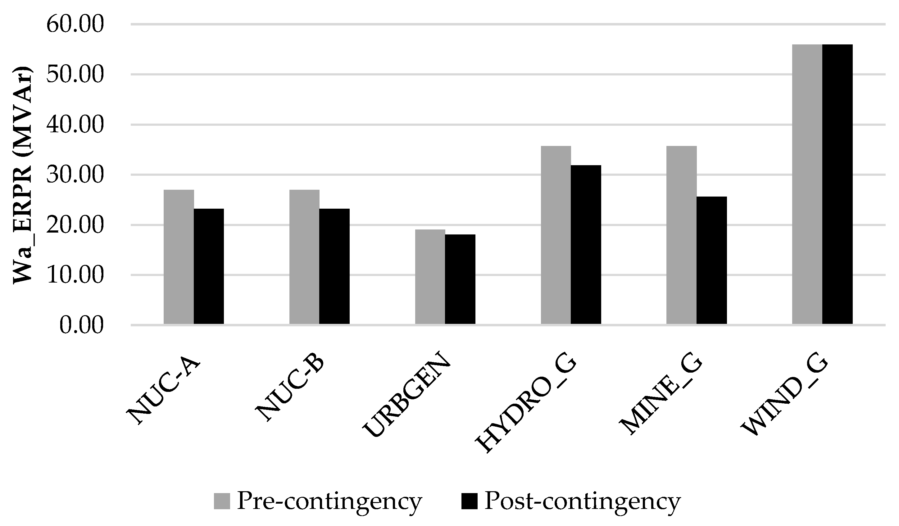
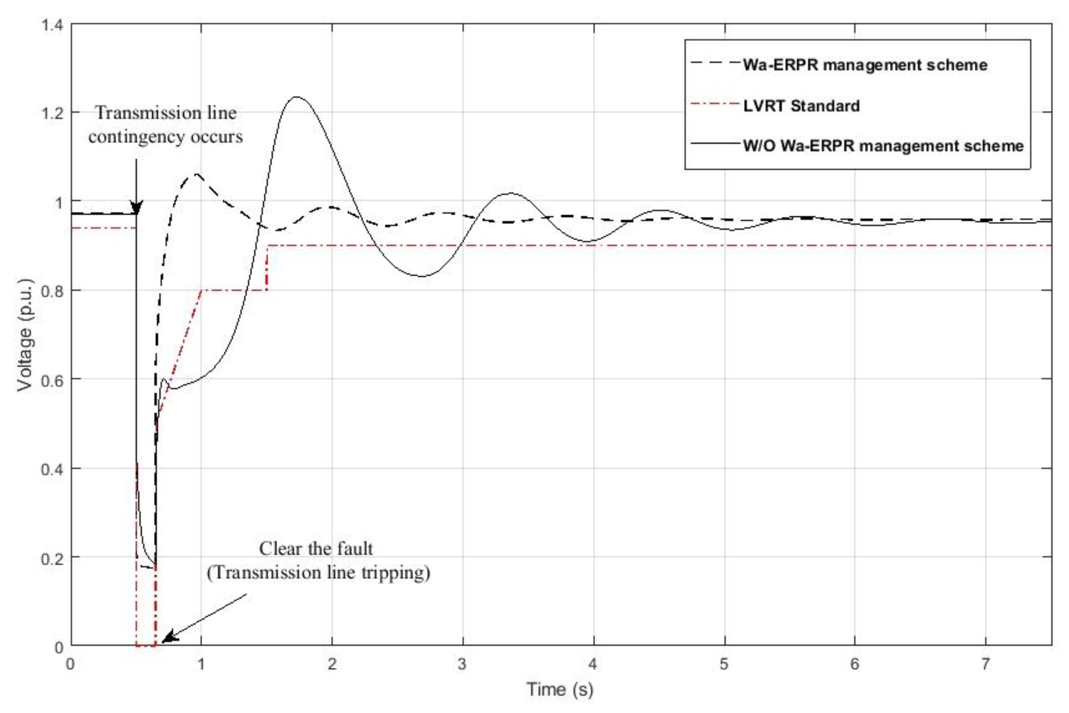
As shown in Figure 9 and Table 5, the “MINE_G” generator exhibits the largest decrease in Wa-ERPR. This generator is electrically closest to the tripped transmission line. It can be seen that the reactive power reserve, which affects the POI of the individual generators, as well as “MINE_G”, decreases with the change of system topology considering the disturbance. And it can also be seen that the voltage recovery of the remaining generators is delayed after the fault was cleared, because their Wa-ERPR values were also reduced due to impedance change during the fault. Thus, in order to secure the stable condition of Wa-ERPR level as pre-contingency, 23 MVar STATCOM is connected to the POI and supply the additional reactive power. When the Wa-ERPR management scheme was applied to calculate the reactive power compensation and compensate it, it turned out that the POI secured the adequate level of Wa-ERPR and satisfied the LVRT criterion, as shown in the Figure 10.
5. Conclusions
In this paper, an RPR management scheme that satisfies the LVRT criterion at the POI of a large-scale DFIG wind farm is proposed. Effectiveness of reactive power reserve of individual generators including wind power plant at POI can be calculated through Wa-ERPR. Along with the participation of the wind farm in voltage control, an adequate level of RPR needs to be secured with respect to the system, in order to meet the LVRT criterion for the POI. The characteristic of dynamic voltage recovery after a fault is closely related to whether the reactive power of a system is secured or not. Accordingly, the concept of Wa-ERPR to calculate the RPR of wind and CGs, as far as they affect the POI, is presented. To calculate Wa-ERPR, an equation including the B matrix with admittance information was derived, by converting the equations of Q and V changes into linear formulations. In order to compare the influence among individual generation sources, the sensitivity values were also calculated, which indicated ratio of the reactive power change of the generation source for the reactive power change of the POI, and normalized the values. In this way, range of Q for the RPR of CGs and PQ capability of wind power generators were considered, and Wa-ERPR could be calculated. The Wa-ERPR management scheme could consider the grid topological change before and after a disturbance. So, the proposed scheme computes the Wa-ERPR in pre and post contingency and calculates the amount of reactive power compensation. As a result, wind power plant satisfy the LVRT standard through STATCOM compensation for securing stable level of RPR.
Acknowledgments
This research was supported by Korea Electric Power Corporation (Grant number R17XA05-4).
Author Contributions
Hwanik Lee conceived and designed the research, conducted the simulations, and wrote the paper; Moonsung Bae contributed analysis tools and analyzed the data; and Byongjun Lee improved the theoretical part and guided the research.
Conflicts of Interest
The authors declare no conflict of interest.
References
- Flynn, D.; Rather, Z.; Ardal, A.; D’Arco, S.; Hansen, A.D.; Cutululis, N.A.; Sorensen, P.; Estanquiero, A.; Gomez, E.; Menemenlis, N. Technical impacts of high penetration levels of wind power on power system stability. Wiley Interdiscip. Rev. Energy Environ. 2017, 6, 1–19. [Google Scholar] [CrossRef]
- Huang, T.; Lu, Y.; Cai, C.; Xu, S. A New Simulation and Analysis for Low Voltage Ride through Property of Wind Farm. In Proceedings of the 2012 IEEE Power and Energy Society General Meeting, San Diego, CA, USA, 22–26 July 2012; pp. 1–6. [Google Scholar]
- Ackermann, T. Wind Power in Power Systems; John Wiley & Sons: Hoboken, NJ, USA, 2005. [Google Scholar]
- Ellis, A.; Nelson, R.; Von Engeln, E.; Walling, R.; MacDowell, J.; Casey, L.; Seymour, E.; Peter, W.; Barker, C.; Kirby, B. Reactive power performance requirements for wind and solar plants. In Proceedings of the 2012 IEEE Power and Energy Society General Meeting, San Diego, CA, USA, 22–26 July 2012; pp. 1–8. [Google Scholar]
- Gounder, Y.K.; Nanjundappan, D.; Boominathan, V. Enhancement of transient stability of distribution system with SCIG and DFIG based wind farms using STATCOM. IET Renew. Power Gener. 2016, 10, 1171–1180. [Google Scholar] [CrossRef]
- Duong, M.Q.; Grimaccia, F.; Leva, S.; Mussetta, M.; Le, K.H. Improving transient stability in a grid-connected squirrel-cage induction generator wind turbine system using a fuzzy logic controller. Energies 2015, 8, 6328–6349. [Google Scholar] [CrossRef] [Green Version]
- Zhong, C.; Wei, L.; Yan, G. Low voltage ride-through scheme of the PMSG wind power system based on coordinated instantaneous active power control. Energies 2017, 10, 995. [Google Scholar] [CrossRef]
- Shen, Y.; Cui, M.; Wang, Q.; Shen, F.; Zhang, B.; Liang, L. Comprehensive reactive power support of DFIG adapted to different depth of voltage sags. Energies 2017, 10, 808. [Google Scholar] [CrossRef]
- Kim, J.; Seok, J.-K.; Muljadi, E.; Kang, Y.C. Adaptive q–v scheme for the voltage control of a DFIG-based wind power plant. IEEE Trans. Power Electron. 2016, 31, 3586–3599. [Google Scholar] [CrossRef]
- Qiao, W.; Venayagamoorthy, G.K.; Harley, R.G. Real-time implementation of a STATCOM on a wind farm equipped with doubly fed induction generators. IEEE Trans. Ind. Appl. 2009, 45, 98–107. [Google Scholar] [CrossRef]
- Hasan, N.; Ibraheem, S.F. Dynamic performance analysis of DFIG based wind farm with STATCOM and SVC. Int. J. Emerg. Technol. Adv. Eng. 2012, 2, 461–469. [Google Scholar]
- Camm, E.; Behnke, M.; Bolado, O.; Bollen, M.; Bradt, M.; Brooks, C.; Dilling, W.; Edds, M.; Hejdak, W.; Houseman, D. Reactive power compensation for wind power plants. In Proceedings of the 2009 PES’09 IEEE Power & Energy Society General Meeting, Calgary, AB, Canada, 26–30 July 2009; pp. 1–7. [Google Scholar]
- Patel, P.P.; Patel, J.J. Application of statcom to enhance the lvrt capability of dfig based wind turbine generating system. Int. J. Innov. Res. Electr. Electron. Instrum. Control Eng. 2016, 4, 1–5. [Google Scholar]
- Nguyen, T.H.; Lee, D.-C.; Van, T.L.; Kang, J.-H. Coordinated control of reactive power between STATCOMS and wind farms for PCC voltage regulation. J. Power Electron. 2013, 13, 909–918. [Google Scholar] [CrossRef]
- Zheng, Z.; Yang, G.; Geng, H. Coordinated control of a doubly-fed induction generator-based wind farm and a static synchronous compensator for low voltage ride-through grid code compliance during asymmetrical grid faults. Energies 2013, 6, 4660–4681. [Google Scholar] [CrossRef]
- Dong, F.; Chowdhury, B.H.; Crow, M.L.; Acar, L. Improving voltage stability by reactive power reserve management. IEEE Trans. Power Syst. 2005, 20, 338–345. [Google Scholar] [CrossRef]
- Menezes, T.; da Silva, L.C.; Affonso, C.; da Costa, V.F. Mvar management on the pre-dispatch problem for improving voltage stability margin. IEE Proc. Gener. Transm. Distrib. 2004, 151, 665–672. [Google Scholar] [CrossRef]
- Choi, Y.; Seo, S.; Kang, S.; Lee, B. Justification of effective reactive power reserves with respect to a particular bus using linear sensitivity. IEEE Trans. Power Syst. 2011, 26, 2118–2124. [Google Scholar] [CrossRef]
- Seo, S.-S.; Choi, Y.-H.; Kang, S.-G.; Lee, B.-J.; Shin, J.-H.; Kim, T.-K. Hybrid control system for managing voltage and reactive power in the JEJU power system. J. Electr. Eng. Technol. 2009, 4, 429–437. [Google Scholar] [CrossRef]
- Londero, R.R.; de Mattos Affonso, C.; Vieira, J.P.A. Long-term voltage stability analysis of variable speed wind generators. IEEE Trans. Power Syst. 2015, 30, 439–447. [Google Scholar] [CrossRef]
- Lund, T.; Sørensen, P.; Eek, J. Reactive power capability of a wind turbine with doubly fed induction generator. Wind Energy 2007, 10, 379–394. [Google Scholar] [CrossRef]
- Amaris, H.; Alonso, M.; Ortega, C.A. Reactive Power Management of Power Networks with Wind Generation; Springer Science & Business Media: Berlin, Germany, 2012. [Google Scholar]
- Zhou, Z.; Qureshi, W.A.; Nair, N.-K.C. Assessment of Low Voltage Ride-Through Behaviour of Several Wind Farms with Crowbar Protection. In Proceedings of the 2013 Australasian Universities Power Engineering Conference (AUPEC), Hobart, TAS, Australia, 29 September–3 October 2013; pp. 1–5. [Google Scholar]
- Taylor, C.W. Power System Voltage Stability; McGraw-Hill: New York, NY, USA, 1994. [Google Scholar]
- Van Cutsem, T.; Vournas, C. Voltage Stability of Electric Power Systems; Springer Science & Business Media: Berlin, Germany, 1998. [Google Scholar]
- Kundur, P.; Balu, N.J.; Lauby, M.G. Power System Stability and Control; McGraw-hill: New York, NY, USA, 1994. [Google Scholar]
- Bae, M.; Lee, H.; Lee, B. An approach to improve the penetration of sustainable energy using optimal transformer tap control. Sustainability 2017, 9, 1536. [Google Scholar]
- Siemens, P. Pss/e User-Manual; Siemens Industry: Schenectady, NY, USA, 2012. [Google Scholar]
- Type, W. Wind Turbine Generator Model–Phase II. Available online: https://www.wecc.biz/Reliability/WECC-Type-3-Wind-Turbine-Generator-Model-Phase-II-012314.pdf (accessed on 20 September 2017).
- Wecc Wind Plant Dynamic Modeling Guidelines. Available online: https://www.wecc.biz/Reliability/WECC%20Wind%20Plant%20Dynamic%20Modeling%20Guidelines.pdf (accessed on 20 September 2017).
Figure 1.
LVRT standards on the Korean grid code.

Figure 2.
Configuration of Doubly-Fed Induction Generator.

Figure 3.
Reactive power capability curve of a DFIG.

Figure 4.
Equivalent circuit of DFIG.

Figure 5.
Flow chart of the Wa-ERPR management scheme.

Figure 6.
System configuration.

Figure 7.
Comparison of CRPR and proposed Wa-ERPR.

Figure 8.
Base case: Voltage at the POI in case of contingency.

Figure 9.
Calculation of Wa-ERPR pre- and post-contingency.

Figure 10.
Proposed scheme: Voltage at the POI in case of contingency.


Table 1.
Wind power plant and CGs data.
| Bus Number | Name | (MW) | (MVAr) |
|---|---|---|---|
| 101 | NUC-A | 750 | 58.14 |
| 102 | NUC-B | 750 | 58.14 |
| 206 | URBGEN | 800 | 558.31 |
| 211 | HYDRO_G | 600 | −100 |
| 3011 | MINE_G | 256 | 72.34 |
| 3018 | WIND_G | 100 | −0.02 |
Table 2.
Contingency scenario for study case.
| Contingency | Fault Occurrence Time (s) | Fault Clearing Time (s) |
|---|---|---|
| 3005–3008 1ck transmission line | 0.5 | 0.65 |
Table 3.
Weight factor of individual generators based on sensitivity matrix.
| NUC-A | NUC-B | URBGEN | HYDRO_G | MINE_G | WIND_G | |
|---|---|---|---|---|---|---|
| 0.1116 | 0.1116 | 0.4565 | 0.1191 | 0.2796 | 1 |
Table 4.
Comparison of CRPR and proposed Wa-ERPR value.
| Bus Number | Name | CRPR (MVAr) | Wa-ERPR (MVAr) |
|---|---|---|---|
| 101 | NUC-A | 241.86 | 26.98 |
| 102 | NUC-B | 241.86 | 26.98 |
| 206 | URBGEN | 41.68 | 19.03 |
| 211 | HYDRO_G | 300 | 35.73 |
| 3011 | MINE_G | 127.65 | 35.69 |
| 3018 | WIND_G | 55.92 | 55.93 |
| Total | - | 1008.98 | 200.34 |
Table 5.
Wa-ERPR value at the POI pre- and post-contingency.
| Bus Number | Name | Pre-Contingency Wa-ERPR (MVAr) | Post-Contingency Wa-ERPR (MVAr) |
|---|---|---|---|
| 101 | NUC-A | 26.98 | 23.2 |
| 102 | NUC-B | 26.98 | 23.2 |
| 206 | URBGEN | 19.03 | 18.7 |
| 211 | HYDRO_G | 35.73 | 31.88 |
| 3011 | MINE_G | 35.69 | 25.6 |
| 3018 | WIND_G | 55.93 | 55.93 |
| Total | 200.34 | 177.89 |
© 2017 by the authors. Licensee MDPI, Basel, Switzerland. This article is an open access article distributed under the terms and conditions of the Creative Commons Attribution (CC BY) license (http://creativecommons.org/licenses/by/4.0/).
Share and Cite
MDPI and ACS Style
Lee, H.; Bae, M.; Lee, B. Advanced Reactive Power Reserve Management Scheme to Enhance LVRT Capability. Energies 2017, 10, 1540. https://doi.org/10.3390/en10101540
AMA Style
Lee H, Bae M, Lee B. Advanced Reactive Power Reserve Management Scheme to Enhance LVRT Capability. Energies. 2017; 10(10):1540. https://doi.org/10.3390/en10101540
Chicago/Turabian StyleLee, Hwanik, Moonsung Bae, and Byongjun Lee. 2017. "Advanced Reactive Power Reserve Management Scheme to Enhance LVRT Capability" Energies 10, no. 10: 1540. https://doi.org/10.3390/en10101540
Note that from the first issue of 2016, this journal uses article numbers instead of page numbers. See further details here.