The Characteristics of Methane Combustion Suppression by Water Mist and Its Engineering Applications


1
Department of Safety & Science Engineering, Henan Polytechnic University, Jiaozuo 454003, China
2
The Collaborative Innovation Center of Coal Safety Production of Henan Province, Henan Polytechnic University, Jiaozuo 454003, China
3
Henan Key Laboratory of Prevention and Cure of Mine Methane & Fires, Jiaozuo 45403, China
4
State Key Laboratory of Coal Mine Disaster Dynamics and Control, Chongqing University, Chongqing 400044, China
*
Author to whom correspondence should be addressed.
Energies 2017, 10(10), 1566; https://doi.org/10.3390/en10101566
Submission received: 7 September 2017
/
Revised: 22 September 2017
/
Accepted: 9 October 2017
/
Published: 11 October 2017
Abstract
:To safely mine coal, engineers must prevent gas combustion and explosions, as well as seek feasible and reasonable techniques to control for these types of incidents. This paper analyzes the causes and characteristics of methane combustion and explosions. Water mist is proposed to prevent and control methane combustion in an underground confined space. We constructed an experiment platform to investigate the suppression of methane combustion using water mist for different conditions. The experimental results showed that water mist is highly effective for methane flame inhibition. The flame was extinguished with water mist endothermic cooling. However, the annular regions of water vapor around the fire played a vital role in flame extinction. Water from the evaporating mist replaces the oxygen available to the fuel. Additionally, the time required for fuel ignition is prolonged. For these reasons, the water particle action to flame surface is reinforced and the fuel’s reaction with air is delayed. As a result, flame stretching and disturbances occur, which serve to extinguish the flame. Engineering application tests were carried out in the goaf, drill hole and upper-corner to investigate the prevention and control of methane gas combustion, with the results showing a good application effect.
1. Introduction
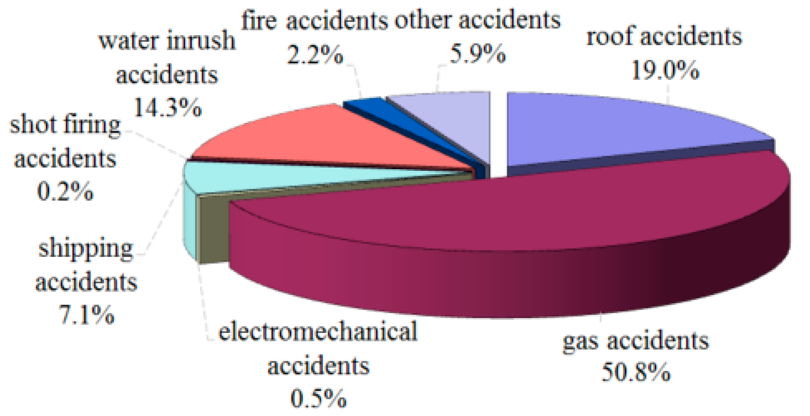
The economy of China has developed rapidly, and the demand for coal is increasing the intensity of coal mining. This leads to accidents during coal mining, especially gas related disasters. Generally speaking, coal mine gas disasters take three forms: (1) combustion and explosion disasters, with mine crashes resulting from gas combustion and explosions; (2) coal and gas outburst disasters from high pressure gas outbursts from the coal seam; and (3) asphyxia due to high gas concentrations. According to statistics, gas disasters have accounted for 50.8% of coal mine disasters in 2012, as shown in Figure 1 [1]. Therefore, gas accidents are one of the key problems that need to be solved urgently in coal mining.
Mining conditions are complex in an underground coal mine. Gas is contained in coal seams, and its main composition is methane. In recent years, gas combustion accidents have occurred frequently, partially due to a lack of prediction and control technology. For example, on 12 July 2011, the Shendong Coal Corporation suffered a gas combustion accident in working face 22,113 in the Cuncao tower mine. On 12 April 2011, a third underground roadway experienced a gas combustion accident in the Zhengxin Mining Industry Development Co. On 8 May 2010, an accident resulting from methane combustion in the Well Bay Coal Mine in Hubei left 10 people dead. On 1 April 2010, nine people were killed and one was wounded in a methane combustion accident in the Quanzigou coal mine [2]. According to incomplete statistics, these methane combustion accidents taking place in the mining face, drill hole and upper-corner have caused a large number of casualties and significant economic losses.
Fire suppression tests involving water mist have long been reported. Water mist was studied to suppress methane explosions, pool fires, poly fires, cooking oil fires, and so on [3,4,5,6,7,8]. Some comparisons may be found in the literature on experiments and computations in confined spaces or in pipelines [9,10,11]. The water mist with additives will inhibit the fire effect and will be different from the conventional water mist [12,13]. The CH4 combustion in oxygen-enriched air and combustion-induced rapid phase transition as a novel combustion mode to involving this fuel as well as other fuels—the oxidation of which produces water were researched [14,15,16,17]. However, few studies have focused on the open space suppression of methane combustion in coal mines and its engineering applications.
Therefore, presently, there is a lack of relevant technology to prevent and control methane gas combustion in a coal mine. This paper describes experiments and theoretical analyses regarding the use of water mist to control methane gas combustion in the goaf, drill hole and upper-corner. We analyzed water mist interactions with gas combustion during drilling and the water mist and gas flow fields in the upper-corner of the working face, as well as designed a release device for water mist and investigated its application. Finally, emphasis is placed on the effect that the water mist has on methane fire suppression in coal mines.
2. Analysis of the Process of Methane Combustion and Explosion
In China, coal mine methane combustion and explosion accidents mainly take place in the goaf, upper corner and drilling hole. The frequent occurrence of underground methane combustion accidents is due to sufficient oxygen and a certain amount of ignition energy. Coal mining makes it relatively easy to satisfy these two conditions, but ignition energy is the harder condition to generate. Many scholars have performed experimental research and have suggested that ignition sources include spontaneous combustion of the residual coal in the goaf, collisions between caved rock from the roof and metal objects that produce sparks and ignite the methane, and collisions and friction from caved rock that results in sparks. Furthermore, the energy release associated with rock body collisions produces high temperatures, leading to gas ignition. Additionally, roof strata fractures cause a significant piezoelectric difference on the fracture surface, resulting in sparks being produced from collisions with anchor cables, which is still the main cause of methane combustion and explosions [18,19,20,21]. Energy from the collision and friction from falling rocks is the most likely culprit for methane accidents in the goaf or upper-corner. Spontaneous combustion of coal is the main source of ignition for gas explosions in a closed area, and the frictional heat of the drill pipe and coal body can cause methane combustion during drilling.
3. Experiment System
3.1. Experimental Equipment
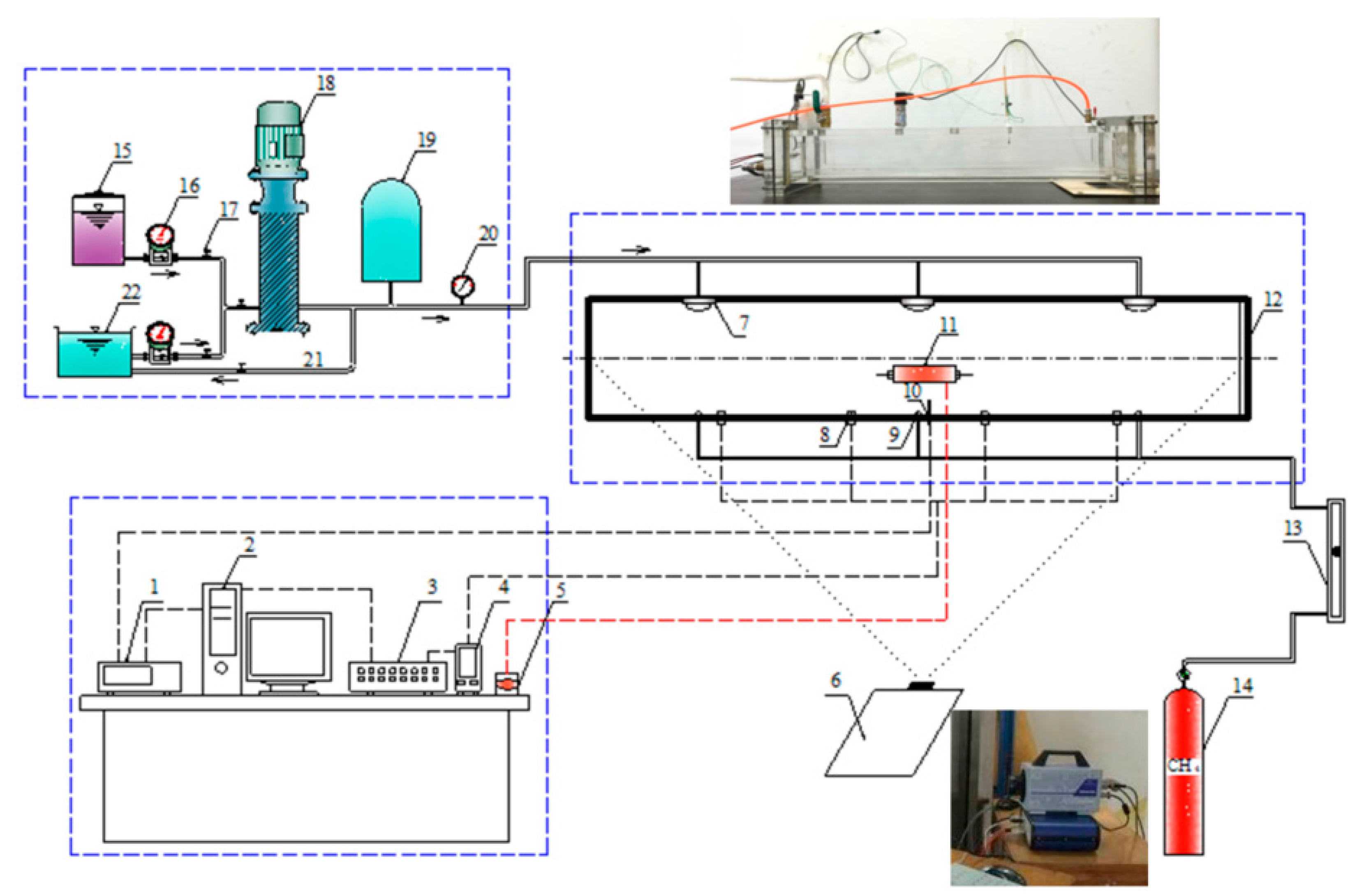
To understand the phenomenon of a gas combustion explosion in a coal mine, a gas combustion experimental system equipped with a water mist suppression system was established in the laboratory [22]. This system was composed of five parts: a combustion reaction chamber, fuel supply system, a water mist system, and a computer integrated display system, including test instruments, sensors and working parameters. The experimental system is shown in Figure 2.
The main body of the combustion reaction chamber is a rectangle, with dimensions of 2.0 m × 0.3 m × 0.3 m. The setup used toughened glass with a pressure-releasing device located at two ends. A gas release port, ignition system, temperature sensor and water mist nozzles were set up in the combustion chamber.
The working platform comprised the data acquisition system, which was composed of a combustion analyzer, thermocouple measuring instrumentation and a high-speed camera.
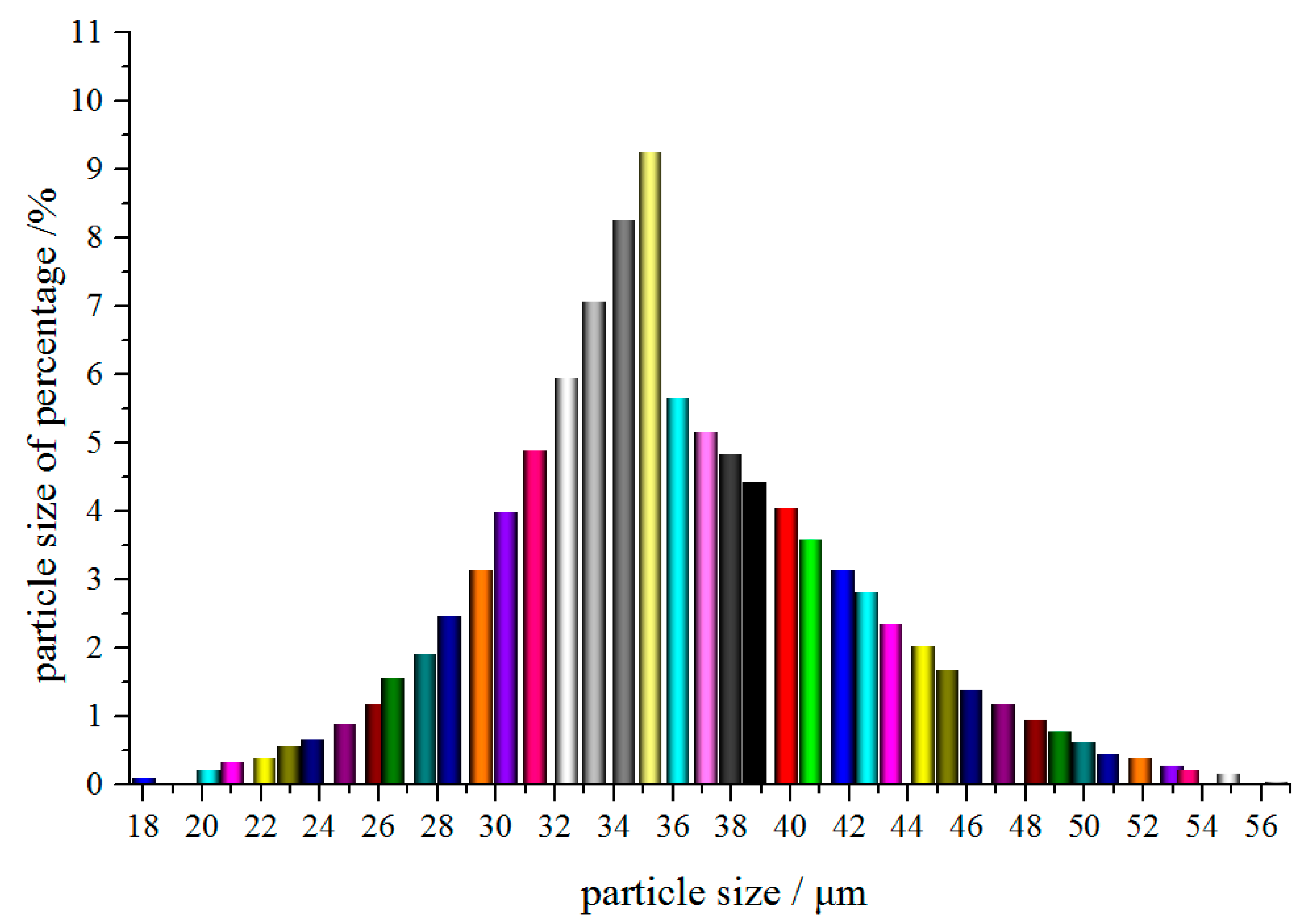
The fuel supply system provided methane and the igniter used DC high voltage electric spark ignition. The water mist system atomized a certain ratio of water and additive to fine droplets using an atomizing nozzle with the help of a high-pressure pump. The water mist size distribution was measured using a laser droplet size analyzer, as shown in Figure 3. The largest proportion was determined to be in the range from 30 to 36 μm.
3.2. Experiment Process and Condition
Three release ports were set up in the chamber, with one used for the burning experiment. The thermocouples were arranged in the upper center of the release ports. Specifically, the thermocouples were set up along the center line moving upward at intervals of 8 cm and were called thermocouples No. 1, 2, and 3. The gas concentration was 90%, the fuel flow rate was 100 mL/min, the flux from the water mist atomization was 100–200 mL/s, and the average particle size was 35 μm.
The experimental procedures included first choosing a gas release port in the combustion reaction chamber, closing the other release valves, connecting the pipes, and fixing the position of the thermocouples. Afterwards, the flue gas analyzer was opened and proofread and the gas supply system was opened prior to ignition. The sprayed water mist was activated when a sufficient amount of methane had combusted. Collection of gas was achieved using an air pump, and analysis of gases was performed using the flue gas analyzer. Changes in the flame structure and temperature were observed as part of this process. During the gas explosion experiment, the gas concentration in the combustion chamber was adjusted to 9.5%. The ignition device was activated and the experiments were conducted before and after applying water mist, with data recorded in detail. The experiments were carried out in two stages: one was free gas combustion, and the other was ignition and gas explosion in the presence of water mist in the atmosphere.
4. Experimental Results and Discussion
4.1. Analysis of Flame Temperature after Application of Water Mist
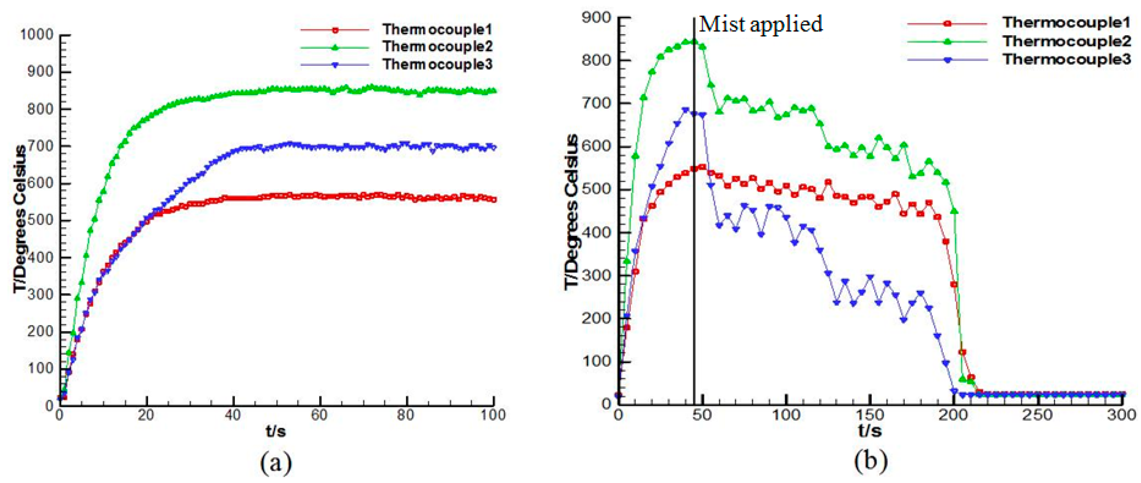
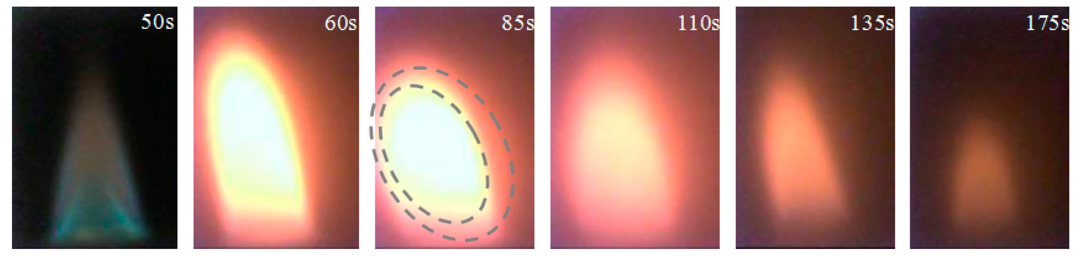
Variations in the flame temperature of methane gas combustion before and after applying water mist were compared as part of the experiments, as shown in Figure 4. The temperature of the monitoring points remained stable and increased when gas burned freely. The flame temperature appeared to exhibit different degrees of reduction after the application of water mist. This indicated that the evaporation of water mist suppressed the thermal radiation from the flame after contacting water mist. As a result, the temperature dropped from a maximum of 826 °C to 680 °C. Due to the flow rate of water mist initially being only 100 mL/s, the temperature decreased slowly. At 180 s, a large amount of water mist was entrained by the plume into the flame area when the flow rate increased to 200 mL/s. The flame lost the ability to spread and the temperature decreased in the smoke layer around the flame. There was a greater amount of evaporation as the water mist encountered the heat, inhibiting the supply of oxygen to the flame center and diluting the oxygen concentration around the flame. The reduction of oxygen and the temperature decrease reduced the speed and intensity of the combustion reaction. Ultimately, the fire was extinguished. The evolving flame process after the application of water mist is shown in Figure 5.
Figure 5 describes the changing process of the methane gas combustion flame that was extinguished by the application of water mist. The flame was quickly extinguished as the water mist flow rate increased at 180 s. This result agreed with the changes in the flame temperature as measured by the thermocouples. The area and height of the flame decreased as the water mist flow rate increased, and the flame was eventually extinguished. The flame was disturbed and widened when water mist reached its surface. Over this time, water mist started to decompose and formed water vapor, obscuring the flame surface. The flame length decreased as the water mist flow rate increased and formed a closed water vapor loop around the flame. The closed water vapor loop displaced oxygen on the surface of the flame, suppressing the methane gas reaction. The result of the changing process included changes in the flame color from blue to yellow—transitioning from dim blue through bright yellow to a blurred orange-yellow and finally dimming—as well as changes in the flame shape, which became compressed, shortened, recompressed and then extinguish.
4.2. Analysis of the Interaction between the Water Mist and Flame
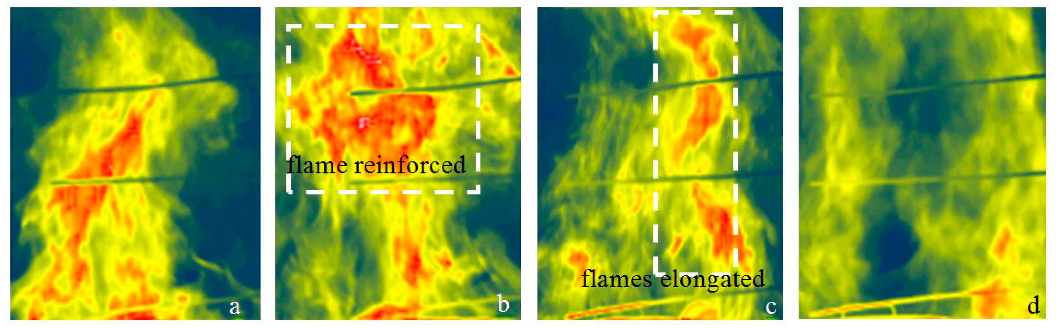
The interactions between the water mist and flame were examined using infrared thermal imaging for the different experimental conditions. Figure 6 shows variations in the flame structure in each region during the interaction of the water mist with the flame.
The water mist had a significant influence on the methane combustion flame. Upon the application of water mist, the flame experienced a state of severe turbulence and more violent combustion occurred suddenly, which is reflected in increases in the high temperature area of the flame, as shown by the dotted line in Figure 6b. Many researchers have also described this phenomenon [23,24,25]. One possible explanation was that the burning rate of fuel was accelerated by the turbulence; as water mist continued to be applied and disturbance caused, the degree of turbulence was further enhanced, the flame stretched and elongated, and the discontinuous regions widened. Meanwhile, as a result of the heat of gas combustion being absorbed by the water mist vaporized, the temperature of the flame gradually reduced until fire extinguishment.
4.3. The Influence of Methane Gas Explosive Pressure by Water Mist with Additives
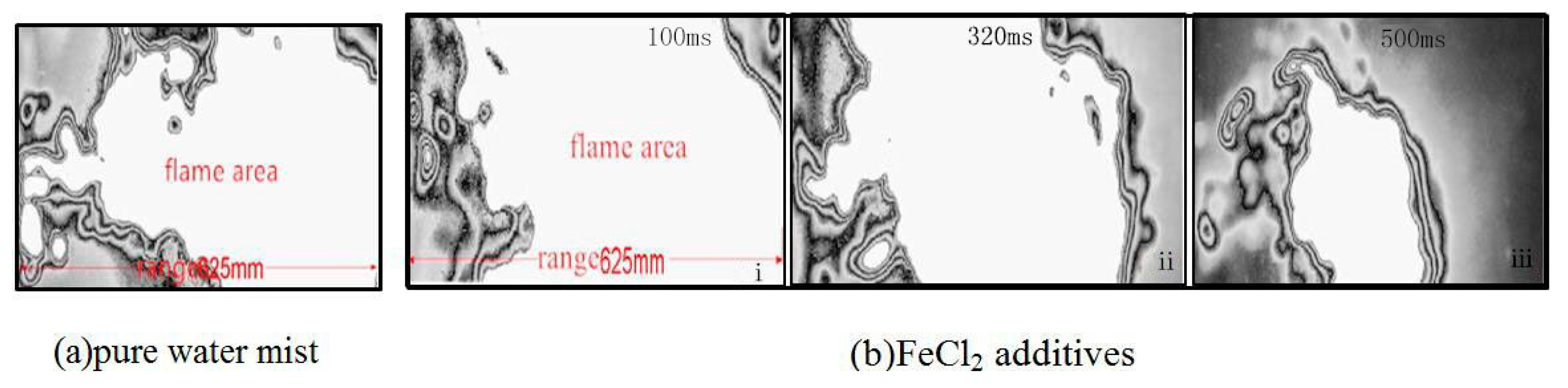
Figure 7 shows screenshots of the spread characteristics of the gas explosion flame in water mist, with and without 0.8% FeCl2 additive. The screenshots were taken from the most intense methane combustion area in the water mist zone. In the zone exposed to water mist with FeCl2, the flame area of the explosion dwindled gradually, as shown in Figure 7b(i–iii). These images correspond to Figure 7b(i) 100 ms, Figure 7b(ii) 320 ms, and Figure 7b(iii) 500 ms. This indicates that the flame radiation intensity and diffusion capacity gradually decreased. There are significant differences between Figure 7b(iii) and water mist without FeCl2. The flame area, radiation, propagation distance and suppression time significantly decreased, with the flame spread distance decreasing by 179 mm. This also illustrated that water mist containing the FeCl2 additive had a significant suppression effect on the flame.
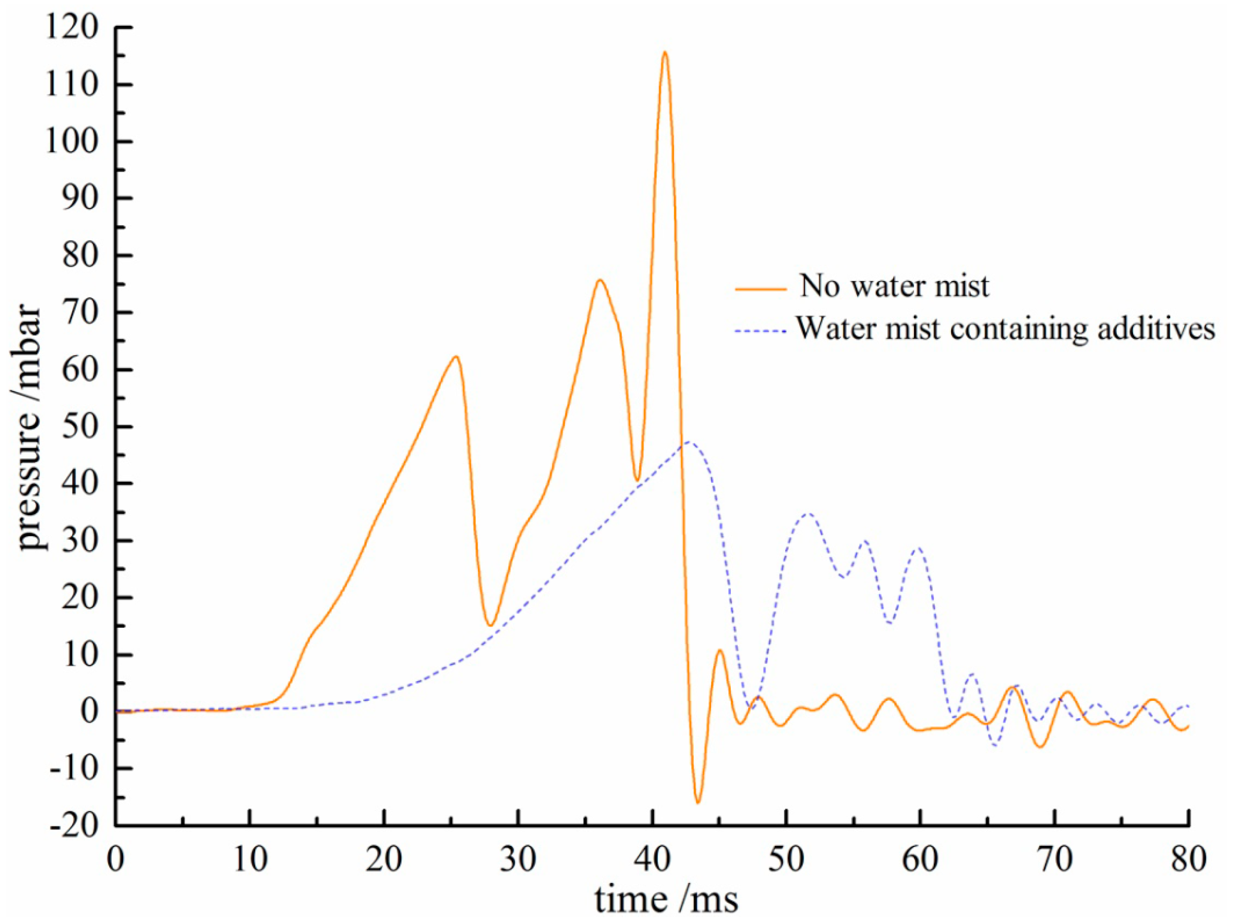
Comparison tests were performed varying the gas explosive pressure both with and without water mist, as shown in Figure 8. For water mist containing FeCl2 additive, the maximum explosion pressure is only 46 mbar, when without water mist, the maximum explosion pressure is 116 mbar, this maximum explosion pressure was 2.5 times more than the water mist environment condition. This showed that water mist had a significant suppressive effect on the explosive pressure and can play an important role in disaster prevention [26].
5. The Mechanism for Suppressing Methane Combustion Using Water Mist
5.1. The Effect of Endothermic Cooling
Due to the fine droplet size and uniform distribution the water mist, it evaporated into water vapor and absorbed a significant amount of heat upon encountering the high temperature flame and smoke flow. As a result, the outer high temperature layer of the flame became thinner and the temperature around the flame decreased rapidly as it was surrounded with more water vapor. Additionally, the burning rate of the flame also decreased, and the area and the height of the flame became smaller. In the late stage of water mist application, the droplets were sucked into the flame area, and then, the evaporation of a large amount of water mist absorbed a great deal of heat within the fire area, decreasing the overall flame temperature and causing it to die out. Therefore, the endothermic cooling from application of water mist played an important role in the fire suppression process.
5.2. The Effect of Oxygen Replacement
The quadratic law of single droplet evaporation for water mist is described in Equation (1) [11]:
where the is existence time for a droplet, D is diameter of a droplet, and kv is droplet evaporation constant.
There are two effects caused by water mist after it reaches the flame area. A portion of the droplet evaporates when contacting the heat around the flame, and the other part of the droplet passes through the heat region of the flame to directly reach the surface of the flame. The droplet evaporation constant kv was determined depending on the droplet density, droplet absorption heat capacity and the flame temperature.
Therefore, small droplets would be entrained in the fire plume in the upper part of the flame zone after the application of water mist and evaporate rapidly from the high temperature flame. The droplets are characterized by being endothermic, of small size, having a high specific surface area and a large propensity for evaporation. To account for the decrease in the ambient temperature, the droplets near the flame could stay entrained in the air longer, meaning that the volume mass fraction of droplets increased and the amount of water vapor evaporating was also increasing. A high concentration of water vapor will form a closed circle on the outside of flame area, replacing the air around the flame and reducing the amount of oxygen around the flame [21].
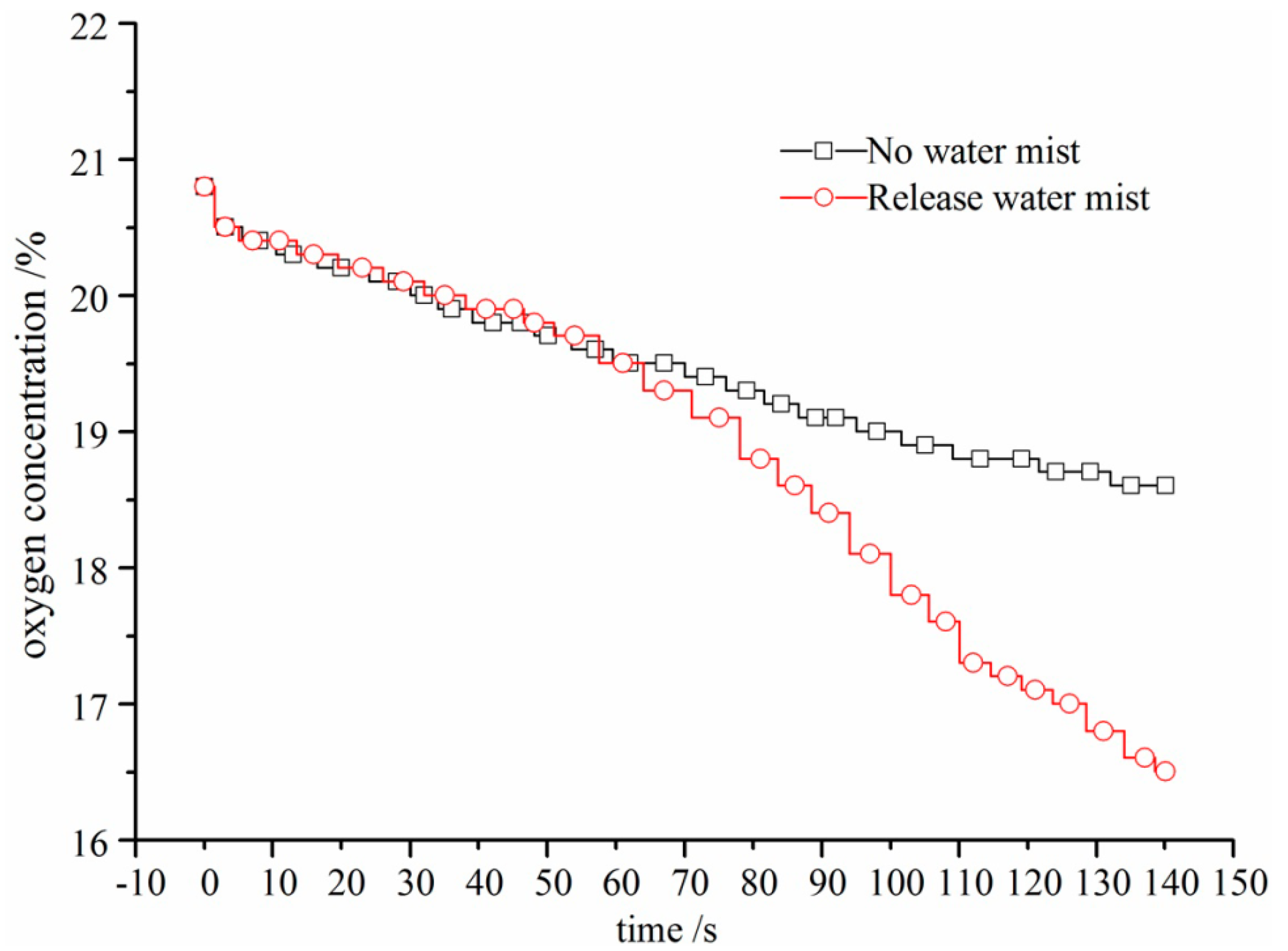
The changes in oxygen composition as a result of the application of water mist were compared as part of the experiment, as shown in Figure 9. In the free combustion state, only a small change in the oxygen concentration was observed. For water mist, the oxygen concentration was found to slowly decrease, followed by a drastic decrease after gas burning 75 s; the oxygen concentration can decrease to 16.4% in the experiment. The volume expansion of water mist as a result of evaporation inhibited the supply of oxygen and thus inhibition flame propagation.
5.3. Changes in the Ignition Energy
The ignition source in a coal mine is mainly from sparks caused by friction from direct collisions among rocks, collisions between rocks and anchor cables, high temperatures caused by friction between the borehole and coal, coal spontaneous combustion, among others. The release of water mist caused the relative humidity of the entire combustion chamber to increase to as much as 96% during the experiment. The ignition device could not ignite the methane gas when the concentration was greater than 10%, with a flashover phenomenon being observed only a few times. This illustrated that water mist restricted the temperature of the mixed gas around the electric spark to be less than the critical point for ignition cooling and heat absorption. The end result was that the gas could not be ignited in this experimental condition. Therefore, the use of extremely small droplets of water mist increased the humidity in the danger zone containing highly concentrated gas; the delay period of gas ignition was changed. The increase in humidity had a direct impact on the friction spark. The additional frictional ignition energy was insufficient to ignite the surrounding gas. Therefore, the possibility of methane gas combustion was greatly reduced. Hence, the ignition source can be nullified by releasing water mist in an area of potential gas combustion in a coal mine.
5.4. The Effect of a Heterogeneous Chemical Reaction
Water mist containing chemical additives can quickly suppress the flame and explosion. However, in addition to the physical inhibition effect, there is another chemical inhibition effect. The chemical additives used contain FeCl2. The anion and cation of the chlorine and ferrous ions precipitated from FeCl2 combine with free radicals of H+, O2− and OH− produced by methane combustion and explosions, causing these free radicals produced by combustion to be continuously destroyed [27]. The reaction process is as follows:
Fe2+ + 2OH− → Fe(OH)2;
Fe(OH)2 + 2H+ → Fe2+ + 2H2O;
Cl− + RH → R− + HCl;
HCl + OH− → Cl− + H2O.
Fe(OH)2 + 2H+ → Fe2+ + 2H2O;
Cl− + RH → R− + HCl;
HCl + OH− → Cl− + H2O.
The chain reaction for a methane combustion explosion would be weakened gradually by increasing the consumption rate of the generated free radicals and the decrease in the free radical growth rate. This causes the combustion process to become inhibited and be extinguished. In addition, the formation of anti-solvent Fe(OH)2 repelling fuel becomes wrapped in the periphery of the burning fuel and prevents the transport of heat radiation to unburned gas, further inhibiting flame propagation [28].
6. Engineering Application and Analysis
6.1. Prevention and Control Technology for Methane Gas Combustion in Goaf
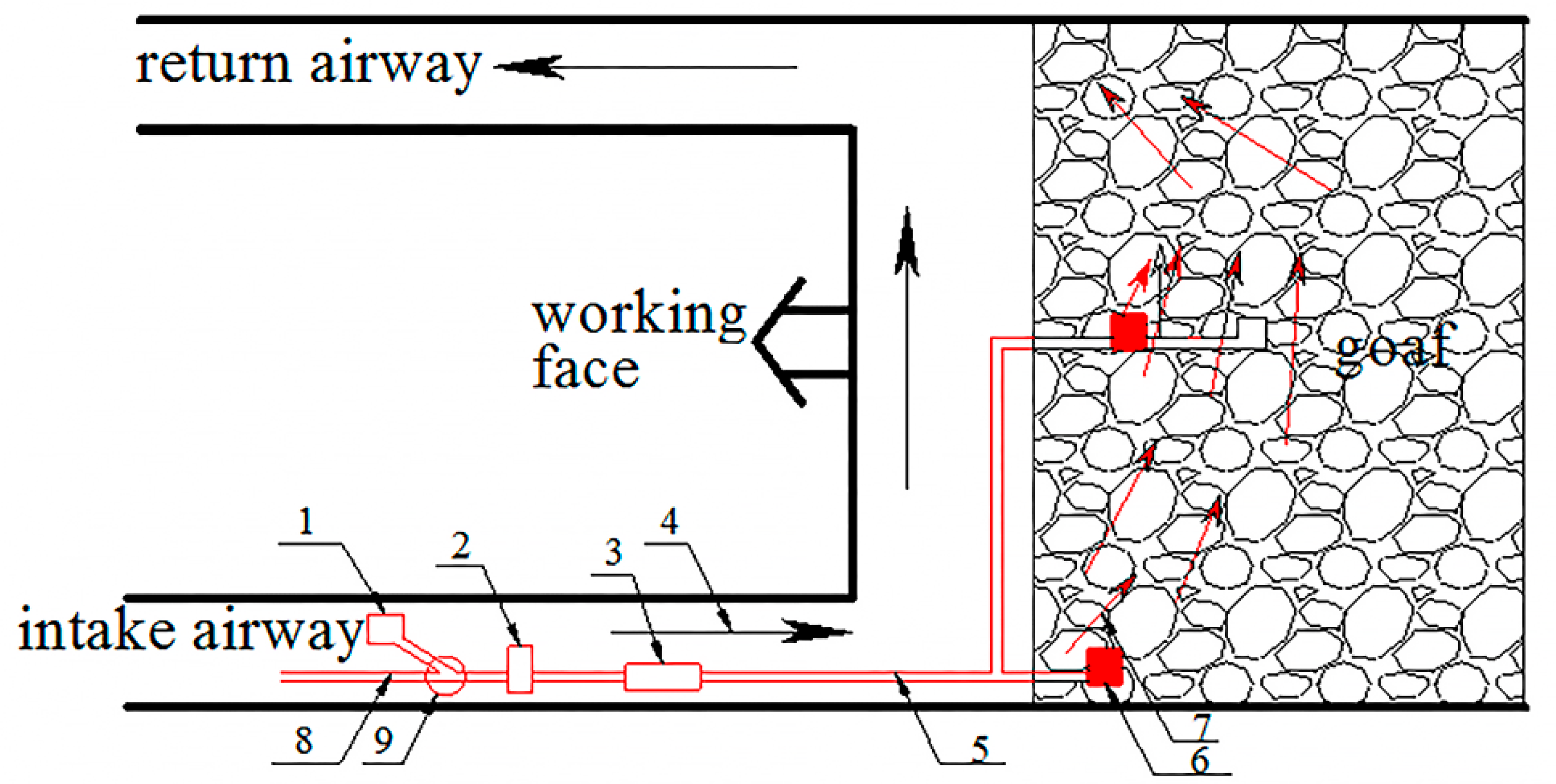
During continuous mining of a working surface, a large amount of pressure-relieved methane gas pours from the working face and goaf. The concentration can reach more than 20% as gas continuously accumulates. When coal mining roof weighting occurs, either collisions between hard rocks from the falling roof or collisions between rocks and anchor cables can produce sparks to ignite high concentrations of gas, leading to the constant threat of methane gas combustion. Therefore, we designed prevention and control measures for gas combustion in a goaf through the release of water mist. Release positions were located at the bottom-corner and the middle of the working face. The water mist droplet size was 40 µm and the pressure was 2 MPa. Specific technical measures are shown in Figure 10.
The water passed through a pre-embedded pipe transport to the deeper goaf, and through nozzle spray to form water mist; the water mist drifted into the deeper goaf along with air leakage in goaf areas as a result of the small droplet size and good flow abilities. For high temperature coal seams, the heat storage environment is destroyed by water mist evaporation. Simultaneously, water mist was adsorbed on the surface of the rock body after drifting in the goaf, changing the rock body hardness and reducing the tendency for collisions to result in high-temperature sparks, greatly decreasing the probability of methane gas combustion. To a certain extent, this could achieve the effect of preventing and controlling the occurrence of a disaster in a coal mine. As shown in Table 1, all parameters were measured from the upper corner both before and after the release of water mist in the goaf.
From Table 1, we see that data detected from the upper-corner changed (in particular, estimates for the amount of air leakage) after applying water mist in the goaf, especially as a result of the change in relative humidity. Although the increase of relative humidity could not significantly change the gas explosion limits, it played a role in the methane gas and oxygen reaction process, increasing ignition energy, extending the ignition lag and suppressing the methane gas explosion.
6.2. Prevention and Control Measures for Drilling Gas Combustion
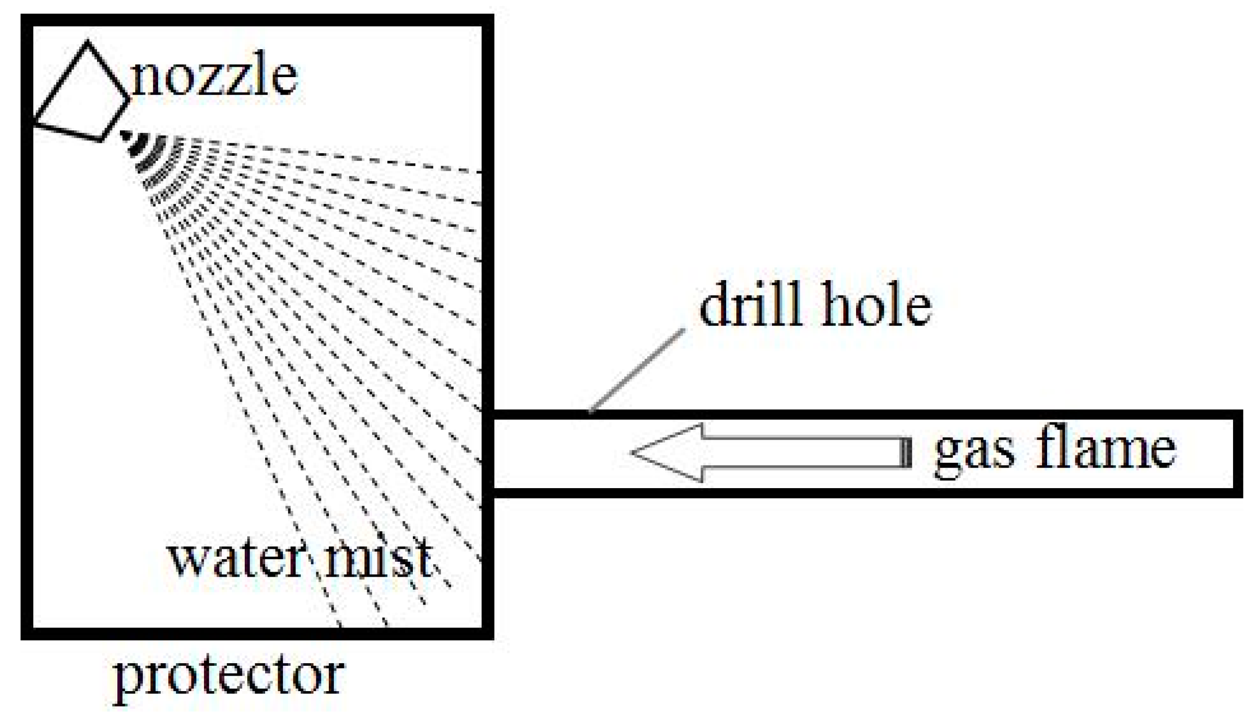
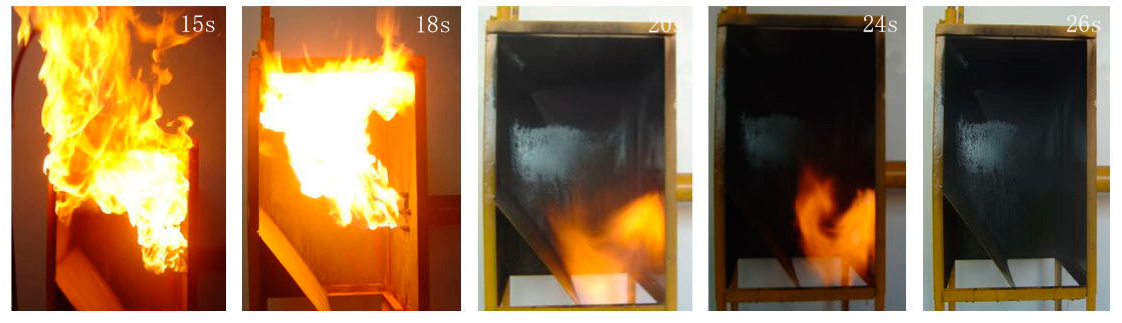
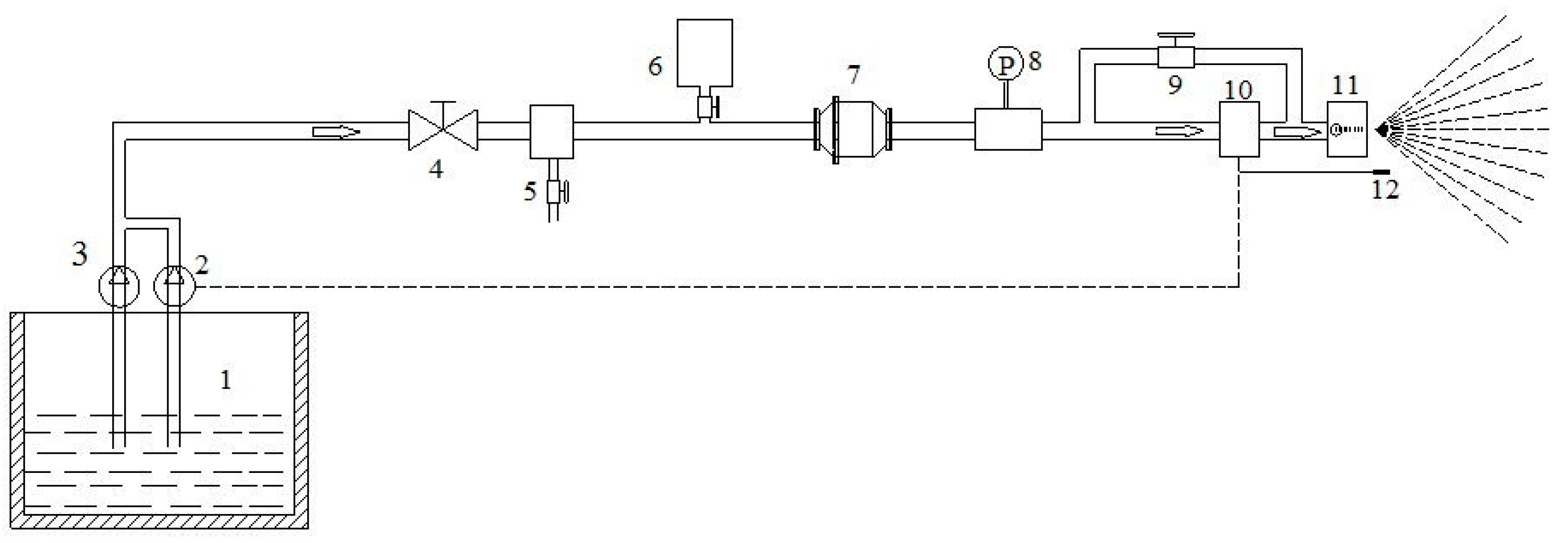
It is very important to control for disasters during gas extraction from boreholes. During drilling, it is a simple matter to ignite gas from the high temperatures inside the borehole caused by the friction between the drill pipe and coal body. Similarly, methane combustion can easily occur from wind-force discharge cinders. To address this problem, water mist was introduced into the drilling hole. Because of the complexities of drilling underground, we could not carry out field testing directly. Drilling hole gas combustion suppression experiments using water mist were carried out in this work. An experimental schematic diagram is shown in Figure 11, and the specific experimental process is shown in Figure 12.
The release of the mist was carried out using a spray working pressure of 1.6 MPa after a methane flame was ejected from the hole at a speed of 10 m/s; the gas concentration was 90% and ignition was positioned in the borehole outlet. After the methane started to fully burn, although the fire was large, it was controlled using a water mist flow of 1.8 L/min from only one nozzle and was completely extinguished in 6 s. As a result, this method is confirmed to perform well for gas flame suppression and extinction.
6.3. Prevention and Control Measures in the Upper-Corner of the Working Face
Most coal mining faces in China use U-type ventilation. A portion of the air flow is directed into the goaf and emitted from the upper-corner. In most cases, methane gas accumulates in the upper-corner due to poor ventilation. It is easy to cause a fire or gas explosion; this problem has affected safety in the working face and is one of the major problems in coal mining. For this reason, an automatic release water mist system was developed and positioned in the upper corner, as shown in Figure 13. The water mist system was activated automatically to protect against high concentrations of gas after the concentration reached a certain degree.
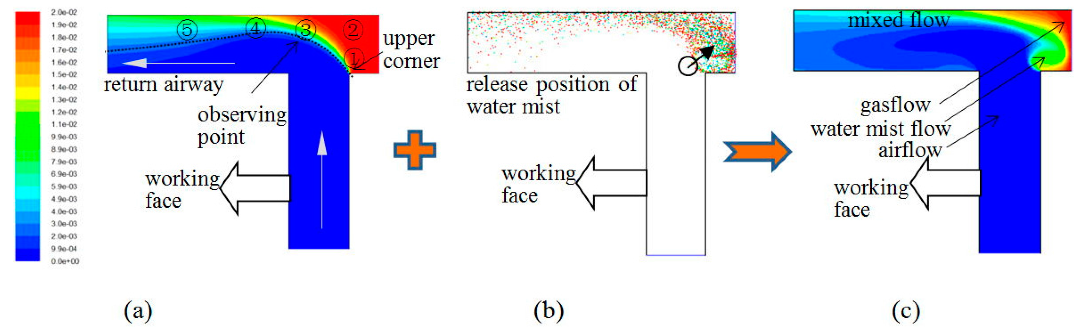
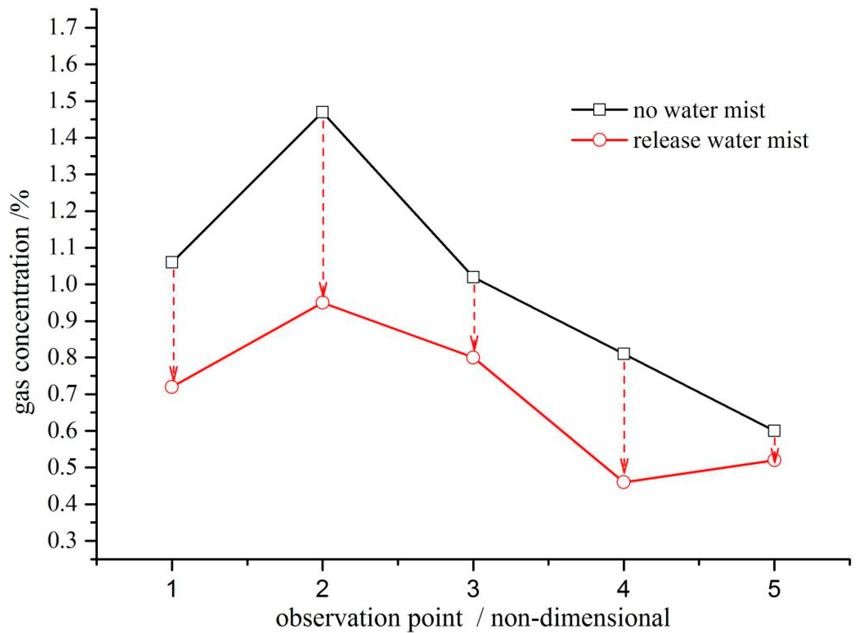
Using a discrete phase model of Fluent-software, for our simulated conditions: air leakage from the goaf was 85 m3/min, gas content was 2%, water mist spray pressure was 1.6 MPa, the flux was 120 mL/s; at last, we obtained the relationship between flow field, water mist field and gas field in the upper-corner, as shown in Figure 14. We undertook an engineering investigation in the eighth coal mine in the Pingdingshan mining group company. The accumulation of gas in the upper corner was prevented by the application of the water mist due to the disturbance and dilution of the flow field. The results were obtained showing the inhibition of the ignition energy and the prevention of methane combustion or a partial explosion. We arranged five observation points in the working face of the upper-corner, as shown in Figure 14a. We observed the contrast under the conditions of changing gas concentration with or without water mist conditions; specific changes in the gas concentration at each observation point are shown in Figure 15.
During the experiments, water mist was released from four nozzles arranged in a ring shape in the pipe. The distribution of gas measured in each point changed greatly from the strong disturbance and dilution caused by water mist. The gas concentration around the measurement point exhibited a wavelike decrease. Additionally, in the high concentration gas area, an atmosphere of water mist droplets containing the additives was formed, achieving security against high concentrations of gas. In addition, after the release of water mist, the gas concentration in the upper-corner decreased, with the largest drop reaching 37.8%, indicating that the flow of water mist can change the state of the gas flow field and suppress the methane gas accumulation from the upper-corner. Finally, in the high concentration gas area, the coverage of water mist on the rocks made it more difficult to ignite the gas. For these reasons, the working face has not been shut down from gas combustion and explosions, and the release of water mist is making the mining working face safer for coal mining.
7. Discussion
The process of using water mist to suppress fires through changes in temperature, pressure, oxygen, and flame structure was investigated under different conditions, with the results applied in the goaf, drilling and the upper-corner to prevent and control methane gas combustion. The primary conclusions from this work are as follows:
- (1)
- The release of water mist can disturb the flame by rapid decalescence and vaporization, which cools and lowers the flame temperature.
- (2)
- Water mist evaporated and formed a closed spray circle around the outside of the flame area, effectively restricting oxygen around the flame, lowering the oxygen concentration in the combustion zone and suppressing fire spread.
- (3)
- Water mist can effectively reduce the pressure of a methane gas explosion and prevent disasters from further expanding.
- (4)
- For a flame ejection speed of 10 m/s from a borehole, the release of a water mist flow of 1.8 L/min results in the borehole flame being extinguished within 6 s.
- (5)
- After the release of water mist, the gas concentration in the upper-corner of the working face decreased, with the largest drop reaching 37.8%. This process achieved positive results in engineering applications.
Acknowledgments
This work was carried out with funding from the National Natural Science Foundation of China (Grant Nos. 51304070, 51674103, U1361205), science and technology key project of Henan province (No. 162102210219), and the Doctoral Science Foundation of Henan Polytechnic University. The authors wish to thank these organizations for their support. They also wish to thank the readers and editors for their constructive comments and suggestions to improve the manuscript.
Author Contributions
Rongkun Pan and Zejun Xiao conceived and designed the experiments; Rongkun Pan performed the experiments; Rongkun Pan and Zejun Xiao analyzed the data; Minggao Yu contributed analysis tools; Zejun Xiao wrote the paper.
Conflicts of Interest
The authors declare no conflict of interest.
References
- Pan, R.K.; Cheng, Y.P.; Yuan, L.; Yu, M.G.; Dong, J. Effect of bedding structural diversity of coal on permeability evolution and gas disasters control with coal mining. Nat. Hazards 2014, 73, 531–546. [Google Scholar] [CrossRef]
- Niu, C.; Shi, L.Q.; Xiao, L.L. Study on accidents classification of coal mine from 2001 to 2013. Saf. Coal Mines 2015, 46, 208–211. [Google Scholar]
- Yu, M.G.; Wan, S.J.; Xu, Y.L.; Zheng, K.; Liang, D. The influence of the charge-to-mass ratio of the charged water mist on a methane explosion. J. Loss Prev. Process Ind. 2016, 41, 68–76. [Google Scholar] [CrossRef]
- Jenft, A.; Collin, A.; Boulet, P.; Pianet, G.; Breton, A.; Muller, A. Experimental and numerical study of pool fire suppression using water mist. Fire Saf. J. 2014, 67, 1–12. [Google Scholar] [CrossRef]
- Yoshida, A.; Kashiwa, K.; Hashizume, S.; Naito, H. Inhibition of counter flow methane/air diffusion flame by water mist with varying mist diameter. Fire Saf. J. 2015, 71, 217–225. [Google Scholar] [CrossRef]
- Brewster, M.Q. Evaporation and condensation of water mist/cloud droplets with thermal radiation. Int. J. Heat Mass Transf. 2015, 88, 695–712. [Google Scholar] [CrossRef]
- Yao, B.; Cong, B.H.; Qin, J.; Chow, W.K. Experimental study of suppressing Poly(methyl methacrylate) fires using water mists. Fire Saf. J. 2012, 47, 32–39. [Google Scholar] [CrossRef]
- Qin, J.; Yao, B.; Chow, W.K. Experimental study of suppressing cooking oil fire with water mist using a cone calorimeter. Int. J. Hosp. Manag. 2004, 23, 545–556. [Google Scholar] [CrossRef]
- Yoshida, A.; Okawa, T.; Ebina, W. Experimental and numerical investigation of flame speed retardation by water mist. Combust. Flame 2015, 162, 1772–1777. [Google Scholar] [CrossRef]
- Yao, B.; Fan, W.; Liao, G. Interaction of water mists with a diffusion flame in a confined space. Fire Saf. J. 1999, 33, 129–139. [Google Scholar] [CrossRef]
- Adiga, K.C.; Hatcher, R.F.; Sheinson, R.S.; Williams, F.W.; Ayers, S. A computational and experimental study of ultra water mist as a total flooding agent. Fire Saf. J. 2007, 3, 150–161. [Google Scholar] [CrossRef]
- Liu, J.H.; Cong, B.H. Experimental study on critical fire concentration of water mist containing additives. J. China Univ. Min. Technol. 2011, 40, 116–119. [Google Scholar]
- Rumminger, M.D.; Reinelt, D.; Babushok, V.; Linteris, G.T. Numerical study of the inhibition of premixed and diffusion flames by iron pentacarbonyl. Combust. Flame 2002, 128, 145–164. [Google Scholar] [CrossRef]
- Almerinda, D.B.; Francesco, C.; Valeria, D.S.; Ernesto, C.; Gennaro, R. Anomalous behavior during explosions of CH4 in oxygen-enriched air. Combust. Flame 2011, 158, 2214–2219. [Google Scholar]
- Almerinda, D.B.; Francesco, C.; Valeria, D.S.; Ernesto, C.; Gennaro, R. Reconsidering the flammability diagram for CH4/O2/N2 and CH4/O2/CO2 mixtures in light of combustion-induced rapid phase transition. Chem. Eng. Sci. 2012, 84, 142–147. [Google Scholar]
- Ernesto, S.; Anna, B.; Francesco, C.; Valeria, D.S.; Almerinda, D.B. Explosions of syngas/CO2 mixtures in oxygen-enriched air. Ind. Eng. Chem. Res. 2012, 51, 7671–7678. [Google Scholar]
- Almerinda, D.B.; Francesco, C.; Valeria, D.S.; Ernesto, C.; Gennaro, R. Effect of diluents on rapid phase transition of water induced by combustion. AIChE J. 2012, 58, 2810–2819. [Google Scholar]
- Yu, W.; Miao, X.X.; Mao, X.B. Analysis of the heating—Up mechanism in the course of the rock ram. Chin. J. Rock Mech. Eng. 2005, 24, 1535–1538. [Google Scholar]
- Qin, Y.J.; Jiang, W.Z.; Wang, X.Y. Determination the source of goaf gas explosion (combustion). Saf. Coal Mines 2005, 36, 35–37. [Google Scholar]
- Wu, Y.Y.; Zhou, X.Q.; Zhu, H.Q. Research of environmental factors for gas igniting by sparks induced by high-speed strike. J. China Univ. Min. Technol. 2003, 32, 186–188. [Google Scholar]
- Pan, R.K.; Cheng, Y.P.; Yu, M.G.; Lu, C. Experimental study of new technology for preventing gas combustion in mining face. J. China Coal Soc. 2012, 37, 1854–1858. [Google Scholar]
- Yu, M.G.; Wan, S.J.; Xu, Y.L.; Zheng, K.; Liang, D. Suppressing methane explosion over pressure using a charged water mist containing a NaCl additive. J. Nat. Gas Sci. Eng. 2016, 29, 21–29. [Google Scholar] [CrossRef]
- Birwa, S.K.; Mishra, D.P. Measurements of the visible flame height of a swirl-stabilized kerosene jet diffusion flame. Combust. Explos. Shock Waves 2015, 51, 416–423. [Google Scholar] [CrossRef]
- Rashwan, S.S.; Ibrahim, A.H.; Abou-Arab, T.W.; Nemitallah, M.A.; Habib, M.A. Experimental investigation of partially premixed methane–air and methane–oxygen flames stabilized over a perforated-plate burner. Appl. Energy 2006, 169, 126–137. [Google Scholar] [CrossRef]
- Deilamani, K.S.; Assar, M. A new approach to determine relieving temperature and thermodynamic behavior of trapped single and multi-phase fluid exposed to fire. J. Loss Prev. Process Ind. 2015, 36, 134–145. [Google Scholar] [CrossRef]
- Zheng, L.G.; Lü, X.S.; Zheng, K. Influence of ignition position on overpressure of premixed methane-air deflagration. CIESC J. 2015, 66, 2749–2756. [Google Scholar]
- Yu, M.G.; Li, X.L.; Ma, K.S.; Duan, Y.L.; Hao, Q. Experiments and mechanism of using spray mist with additives to extinguish kerosene pool firet. J. Henan Polytech. Univ. 2006, 25, 433–436. [Google Scholar]
- Kuang, K.S.; Cong, B.H.; Liao, G.X. Experimental study on effectiveness of water mist fire suppression with ferrous chloride additive. Fire Saf. Sci. 2005, 14, 21–27. [Google Scholar]
Figure 1.
The proportion of larger accidents in coal mining in China in 2012.

Figure 2.
Experimental system for suppressing gas combustion using water mist: 1 data acquisition unit, 2 computer, 3 signal converter, 4 signal acquisition, 5 ignition device, 6 high speed camera, 7 nozzle, 8 pressure sensor, 9 gas release mouth, 10 temperature sensor, 11 igniter, 12 combustor, 13 float flow meter, 14 gas bottle, 15 additive, 16 flow meter, 17 valve, 18 high pressure pump, 19 energy accumulator, 20 pressure gage, 21 wet return, 22 water tank.

Figure 3.
The water mist field histogram.

Figure 4.
Variation of flame temperature before and after releasing water mist: (a) no water mist and (b) with water mist.
Figure 4.
Variation of flame temperature before and after releasing water mist: (a) no water mist and (b) with water mist.

Figure 5.
Fire suppression process using water mist.

Figure 6.
Flame structural changes during combustion: (a) normal combustion flame, (b–d) changing flame characteristics after water mist.
Figure 6.
Flame structural changes during combustion: (a) normal combustion flame, (b–d) changing flame characteristics after water mist.

Figure 7.
Comparison of the effect of the water mist, (a) with and (b) without the FeCl2 additive, on gas combustion.
Figure 7.
Comparison of the effect of the water mist, (a) with and (b) without the FeCl2 additive, on gas combustion.

Figure 8.
Combustion explosion pressure changes with time.

Figure 9.
Variation tendencies in oxygen concentration after application of water mist.

Figure 10.
Prevention and control measures of gas combustion in the goaf using water mist: 1 additives, 2 high pressure pump, 3 filter screen, 4 airflow direction, 5 delivery pipeline, 6 water mist nozzle, 7 release direction, 8 main feedwater pipe, and 9 water tank.
Figure 10.
Prevention and control measures of gas combustion in the goaf using water mist: 1 additives, 2 high pressure pump, 3 filter screen, 4 airflow direction, 5 delivery pipeline, 6 water mist nozzle, 7 release direction, 8 main feedwater pipe, and 9 water tank.

Figure 11.
Experimental schematic diagram of the drilling hole gas fire suppressed by water mist.

Figure 12.
Experimental images of the drilling hole gas flame suppressed by water mist.

Figure 13.
Upper-corner gas combustion and explosion suppression system: 1 closed water tank, 2 backup pump, 3 main pump, 4 shut-off valve, 5 pressure relief valve, 6 additives, 7 mixed filter, 8 manometers, 9 hand control valve, 10 automatic starting valves, 11 Nozzle, and 12 gas detection probe.
Figure 13.
Upper-corner gas combustion and explosion suppression system: 1 closed water tank, 2 backup pump, 3 main pump, 4 shut-off valve, 5 pressure relief valve, 6 additives, 7 mixed filter, 8 manometers, 9 hand control valve, 10 automatic starting valves, 11 Nozzle, and 12 gas detection probe.

Figure 14.
Release of water mist in the upper-corner: (a) gas flow field, (b) water mist flow field, and (c) the stacking of flow fields around the water mist and gas.
Figure 14.
Release of water mist in the upper-corner: (a) gas flow field, (b) water mist flow field, and (c) the stacking of flow fields around the water mist and gas.

Figure 15.
The variations in the gas concentration distribution after the application of water mist in the upper-corner.
Figure 15.
The variations in the gas concentration distribution after the application of water mist in the upper-corner.


Table 1.
The change of gas concentration test results on the working surface.
| Condition | Temperature (°C) | Humidity (%) | Air Leakage (m3) | Gas Concentration (%) |
|---|---|---|---|---|
| No water mist | 21.3 | 71 | 120 | 0.65 |
| Release water mist | 19.6 | 96 | 101 | 0.57 |
© 2017 by the authors. Licensee MDPI, Basel, Switzerland. This article is an open access article distributed under the terms and conditions of the Creative Commons Attribution (CC BY) license (http://creativecommons.org/licenses/by/4.0/).
Share and Cite
MDPI and ACS Style
Pan, R.; Xiao, Z.; Yu, M. The Characteristics of Methane Combustion Suppression by Water Mist and Its Engineering Applications. Energies 2017, 10, 1566. https://doi.org/10.3390/en10101566
AMA Style
Pan R, Xiao Z, Yu M. The Characteristics of Methane Combustion Suppression by Water Mist and Its Engineering Applications. Energies. 2017; 10(10):1566. https://doi.org/10.3390/en10101566
Chicago/Turabian StylePan, Rongkun, Zejun Xiao, and Minggao Yu. 2017. "The Characteristics of Methane Combustion Suppression by Water Mist and Its Engineering Applications" Energies 10, no. 10: 1566. https://doi.org/10.3390/en10101566
Note that from the first issue of 2016, this journal uses article numbers instead of page numbers. See further details here.