Co-Design Based Lateral Motion Control of All-Wheel-Independent-Drive Electric Vehicles with Network Congestion


1
National Engineering Laboratory for Electric Vehicles and Collaborative Innovation Center of Electric Vehicles in Beijing, Beijing Institute of Technology (BIT), Beijing 100081, China
2
Department of Multisource Propulsion System, Faculty of Automotive and Construction Machinery Engineering, Warsaw University of Technology (WUT), 02-524 Warsaw, Poland
*
Authors to whom correspondence should be addressed.
Energies 2017, 10(10), 1641; https://doi.org/10.3390/en10101641
Submission received: 18 September 2017
/
Revised: 15 October 2017
/
Accepted: 16 October 2017
/
Published: 18 October 2017
Abstract
:All-wheel-independent-drive electric vehicles (AWID-EVs) have considerable advantages in terms of energy optimization, drivability and driving safety due to the remarkable actuation flexibility of electric motors. However, in their current implementations, various real-time data in the vehicle control system are exchanged via a controller area network (CAN), which causes network congestion and network-induced delays. These problems could lead to systemic instability and make the system integration difficult. The goal of this paper is to provide a design methodology that can cope with all these challenges for the lateral motion control of AWID-EVs. Firstly, a continuous-time model of an AWID-EV is derived. Then an expression for determining upper and lower bounds on the delays caused by CAN is presented and with which a discrete-time model of the closed-loop CAN system is derived. An expression on the bandwidth utilization is introduced as well. Thirdly, a co-design based scheme combining a period-dependent linear quadratic regulator (LQR) and a dynamic period scheduler is designed for the resulting model and the stability criterion is also derived. The results of simulations and hard-in-loop (HIL) experiments show that the proposed methodology can effectively guarantee the stability of the vehicle lateral motion control while obviously declining the network congestion.
1. Introduction
Recently, greater demands for energy optimization and environmental protection have led to the substantial rapid growth of electric vehicles (EVs) [1]. Meanwhile, there are also great demands for vehicle drivability [2] and driving safety [3]. With the rapid development of driving motor technologies, the all-wheel-independent-drive electric vehicle (AWID-EV), as an emerging configuration of EVs, has attracted increasing research efforts [4,5,6,7,8,9,10,11,12,13]. With driving motors, each wheel of the AWID-EV can individually generate not only driving torque but also braking torque, which greatly increases the flexibility and possibility of fully utilizing the adhesion of each tire and the efficiency of each motor. Therefore, the AWID-EV has considerable advantages in terms of energy optimization, drivability and driving safety [6,14,15].
However, up to now, guaranteeing the stability of the vehicle lateral motion control remains a challenge for AWID-EVs. For the vehicle lateral motion control, direct yaw-moment control (DYC) based and active steering (AS) based technologies are the most effective [3,16]. In the AWID-EV, the DYC based technology can be implemented more easily and effectively due to the remarkable actuation flexibility of electric motors. There have been various studies focusing on DYC in AWID-EVs [11,17,18,19]. In addition, there are also numerous control strategies on combining DYC and AS control in literatures [20,21].
While enjoying actuation flexibility and control effectiveness, more actuators, sensors and subsystems (e.g., in-wheel motors, wheel speed sensors and vehicle motion sensors, motor control units) also largely increase the complexity of the control system of the AWID-EV, where various real-time data, e.g., the control signals from controllers and the measurements from sensors, are exchanged among different control system components. It makes the communication network become urgently required in the control system of the AWID-EV [14]. In fact, in its current implementations, the controller area network (CAN), as the most successful in-vehicle network widely applied in traditional vehicles and EVs, has been already adopted as the communication medium in AWID-EVs [4,14]. However, with more actuators, sensors and subsystems than the ones equipped in general EVs, the AWID-EV would have to confront the network congestion and the network-induced delays caused by the CAN bandwidth limit. According to these researches [3,4,14,22,23], the network-induced delays of the CAN may lead to yaw rate oscillations in the lateral motion control of AWID-EVs.
Recently, some studies have focused on the lateral motion control of AWID-EVs using CAN as a communication medium [3,4,14,23,24]. Shuai et al. proposed a H∞-based delay-tolerant linear quadratic regulator (LQR) control method to deal with the lateral motion control of a four-wheel-independent-drive EV (4WID-EV) over CAN with time-varying delays [3]. Shuai et al. also used an approach combining optimal torque allocation and dynamic message priority scheduling to improve the lateral motion control of a 4WID-EV subject to the CAN message time-delays [4]. Qin et al. designed a H∞-based delay-tolerant linear quadratic regulator (LQR) controller considering more vehicle motion parameters, e.g., vehicle roll angle and its derivative, to guarantee the vehicle lateral motion control stability over CAN with random time-varying delays [23]. Zhu et al. presented a mode-dependent H∞-LQR controller using a “send all, apply one” scheme to improve the lateral motion control of the 4WID-EVs which used CAN as the communication medium, with which the obtained results are less conservative than the ones with the general H∞-LQR controller [14]. Cao et al. proposed a delay-dependent fuzzy-sliding mode control (SMC) method employing a command-first scheme to stabilize the lateral motion control of the AWID-EV subject to the network-induced delays of CAN, with which the obtained results are not conservative while reducing the command signal transmission as ones in the “send all, apply one” scheme [24].
However, all of these aforementioned methods for the vehicle lateral motion control with CAN focus on understanding and dealing with the effects of the network-induced delays without considering the network congestion. In other words, the effects of the in-vehicle network are ideally reduced to delays and the AWID-EV is considered as a control system with the special delays rather than a networked control system. Rather, with the appearance and development of more in-vehicle subsystems (e.g., DYC, AS, traction control system (TCS), antilock brake system (ABS), electric power steering (EPS) and road condition estimation system) and the system integration (e.g., combining DYC and AS control, combining DYC, TCS and road condition estimation function [25], etc.), various control signals and numerous measurements are exchanged using an in-vehicle network, e.g., CAN, which can result in very high network utilization. Thus the network congestion can no longer be ignored, which also can lead to the system deterioration/instability and make the system integration difficult due to bad quality of communication service (if the system uses a controller which is designed without considering the network congestion). An AWID-EV should be considered as a networked control system rather than a time-delay control system. To the best acknowledge of authors, the network congestion problem in the lateral motion control of AWID-EVs has not been addressed in the literature by other researchers.
The purpose of this paper is to cope with the effects of the network congestion on the lateral motion control of AWID-EVs. The main contributions of this paper are twofold. First, the network congestion problem is explicitly considered, besides the network-induced delays, in the vehicle lateral motion control problem. Different from the conventional DYC control, the network congestion, besides the network-induced delays, would lead to challenging problems for the vehicle lateral motion control. In this study, after the vehicle model considering the network-induced delays is derived, an expression on the network utilization of CAN is introduced for the network congestion analysis. Second, to track the reference model and decline the network congestion, a co-design based scheme combining a period-dependent linear quadratic regulator (LQR) controller and a fuzzy-based dynamic period scheduler is designed for the vehicle lateral motion control, which can guarantee the control performance while obviously reducing the network utilization.
The remaining sections of this paper are organized as follows: In Section 2, a networked control architecture for the lateral motion control of AWID-EVs is presented. A continuous-time model is introduced with the reference model states as the tracking state targets. Then, an expression for determining upper and lower bounds on the network-induced delays in the loop is presented and with which a discrete-time model of the closed-loop CAN system is derived. An expression on the bandwidth utilization is introduced as well. In Section 3, a co-design based scheme combining a period-dependent LQR controller and a fuzzy-based dynamic period scheduler is designed and applied to the resulting model. In Section 4, Simulation in Simulink (R2011b, MathWorks, Natick, MA, USA) with a full-vehicle model constructed in CarSim (Carsim 8.02, Mechanical Simulation Corporation, Ann Arbor, MI, USA) and a network model in TrueTime toolbox are carried out to illustrate the effectiveness of the proposed scheme. In Section 5, the proposed scheme is also experimentally validated by a hard-in-loop (HIL) test bench consisting of 6 Freescale based electronic control units linked via a CAN with a dSPACE MicroAutoBox plant simulator. Conclusions are summarized in Section 6.
2. Problem Formulation
2.1. A Networked Control Architecture for the Vehicle Lateral Motion Control
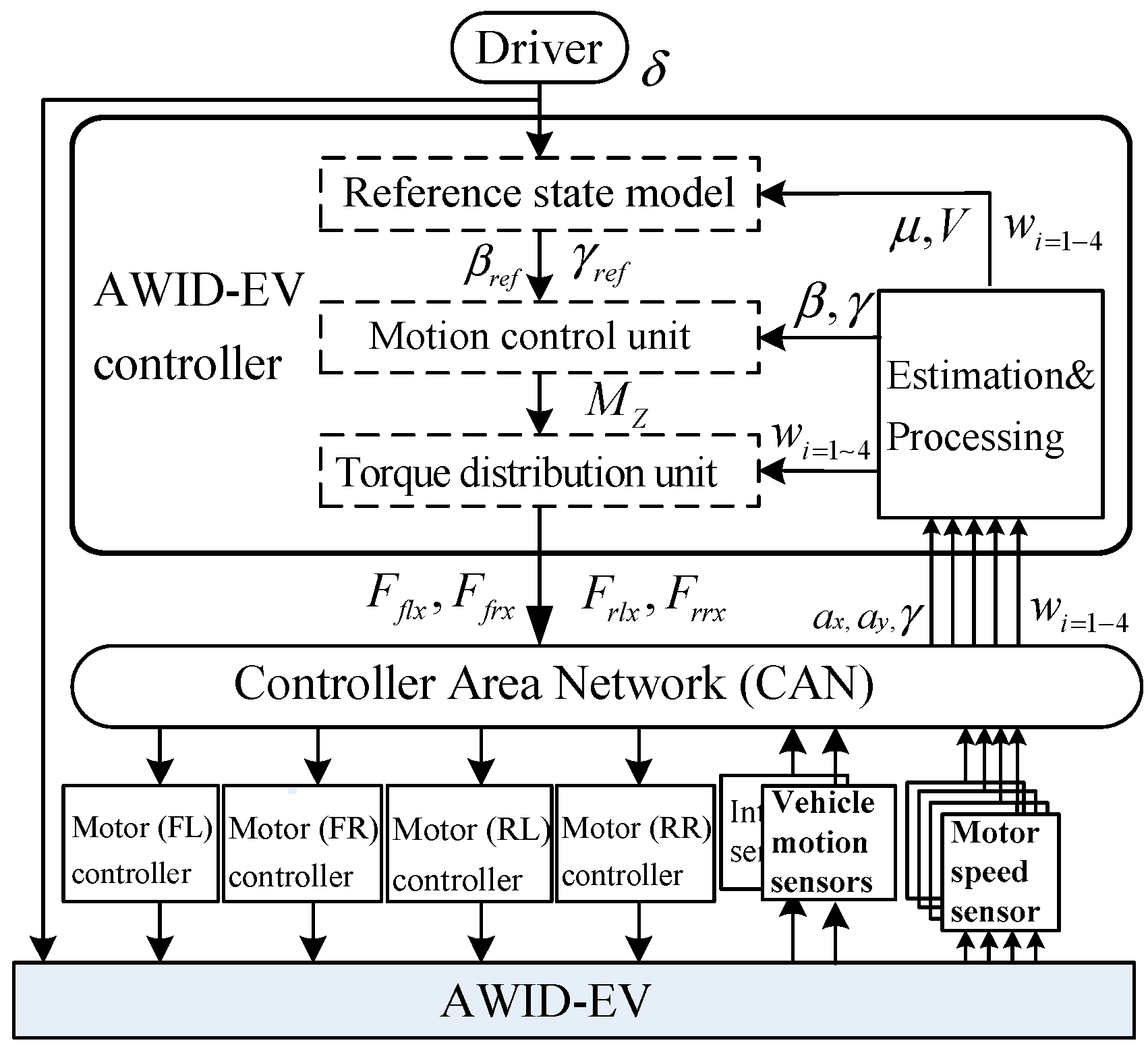
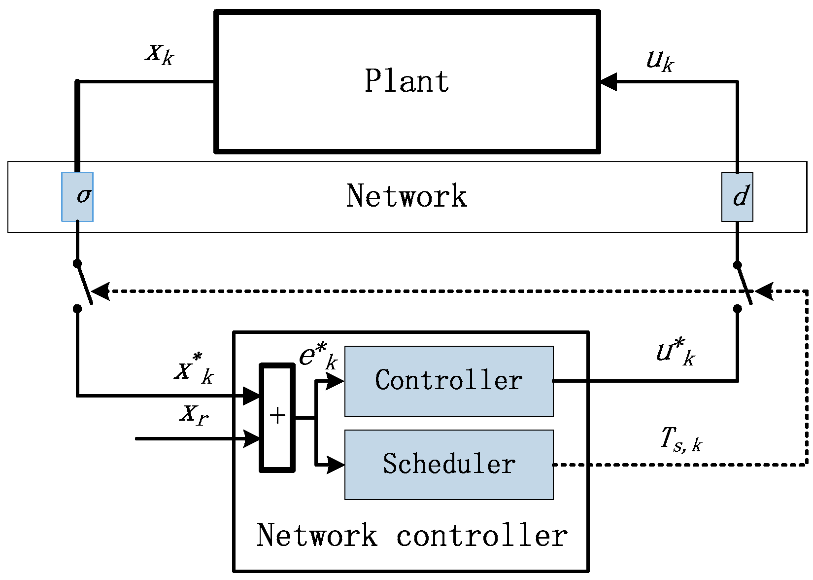
To improve the vehicle lateral motion control, a typical networked control architecture is adopted in this study as shown in Figure 1. The top hierarchy is for the AWID-EV controller, where the DYC based control strategy is implemented. The Second hierarchy is for CAN where real-time data are exchanged between the top hierarchy and the low hierarchy. The low hierarchy is for sensors and actuators.
The DYC aims to keep the vehicle lateral motion states tracking the desired reference states. As shown in Figure 1, the DYC based control strategy in the top hierarchy mainly consists of a reference state model, a motion control unit, a torque distribution unit and an estimation and processing unit. The reference state model is used to yield the desired reference states, which are designed in the following Section 2.2. The estimation and processing unit is used to estimate or calculate the actual vehicle motion states based on the measurements from sensors. The sideslip angle β and the yaw rate γ are adopted as two state variables in the vehicle lateral motion control. Each motor/wheel speed is defined as ωi, and these motor/wheel speed signals are used to road condition estimation for obtaining tire-road friction coefficients (see [26] for details of a road condition estimation method based on motor/wheel speeds). The actual sideslip angle β is usually estimated based on the longitudinal/lateral acceleration information. The actual yaw rate γ and actual motor/wheel speed are usually measured directly by sensors. The motion control unit is used to calculate the control command, which is the research focus of this paper. The torque distribution unit is used to allocate the desired torque to each in-wheel motor. Taking a four-wheel vehicle as an example, in the DYC control system, there are two acceleration sensors, one yaw rate sensor, four motor speed sensors, four motor actuators and the AWID-EV controller, which are connected by CAN. In other words, plentiful real-time data among these control system components are exchanged via a CAN.
2.2. Control-Orient Model of AWID-EVs with DYC
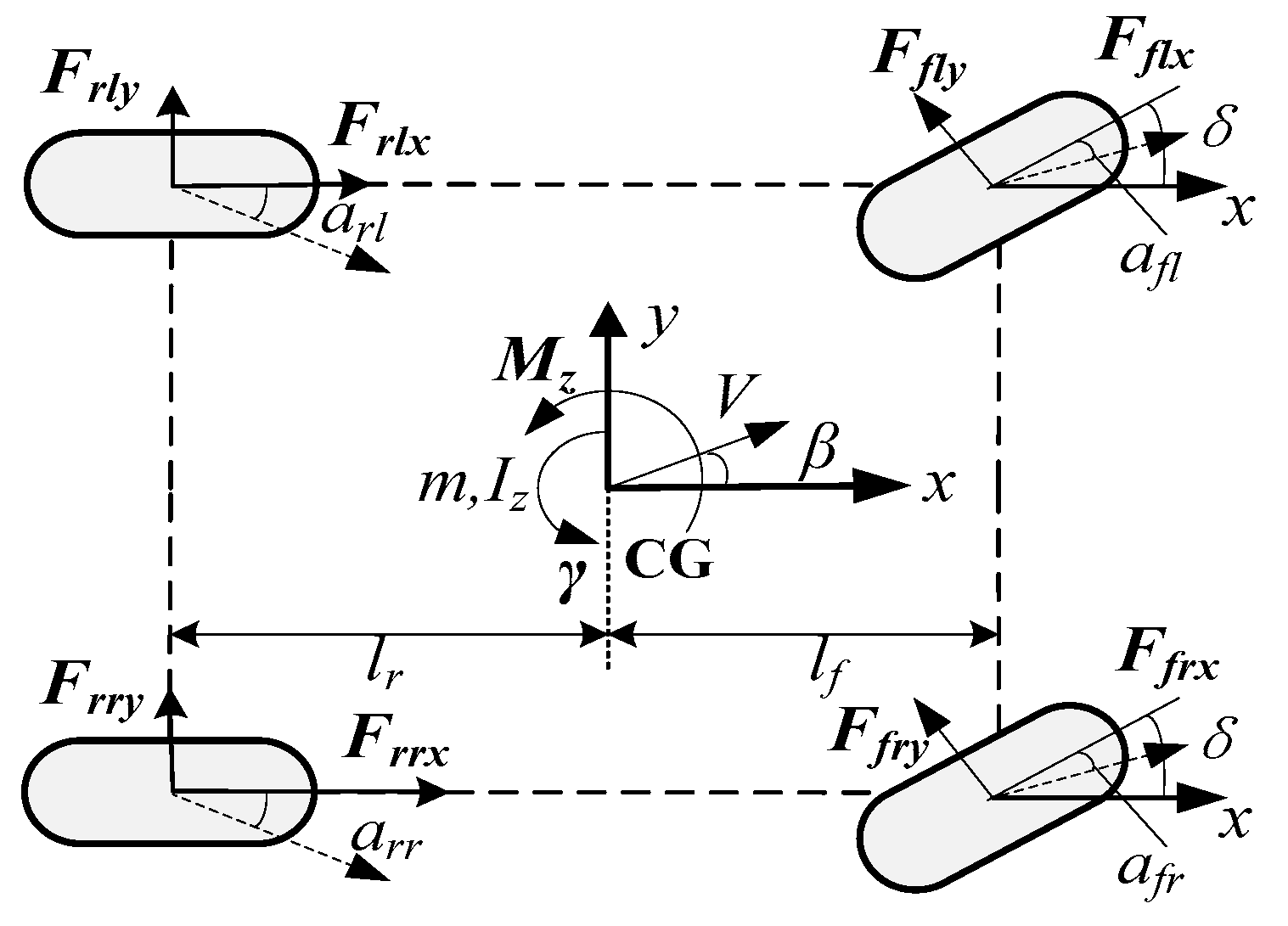
To design a DYC based strategy, a simplified two-degree-of-freedom (2-DOF) vehicle dynamics model with the yaw moment input, which is widely used for controller design [4], is adopted in this study as shown in Figure 2.
With the 2-DOF model, the lateral vehicle dynamics model for DYC can be described as follows:
where
with and denoting cornering stiffness of the front and rear tires, respectively.
To realize the tracking control of the vehicle lateral motion state, a widespread reference state model [3] can be expressed as
where
To improve the vehicle handling performance, a new vector is defined. An augmented system for DYC is described as
where
To design a digital control system for the vehicle lateral motion control, the discrete-time expression of the control-orient model with a fixed sampling period T is derived as follows:
where
2.3. Vehicle Model with CAN-Induced Delays
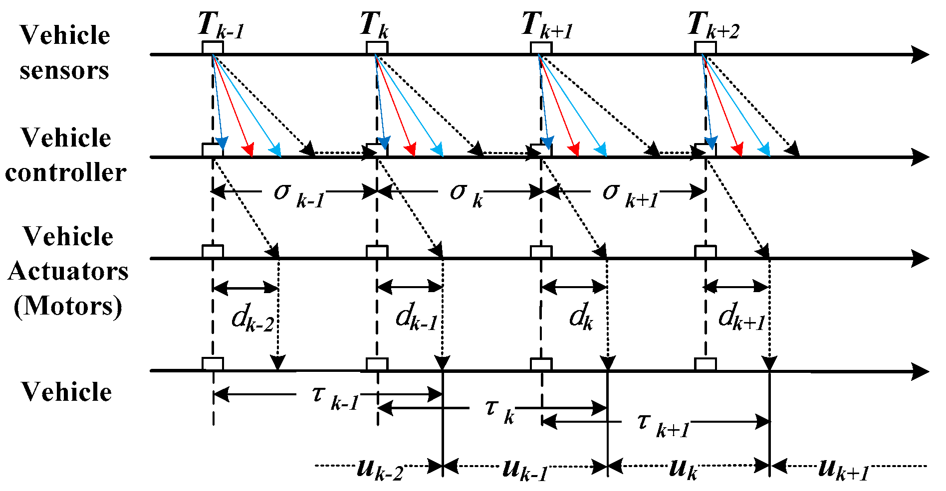
Due to the network-induced delays caused by CAN, the vehicle input uk is implemented with the delay as shown in Figure 3, where denotes the total network-induced delay in the loop consisting of the forward channel and feedback channel.
where stands for the network-induced delay in the feedback channel, and stands for the network-induced delay in the forward channel.
Therefore, a vehicle using CAN is a system with network-induced delays. The control-orient vehicle model for DYC is described as follows
It is assumed that in the networked control system: (1) all sensor nodes and controller nodes operate in time-driven mode and their clocks work synchronously; (2) all motor actuator nodes operate in event-driven mode where a task will be immediately implemented once a message arrives via CAN; (3) commands are grouped into one data frame which is transmitted from the controller node to four motor actuator nodes (that is called broadcast mode in CAN protocol) and each data frame can be transmitted once in every sampling period. With these assumptions, the network-induced delays are described as follows
With the network-induced delay in the loop, the control-orient discrete-time model is rewritten as follows
where
2.4. The Network Utilization of CAN
According to the protocol of CAN, the network utilization of a CAN system [27] can be described with the following expression as:
where
with N being the number of data frames, denoting the period of a message, denoting the worst-case time taken to transmit a message physically on the bus [28], being the number of bytes of payload data (), denoting bit time. is for the standard-format frame or is for the extended-format frame.
3. Control Syntheses
To deal with all the effects of the network-induced delays and the network congestion, a co-design based scheme combining a period-dependent LQR controller and a fuzzy-based dynamic period scheduler is designed in this study shown in Figure 4, where the controller is used to generate the control commands and the scheduler is used to online adjust the sampling period of the control system.
3.1. Period-Dependent LQR Controller Design
Firstly, without considering the effects of network-induced delays, a discrete-time period-dependent LQR controller is designed to improve the vehicle lateral motion with the discrete-time vehicle model shown in Equation (4).
A performance index is defined to minimize the tracking error and the control input as follows:
where and are two positive definite weighting matrices, which are selected to balance between vehicle handling performance and safety.
The period-dependent state-feedback optimal gain K(T) can be solved with the lqrd(, , Q, R, T) command in MATLAB. Therefore, the control law can be yielded as .
Secondly, considering the effects of network-induced delays and substituting the control law into the control-orient discrete-time model, the close-loop system is derived as follows
Defining a vector , an augmented expression can be written as follows
where
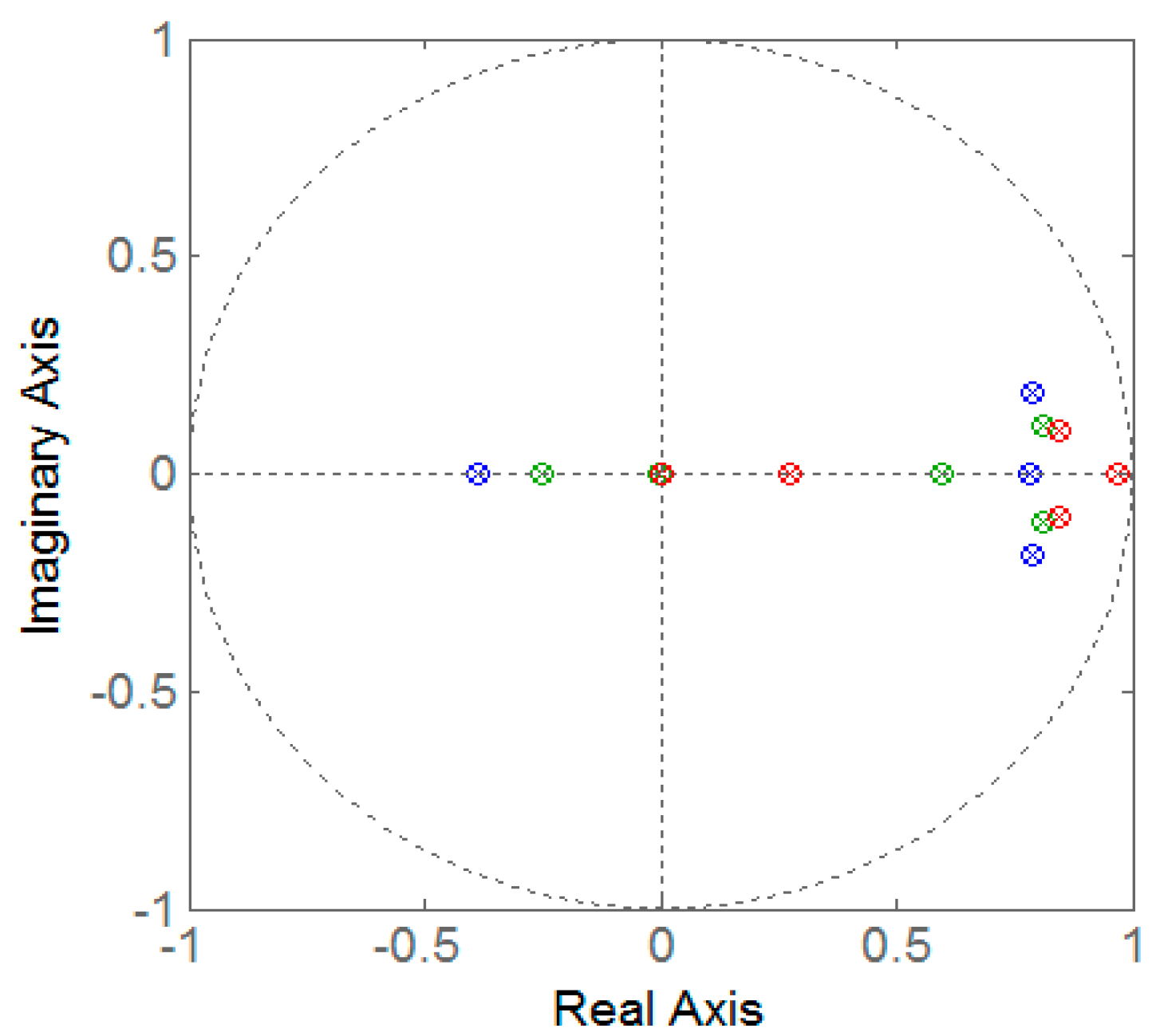
Theorem 1.
With Lyapunov based stability criterion, the close-loop system shown in Equation (12) is asymptotically stable if all eigenvalues of the system matrix locate within the unit circle on Complex plane as shown in Figure 5.
With the Theorem 1, we find that the longer the sampling period, the worse the control performance of the system. On the other hand, with the expression of network utilization in Equation (9), the shorter the sampling period, the higher the network utilization. Therefore, it is difficult to simultaneously obtain both the good control performance and the low network utilization when using a fixed sampling period. To deal with this design conflict, a dynamic sampling period scheduler is designed in the following section.
3.2. Fuzzy-Based Dynamic Sampling Period Scheduler Design
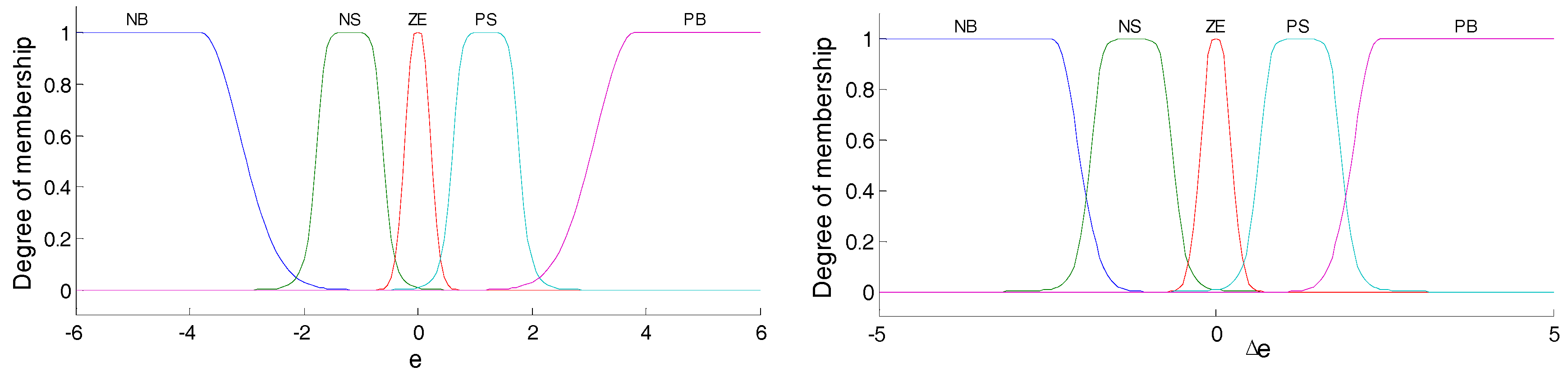
Considering that it is difficult to obtain the mathematic model between the control performance of the system and the sampling period, as shown in Figure 6, a fuzzy-based dynamic sampling period scheduler is designed. The tracking response error and are considered as two input variables, whereas the sampling period is used as the output variable. Moreover, to provide enough rule coverage, five fuzzy sets are used for both the two input variables. Meanwhile, four sets are used for the output variable as follows:
The fuzzy linguistic terms are described in Table 1.
The scaling factors SF1 and SF2 are used to map the crisp values of the input and output variables to their fuzzified values, which are tuned at the design stage by trial. The membership functions are used for the fuzzification of the input variables, which are shown in Figure 7. The rule base is defined in Table 2. The fuzzy unit employs the Takaki-Sugeno Fuzzy Inference System (FIS).
4. Simulation Results
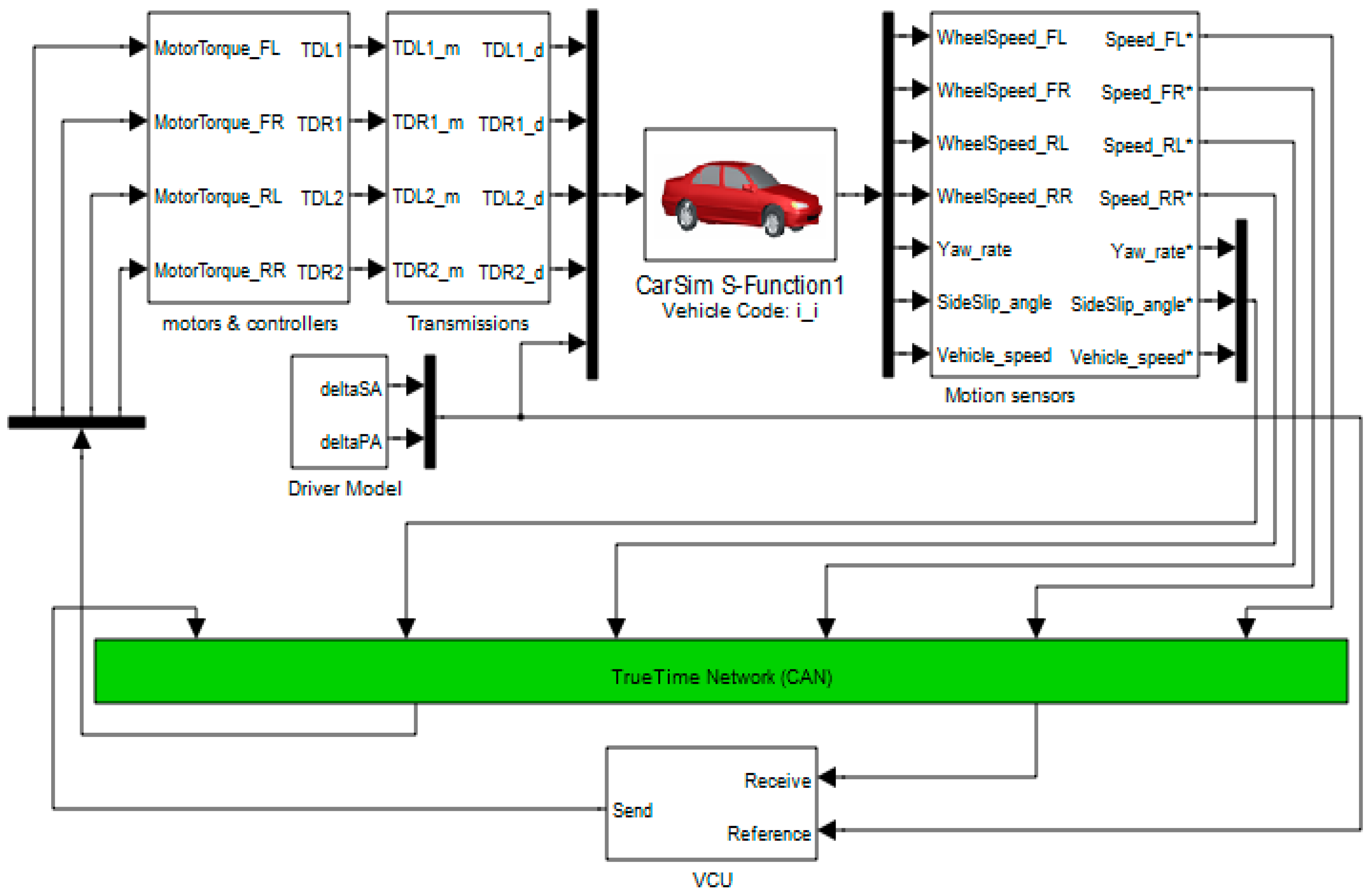
To assess the effectiveness of the proposed scheme, simulations are conducted in Matlab/Simulink® with a full-vehicle model constructed by CarSim® and a CAN-network model from TrueTime toolbox. The simulation diagram is shown in Figure 8. Vehicle parameters used in these simulations are obtained with the help of a prototype of 4WID-EV from BAIC® (Beijing, China), and some main parameters are given in Table 3.
The VCU model is composed of a controller and a scheduler as shown in Figure 4. The controller is used to implement the DYC based control strategy which consists of a motion control unit and a torque distribution unit as shown in Figure 1. In this study, the designed period-dependent LQR controller is adopted in the motion control unit and a static same torque allocation logic is employed in the torque distribution unit as in [3]. Moreover, the designed fuzzy-based dynamic period scheduler is used to adjust the sampling period of the control system.
The CAN model is designed based on a TrueTime Network block in TrueTime toolbox, which is a powerful Matlab-based network simulation toolbox [29] and can effectively emulate real-time networked control system within the automotive industry [30]. The network type of CSMA/AMP (CAN) and the data rate of 250 kbits/s are chosen in the TrueTime Network block. To test the network load, the minimum frame size is chosen as 157 bits, which is the length of an extended CAN data frame with the worst-case padding bits according to CAN2.0B protocol.
The driver model gives steering wheel angle and accelerator pedal angle inputs for each driving maneuver. Two typical maneuvers are considered here: a double-step steering maneuver and a double-lane-changing steering maneuver, which are commonly used in vehicle handling performance test.
The in-wheel motors and controllers and transmissions are modeled to receive and implement control commands and scheduling commands sent by the VCU model via the CAN network and to apply torque to each wheel. Motion sensors are modeled to transfer the measurements of vehicle motion states from the vehicle to the CAN.
For comparison, several fixed-period LQR controllers that consider the effects of the sampling periods are also designed for the motion control unit. The sampling periods are chosen as [10 ms 15 ms 20 ms 25 ms 35 ms].
In these simulations, the vehicle speed is chosen as 100 km/h and the tire-road friction coefficient is chosen as 0.85. The LQR controllers are designed using the following weighting matrices
Q = [300,0,0; 0,600,0; 0,0,300000], R = 0.000001
The period-dependent gains can be obtained as follows:
K(10 ms) = [20080 42180 −488900] K(15 ms) = [20020 40690 −462350]
K(20 ms) = [19950 39280 −437530] K(25 ms) = [19890 37930 −414310]
K(35 ms) = [19760 35410 −372230]
4.1. Double-Step Steering Maneuver
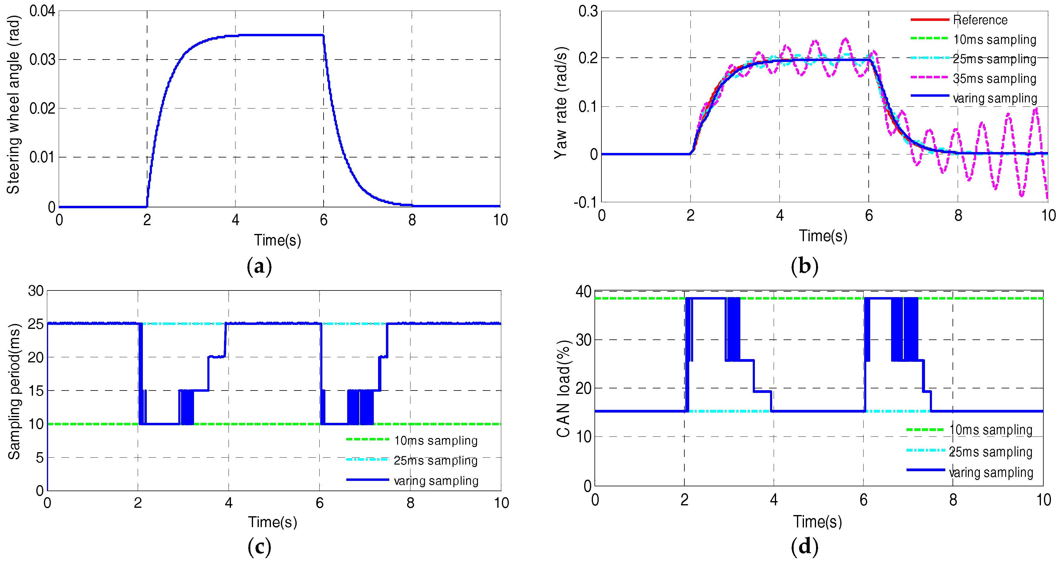
Figure 9 shows the steering wheel angle input and the simulation results in the double-step steering maneuver. With the communication of CAN, both the controller with the fixed period of 10 ms and the proposed scheme yield satisfactory results of the yaw rate tracking response, whereas the controller with the fixed period of 25 ms causes slight oscillations in the steering process but can still ensure that the tracing error asymptotically converges to zero, however the controller with the fixed period of 35 ms leads to obvious oscillations in the steering process and even when the wheel steering angle is returned to zero in straight-line driving state, which degrades the vehicle lateral motion performance and even may make the vehicle unstable. The results show that, for these controllers with fixed periods, the vehicle handling performance will become worse as the sampling period becomes longer.
Moreover, while ensuring the stability of the system, the proposed scheme yields dynamic sampling period as shown in Figure 9c, where the sampling period of the closed-loop system is changed between 25 ms and 10ms by the designed fuzzy-based dynamic period scheduler. Correspondingly, the network load results are shown in Figure 9d, where the proposed scheme leads to high network utilization of around 39% in the transient phase of the double-step steering process but to low network utilization of around 16% in the steady phase of the driving process, whereas the controller with the fixed period of 10 ms always leads to high network utilization of around 39% even if in the steady phase. These results show that the proposed scheme can reduce the network load by as much as 58% in the steady phase of driving process compared to the controller with the fixed period of 10 ms while ensuring the vehicle system stability.
The comparison results show that in the double-step steering maneuver the proposed scheme can not only ensure the asymptotical stability of the vehicle handling control but also obviously decline the network congestion.
4.2. Double-Lane-Changing Steering Maneuver
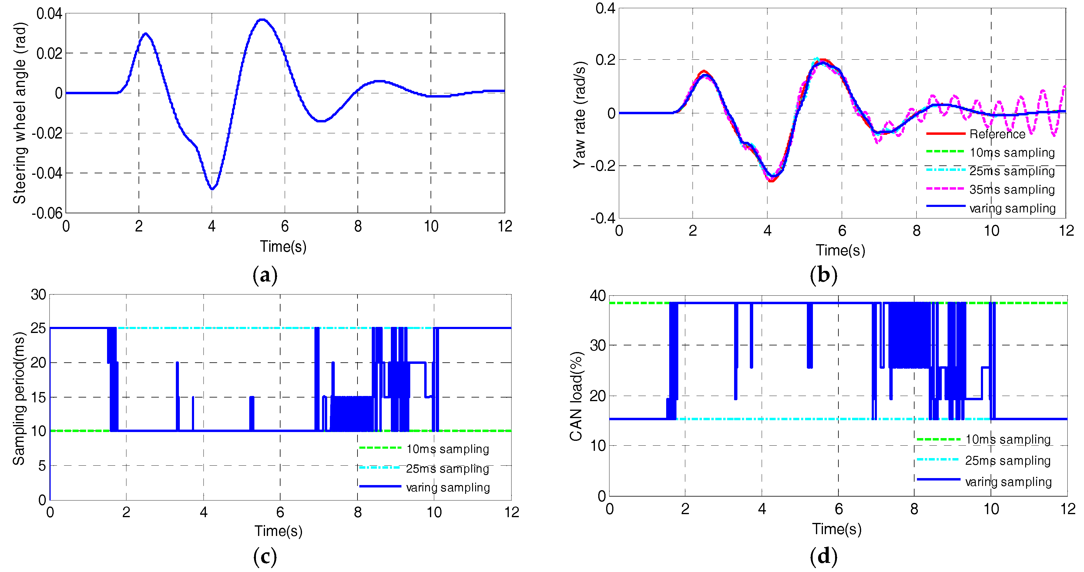
Figure 10 shows the steering wheel angle input and the simulation results in the double-lane-changing steering maneuver. The comparative results in Figure 10 are almost the same as the ones of the previous maneuvers. With the CAN, both the proposed scheme and the controller with the fixed period of 10 ms perform well, whereas the controller with the fixed period of 25 ms causes slight oscillations but still ensure the system instability, however the controller with the fixed period of 35 ms makes obvious oscillations in the latter part from 7th s to 12th s, which may leads to the vehicle instability.
Furthermore, while guaranteeing the stability of the vehicle lateral motion control, the proposed scheme obtains dynamic sampling period in the double-lane-changing steering maneuver as shown in Figure 10c, where the sampling period of the closed-loop system varies between 25 ms and 10 ms, which is adjusted by the designed fuzzy-based dynamic period scheduler. Meanwhile, as shown in Figure 10d, compared with the controller with the fixed period of 10 ms, the proposed scheme can obviously reduce the network load by around 58% in the steady phase of driving process, e.g., from 10th s to 12th s.
The comparison results show that in the double-lane-changing steering maneuver the proposed scheme can not only ensure the stability of the vehicle handling control but also effectively decline the network congestion as well.
5. Test Results
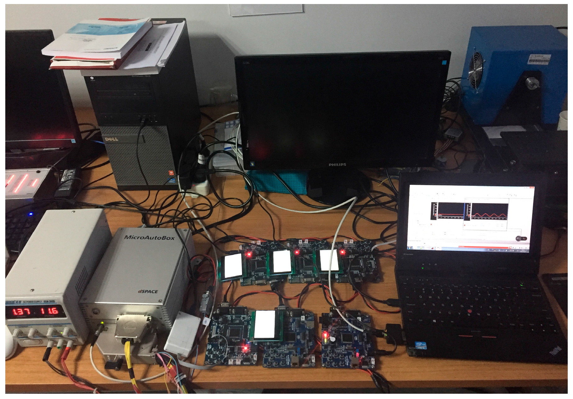
To experimentally validate the proposed scheme, a HIL (Hardware-In-the-Loop) test bench is set up consisting of a dSPACE MicroAutoBox plant simulator linked via a CAN with 6 Freescale based ECUs (4 ECUs for motor controllers, 1 ECU for VCU and 1 ECU for the vehicle motion sensor node) as shown in Figure 11. A PC with CANking software is also linked to the CAN through a Kvaser CAN connector to observe the statistical network load.
The vehicle system model can be loaded from Matlab into the MicroAutoBox, which represents a real-time system based on a DS1401 board. These embedded ECUs are implemented on Freescale based 16-bit MC9S12XF512 units. In details, 4 motor controllers receive scheduling commands and control commands from the CAN and send motor speed measurements to the CAN, respectively. The VCU receives the measurements from the CAN and the sensors directly linked by wire, e.g., the steering wheel angle sensor, and sends the scheduling commands and control commands to the CAN. The vehicle motion sensor node sends the measurements such as the yaw rate and the sideslip angle and receives the scheduling commands from the CAN. All the network nodes run with the varying sampling period sent by the VCU. The baudrate of the CAN is chosen as 250 kbits/s.
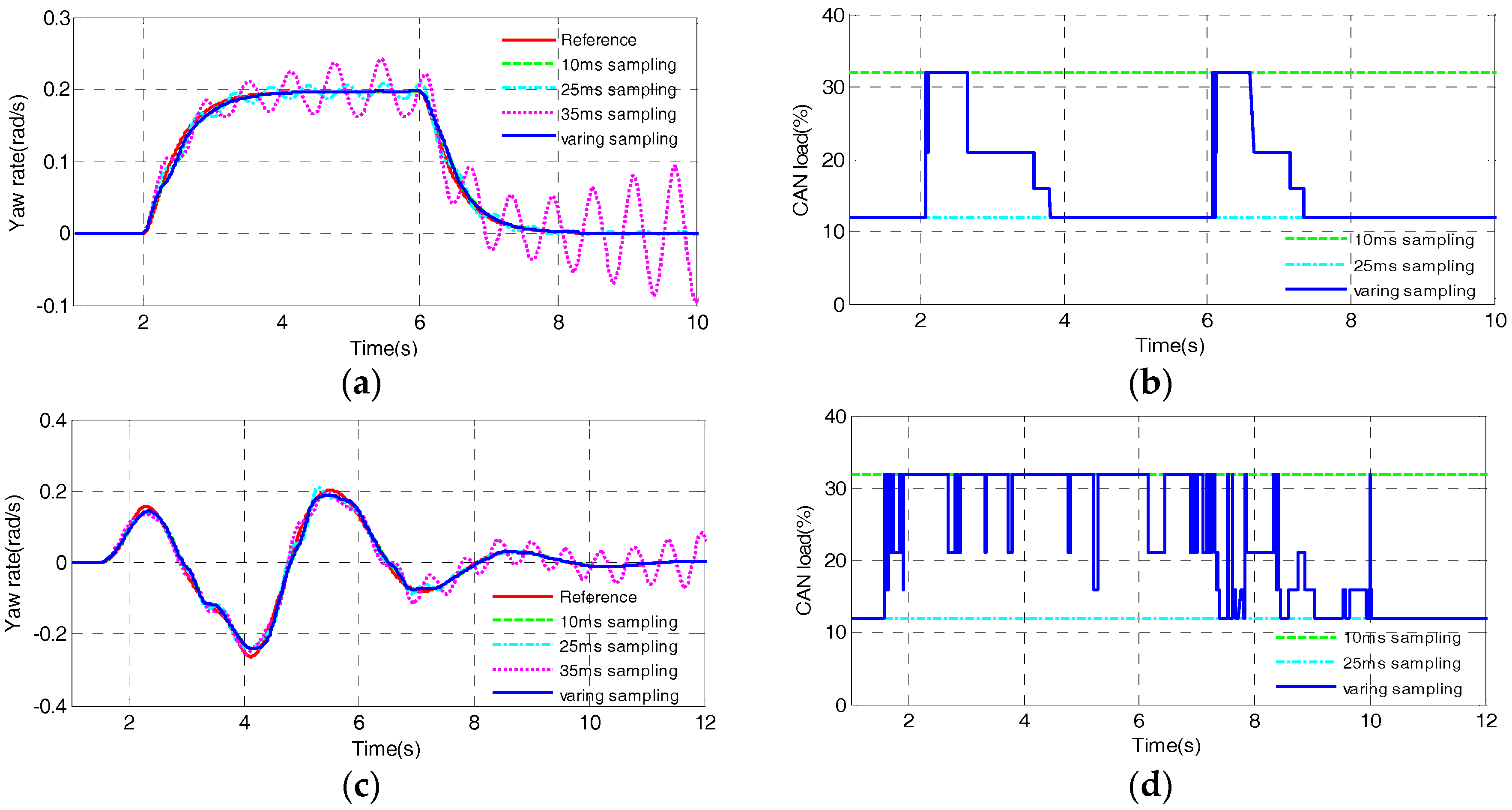
The results of the tests are shown in Figure 12, where the yaw rate response and the network load results in two steering maneuvers are similar to the ones in previous simulations, which proves that the proposed scheme can effectively ensure the vehicle stability and obviously reduce the network utilization in the real-time network environment. It is worth noting that the network loads in the real CAN are slightly smaller than the ones in the simulation. The reason is that the worst-case padding bits in CAN frames are considered in the simulation, which results in the slightly conservative results.
6. Conclusions
In this paper, the network congestion, besides the network-induced delays, is explicitly taken into account in the control system design for the lateral motion control of AWID-EVs. A co-design based scheme combining a period-dependent LQR controller and a dynamic sampling period scheduler is designed. The results in the simulation and HIL experiment tests show that the proposed methodology can not only effectively ensure the vehicle lateral motion control stability in spite of the network-induced delays but also obviously reduce the network congestion.
In addition, the results of the network utilization statistics in the vehicle lateral motion control indicate that the network utilization would result in severe network congestion and make the system integration difficult. Therefore, additional attention should be paid to the network congestion in the control system design for AWID-EVs.
Acknowledgments
This work was supported in the part by the National Key R&D Program of China (under Grant No. 2017YFB0103801) and the Research Fund of BIT (Grant No. 3030012261701).
Author Contributions
Wanke Cao and Helin Liu conceived the original ideas. Wanke Cao, Helin Liu and Zhiyin Liu performed the simulations and HIL tests. Wanke Cao, Yuhua Chang and Zhiyin Liu wrote the manuscript. Cheng Lin and Antoni Szumanowski directed the overall project. All authors discussed the results and comments on the manuscript.
Conflicts of Interest
The authors declare no conflict of interest.
References
- Gorbe, P.; Magyar, A.; Hangos, K.M. Reduction of power losses with smart grids fueled with renewable sources and applying EV batteries. J. Clean. Prod. 2012, 34, 125–137. [Google Scholar] [CrossRef]
- Zhu, X.; Zhang, H.; Fang, Z. Speed synchronization control for integrated automotive motor–transmission powertrain system with random delays. Mech. Syst. Signal Process. 2015, 64–65, 46–57. [Google Scholar] [CrossRef]
- Shuai, Z.; Zhang, H.; Wang, J.; Li, J.; Ouyang, M. Combined AFS and DYC Control of Four Wheel Independent Drive Electric Vehicles over CAN network with Time-Varying Delays. IEEE Trans. Veh. Technol. 2014, 63, 591–602. [Google Scholar] [CrossRef]
- Shuai, Z.; Zhang, H.; Wang, J.; Li, J.; Ouyang, M. Lateral motion control for four-wheel-independent-drive electric vehicles using optimal torque allocation and dynamic message priority scheduling. Control Eng. Prac. 2014, 24, 55–66. [Google Scholar] [CrossRef]
- He, H.; Peng, J.; Xiong, R.; Fan, H. An Acceleration Slip Regulation Strategy for Four-Wheel Drive Electric Vehicles Based on Sliding Mode Control. Energies 2014, 7, 3748–3763. [Google Scholar] [CrossRef]
- Park, J.; Jeong, H.; Jang, I.G.; Hwang, S.-H. Torque Distribution Algorithm for an Independently Driven Electric Vehicle Using a Fuzzy Control Method. Energies 2015, 8, 8537–8561. [Google Scholar] [CrossRef]
- Wang, R.; Hu, C.; Wang, Z.; Yan, F.; Chen, N. Integrated optimal dynamics control of 4WD4WS electric ground vehicle with tire-road frictional coefficient estimation. Mech. Syst. Signal Process. 2015, 60–61, 727–741. [Google Scholar] [CrossRef]
- Sakai, S.-I.; Sado, H.; Hori, Y. Motion Control in an Electric Vehicle with Four Independently Driven In-Wheel Motors. IEEE/ASME Trans. Mechatron. 1999, 4, 9–16. [Google Scholar] [CrossRef]
- Hori, Y.; Toyoda, Y.; Tsuruoka, Y. Traction Control of Electric Vehicle: Basic Experimental Results Using the Test EV “UOT Electric March”. IEEE Trans. Ind. Appl. 1998, 34, 1131–1138. [Google Scholar] [CrossRef]
- Hu, C.; Wang, R.; Yan, F.; Chen, N. Output Constraint Control on Path Following of Four-Wheel Independently Actuated Autonomous Ground Vehicles. IEEE Trans. Veh. Technol. 2016, 65, 4033–4043. [Google Scholar] [CrossRef]
- Song, P.; Zong, C.-F.; Tomizuka, M. A terminal sliding mode based torque distribution control for an individual-wheel-drive vehicle. J. Zhejiang Univ.-Sci. A (Appl. Phys. Eng.) 2014, 15, 681–693. [Google Scholar] [CrossRef]
- Hori, Y. Furture Vehicle Driven by Electricity and Control-Research on Four-Wheel-Motored UOT Electric March II. IEEE Trans. Ind. Electron. 2004, 51, 954–962. [Google Scholar] [CrossRef]
- Wang, R.; Wang, J. Fault-Tolerant Control With Active Fault Diagnosis for Four-Wheel Independently Driven Electric Ground Vehicles. IEEE Trans. Veh. Technol. 2011, 60, 4276–4287. [Google Scholar] [CrossRef]
- Zhu, X.; Zhang, H.; Wang, J.; Fang, Z. Robust Lateral Motion Control of Electric Ground Vehicles with Random Network-Induced Delays. IEEE Trans. Veh. Technol. 2015, 64, 4985–4995. [Google Scholar] [CrossRef]
- Wang, Y.; Fujimoto, H.; Hara, S. Torque Distribution-Based Rang Extension Control System for longitudinal motion of Electric Vehicles by LTI Modeling with Generalized Frequency Variable. IEEE/ASME Trans. Mechatron. 2016, 21, 443–452. [Google Scholar]
- Yang, X.; Wang, Z.; Peng, W. Coordinated control of AFS and DYC for vehicle handing and stability based on optimal guaranteed cost theory. Veh. Syst. Dyn. 2009, 47, 58–78. [Google Scholar] [CrossRef]
- Goodarzi, A.; Esmailzadeh, E. Design of a VDC System for All-Wheel-Independent Drive Vehicles. IEEE/ASME Trans. Mechatron. 2007, 12, 632–639. [Google Scholar] [CrossRef]
- Chen, B.-C.; Kuo, C.-C. Electronic Stability Control for Electric Vehicle with Four In-Wheel Motors. Int. J. Autom. Technol. 2014, 15, 573–580. [Google Scholar] [CrossRef]
- Novellis, L.D.; Sorniotti, A.; Gruber, P. Wheel Torque Distribution Criteria for Electric Vehicles with Torque-Vectoring Differentials. IEEE Trans. Veh. Technol. 2014, 63, 1593–1602. [Google Scholar] [CrossRef]
- Ando, N.; Fujimoto, H. Yaw-rate Control for Electric Vehicle with Active Front/Rear Steering and Driving/Braking Force Distribution of Rear Wheels. In Proceedings of the 11th IEEE International Workshop on Advanced Motion Control, Nagaoka, Japan, 21–24 March 2010. [Google Scholar]
- Li, D.; Du, S.; Yu, F. Integrated vehicle chassis control based on direct yaw moment, active steering and active stabiliser. Veh. Syst. Dyn. 2008, 46, 341–351. [Google Scholar] [CrossRef]
- Wanke, C.; Zhihao, Y.; Cheng, L. The dynamic studies of dual-motor independent drive electric vehicle with network control. In Proceedings of the IEEE Transportation Electrification Conference and Expo, Beijing, China, 31 August–3 September 2014. [Google Scholar]
- Qin, G.; Zou, J. H∞ Control of Four Wheel Independent Drive Electric Vehicles with Random Time-Varying Delays. Math. Probl. Eng. 2015, 2015, 245493. [Google Scholar] [CrossRef]
- Cao, W.; Liu, Z.; Chang, Y.; Szumanowski, A. Direct Yaw-Moment Control of All-Wheel-Independent-Drive Electric Vehicles with Network-Induced Delays through Parameter-Dependent Fuzzy SMC Approach. Math. Probl. Eng. 2017, 2017, 5170492. [Google Scholar] [CrossRef]
- de Novellis, L.; Sorniotti, A.; Gruber, P.; Orus, J.; Fortun, J.-M.R.; Theunissen, J. Direct yaw moment control actuated through electric drivetrains and friction brakes: Theoretical design and experimental assessment. Mechatronics 2015, 26, 1–15. [Google Scholar] [CrossRef] [Green Version]
- Yin, D.; Oh, S.; Hori, Y. A Novel Traction Control for EV Based on Maximum Transmissible Torque Estimation. IEEE Trans. Ind. Electron. 2009, 56, 2086–2094. [Google Scholar]
- Buttazzo, G.C. Rate Monotonic vs. EDF: Judgment Day. Real-Time Syst. 2005, 29, 5–26. [Google Scholar] [CrossRef] [Green Version]
- Leen, G.; Heffernan, D. TTCAN: A new time-triggered controller are network. Microprocess. Microsyst. 2002, 26, 77–94. [Google Scholar] [CrossRef]
- Cervin, A.; Henriksson, D.; Lincoln, B.; Eker, J.; Arzen, K.-E. How Does Control Timing Affect Performance? Analysis and Simulation of Timing Using Jitterbug and True Time. IEEE Control Syst. Mag. 2003, 23, 16–30. [Google Scholar] [CrossRef]
- Caruntu, C.F.; Lazar, M.; Gielen, R.H.; Bosch, P.P.J.V.D.; Cairano, S.D. Lyapunov based predictive control of vehicle drivetrains over CAN. Control Eng. Prac. 2013, 21, 1884–1898. [Google Scholar] [CrossRef]
Figure 1.
Networked control architecture for DYC.

Figure 2.
Simplified 2-DOF vehicle dynamics model for DYC. CG is the center of vehicle gravity; m is the vehicle mass; is the vehicle yaw inertia; V is the vehicle speed; denotes the yaw moment generated by the distribution of the longitudinal forces among all drive wheels; and respectively stand for the distances from the front and rear axles to CG; , , and denotes longitude tire forces of front and rear wheels, respectively; , , and are lateral tire forces of front and rear wheels, respectively; , , and are slip angles of front and rear wheels , respectively; δ denotes the steering angle of front wheels.

Figure 3.
Network-induced delays in the loop of AWID-EVs.

Figure 4.
The scheme based on the co-design of scheduling and control.

Figure 5.
Eigenvalue locus of the system matrix on Complex plane.

Figure 6.
Fuzzy-logic sampling period scheduler.
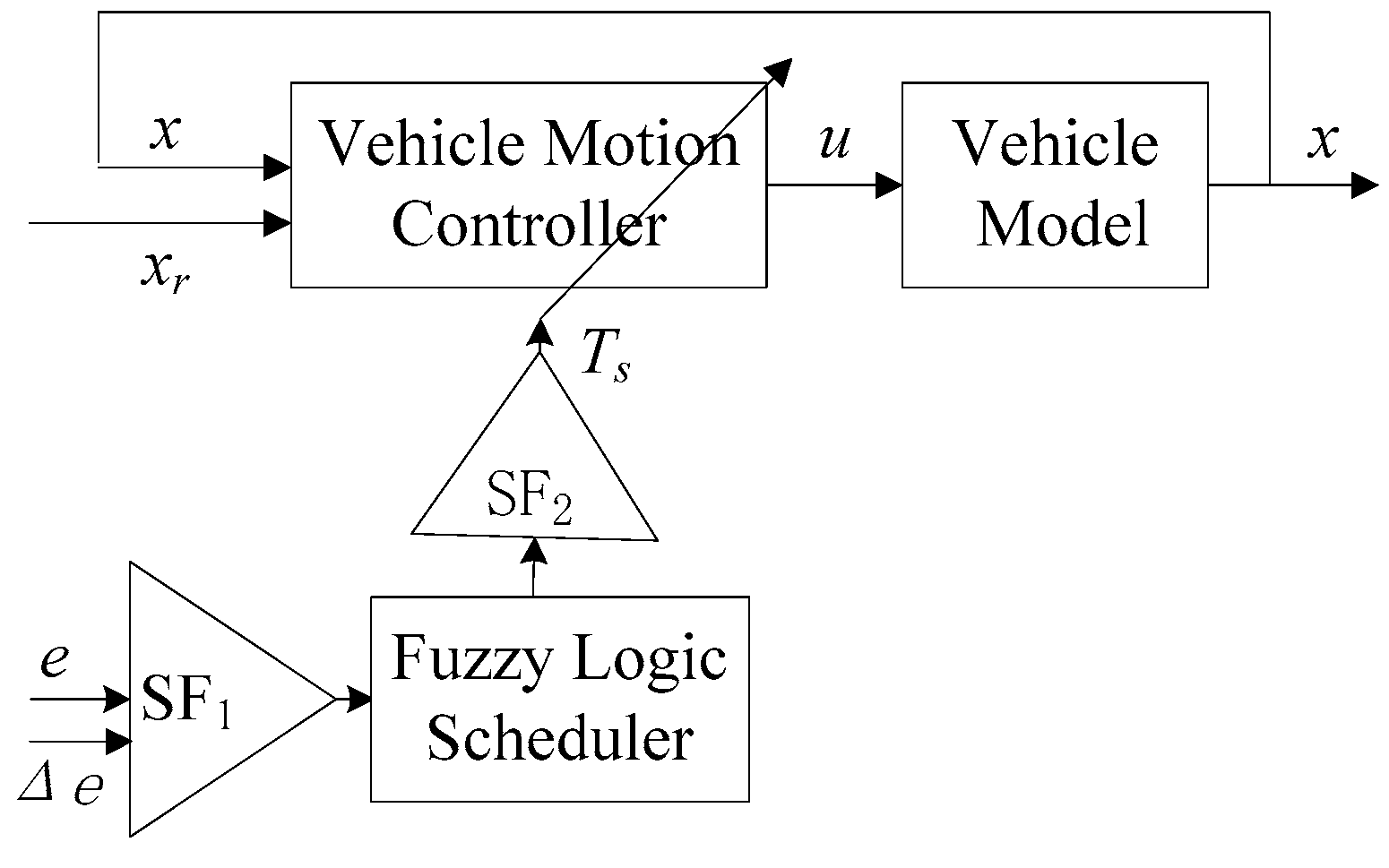
Figure 7.
Membership functions of input variables.

Figure 8.
Simulation diagram in Simulink with model blocks from CarSim and TrueTime toolbox.

Figure 9.
Simulation input and results in the double-step steering process: (a) The steering wheel angle input; (b) The yaw rate responses; (c) The sampling periods; (d) The CAN load statistics.
Figure 9.
Simulation input and results in the double-step steering process: (a) The steering wheel angle input; (b) The yaw rate responses; (c) The sampling periods; (d) The CAN load statistics.

Figure 10.
Simulation input and results in the double-lane-changing steering process: (a) The steering wheel angle input; (b) The yaw rate responses; (c) The sampling periods; (d) The CAN load statistics.
Figure 10.
Simulation input and results in the double-lane-changing steering process: (a) The steering wheel angle input; (b) The yaw rate responses; (c) The sampling periods; (d) The CAN load statistics.

Figure 11.
Hardware-in-loop (HIL) test bench.

Figure 12.
HIL test results in two steering maneuvers: (a) The yaw rate responses in the double-step steering process; (b) The CAN load statistics in the double-step steering process; (c) The yaw rate responses in the double-lane-changing steering process; (d) The CAN load statistics in the double-lane-changing steering process.


Table 1.
Fuzzy linguistic terms.
| Symbol | Descriptions |
|---|---|
| NB | Negative Big |
| NS | Negative Small |
| ZE | Zero |
| PS | Positive Small |
| PB | Positive Big |
Table 2.
Rule base.
| Δe | ||||||
|---|---|---|---|---|---|---|
| NB | NS | ZE | PS | PB | ||
| e | NB | T1 | T1 | T2 | T1 | T1 |
| NS | T1 | T2 | T3 | T2 | T1 | |
| ZE | T2 | T3 | T4 | T3 | T2 | |
| PS | T1 | T2 | T3 | T2 | T1 | |
| PB | T1 | T1 | T2 | T1 | T1 | |
Table 3.
Main vehicle parameters.
| Parameter | Description | Quantity |
|---|---|---|
| m | Vehicle mass | 1350 kg |
| IZ | Yaw moment of inertia | 1975 kg·m2 |
| lf | Front semi-wheelbase | 1.085 m |
| lr | Rear semi-wheelbase | 1.386 m |
| cf | Cornering stiffness of front tires | 58,000 N/rad |
| cr | Cornering stiffness of Rear tires | 60,000 N/rad |
© 2017 by the authors. Licensee MDPI, Basel, Switzerland. This article is an open access article distributed under the terms and conditions of the Creative Commons Attribution (CC BY) license (http://creativecommons.org/licenses/by/4.0/).
Share and Cite
MDPI and ACS Style
Cao, W.; Liu, H.; Lin, C.; Chang, Y.; Liu, Z.; Szumanowski, A. Co-Design Based Lateral Motion Control of All-Wheel-Independent-Drive Electric Vehicles with Network Congestion. Energies 2017, 10, 1641. https://doi.org/10.3390/en10101641
AMA Style
Cao W, Liu H, Lin C, Chang Y, Liu Z, Szumanowski A. Co-Design Based Lateral Motion Control of All-Wheel-Independent-Drive Electric Vehicles with Network Congestion. Energies. 2017; 10(10):1641. https://doi.org/10.3390/en10101641
Chicago/Turabian StyleCao, Wanke, Helin Liu, Cheng Lin, Yuhua Chang, Zhiyin Liu, and Antoni Szumanowski. 2017. "Co-Design Based Lateral Motion Control of All-Wheel-Independent-Drive Electric Vehicles with Network Congestion" Energies 10, no. 10: 1641. https://doi.org/10.3390/en10101641
Note that from the first issue of 2016, this journal uses article numbers instead of page numbers. See further details here.