Article

Evaluation of Electrical Tree Degradation in Cross-Linked Polyethylene Cable Using Weibull Process of Propagation Time

1
Metropolitan Transportation Research Center, Korea Railroad Research Institute, Uiwang 16105, Korea
2
ICT Fusion Green Energy Center, Wonkwang University, Iksan 54538, Korea
*
Author to whom correspondence should be addressed.
Energies 2017, 10(11), 1789; https://doi.org/10.3390/en10111789
Submission received: 25 September 2017 / Revised: 31 October 2017 / Accepted: 3 November 2017 / Published: 7 November 2017
(This article belongs to the Section F: Electrical Engineering)

Abstract

:
The main purpose of this paper is to evaluate electrical tree degradation for cross-linked polyethylene (XLPE) cable insulation for three difference models. In order to show the distribution characteristics using phase resolved partial discharge (PD), we acquire data by using a PD detecting system. These acquired data presented four 2D distributions such as phase angle-average discharge distribution, pulse magnitude-pulse number distribution, phase angle-pulse number distribution, and phase angle-maximum discharge derived from the distribution of PD. From the analysis of these distributions, each of the tree models are proved to hold its unique characteristics and the results were then applied as basic specific qualities. In order to evaluate the progresses of an electrical tree, we proposed methods using parameters by means of Weibull distribution to the time of tree propagation. We measured the time of tree propagation for 16 specimens of each artificial tree models from initiation stage, middle stage, and final stage respectively, using these breakdown data, we estimated the shape parameter, scale parameter, and mean time to failure. It is possible to analyze the difference in lifetime between the initial stage, the middle stage, and the final stage, and could be used to predict the lifetime of an XLPE cable from these results.

1. Introduction

Maintenance technology for diagnosing electric power equipment has shifted from time-based maintenance to both condition-based and reliability-centered maintenance in Korea. Among various methods of implementing condition-based diagnosis, partial discharge (PD) diagnosis method is most widely used because it is easy to derive parameters for insulation diagnosis. This is thanks to sufficient information on the insulation condition of the electric power equipment that is contained in signals arising from the occurrence of PD in the power equipment [1,2]. Construction of a number of electric railroads incorporating high-speed rail has recently taken place, and a lot of railway sections involving long tunnels have also been constructed in Korea. Whereas insulated cables are rarely utilized in the general sections of electric railroads due to the overhead catenary lines being used there, the minimalized construction of insulated cables in tunnel sections is operated from the perspective of the cross-sectional area of a tunnel on the grounds of construction costs. So, feeder wires are installed inside tunnels as insulated cables on overhead catenary lines. The condition diagnosis and degradation evaluation of the insulated cables installed in tunnels emerge as important factors.
Electrical treeing in cable insulation is a pre-breakdown phenomenon for insulation failure and the main factor in the insulation degradation of solid insulators. Therefore, discerning any electrical tree and investigation its propagation status is undoubtedly most crucial because it is directly related to the lifespan of the equipment [3,4,5,6,7,8,9,10,11].
To determine the propagation of electrical trees, this paper came up with three types of simulated electrical tree specimens and presented a method of revealing it by estimating the shape and scale parameters using the Weibull distribution [12,13,14,15,16,17,18,19]. As a method of using Weibull distribution analysis, partial discharge sizes were employed to uncover the propagation of electrical trees by estimating the shape and scale parameters step by step and analyze their change characteristics. In addition, by using 16 specimens for each model, the failure time in the event of any tree propagation was measured and presented. The failure times were then identified and categorized into three relevant tree propagation stages, thereby estimating the shape parameters, the scale parameters and the mean time to failures (MTTF) at each stage.

2. Test Specimens and Experimental Setup

2.1. Artificial Electrical Tree Model

The specimens for the artificial electrical tree discharge were secured by cutting some Cross-linked Polyethylene (XLPE) insulating material portions off a Korea power distribution cable with rating voltage 13.2 kV, three different types of tree models were made as shown in Figure 1.
Each specimen was made by inserting a needle into the relevant insulating material after heating it to 100 °C in order to inhibit the occurrence of any nonessential electric discharge due to the complete adherence of the interface between the needle and the insulating material during the needle insertion. The made specimens were tested in the insulation oil condition in order to prevent any surface discharge that could possibly occur on surface and outside.

2.2. Experimental Method and Data Processing

2.2.1. Partial Discharge Measurement

The experimental apparatus for the occurrence of PD and the obtainment of relevant data consists of a PD-free transformer, a PD pulse acquisition, storage, a display system and a microscope for observing electrical trees as shown in Figure 2. The apparatus is designed in such a way so that voltage application, data acquisition and data processing are all possible with it. Partial discharge pulses were detected using a PD detector (Biddle Instruments, Dallas, TX, USA), and the data was derived from the Φ-q-n distribution. Data format acquired from PD detector is 8 × 512 matrix which the phase angle of one cycle is divided into 64 sections and pulse count is calculated by dividing the discharge magnitude into 64 sections based on the maximum discharge magnitude. PD statistical distributions are calculated and investigated from these data format.

2.2.2. Observation of Tree Propagation

In order to check the occurrence and growth of tree, an optical microscope (Olympus, Tokyo, Japan) was installed above test specimens immersed in the oil tank as shown in Figure 3b. The microscope was connected to the computer through Charge Coupled Device (CCD) camera as shown in Figure 3a. The growth image of tree was able to be observed and recorded on computer.

2.2.3. Tree Growth and Degradation Stage

In the case of the needle-plane structure used in this experiment, PD inception voltage (PDIV) was measured about 16 kV. The PDIV was judged by PD pulse magnitude, but the background noise was 2 pC in test laboratory, PDIV was set when PD pulse was above 5 pC. In this paper, applied voltage was set to13.2 kV during tree growth, and tree could be made to progress rapidly according to the voltage after PD was occurred.
It is important thing to investigate properties of tree propagation for three artificial tree models because it could find out the correlation with the lifetime depending on sources of defect the tree occurred. We assume that the degradation stage of the tree was divided into initiation, middle and final respectively for 0.6~0.9 mm, 1.5~1.8 mm and above 2.4 mm based on the tree growth length.

3. Experimental Results

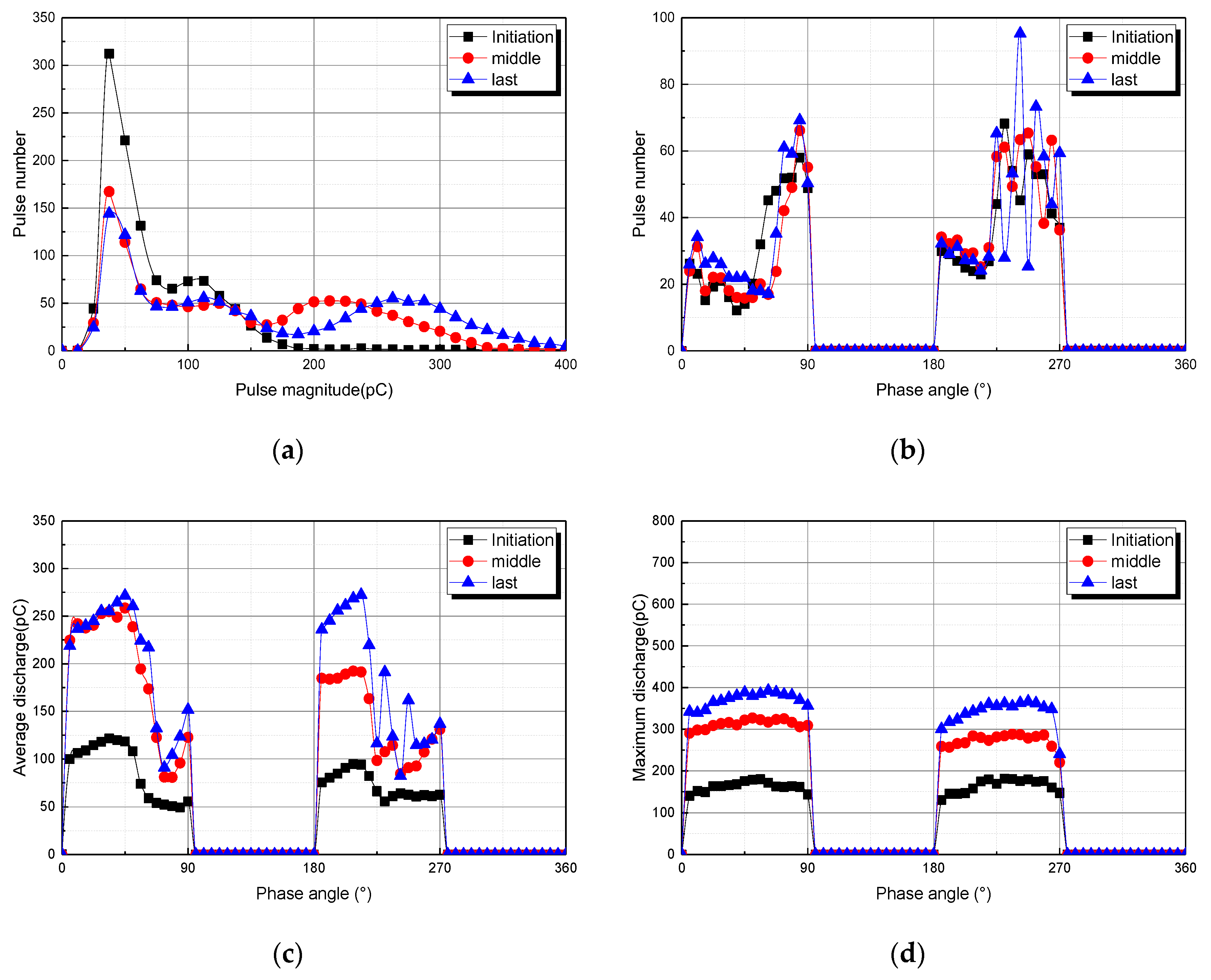
3.1. Partial Discharge Distributions for Tree Model 1

Figure 4 show the partial discharge distributions during the tree propagation in tree model 1. In the case of model 1, as shown in Figure 3, if AC voltage is applied, the breakdown voltage is lower (the voltage at which corona occurs is lower) in general when the needle in the needle-to-plane electrode is negative than when it is positive, and the tree growth is fast when the needle is positive, therefore, insulation failure may occur much more easily when the needle electrode has entered the positive half cycle. For these particular reasons, it can be concluded that any discharge pulse occurring is larger in the positive half cycle.
The distribution of pulse repetition rate of PD tends to decrease as the electrical tree propagation proceeds from the initiation stage towards the final stage, whereas in the cases of the PD—related distributions, Hqn(Φ) and Hqmax(Φ), their values tend to increase as the electrical tree propagation proceeds towards the final stage of its propagation. This reveals that the quantity of electric discharge is a more important factor than the frequency of discharge occurrence in understanding the characteristics of both the insulation degradation and failure.

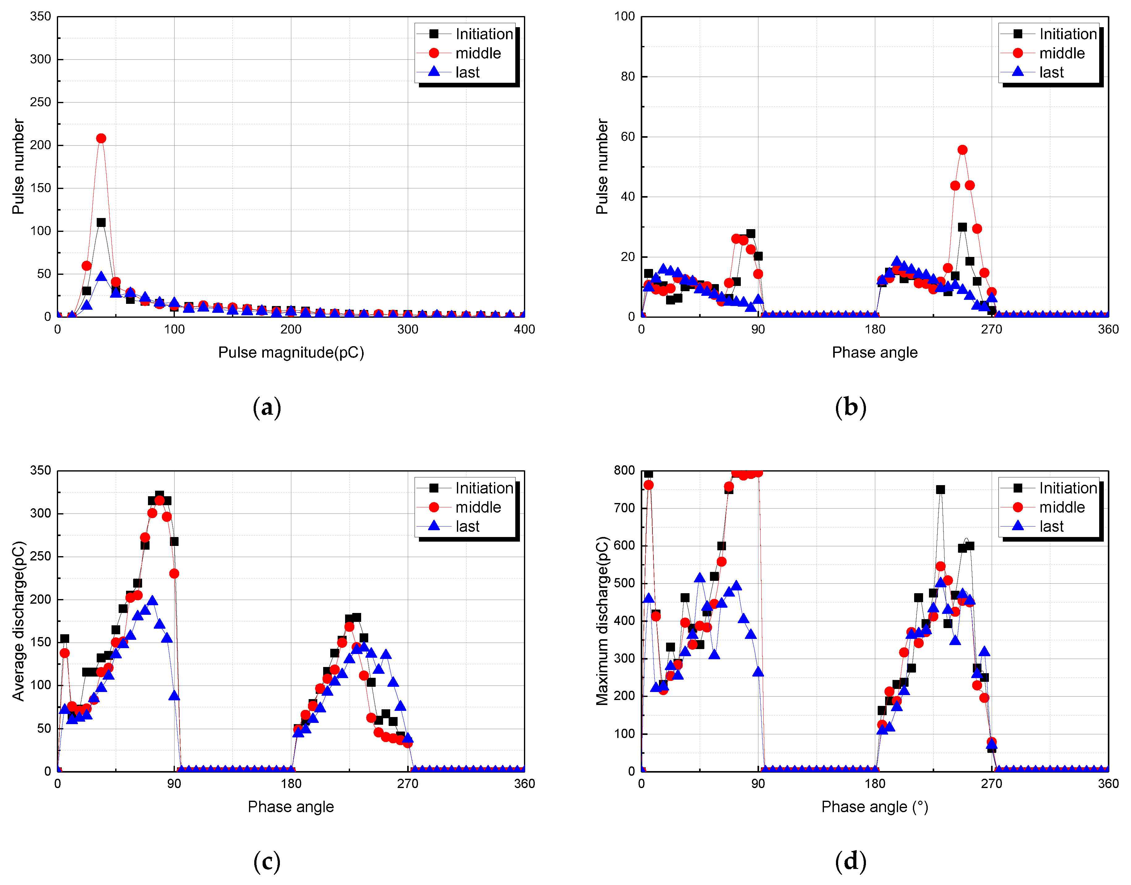
3.2. Partial Discharge Distributions for Tree Model 2

Figure 5a–d show electric discharge distributions during the tree propagation in model 2. Much like in the case of model 1, the repetition rate of PD is more frequent in the positive half cycle than in the negative half cycle in model 2. PD magnitude has shown to be greater in the positive half cycle than in the negative half cycle. Both the mean and largest PD magnitude are greater in the positive half cycle. This seems to be the result of the existence of a void in the needle tip in model 2, unlike in the case of model 1. This phenomenon also shown the same characteristics even when there was a metallic foreign material in model 3. Model 2 shows similar characteristics in the PD pulse repetition rate, its growth is clearly classified into the initiation stage, the middle stage, and the final stage in terms of the PD magnitude. In addition, as the tree propagation proceeds further towards the last stage, the data on the discharge pulse above 300 pC shows the greater PD pulse repetition rate.

3.3. Partial Discharge Distributions for Tree Model 3

The electric discharge size characteristically does not grow when the electrical tree propagates. Figure 6 shows PD distributions during the tree propagation in Tree Model 3. Many electric discharges occurred in the negative half cycle, thus displaying a high frequency of its occurrence, whereas the positive half cycle showed definitely high values in electric discharge size in Tree Model 3. The PD magnitude was discovered to be greatest in Model 3 and seems to be a phenomenon appearing as a result of an electric field being concentrated near the metallic foreign material. However, both the PD repetition rate and magnitude are characteristically shown to be greater during the initiation and middle stages rather than during the final stage.
These are considered due to the influence of the metallic foreign material. More specifically, they are considered to be a phenomena appearing not only due to the complicated occurrence of the electric discharge from the needle tip, electric discharge together with a metallic foreign material, and electric discharge starting from the metallic foreign material but also due to the reinforcement of an electric field nearby under the influence of the metallic foreign material.

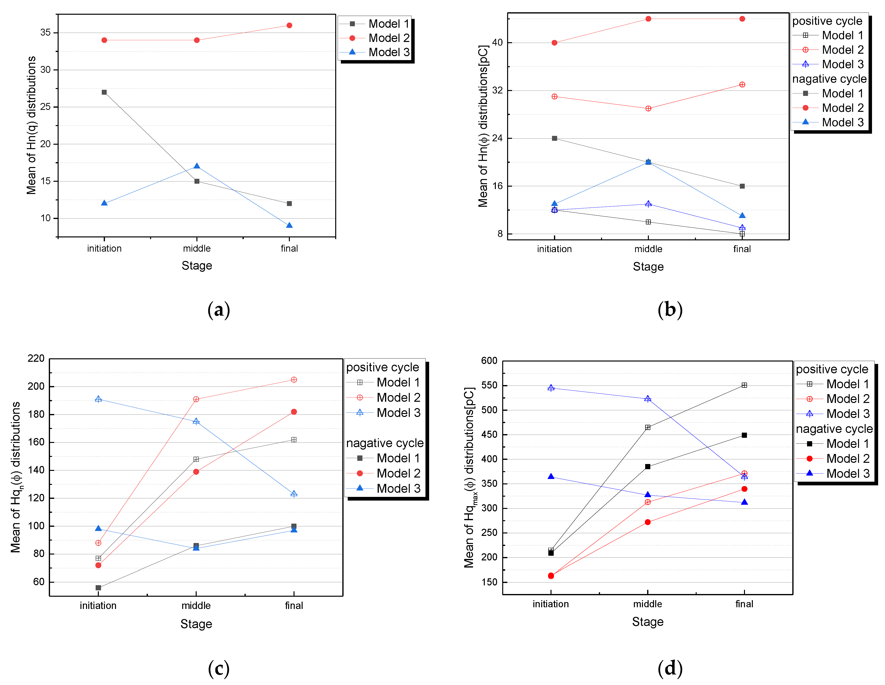
3.4. Tendeny of Statistical Distributions of PD According to Tree Propagation

Figure 7a–d show the variation of mean value of statistical distributions of PD in order to investigate PD tendency according to tree propagation stage for each artificial tree models.
The distribution of Hn(q) and Hn(Φ) show the tendency that the variation rate of distribution decreases and the distribution of Hqn(Φ) and Hqmax(Φ) increase as growing tree propagation at positive and negative cycles in case of model 1. For the case of model 2 as shown in Figure 7b, variation ratio tends to increasing as growing the tree propagation in every statistical distributions, but it is similar variation rate during middle to final stage for Hn(Φ) distribution. In case of model 3, we get the tendency that variation ratio of mean value for Hn(Φ) distribution is increasing from initiation toward middle stage, but rather decreasing as growing progress of final stage. In addition, the tendency of variation for Hqn(Φ) and Hqmax(Φ) distributions gradually shows decrease as progress to final stage, and variation rate at the time to the final stage is larger than at the time from initiation to the middle stage.

3.5. Evaluation of the Degradation Degree of XLPE Cable Using Weibull Analysis

3.5.1. Weibull Analysis

The degradation degree of the electrical trees is an important evaluation element because it is directly related to the lifetime of the cable. Several methods to classify PD sources or insulation diagnosis were proposed like fuzzy theory, artificial neural network (ANN), fractal model, statistical methods, and backpropagation. In previous papers, we proposed methods to identify partial discharge sources and diagnosis using ANN, adaptive network based fuzzy inference system and principle component analysis linear discriminant system [16,17,18,19]. In order to evaluate the degradation degree of the electrical trees more accurately, this paper has processed the electrical tree propagation time by means of the Weibull distribution.
Weibull analysis offers a mathematical approach for the tree propagation time analysis. The cumulative Weibull function is shown in Equation (1):
F ( t ; α , β ) = 1 exp [ ( t α ) β ]
Here, t is tree propagation time, α is the scale parameter, and β is the shape parameter. Scale parameter and shape parameter are derived by using least square estimation method.

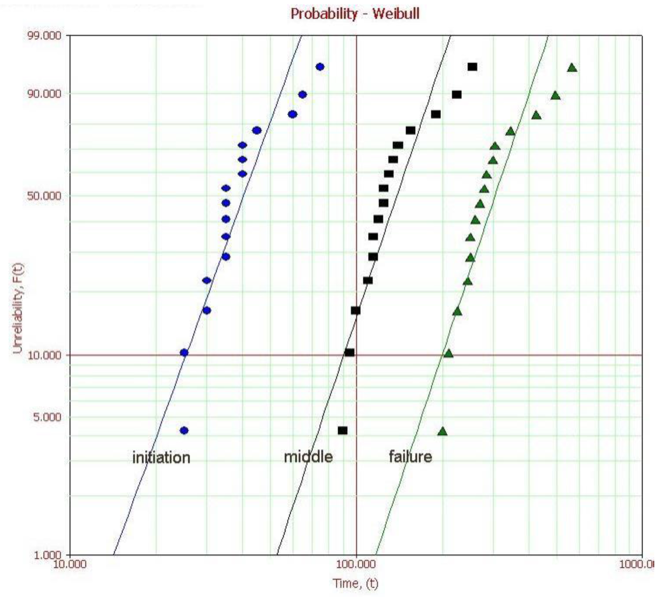
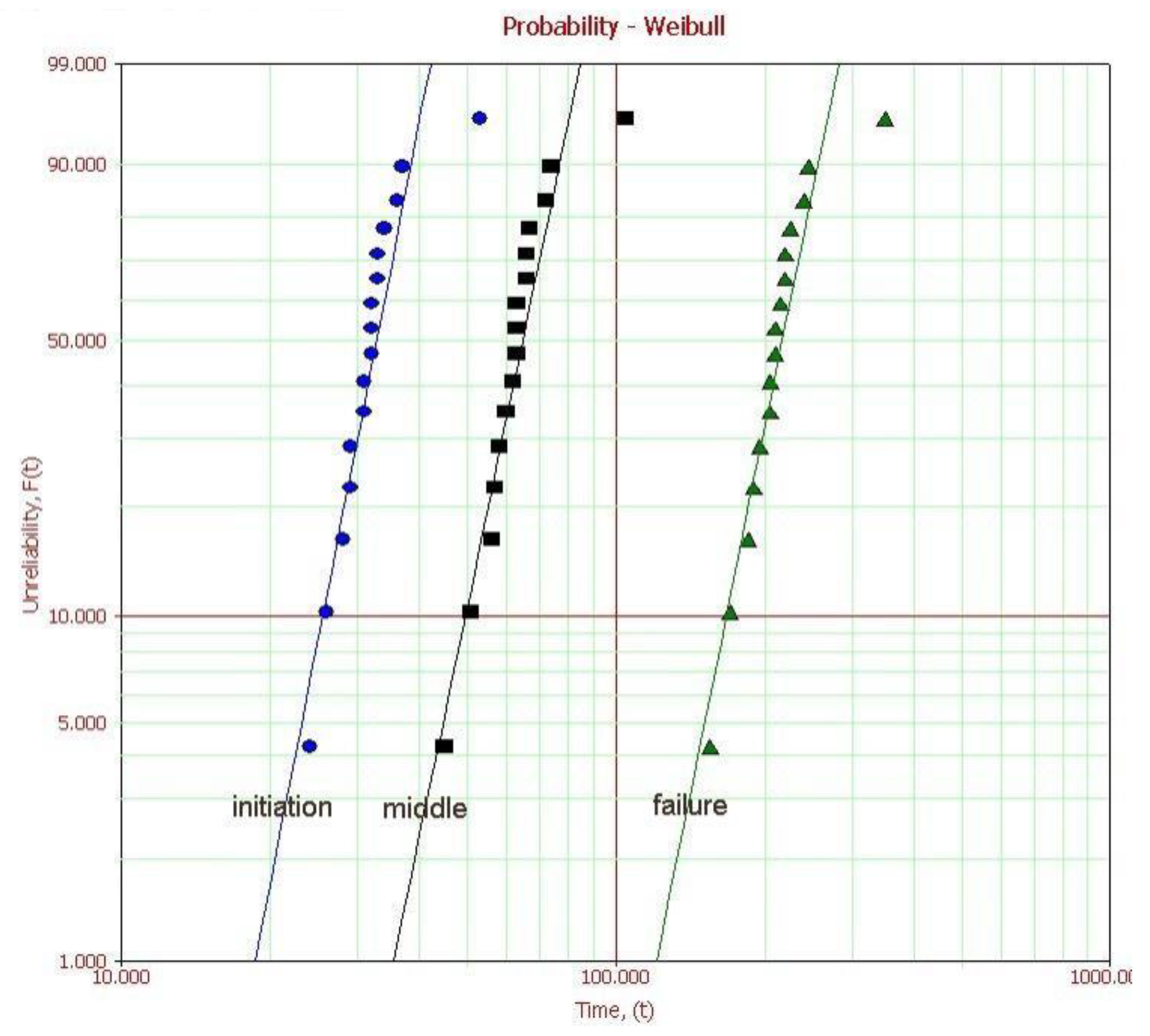
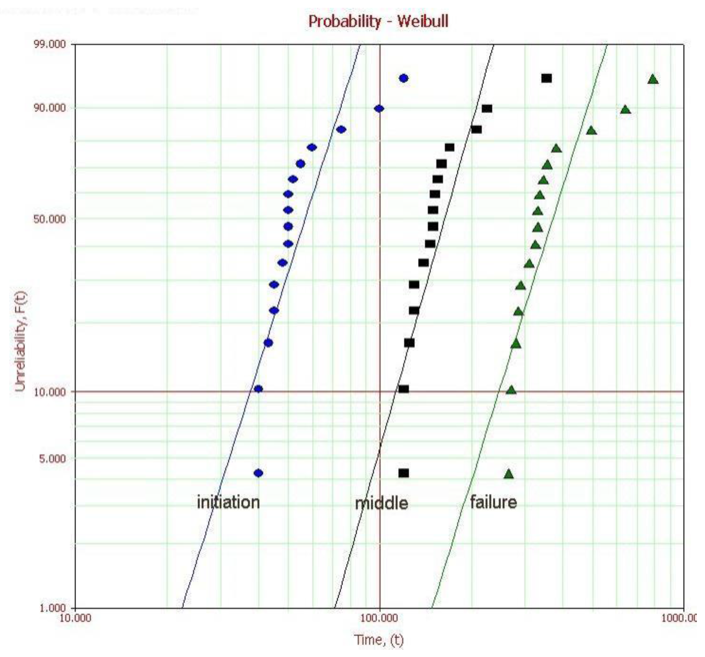
3.5.2. Examination of the Electrical Tree Propagation Time

Figure 8 shows the failure times during the electrical tree propagation for 16 specimens in each model. The tree propagation time was discovered to be shortest when there was any void in the needle tip (Model 2), whereas the tree propagation was slowest when there was metallic foreign material (Model 3). In Model 3, it was confirmed that although the electric tree propagation tended to be fast when there was any kind of metallic foreign material during the initiation stage, its propagation from the metallic foreign material until the occurrence of insulation failure proceeded so slowly that the insulation failure occurred later than in any other case.
Each failure time was measured after classifying the electrical tree propagation stages into three stages in order to estimate the parameters and the mean lifetime at each stage through the tree occurrence testing of electrical tree model specimens. The propagation stages of each electrical tree were restricted into the time of its 30% growth as the initiation stage, the time of its 60% growth as the middle stage, and the time of insulation failure as the failure stage (i.e., final stage).
Table 1 reveals the growth times for each electrical tree propagation stage of Model 1. The estimated Weibull distributions and parameters are as shown in Figure 9 and Table 2 respectively.
Figure 8 displays the results of applying failure time data based on the classification of the propagation stages in Electrical Tree Model 1 to the Weibull function. It means that some parts of the measurement data have different forms of distributions, and the shape and scale parameters for each population must be estimated by applying the data to the five-parameter Weibull function. What we can confirm through these measurement results is that three of the 16 trees show different propagation aspects. In general, the propagation of bush-type trees proceeds slowly. Three measurement data represented the propagation of bush-type trees, and the remaining data showed a mixed form of both branch and bush types.
Table 2 displays the shape and scale parameters for each tree propagation stage of Electrical Tree Model 1. All the shape parameters for Population 1 were estimated to have a value of 1 or higher, this means that the tree propagation proceeded in the form of their wear-out failure due to their degradation.
The time difference between the tree propagation stages of the scale parameters for the data on different tree propagation forms, i.e., mutually different populations, was 96 min between the initiation and middle stages and 147 min between the middle and final stages in Population 1, whereas it was 142 min between the initiation and middle stages and 283 min between the middle and final stages in Population 2. The mean lifetime was 96 min between the initiation and middle stages and 165 min between the middle and final stages.
Table 3 displays the time of each tree propagation stage for each specimen in Electrical Tree Model 2. Figure 10 reveals the results from applying the failure time data based on the classification of the tree propagation stages in Model 2 to the Weibull function. One of the measured specimens in Model 2 shows a different form of tree propagation in comparison with the other specimens. In general, at least three pieces of data are required for analyzing the Weibull function. Thus, it is necessary to use the two-parameter estimation method, not the five-parameter estimation method in the case of Model 2.
By using the two-parameter estimation method, the shape parameters were estimated to be 7.5, 7.03, and 7.64 according to the relevant time, the scale parameters were estimated to be 24, 68, and 226 min, and MTTF to be 32, 64, and 212 min.
In model 2, the tree propagation proceeds very fast during the initiation stage but the tree propagation speed is similar to those from other models after the middle stage, this is considered to be because the tree propagates fast at an early stage due to the influence of the void at the end tip of Model 2, but shows a general tree propagation aspect later. However, even if the tree propagation characteristics of Model 2 show similar aspects, what is important is that the time to failure in Model 2 is much shorter in comparison with the other models, this is vital information for understanding the lifetime of the electrical tree according to each defect.
Table 4 is the respective values of the shape parameters, scale parameters, and MTTF in Model 2. The difference in the mean lifetime between the initiation and middle stages was 32 min, and that between the middle and final stages was calculated to be 148 min. When compared with Model 1, the tree propagation time between the initiation and middle stages was shown to be shorter than that in Model 1, however the tree propagation time between the middle and final stages is similar to that of Population 1.
Table 5 displays the failure time data on each tree propagation stage in Electrical Tree Model 3, and Figure 11 shows the results from applying the failure time data based on the classification of the tree propagation stages in Model 3 to the Weibull function. Like in the case of the specimens of Model 1, some of the measurement specimens of Model 3 also reveal different tree propagation aspects in comparison with the other specimens. The shape and scale parameters for each group were estimated by applying the five-parameter estimation method.
Table 6 shows the shape parameters, the scale parameters and the MTTF in Model 3, which were respectively estimated from the measured failure times. The time difference between the tree propagation stages in Population 1 was 100 min between the initiation and middle stages and 206 min between the middle and final stages, whereas the time difference between tree propagation stages in Population 2 was 195 min between the initiation and middle stages and 206 min between the middle and final stages. It can be confirmed from the parameter estimation results in Population 2 that if a bush-type tree propagates during the initiation stage, its propagation is therefore very slow and that the tree propagates much more slowly in Model 3 containing needle-like foreign materials.

4. Discussion

When fully analyzing the failure types according to the relevant time, it can be confirmed that the failure rate increases according to the relevant time in each of the three models. In other words, all the shape parameters have a value of 1 or higher, it can be seen from this that all the three models show a wear-out failure. A curve with this form of an increasing failure rate (IFR) is characterized by the concentrated occurrence of failures anywhere due to the equipment wear-out or aging, in which case doing preventive maintenance immediately prior to the concentrated occurrence of any failure can prevent such failure in advance.
It can be confirmed through the results of the analyses conducted up until now that both the reliability and the failure rate appear to be different according to the relevant time through electrical tree-type defects, which are a failure mechanism. These can provide a lot of information for working out and implementing appropriate measures against failures. In other words, the time for equipment replacement can be determined during the initiation stage of tree propagation or even after the middle stage by applying the data obtained from the partial discharge signals to the data learned in advance, thereby discerning the actual causes of the occurrence of partial discharge and, if such causes are attributable to any electrical tree, by also analyzing the causes of the electrical tree. It is possible to configure a system for providing feedback as part of the design stage for discovering the causes of electrical trees through the analysis of the Weibull function and comprehensively examining the respective problems in the manufacturing process and using and installing the equipment, thereby finding out the causes of such problems. F. Steennis et al. presented about prediction of lifetime aspects for XLPE cable and paper-insulated lead-covered cable using Weibull analysis [20]. From this paper, we are able to use Weibull distribution and PD activities to determine evaluation of degradation and to confirm applicability in field. It would be possible to apply the analysis data obtained by using Weibull analysis usefully as basic data for configuring this system.

5. Conclusions

This paper analyzed the electrical tree propagation-based characteristics of the distributions of partial discharge signals occurring in cable insulation materials and has presented a degradation evaluation method, the results of this study are as follows:
  • This paper analyzed the characteristics of the partial discharge distributions at each tree propagation stage in each simulated electrical tree model.
  • Shape and scale parameters tended to increase as the electrical tree degradation proceeded in Tree Models 1 and 2, whereas the values of shape and scale parameters tended to decrease when the electrical tree propagation proceeded towards the final stage in Model 3.
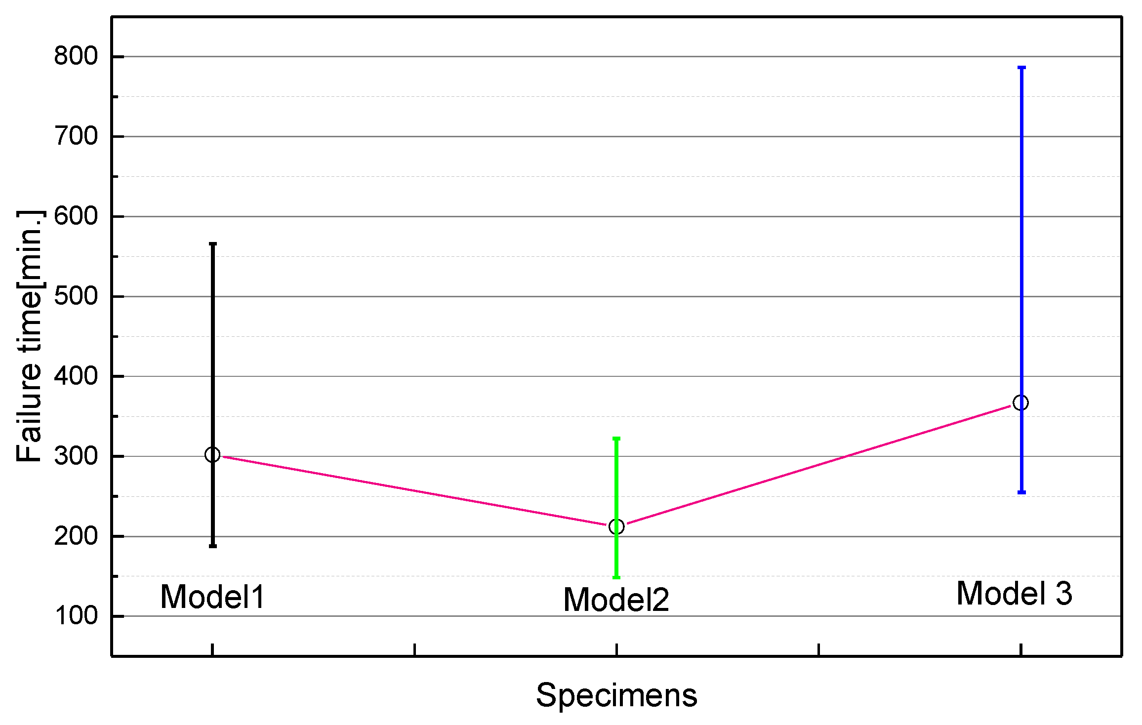
  • The failure time of each specimen was measured in order to determine the degradation degree of the electrical trees by means of F(t) which uses the relevant time as a variable. The failure times in each model were measured and written by the degradation stage, and the shape parameters, the scale parameters and MTTF for each model and each stage were also estimated by means of these measurement results. The time difference between the degradation stages could be calculated, and the remaining lifetime of trees was estimated by means of such time differences.
It is considered that the research performed in this study can be utilized as basic research data for insulation diagnosis and the lifespan estimation of not only power cables but also electric power equipment which uses any different types of insulating material. It is also considered that the data based on this study can be utilized for determining the lifespan estimation and maintenance stages in the continuous monitoring and diagnosis system.

Acknowledgments

This study was supported by R&D Project of Korea Railroad Research Institute. I would really like to thank to Kangwon Lee who works at KRRI for gave me advice and helped me revise this paper.

Author Contributions

Donguk Jang and Seonghee Park conceived experiments and discussed results. Seonghee Park performed the experiments and analyzed the Weibull distribution. Donguk Jang analyzed PD experiment results and wrote this paper.

Conflicts of Interest

The authors declare no conflict of interest.

References

  1. Kreuger, F.H.; Gulski, E.; Krivda, A. Classification of Partial Discharge. IEEE Trans. Electr. Insul. 1993, 28, 917–931. [Google Scholar] [CrossRef]
  2. Gulski, E. Computer-aided Measurement of Partial Discharges in HV Equipment. IEEE Trans. Electr. Insul. 1993, 28, 969–976. [Google Scholar] [CrossRef]
  3. Shimizu, N.; Laurent, C. Electrical Tree Initiation. IEEE Trans. Dielectr. Electr. Insul. 1998, 5, 651–659. [Google Scholar] [CrossRef]
  4. Du, B.X.; Xue, J.S.; Sum, J.G.; Han, T. Effects of ambient temperature on electrical tree in epoxy resin under repetitive pulse voltage. IEEE Trans. Dielectr. Electr. Insul. 2017, 24, 1527–1536. [Google Scholar] [CrossRef]
  5. Bamji, S.S.; Bulinski, A.T.; Chen, Y.; Densley, R.J. Photodegradation versus hot-electron impact for electrical tree inception at low electric fields. In Proceedings of the 3rd International Conference on Properties and Applications of Dielectric Materials, Tokyo, Japan, 8–12 July 1991; Volume 1, pp. 51–54. [Google Scholar] [CrossRef]
  6. Jiang, Y.; Min, H.; Luo, J.H.; Li, Y.; Jiang, X.J.; Xia, R.; Li, W.J. Partial Discharge Pattern Characteristic of HV Cable Joints with Typical Artificial Defect. In Proceedings of the 2010 Asia-Pacific Power and Energy Engineering Conference (APPEEC), Chengdu, China, 28–31 March 2010. [Google Scholar]
  7. Wang, L.; Liang, X.; Guan, Z.; Que, W. Research on 500 kV Phase to Phase Composite Spacer for Compact Lines. In Proceedings of the 6th International Conference on Properties and Applications of Dielectric Materials, Xi’an, China, 21–22 June 2000; pp. 346–349. [Google Scholar]
  8. Guastavino, F.; Cerutti, B. Tree growth monitoring by means of digital partial discharge measurements. IEEE Trans. Dielectr. Electr. Insul. 2003, 10, 65–72. [Google Scholar] [CrossRef]
  9. Tian, Y.; Lewin, P.L.; Wilkinson, J.S.; Sutton, S.J.; Swingler, S.G. Continuous on-line monitoring of partial discharges in high voltage cables. In Proceedings of the Conference Record of the 2004 IEEE International Symposium on Electrical Insulation, Indianapolis, IN, USA, 19–22 September 2004; pp. 454–457. [Google Scholar] [CrossRef]
  10. Fabiani, D.; Simoni, L. Discussion on Application of the Weibull Distribution to Electrical Breakdown of Insulating Materials. IEEE Trans. Dielectr. Electr. Insul. 2005, 12, 6–11. [Google Scholar] [CrossRef]
  11. Shimizu, N.; Sato, H. Role of Electron Impact in AC Electrical Tree Initiation. In Proceedings of the IEEE Transactions on Properties and Applications of Dielectric Materials, Seoul, Korea, 25–30 May 1997; pp. 414–417. [Google Scholar]
  12. Nelson, W. Applied Life Data Analysis; John Wiley & Sons: New York, NY, USA, 1982. [Google Scholar]
  13. Sarathi, R.; Oza, K.H.; Pavan Kumar, C.L.G.; Tanaka, T. Electrical treeing in XLPE cable insulation under harmonic AC voltages. IEEE Trans. Dielectr. Electr. Insul. 2015, 22, 3177–3185. [Google Scholar] [CrossRef]
  14. Jarvid, M.; Johansson, A.; Bjuggren, J.M.; Wutzel, H.; Englund, V.; Gubanski, S.; Müller, C.; Andersson, M.R. Tailored side-chain architecture of benzil voltage stabilizers for enhanced dielectric strength of cross-linked polyethylene. J. Polym. Sci. Part B Polym. Phys. 2014, 52, 1047–1054. [Google Scholar] [CrossRef]
  15. Bahadoorsingh, S.; Rowland, S. Investigating the impact of harmonics on the breakdown of epoxy resin through electrical tree growth. IEEE Trans. Dielectr. Electr. Insul. 2010, 17, 1576–1584. [Google Scholar] [CrossRef]
  16. Park, S.H. Classification of Defects and Evaluation of Electrical Tree Degradation in Cable Insulation Using Pattern Recognition Method and Weibull Process of Partial Discharge. Ph.D. Thesis, Chungbuk National University, Cheongju, Korea, 2007. [Google Scholar]
  17. Woojin, K.; Jeong, J.H.; Kim, Y.; Lim, W.C.; Kim, J.H.; Park, J.H.; Shin, H.J.; Park, Y.S.; Kim, K.S.; Park, S.H. Classification of defects and evaluation of electrical tree degradation in cable insulation using pattern recognition method and weibull process of partial discharge. In Proceedings of the 2008 International Conference on Condition Monitoring and Diagnosis, Beijing, China, 21–24 April 2008; pp. 101–104. [Google Scholar]
  18. Park, S.H.; Lim, K.J.; Kang, S.H. Comparison of Classification Rate for PD Sources using Different Classification Schemes. J. Electr. Eng. Technol. 2006, 1, 257–262. [Google Scholar] [CrossRef]
  19. Park, S.H.; Jang, D.U.; Kang, S.H.; Lim, K.J. Off-line PD Model Classification of Traction Motor Stator Coil Using BP. KIEE Int. Trans. Electrophys. Appl. 2005, 5-C, 223–227. [Google Scholar]
  20. Steennis, F.; Wagenaars, P.; van der Wielen, P.; Wouters, P.; Li, Y.; Broersma, T.; Harmsen, D.; Bleeker, P. Guarding MV cables on-line: With travelling wave based temperature monitoring, fault location, PD location and PD related remaining life aspects. IEEE Trans. Dielectr. Electr. Insul. 2016, 23, 1562–1569. [Google Scholar] [CrossRef]
Figure 1. Artificial electric tree models: (a) tree model 1 was only needle electrode; (b) tree model 2 with void on needle electrode surface; (c) tree model 3 with metal particle between needle and ground electrode [18,19,20].
Energies 10 01789 g001
Figure 2. This is the test process of the experimental setup to detect the partial discharge (PD): (a) test process; (b) Partial discharge detector system.
Energies 10 01789 g002
Figure 3. This is diagram of the tree image observation process and setup to see the tree propagation image: (a) Tree image observation process; (b) Microscope and Charge Coupled Device (CCD) with test specimen.
Energies 10 01789 g003
Figure 4. Statistical distributions of PD for tree model 1: (a) Hn(q) distribution; (b) Hn(Φ) distribution; (c) Hqn(Φ) distribution; (d) Hqmax(Φ) distribution.
Energies 10 01789 g004
Figure 5. Statistical distributions of PD for tree model 2: (a) Hn(q) distribution; (b) Hn(Φ) distribution; (c) Hqn(Φ) distribution; (d) Hqmax(Φ) distribution.
Energies 10 01789 g005
Figure 6. Statistical distributions of PD for tree model 3: (a) Hn(q) distribution; (b) Hn(Φ) distribution; (c) Hqn(Φ) distribution; (d) Hqmax(Φ) distribution.
Energies 10 01789 g006
Figure 7. Mean of statistical distributions of PD for tree models: (a) Hn(q) distribution; (b) Hn(Φ) distribution; (c) Hqn(Φ) distribution; (d) Hqmax(Φ) distribution.
Energies 10 01789 g007
Figure 8. Time of failure according to tree models.
Energies 10 01789 g008
Figure 9. Time to failure of the Weibull distribution of tree model 1 (divided by three progress: initiation, middle, failure).
Energies 10 01789 g009
Figure 10. Time to failure of the Weibull distribution of tree model 2 (divided by three progress: initiation, middle, failure).
Energies 10 01789 g010
Figure 11. Time to failure of the Weibull distribution of tree model 3 (divided by three progress: initiation, middle, failure).
Energies 10 01789 g011
Table 1. Time to failure of tree model 1.
Specimen NumberInitiation (Min.)Middle (Min.)Failure (Min.)
12590200
230100225
330110245
42595210
535125270
640140305
740135300
875255565
935115250
1035120260
1165225495
1245155345
1360190425
1435115250
1535125280
1640130285
Average time41139307
Table 2. Shape and scale parameter of tree model 1.
ParameterInitiationMiddleFailure
Grouping ShapeScale
(Min.)
MTTF
(Min.)
ShapeScale
(Min.)
MTTF
(Min.)
ShapeScale
(Min.)
MTTF
(Min.)
subpopulation 16.337418.41241378271302
subpopulation 27.5703.32124.6495
Table 3. Time to failure of tree model 2.
Specimen NumberInitiation (Min.)Middle (Min.)Failure (Min.)
13263210
22651170
32960195
43366220
53672240
63263210
72445155
83162205
93774245
103463225
1153105350
123367220
132957190
142856185
153266215
163158205
Average time3364215
Table 4. Shape and scale parameter of tree model 2.
InitiationMiddleFailure
ShapeScale
(Min.)
MTTF
(Min.)
ShapeScale
(Min.)
MTTF
(Min.)
ShapeScale
(Min.)
MTTF
(Min.)
7.534327.0368647.64226212
Table 5. Time to failure of tree model 3.
Specimen NumberInitiation (Min.)Middle (Min.)Failure (Min.)
145130285
245125280
360170380
440120270
543130290
652155345
750152335
875225495
950147325
10120355790
1150150330
1248140310
13100208640
1455160355
1540120265
1650150330
Average time58165377
Table 6. Shape and scale parameter of tree model 3.
ParameterInitiationMiddleFailure
Grouping ShapeScale
(Min.)
MTTF
(Min.)
ShapeScale
(Min.)
MTTF
(Min.)
ShapeScale
(Min.)
MTTF
(Min.)
Subpopulation 110.850569.11501619.3329367
Subpopulation 22.9982.92934.1700

