Impact-Based Electromagnetic Energy Harvester with High Output Voltage under Low-Level Excitations

1
Key Laboratory of Optoelectronic Technology and Systems of the Education Ministry of China, Chongqing University, Chongqing 400044, China
2
College of Optoelectronic Engineering, Chongqing University, Chongqing 400044, China
*
Author to whom correspondence should be addressed.
Energies 2017, 10(11), 1848; https://doi.org/10.3390/en10111848
Submission received: 10 August 2017
/
Revised: 8 November 2017
/
Accepted: 10 November 2017
/
Published: 14 November 2017
(This article belongs to the Section L: Energy Sources)
Abstract
:To expand the applications of vibrational energy harvesters (VEHs) as power sources of wireless sensor nodes, it is of significance to improve the scavenging efficiency for the broadband, low-frequency, and low-level vibrational energy. The output voltages of electromagnetic vibrational energy harvesters (EMVEHs) are usually low, which complicates the power management circuit by an indispensable voltage boosting element. To this end, an impact-based non-resonant EMVEH mainly composed of an outer frame and an inner frame on rollers is proposed. Numerical simulations based on a mathematical model of the harvester are conducted to analyze the effects of structural parameters on the output performance. Under base excitation of 0.1 and 0.3 (where is the gravitational acceleration, 1), the experimental maximum root mean square voltages of a harvester prototype across a resistor of 11 kΩ are as high as 7.6 and 16.5 V at 6.0 and 8.5 Hz, respectively, with the maximum output powers of 5.3 and 24.8 mW, or the power densities of 54.6 and 256 μW cm−3. By using a management circuit without a voltage boosting element, a wireless sensor node driven by the prototype can measure and transmit the temperature and humidity every 20 s under base excitation of 0.1 at 5.4 Hz.
1. Introduction
Vibration energy harvesters (VEHs) are promising substitutes to batteries to power wireless sensor nodes and implanted systems due to such advantages as long lives and being maintenance-free [1,2]. The vibrations in natural environments (e.g., trees, civil infrastructures, buildings, waves) are typically broadband (and sometimes time-varying), low-frequency (0.1–30 Hz), and low-level (lower than 1, for example, the typical acceleration amplitude on long-span bridges is from 0.01 to 0.3) [3,4,5]. The relatively high natural frequencies and narrow bandwidth of the linear resonant VEHs make them inefficient in scavenging ambient broadband and low-frequency vibration energy [5,6]. Therefore, non-resonant VEHs have received increasing attention in recent years [7,8,9,10].
A type of non-resonant VEHs utilizing the nonlinearity caused by mechanical impacts is attractive in low-frequency and broadband vibration energy scavenging. An impact-based piezoelectric VEH with a low-frequency driving beam and a high-frequency generating beam produced 0.43 mW under base excitation of 0.4 at 8.2 Hz [11]. The long length and large displacement of the driving beam increases the volume of the device, resulting in a relatively low power density of about 25.5 μW cm−3. Halim et al. developed an electromagnetic VEH (EMVEH) suitable to scavenge low-frequency motions, by utilizing the impacts between a freely-movable ball and the magnet stacks [12]. The experimental average output power is about 203 μW under base excitation of 2 at 4.9 Hz, with the maximum power density of 52 μW cm−3. Haroun et al. reported an impact-based EMVEH with a permanent magnet mass which can move freely within a certain distance before striking the springs [13]. The mathematical model was derived and effects of the geometrical parameters on the output performance were simulated. The power magnification effect of this device was verified by experiments. A VEH based on the impact of a moving mass on piezoelectric bending structures produces an output power of 600 μW under a harmonic base excitation with the displacement amplitude of 10 cm and frequency of 10 Hz [14]. As the authors pointed out, the sliding friction between the moving mass and the guiding channel dramatically decreases the efficiency of the device. In addition, the relatively high sliding friction makes it not suitable to scavenge low-level base motions. As the rolling friction is usually much lower than the sliding friction, the impact-based VEHs with a rolling mass are preferred in low-level vibration energy scavenging. By replacing the sliding mass with a rolling ball, the performance of low-level vibration energy scavenging is greatly improved [15]. One bimorph of a piezoelectric VEH with a rolling mass produces 98.0 μW under base excitation of 0.1 at 8.8 Hz [16]. Accordingly, it may be concluded that the impact-based non-resonant VEHs with a rolling mass are suitable to scavenge low-level, broadband, and low-frequency vibration energy.
The electromagnetic, piezoelectric, or electrostatic transduction mechanisms have been used by VEHs to convert mechanical energy into electricity [17,18,19,20,21,22,23,24]. The advantages of EMVEHs, such as high power density and high reliability, make them attractive in real applications. Compared with piezoelectric and electrostatic VEHs, the output voltage of EMVEHs is relatively low, with the typical root-mean-square values lower than 1 V [5,8,10,12]. Therefore, a voltage boosting element is required in the power management circuits [10]. This paper proposed an impact-based electromagnetic VEH which produces high output voltage even under low-level base excitation, making the voltage boosting element of the management circuit dispensable. A simple model is used to analyze the effects of some parameters on the output performance. Prototypes were fabricated and tested and a prototype was used to power a wireless sensor node.
2. Configuration and Operational Mechanism
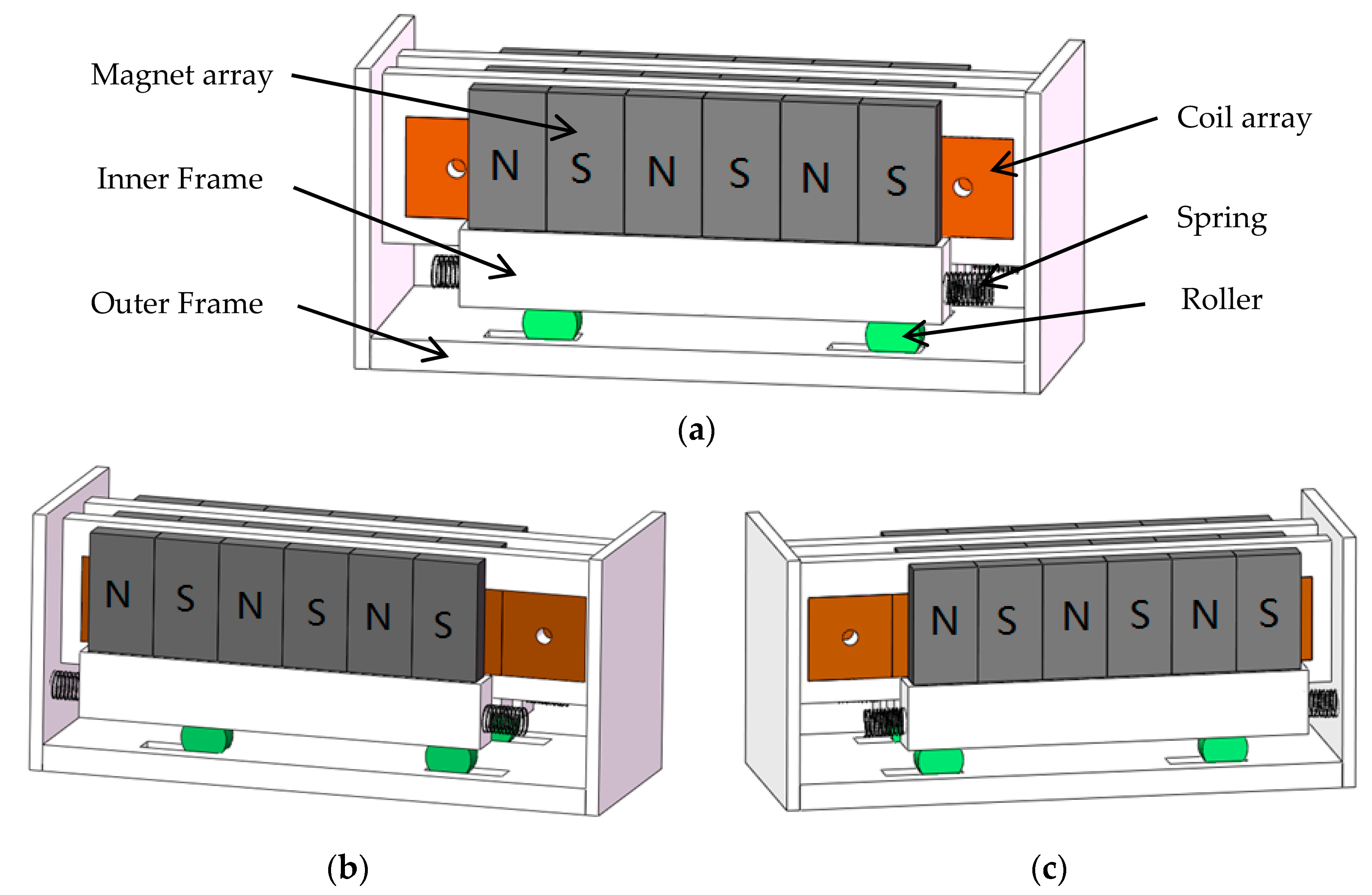
The proposed impact-based non-resonant electromagnetic kinetic energy harvester is schematically shown in Figure 1. The harvester mainly consists of an outer frame, an inner frame, rollers, and springs. The inner frame is supported on the floor of the outer frame by the rollers. Thin rectangular permanent magnets, with the magnetic field in the thickness direction, are lined up next to each other along the width direction to form rows of magnets. The magnetic field directions of two adjacent magnets in the same row are opposite. Several magnet rows are placed parallel to each other with the same separation distance. The magnets in the adjacent rows facing each other are arranged in opposite polarities, making two adjacent rows of the magnet array attract each other. Similarly, rectangular metal coils are lined up next to each other to form coil rows and a coil array is formed by setting a coil row in the middle of any two adjacent magnetic rows. The coil array and the magnet array are fixed on the outer frame and inner frame, respectively. Several springs are fixed on the left and right sides of the inner frame, respectively. There are initial gaps between the free ends of the springs and the walls of the outer frame. Under horizontal base excitations, the inner frame moves with respect to the outer frame on the rollers, resulting in magnetic flux variations through the coils and, consequently, producing induced electromotive forces in the coils. The restoring forces of the springs are determined by the relative positions of the outer and inner frames. As shown in Figure 1, when the relative displacement between two frames exceeds the initial gaps between the springs on the inner frame and the walls of the outer frame, the springs at the left or right sides of the inner frame are compressed and the restoring forces make the inner frame return to the center of the outer frame. Otherwise, there are no restoring forces in the springs and the inner frame is freely movable on the floor of the outer frame. The energy loss in collisions is decreased by setting springs between the inner and outer frames.
The harvester is suitable to scavenge low-level, broadband, and low-frequency vibrational energy. It is a non-resonant harvester with a movable proof mass and, as a result, it can be used to scavenge low-frequency and broadband vibrational energy. In addition, because the rolling friction force between the rollers and the frames is very small, the inner frame is prone to move with respect to the outer frame, which is beneficial to low-level kinetic energy scavenging.
The output voltage of this electromagnetic energy harvester can be improved by the following measures. First, the output voltage can be maximized by electrically connecting the coils in series. Under the condition of the same volume, the number of the turns of coils increases with the decrease of the diameter of the coil wire, resulting in an increased induced electromotive force. Therefore, the output voltage can also be increased by using coils with more turns.
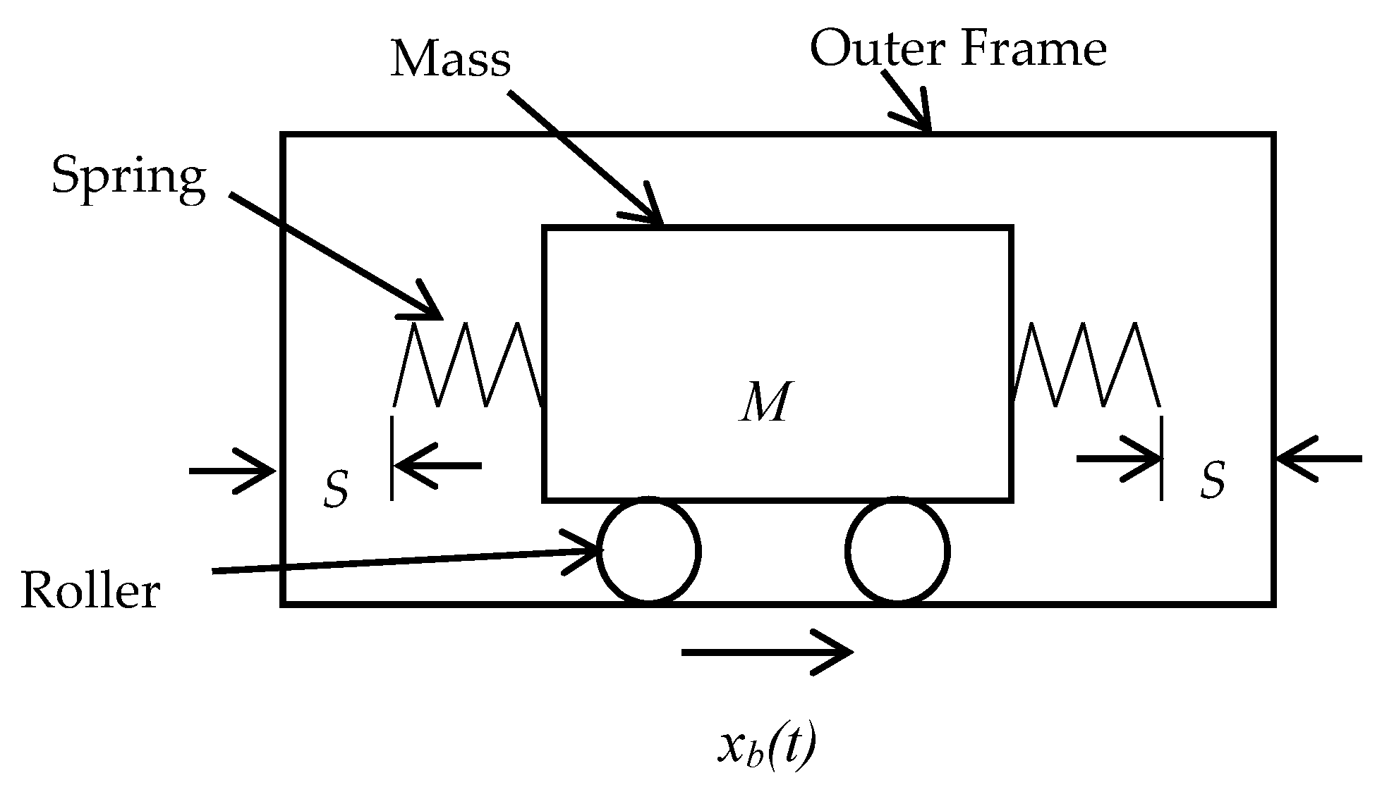
The motion of the proposed EMVEH is schematically shown in Figure 2. It is assumed that the inner frame with the mass of M is at the center of the outer frame at the beginning and the initial gaps between the free ends of the springs and the opposite walls of the outer frame are set as S. The horizontal base excitation is denoted by xb(t) and the displacement of the inner frame with respect to the outer frame is xr(t).
The equation of motion of the inner frame is given by [13]:
where a dot represents a derivative with respect to time, μ is the coefficient of rolling friction. The mechanical damping coefficient Cm can be expressed as Cm = Cv + Ci [13,25], where Cv is the linear viscous damping coefficient and Ci is the additional damping coefficient when the springs are in contact with the outer frame. The expression of Ci is as follows [13]:
By neglecting the effects of the coil inductance, the electrical damping coefficient Ce can be expressed as [13,25]:
where is the total magnetic flux going through the coil turns, and RC and RL are the resistance of the coils and the electrical load, respectively. The effective stiffness of the springs K is given by [13]:
Under base excitations, the displacements and velocities of the inner frame with respect to the outer frame can be obtained by solving Equation (1). According to Faraday’s law of induction, the induced electromotive force in the coils due to the relative motion of the mass and the outer frame is given by [13]:
Therefore, the output voltage across the electrical load is about:
To obtain the output voltage across the electrical load, the rate of change of total magnetic flux with respect to the relative displacement () has to be obtained in advance. The total magnetic flux and its rate of change at any specified displacement can be derived from the configuration of the coils and the distribution of magnetic flux density between two rows of magnets. After substituting into Equation (3) to obtain the electrical damping coefficient Ce, the displacement and velocity of the inner frame with respect to the outer frame can be derived from Equation (1). Then, the output voltage across the load can be obtained from Equation (6).
3. Numerical Simulations and Discussions
The initial gap between the free ends of the springs and the outer frame and the stiffness of the springs affect the performance of the proposed harvester [13]. As an example, the responses of a harvester with a coil at the center of a 2 × 2 magnet (N-50 graded NdFeB) array, with the parameters listed in Table 1, was simulated. The inner and outer side lengths of the coils are about 3 and 9 mm, respectively, with a cross-section of about 3 mm × 3 mm. Here, the finest commercially-available copper wire with a diameter of 50 μm is used to wind the coils. By setting the copper fill factor as 0.55, we obtained the number of coil turns, about 2500 [26]. As the coefficient of rolling friction is as low as 0.002 [27], the friction force is neglected in the simulations.
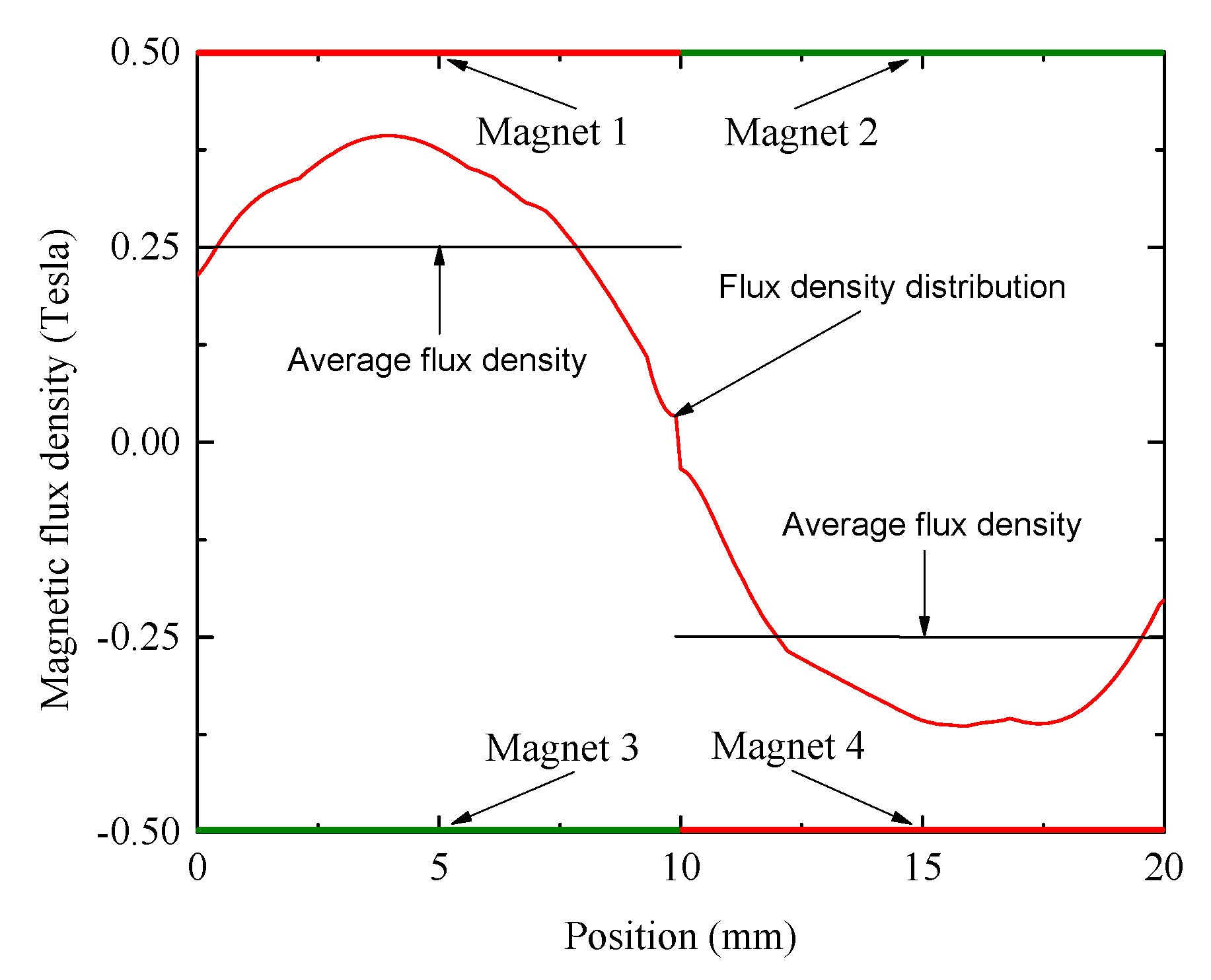
By using the commercial finite element software ANSYS (ANSYS Inc., Pittsburgh, PA, USA) to establish the three dimensional finite element model of the magnet array, the magnetic flux density in the air gap between the two adjacent pairs of magnets was simulated. Figure 3 gives the distribution of the magnetic flux density along the centerline of the air gap. The average magnetic flux field density is about 0.25 T, and polarity reversals occurs at the junction (position = 10 mm) between the two sets of magnets.
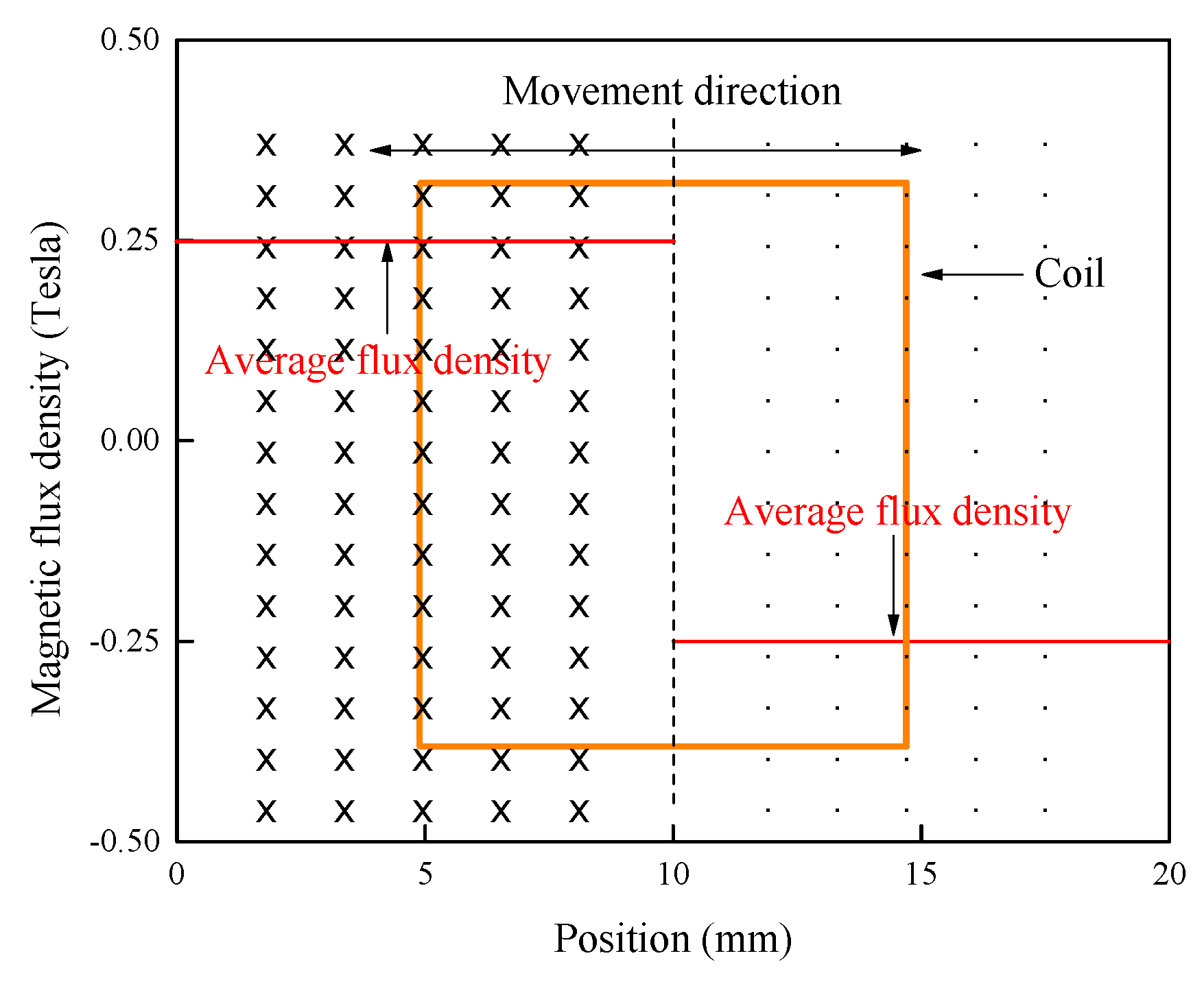
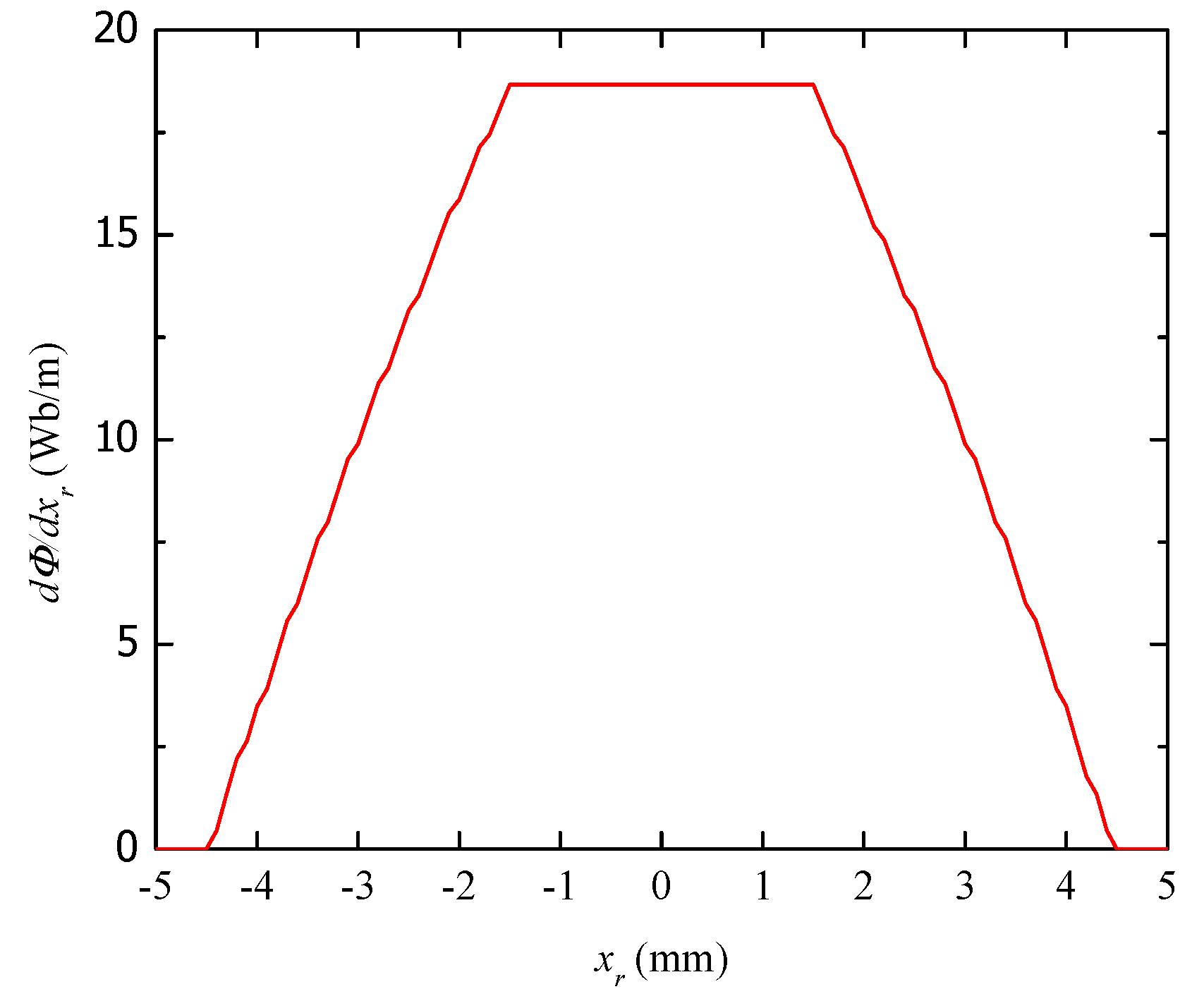
When a coil is at the center of the magnet array, as shown in Figure 4, the base excitation causes the inner frame to move in direction with respect to the outer frame, resulting in an induced voltage across the coil. By setting the magnetic flux density with the value of 0.25 T for and −0.25 T for , the rate of change of total magnetic flux with respect to the relative displacement was worked out with , as shown in Figure 5. The rate of change of total flux takes the maximum value of about 19 Wb m−1 when the relative displacement is close to zero.
After the relationship between and was obtained, the responses of the device can be obtained by using MATLAB (Math Works Inc., Natick, MA, USA). In the simulations, the time interval is set as , and the initial conditions are set as and at the beginning with . The electrical damping coefficient Ce at this moment can be obtain from Equation (3). Substituting Ce and the base acceleration at into Equation (1), the displacement and velocity at can be obtained. And the voltage across the resistance at can be calculated form Equation (6). Step by step, the responses of the harvester at time , where is an integer, can be worked out. The accuracy of the responses can be improved by decreasing the time interval .
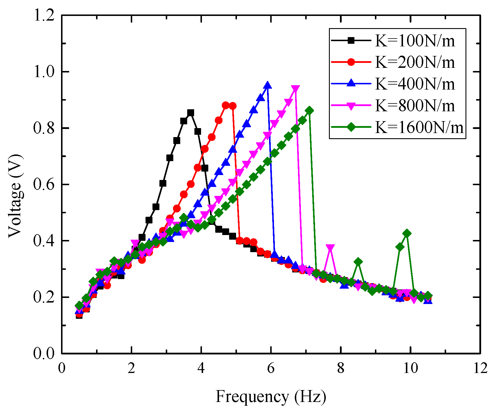
First, the effects of the spring stiffness were simulated. The initial gap between the free ends of the springs and the outer frame is set as 5 mm. Under the harmonic base excitation with the acceleration amplitude of 0.2 , for the prototypes with the spring stiffness of 100, 200, 400, 800, and 1600 N m−1, the simulated root-mean-square (RMS) voltages across a resistor of 800 Ω versus the excitation frequency are given in Figure 6. The excitation frequency corresponding to the maximum output voltage decreases with the reduction of the spring stiffness. In other words, more flexible springs should be used to scavenge vibrational energy at lower frequencies.
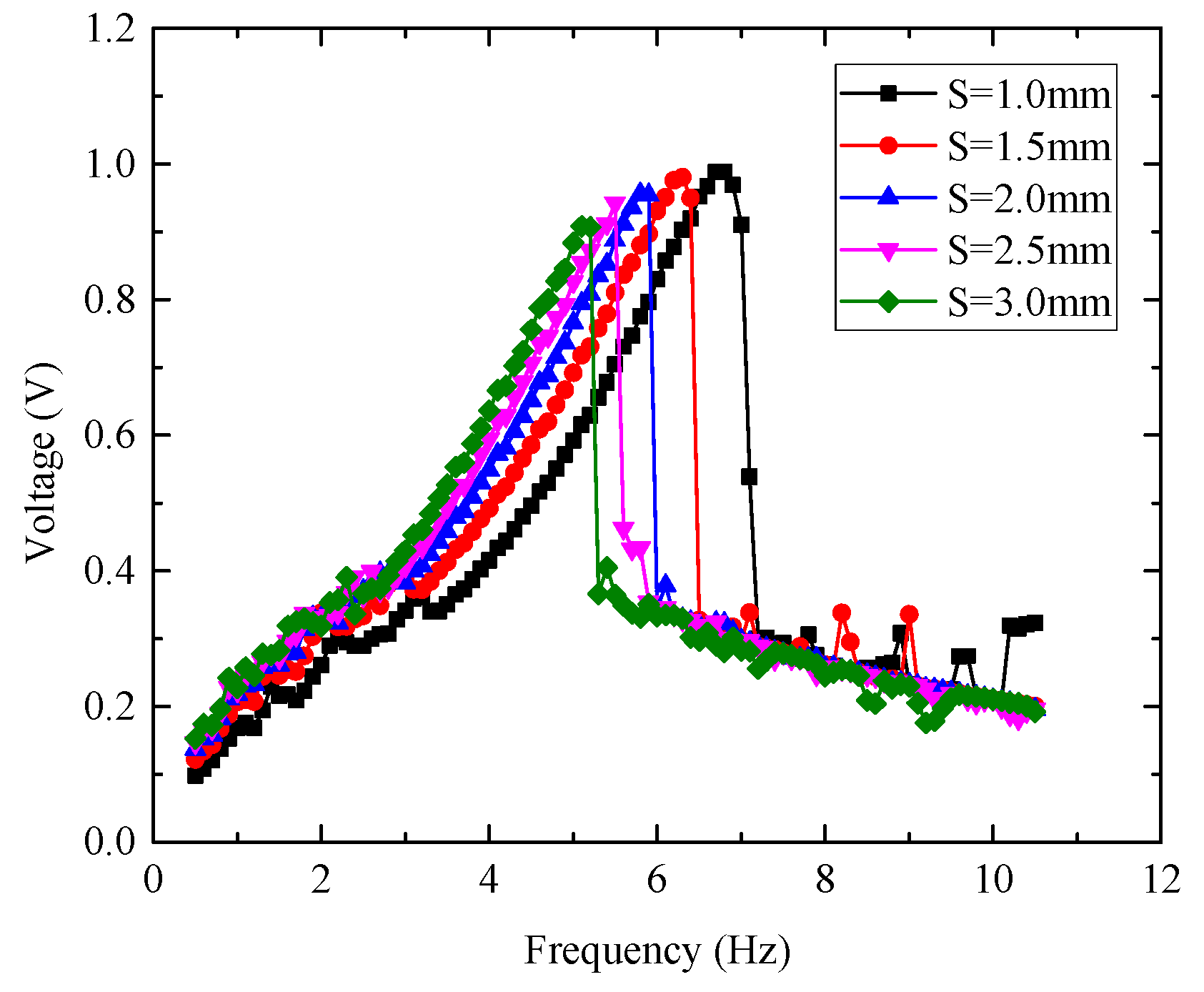
To evaluate the effects of initial gap between the free ends of the springs and the outer frame, the output voltage of the devices with the spring stiffness of 300 N m−1 was simulated. The initial gap is set as 1, 1.5, 2, 2.5, and 3 mm, respectively. Under the harmonic base excitation of 0.2, the simulated output voltages across the resistor of 800 Ω are given in Figure 7. The excitation frequency corresponding to the peak voltage decreases when the initial gap increases. Accordingly, the initial gap should be increased to collect vibration energy with lower frequency. However, as Haroun et al. pointed out [13], the base excitation exerts restrictions on the selection of the initial gap. To make the inner frame strike one side of the outer frame, followed by another collision with the other side in every excitation period, the displacement amplitude of the base excitation should be somewhat larger than the initial gap.
4. Experimental Investigation
4.1. Prototypes of the Impact-Based EMVEH
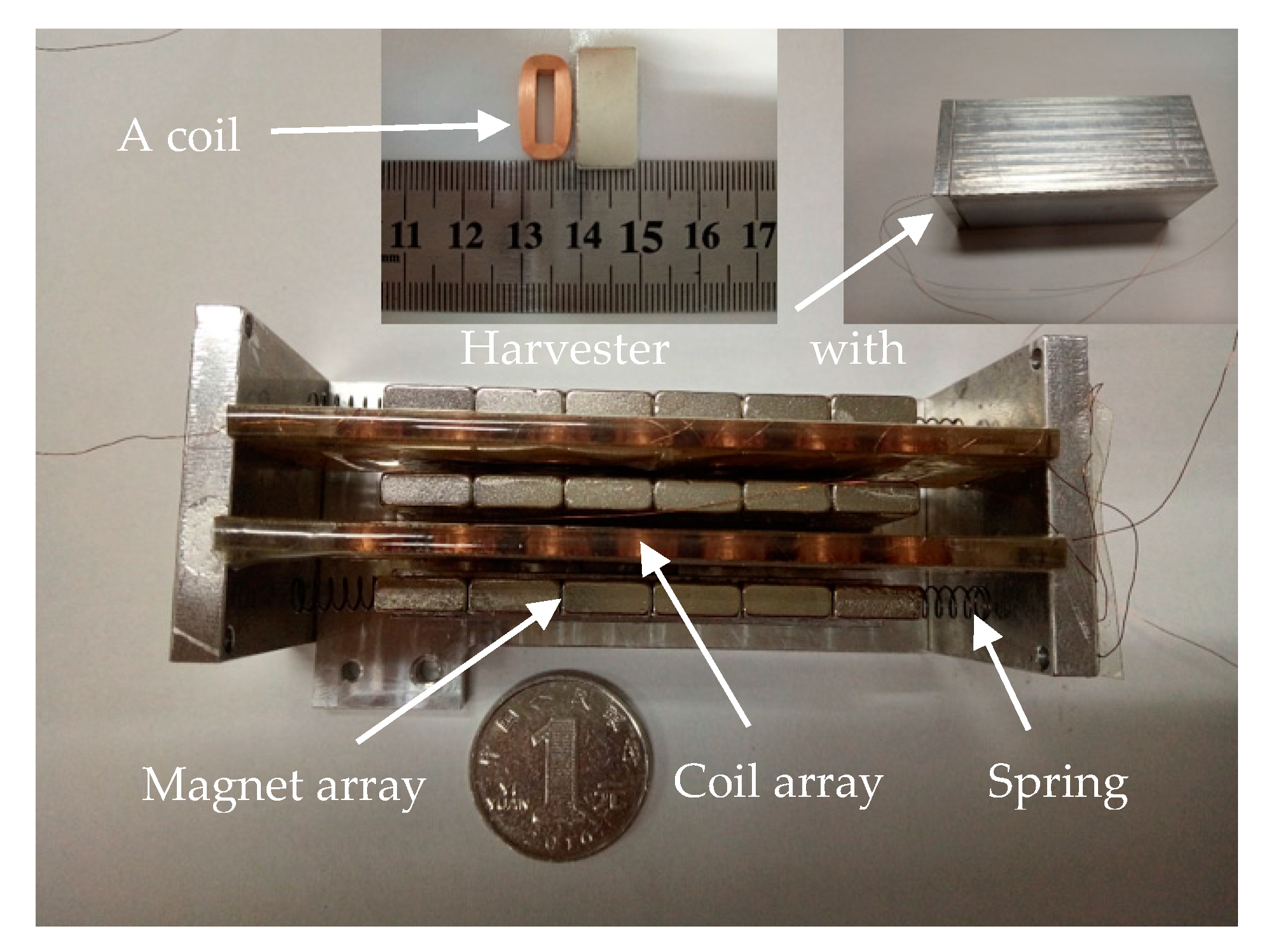
Prototypes with three rows of magnets and two rows of coils were fabricated, as shown in Figure 8. The parameters of the coils and the magnets (N-50 graded NdFeB) were given in Table 1. There are six magnets in a row of magnets and seven coils in a row of coils. The net distance between the two rows of magnets is 7 mm. The inner dimensions of the outer frame are 84 mm × 33 mm × 35 mm, with the internal volume of about 97 cm3. Three prototypes with the parameters listed in Table 2 were fabricated. Prototypes VEH 1 and VEH 2 have the same spring stiffness, but different initial gaps. Prototypes VEH 2 and VEH 3 have the same initial gap but different spring stiffness. The masses of the inner frames of the three prototypes are almost the same, of about 0.108 kg. The effective spring stiffness was worked out from the shear modulus, the wire diameter, the mean diameter, and the number of active coils of the springs [29].
4.2. Experiments and Discussions
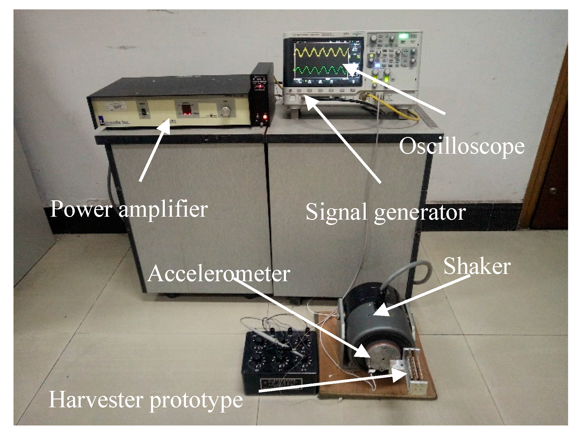
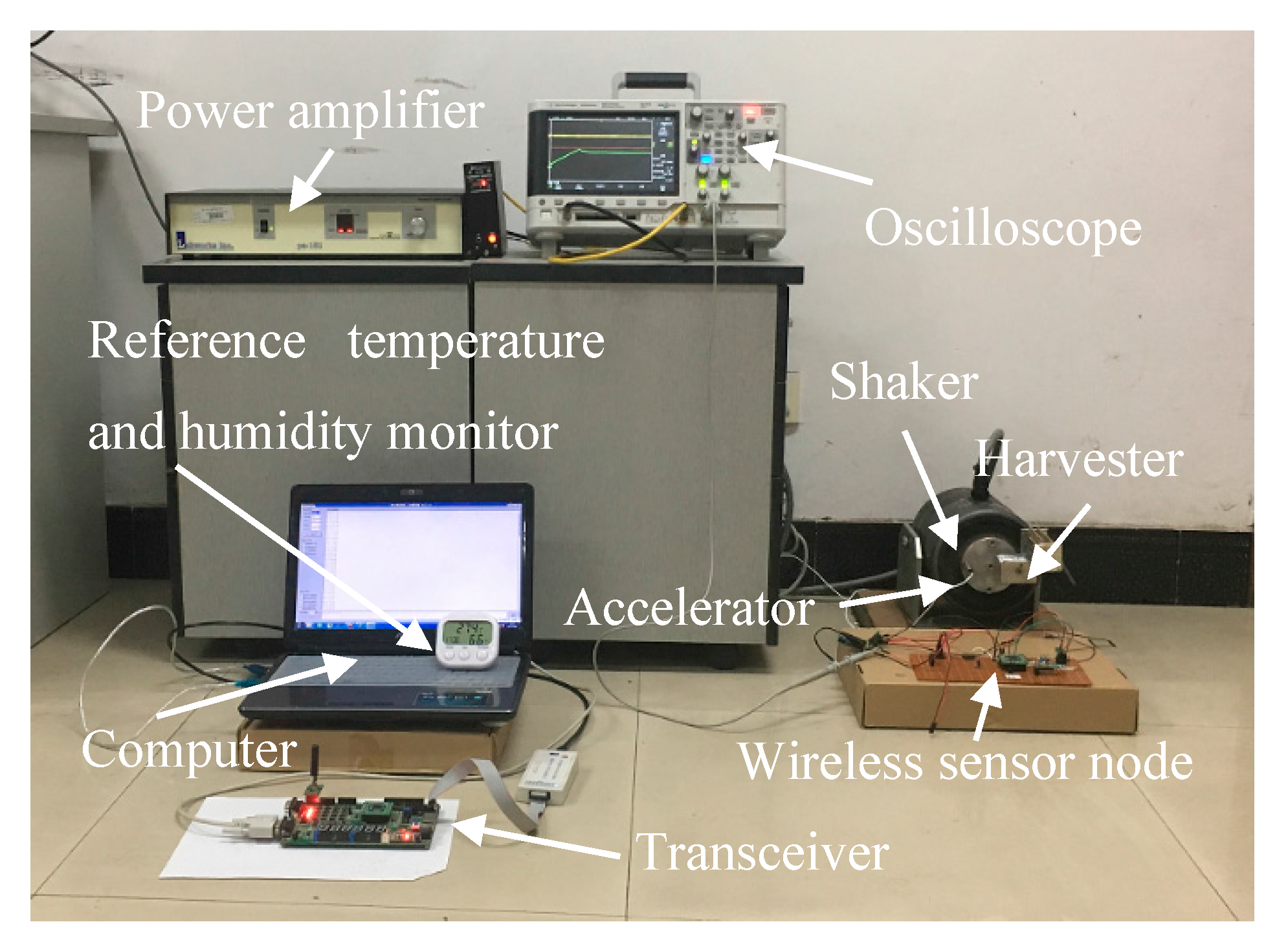
The experimental setup is given in Figure 9. The fabricated VEHs were horizontally mounted on an electromagnetic shaker. A harmonic voltage signal from the signal generator of an oscilloscope was enlarged by a power amplifier to drive the shaker. The acceleration of the shaker and the output voltages of the VEH were monitored by the oscilloscope.
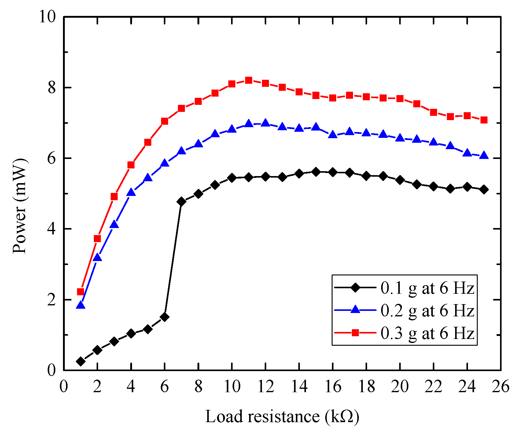
To investigate the optimal electrical load, the RMS voltages of VEH 1 across resistors with different resistances were measured. The output powers of the harvesters can be worked out according to the experimental RMS voltage. The curves of the output power versus the load resistance under harmonic base excitations with the acceleration amplitudes of 0.1, 0.2, and 0.3 at 6 Hz are shown in Figure 10. The output power reaches the maximum values when the load impedance is about 11 kΩ, very close to the total resistance of the coil array 11.2 kΩ. In the following, a resistor of 11 kΩ was connected with the prototypes to evaluate the performances.
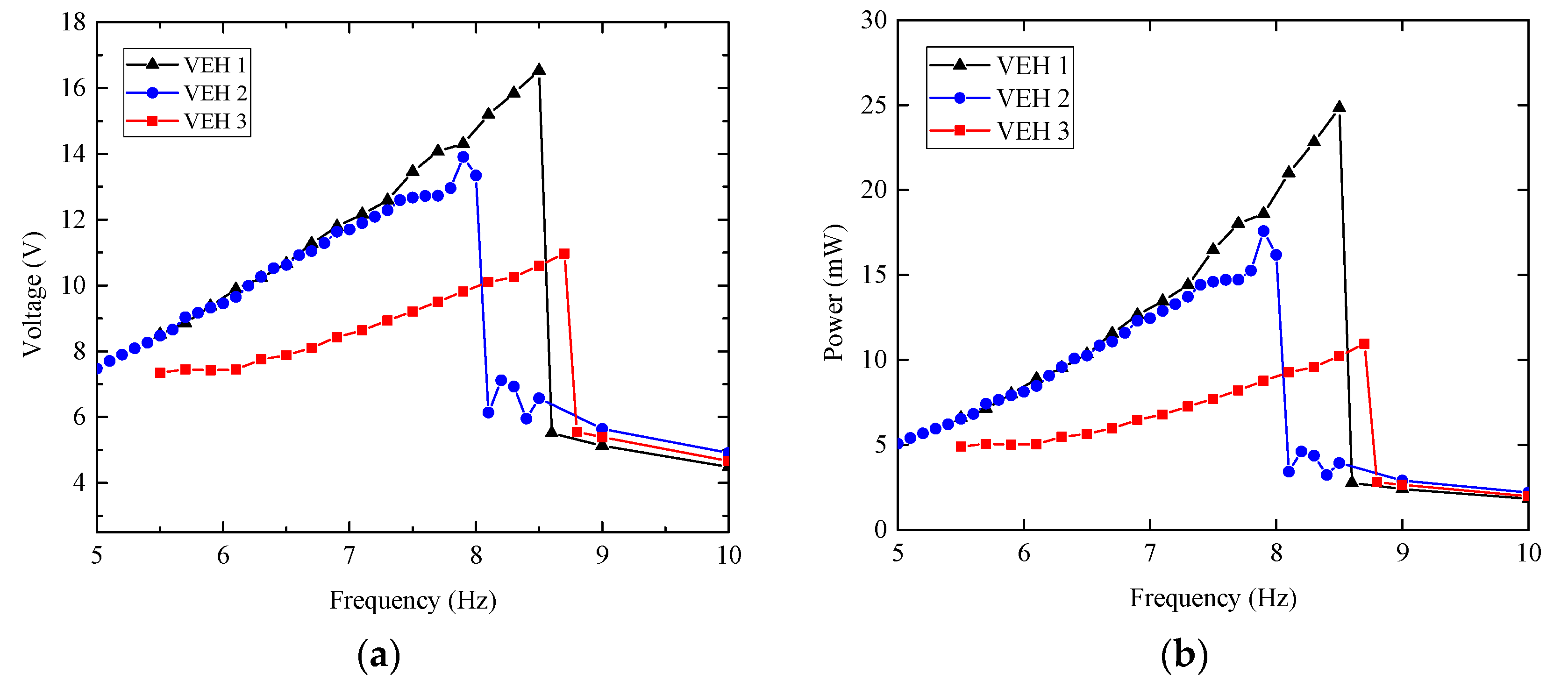
Under the base excitations of 0.3, the experimental RMS voltages and output powers of the three prototypes were plotted in Figure 11. As shown in Figure 11a, the maximum RMS voltages of VEH 1, VEH 2, and VEH 3 across the resistor of 11 kΩ are 16.5, 13.9 and 11.0 V, with the excitation frequency of 8.5, 7.9, and 8.7 Hz, respectively. As the initial gap of VEH 2 is wider than that of VEH 1 and the spring stiffness of VEH 1 is smaller than that of VEH 3, the experimental results demonstrate that, just as the simulation predicts, increasing the initial spacing and decreasing the spring stiffness of the harvester can shift the peak voltage to a lower frequency [13]. The maximum output powers of the three prototypes are about 24.8, 17.6, and 11.0 mW, with the maximum power densities of about 256, 181, and 113 μW cm−3, respectively.
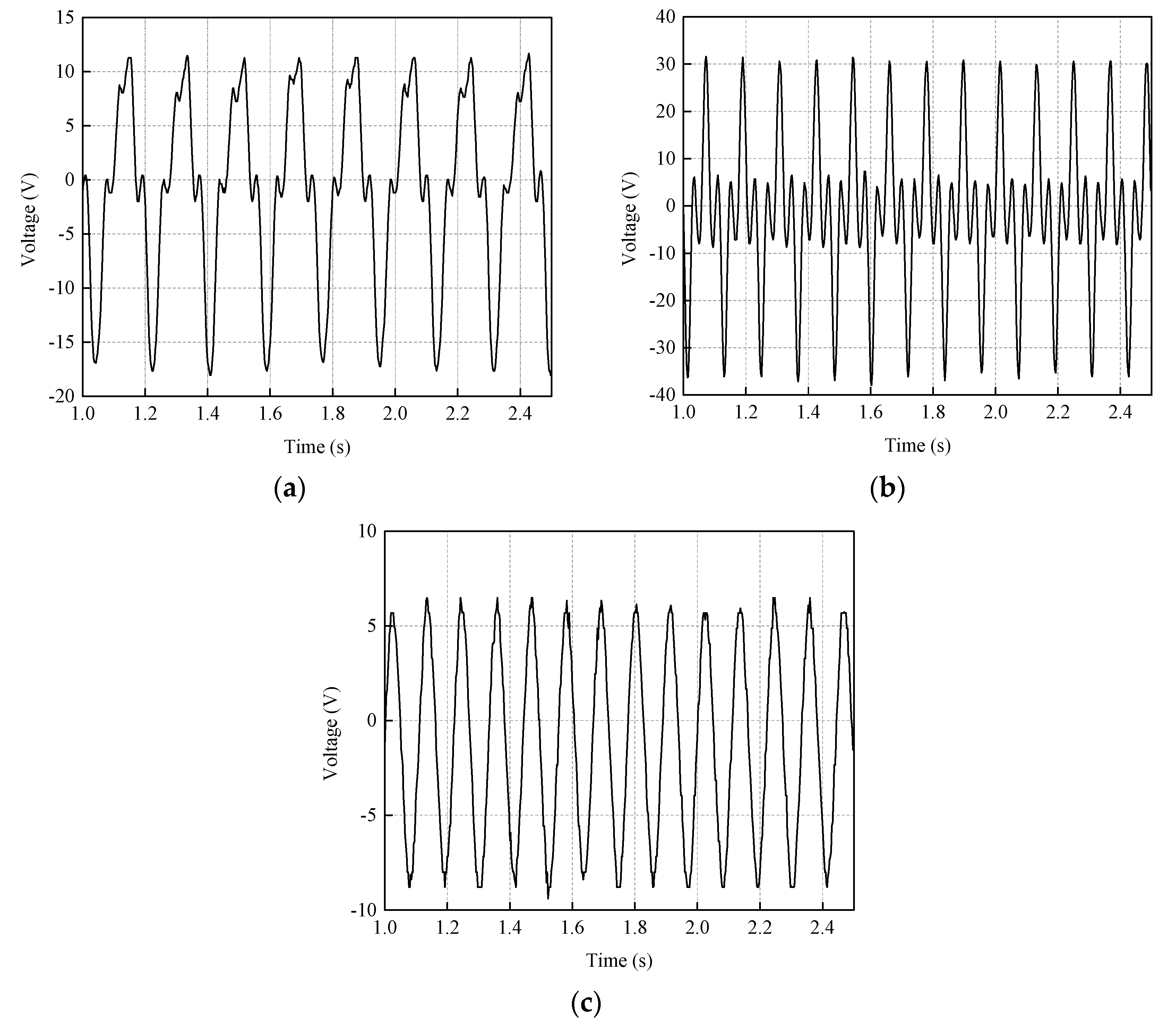
To give more details of the electrical outputs, the time histories of the voltage across the resistor for VEH 1 under base excitations of 0.3 at 5.5, 8.5, and 10 Hz are given in Figure 12. When the excitation frequency increases from 5.5 to 8.5 Hz, there are stable collisions between the inner and the outer frames, as shown in Figure 12a,b. Each collision causes the harvester to produce a relatively high peak voltage, the peak-to-peak voltages are about 26 and 65 V, respectively. When the excitation frequency increases to 10 Hz, as shown in Figure 12c, the inner frame does not impact with the outer frame, and the peak-to-peak voltage is about 14 V, much lower than that at 5.5 to 8.5 Hz.
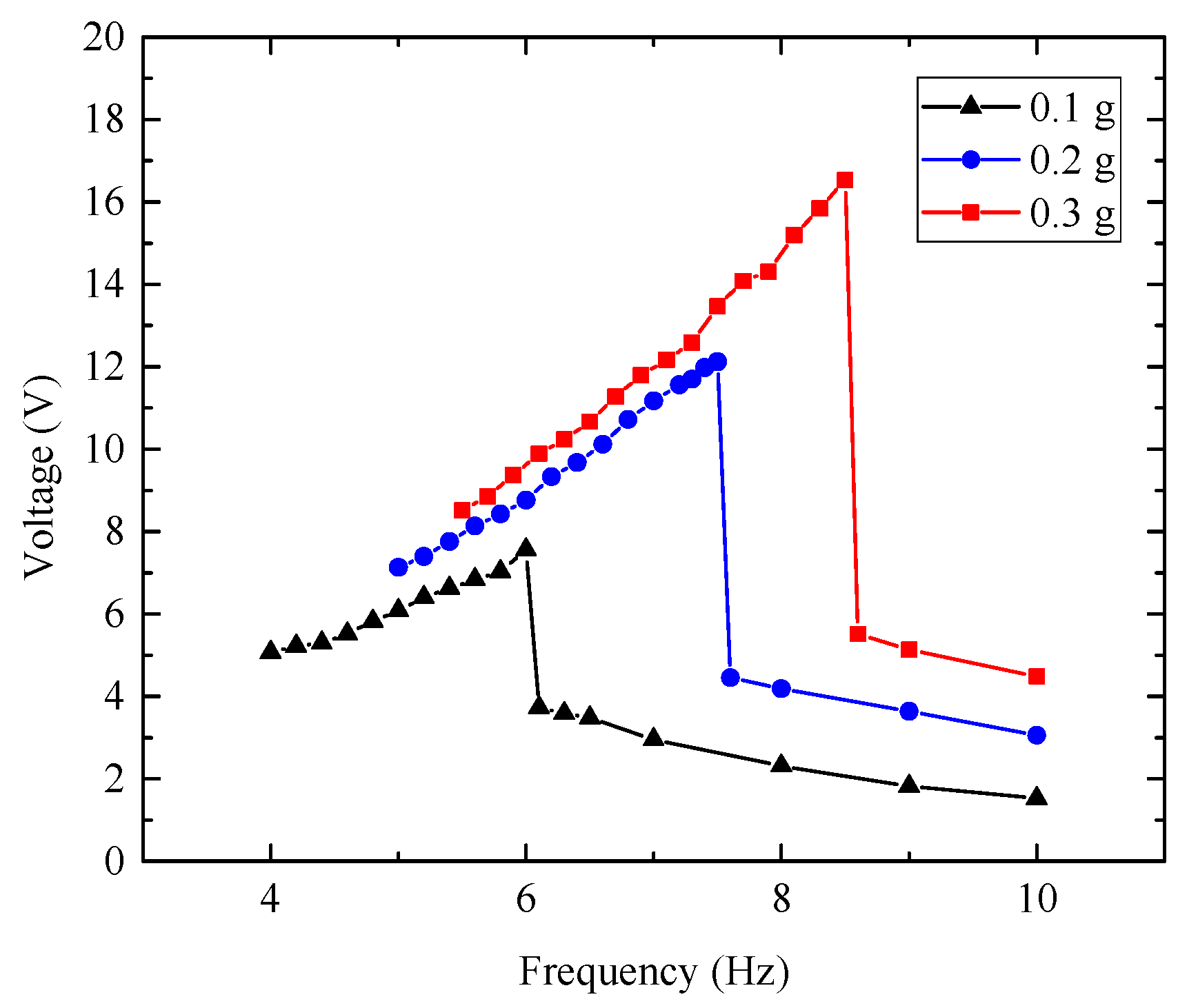
The effects of the base acceleration amplitude on the electrical output of the harvester were measured. For VEH 1, Figure 13 gives the experimental RMS voltages across the resistor under base excitation of 0.1, 0.2, and 0.3, respectively. The experimental maximum RMS voltages are 7.6, 12.1, and 16.5 V at 6.0, 7.5, and 8.5 Hz, respectively. The maximum powers are about 5.3, 13.3, and 24.8 mW, with the maximum power density of about 54.6, 137, and 256 μW cm−3, respectively. Therefore, with the increase of the base acceleration amplitude, the maximum output voltages increase greatly and the excitation frequencies corresponding to the peak electrical output increases.
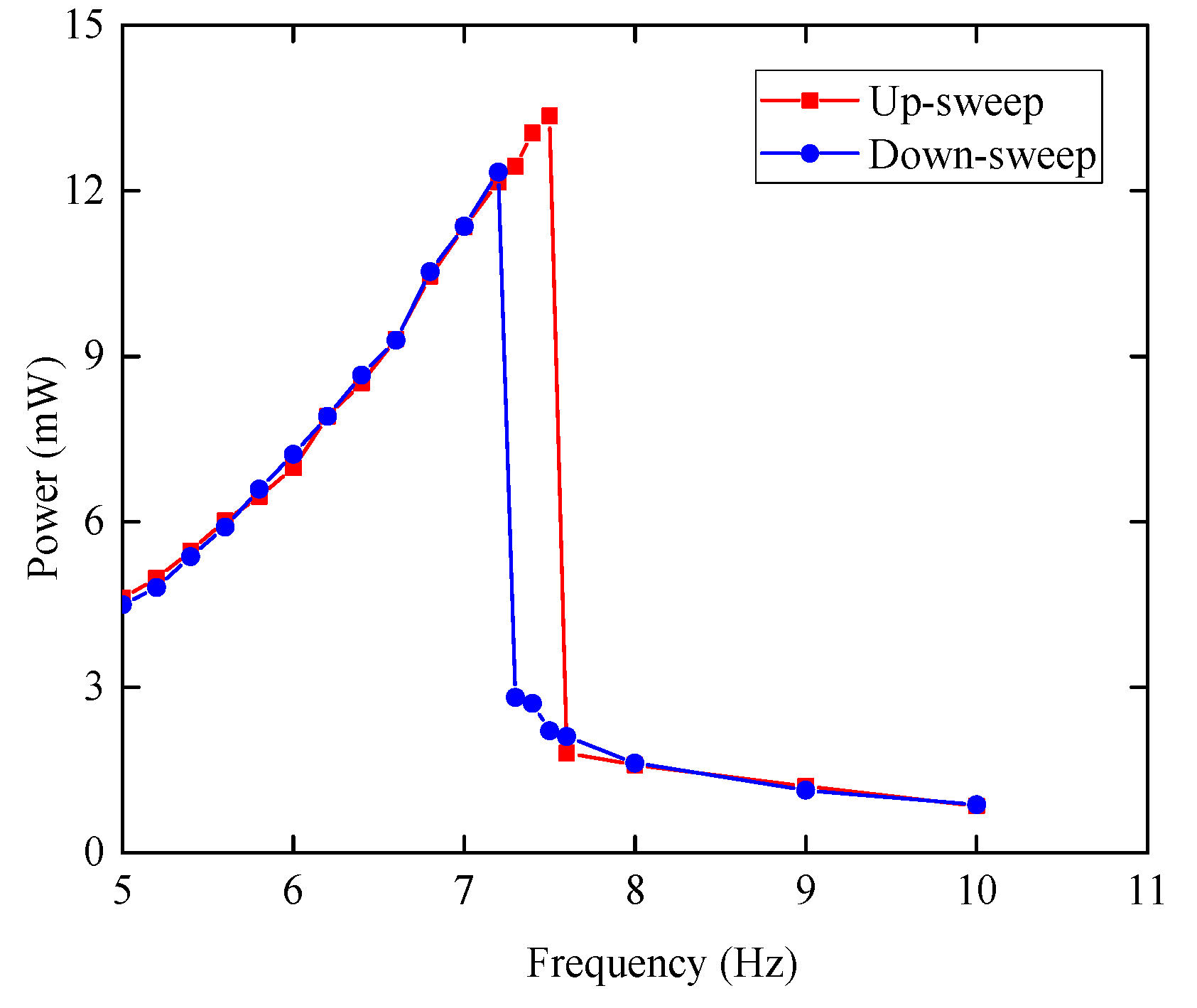
Under the base excitations with the acceleration amplitude of 0.2, the experimental up-sweep and down-sweep RMS voltages of VEH 1 across the 11 kΩ resistor are given in Figure 14. The maximum output powers of up-sweep and down-sweep are 13.3 and 12.1 mW at 7.5 and 7.2 Hz, respectively. The maximum output power and corresponding frequency of the up-sweep are about 12% and 4% higher than the down-sweep, respectively.
The performances of prototype VEH 1 are compared with some reported EMVEHs in Table 3. The output voltage and power of VEH 1 are the highest. Its power density is the second highest, lower than the EMVEH in [30], resulting from the relatively low acceleration amplitude of base excitation. The power density of the harvester developed by Haroun et al. is high [31]. As the resistance of their coil is only 1.8 Ω, the RMS output voltage is very low, about 12 mV. Their experiments show that, when the resistance increased to 2.38 Ω by using coil with more turns, the output voltage increased but the power density decreased. Therefore, the power density does not always increase with the turns of the coil. Owing to the optimized configuration and the large number of the turns of the coils, the output voltage of VEH 1 is the highest, and its power density is also comparable with those reported in literatures.
4.3. A Self-Powered Wireless Sensor Node
A wireless temperature and humidity sensor node powered by VEH 1, similar to the wireless temperature sensor node powered by a piezoelectric wind energy harvester [34], was developed. Since the output voltage of the proposed EMVEH is high enough, the power management circuit without a voltage boosting element, which has developed for a piezoelectric harvester [34], was used directly here. The power management module is composed of LTC3588-1 and LT3009, and MSP430 and nRF24L01 are selected as the processing core and the main transceiver. The temperature sensor TMP102 was replaced by the temperature and humidity sensor of SHT11, and the capacitor of 2200 μF was replaced by one of 10,000 μF.
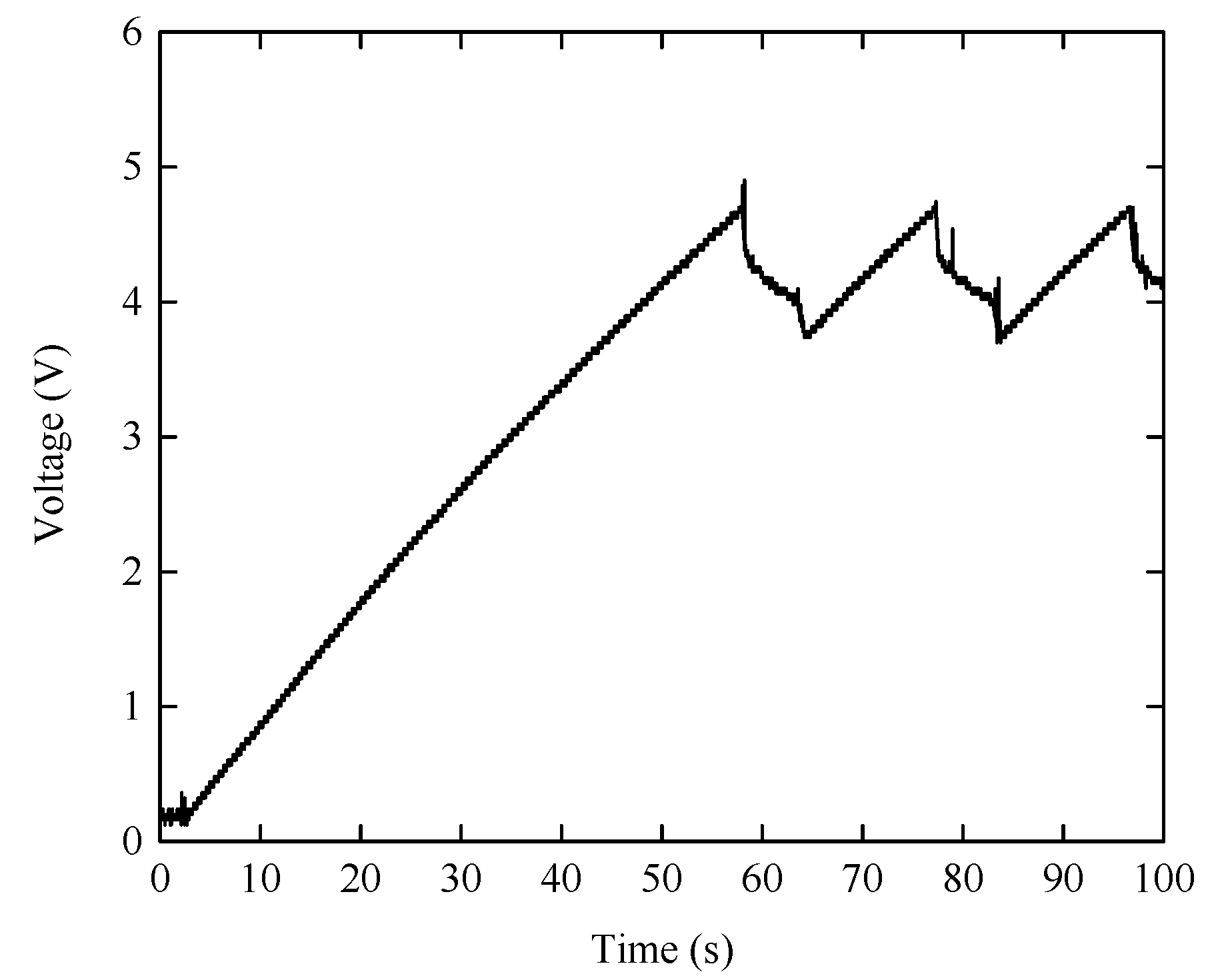
The prototype VEH 1 was used to power the wireless temperature and humidity sensor node, as shown in Figure 15. For the self-powered wireless sensor node, the temperature and humidity were transmitted by the nRF24L01 transceiver to a computer. As the impedance of the power management circuit is different from the harvester’s optimal load (11 kΩ), the frequency corresponding to the shortest charging times is about 5.4 Hz, which is different from the frequency at which the output powers across the optimal resistance reaches maximum value (as shown in Figure 13). Under base excitation with the amplitude of 0.1 at 5.4 Hz, the voltages on the capacitor are given in Figure 16. It took about 58 s for the harvester to charge the capacitor from 0 to 4.6 V. As soon as the capacitor reached the upper threshold voltage of 4.6 V, the node was powered on and started measuring the temperature and humidity, and then sent the results to the computer. When the voltage across the capacitor is higher than 3.6 V, the wireless sensor node was set to measure and transmit the temperature and humidity every 2 s. With the consumption of the electrical energy stored in the capacitor, the voltage across the capacitor decreased, before the voltage decreased to the lower threshold voltage of 3.6 V, the node can steady work for 8 s. After that, the node was switched off, and the capacitor was recharged. It took about 12 s for the harvester to charge the capacitor from 3.6 to 4.6 V again. Therefore, the wireless sensor node can measure and transmit the temperature and humidity every 20 s. The energy consumption for one operation is about 4.9 mJ. When the voltage decreases from 4.6 V to 3.6 V, the capacitor releases electrical energy of about 41 mJ, which are much higher than the requirements of the wireless sensor node. In the future, other sensors, such as pressure sensors, will be added into the node.
5. Conclusions
A non-resonant EMVEH with a high output voltage based on the mechanical impact was proposed to scavenge low-level, broadband, and low-frequency vibration energy in natural environments. Numerical simulations and experiments show that the scavenging efficiency of low-frequency vibration energy can be improved by increasing initial gap or decreasing the stiffness of the springs. Under base excitation with the acceleration amplitude of 0.3 at 8.5 Hz, the maximum output power of the prototype (VEH 1) is about 24.8 mW, with the power density of about 256 μW cm−3. By using a power management circuit without a voltage boosting element, it took about 58 s to use this prototype to charge a capacitor of 10,000 μF from 0 to 4.6 V under a base excitation of 0.1 at 5.4 Hz. A wireless sensor node powered by the prototype can measure and transmit the temperature and humidity every 20 s.
Acknowledgments
This work was financially supported by the National Natural Science Foundation of China (nos. 61376116 and 61774026) and the Cultivation Fund of the Key Scientific and Technical Innovation Project of Ministry of Education of China (no. 708072).
Author Contributions
Xuefeng He and Qian Luo proposed the idea. Qian Luo simulated and fabricated the harvester. Qian Luo, Senlin Jiang, and Xingchang Wang performed the experiments. All the authors took part in the discussions about the experimental results. The entire research project was conceived and supervised by Xuefeng He. All the authors were involved in preparing the manuscript.
Conflicts of Interest
The authors declare no conflict of interest.
References
- Paradiso, J.A.; Starner, T. Energy scavenging for mobile and wireless electronics. IEEE Pervasive Comput. 2005, 4, 18–27. [Google Scholar] [CrossRef]
- Roundy, S.; Wright, P.K. A piezoelectric vibration based generator for wireless electronics. Smart Mater. Struct. 2004, 13, 1131–1142. [Google Scholar] [CrossRef]
- Roundy, S.; Wright, P.K.; Rabaey, J. A study of low level vibrations as a power source for wireless sensor nodes. Comput. Commun. 2003, 26, 1131–1144. [Google Scholar] [CrossRef]
- Najafi, K.; Galchev, T.; Aktakka, E.E.; Peterson, R.L.; McCullagh, J. Microsystems for energy harvesting. In Proceedings of the 16th International Conference on Solid-State Sensors, Actuators and Microsystems, Transducers’11, Beijing, China, 5–9 November 2011; pp. 1845–1850. [Google Scholar]
- Khan, F.U. Review of non-resonant vibration based energy harvesters for wireless sensor nodes. J. Renew. Sustain. Energy 2016, 8, 044702. [Google Scholar] [CrossRef]
- Daqaq, M.F.; Masana, R.; Erturk, A.; Quinn, D.D. On the role of nonlinearities in vibratory energy harvesting: A critical review and discussion. Appl. Mech. Rev. 2014, 66, 040801. [Google Scholar] [CrossRef]
- Ferrari, M.; Ferrari, V.; Guizzetti, M.; Andò, B.; Baglio, S.; Trigona, C. Improvedenergy harvesting from wideband vibrations by nonlinear piezoelectricconverters. Sens. Actuators A Phys. 2010, 162, 425–431. [Google Scholar] [CrossRef]
- Kulah, H.; Najafi, K. Energy scavenging from low-frequency vibrations by using frequency up-conversion for wireless sensor applications. IEEE Sens. J. 2008, 8, 261–268. [Google Scholar] [CrossRef]
- Moss, S.; Barry, A.; Powlesland, I.; Galea, S.; Carman, G.P. A low profile vibro-impacting energy harvester with symmetrical stops. Appl. Phys. Lett. 2010, 97, 234101. [Google Scholar] [CrossRef]
- Galchev, T.V.; McCullagh, J.; Peterson, R.L.; Najafi, K. Harvesting traffic-induced vibrations for structural health monitoring of bridges. J. Micromech. Microeng. 2011, 21, 104005. [Google Scholar] [CrossRef]
- Gu, L.; Livermore, C. Impact-driven, frequency up-converting coupled vibration energy harvesting device for low frequency operation. Smart Mater. Struct. 2011, 20, 045004. [Google Scholar] [CrossRef]
- Halim, M.A.; Cho, H.; Salauddin, M.; Park, J.Y. A miniaturized electromagnetic vibration energy harvester using flux-guided magnet stacks for human-body-induced motion. Sens. Actuators A Phys. 2016, 249, 23–31. [Google Scholar] [CrossRef]
- Haroun, A.; Yamada, I.; Warisawa, S. Study of electromagnetic vibration energy harvesting with free/impact motion for low frequency operation. J. Sound Vib. 2015, 349, 389–402. [Google Scholar] [CrossRef]
- Renaud, M.; Fiorini, P.; van Schaijk, R.; van Hoof, C. Harvesting energy from the motion of human limbs: The design and analysis of an impact-based piezoelectric generator. Smart Mater. Struct. 2009, 18, 035001. [Google Scholar] [CrossRef]
- He, X.F.; Teh, K.S.; Li, S.Y.; Dong, L.X.; Jiang, S.L. Modeling and experimental verification of an impact-based piezoelectric vibration energy harvester with a rolling proof mass. Sens. Actuators A Phys. 2017, 259, 171–179. [Google Scholar] [CrossRef]
- Zhang, H.J.; Jiang, S.L.; He, X.F. Impact-based piezoelectric energy harvester for multidimensional, low-level, broadband and low-frequency vibration. Appl. Phys. Lett. 2017, 110, 223902. [Google Scholar] [CrossRef]
- Beeby, S.P.; Torah, R.N.; Tudor, M.J.; Glynne-Jones, P.; O’Donnell, T.; Saha, C.R.; Roy, S. A micro electromagnetic generator for vibration energy harvesting. J. Micromech. Microeng. 2007, 17, 1257–1265. [Google Scholar] [CrossRef]
- Wang, P.H.; Tanaka, K.; Sugiyama, S.; Dai, X.H.; Zhao, X.L.; Liu, J.Q. A micro electromagnetic low level vibration energy harvester based on MEMS technology. Microsyst. Technol. 2009, 15, 941–951. [Google Scholar] [CrossRef]
- Elfrink, R.; Kamel, T.M.; Goedbloed, M.; Matova, S.; Hohlfeld, D.; van Andel, Y.; van Schaijk, R.J. Vibration energy harvesting with aluminum nitride-based piezoelectric devices. Micromech. Microeng. 2009, 19, 094005. [Google Scholar] [CrossRef]
- Feng, Y.-Y.; Chen, S.-J.; Tu, Y.-L. Development of a vibration-based electromagnetic energy harvester by a conductive direct-write process. Energies 2017, 10, 337. [Google Scholar] [CrossRef]
- Roundy, S.; Leland, E.S.; Baker, J.; Carleton, E.; Reilly, E.; Lai, E.; Otis, B.; Rabaey, J.M.; Wright, P.K.; Sundararajan, V. Improving power output for vibration-based energy scavengers. IEEE Pervasive Comput. 2005, 4, 28–36. [Google Scholar] [CrossRef]
- He, X.F.; Shang, Z.G.; Cheng, Y.Q.; Zhu, Y. A micromachined low-frequency piezoelectric harvester for vibration and wind energy scavenging. J. Micromech. Microeng. 2013, 23, 125009. [Google Scholar] [CrossRef]
- Hoffmann, D.; Folkmer, B.; Manoli, Y. Fabrication, characterization and modelling of electrostatic micro-generators. J. Micromech. Microeng. 2009, 19, 094001. [Google Scholar] [CrossRef]
- Suzuki, Y.; Miki, D.; Edamoto, M.; Honzumi, M. A MEMS electret generator with electrostatic levitation for vibration-driven energy-harvesting applications. J. Micromech. Microeng. 2010, 20, 104002. [Google Scholar] [CrossRef]
- Bendame, M.; Abdel-Rahman, E.; Soliman, M. Wideband, low-frequency springless vibration energy harvesters: Part I. J. Micromech. Microeng. 2016, 26, 115021. [Google Scholar] [CrossRef]
- Beeby, S.P.; O’Donnell, T. Electromagnetic energy harvesting. In Energy Harvesting Technologies, 1st ed.; Priya, S., Inman, D.J., Eds.; Springer: New York, NY, USA, 2009; pp. 130–132. [Google Scholar]
- The Engineering ToolBox. Available online: http://www.engineeringtoolbox.com/rolling-friction-resistance-d1303.html (accessed on 8 June 2017).
- Ashraf, K.; Khir, M.H.; Dennis, J.O. Improved energy harvesting from low frequency vibrations by resonance amplification at multiple frequencies. Sens. Actuators A Phys. 2013, 195, 123–132. [Google Scholar] [CrossRef]
- MITCalc. Available online: http://www.mitcalc.com/doc/springs/help/en/springs.html (accessed on 10 July 2017).
- Ashraf, K.; Khir, M.H.M.; Dennis, J.O.; Baharudin, Z. A wideband, frequency up-converting bounded vibration energy harvester for a low-frequency environment. Smart Mater. Struct. 2013, 22, 049601. [Google Scholar] [CrossRef]
- Haroun, A.; Yamada, I.; Warisawa, S. Micro electromagnetic vibration energy harvester based on free/impact motion for low frequency-large amplitude operation. Sens. Actuators A Phys. 2015, 224, 87–98. [Google Scholar] [CrossRef]
- Lee, B.C.; Chung, G.S. Design and fabrication of low frequency driven energy harvester using electromagnetic conversion. Trans. Electr. Electron. Mater. 2013, 14, 143–147. [Google Scholar] [CrossRef]
- Jo, S.E.; Kim, M.S.; Kim, Y.J. Electromagnetic human vibration energy harvester comprising planar coils. Electron. Lett. 2012, 48, 874–875. [Google Scholar] [CrossRef]
- Zhang, C.; He, X.F.; Li, S.Y.; Cheng, Y.Q.; Rao, Y. A wind energy powered wireless temperature sensor node. Sensors 2015, 15, 5020–5031. [Google Scholar] [CrossRef] [PubMed]
Figure 1.
Schematic of an impact-based electromagnetic kinetic energy harvester: (a) freely movable; (b) left springs being compressed; and (c) right springs being compressed.
Figure 1.
Schematic of an impact-based electromagnetic kinetic energy harvester: (a) freely movable; (b) left springs being compressed; and (c) right springs being compressed.

Figure 2.
Model of the impact-based kinetic energy harvester.

Figure 3.
The distribution of the magnetic flux density.

Figure 4.
The schematic of the coil in the magnetic field.

Figure 5.
The rate of change of total flux versus the relative displacement.

Figure 6.
Effects of spring stiffness on RMS voltages under the base excitation of 0.2.

Figure 7.
Effects of initial gaps on RMS voltages under base excitation of 0.2.

Figure 8.
Photographs of a prototype harvester.

Figure 9.
Experimental setup.

Figure 10.
Output power versus load resistance under different base excitations.

Figure 11.
Output performances of VEHs under base excitation of 0.3: (a) output RMS voltage; and (b) output power.
Figure 11.
Output performances of VEHs under base excitation of 0.3: (a) output RMS voltage; and (b) output power.

Figure 12.
Time histories of voltages at different excitation frequencies: (a) 5.5 Hz; (b) 8.5 Hz; and (c) 10 Hz.
Figure 12.
Time histories of voltages at different excitation frequencies: (a) 5.5 Hz; (b) 8.5 Hz; and (c) 10 Hz.

Figure 13.
RMS voltage versus excitation frequency.

Figure 14.
Output power versus excitation frequency with up-sweep and down-sweep.

Figure 15.
Photograph of the application experiments.

Figure 16.
Voltage across the capacitor under base excitation of 0.1 at 5.4 Hz.


Table 1.
Parameters of the harvester in simulations.
| Parameter | Value |
|---|---|
| Magnetization of Magnets | 750 kA/m [28] |
| Separation between magnet rows | 7 mm |
| Magnet dimension | 20 mm × 10 mm × 4 mm |
| Coil dimension | 18 mm × 9 mm × 3 mm |
| Dimension of the coil through-hole | 12 mm × 3 mm × 3 mm |
| Diameter of the wire | 0.05 mm |
| Number of coil turns | 2500 |
| Coil resistance | 800 Ω |
| Mass of the inner frame | 0.1 kg |
| Viscous damping coefficient | 0.68 [25] |
| Damping coefficient of springs | 0.68 |
Table 2.
Parameters of the prototypes.
| Prototypes | Initial Gap S (mm) | Spring Stiffness K (N/m) |
|---|---|---|
| VEH 1 | 1.5 | 380 |
| VEH 2 | 2.5 | 380 |
| VEH 3 | 2.5 | 1220 |
Table 3.
Comparison between some reported electromagnetic vibrational energy harvesters (EMVEHs) and this work.
Table 3.
Comparison between some reported electromagnetic vibrational energy harvesters (EMVEHs) and this work.
| Reference | Amplitude (m s2) | Frequency (Hz) | Volume (cm3) | Voltage (V) | Power (μW) | Power Density (μW cm−3) |
|---|---|---|---|---|---|---|
| Galchez 2011 [10] | 0.54 | 2 | 43 | 0.059 | 2.3 | 0.0535 |
| Ashraf 2015 [30] | 9.8 | 18 | 27.38 | 1.44 | 9360 | 342 |
| Haroun 2015 [31] | 12.38 | 3.33 | 0.461 | 0.012 | 82.9 | 180 |
| Lee 2013 [32] | 1.96 | 8 | 21 | 0.28 | 65.3 | 3.1 |
| Jo 2012 [33] | 2.5 | 8 | 10 | - | 430 | 43 |
| VEH 1 | 3 | 8.5 | 97 | 16.5 | 24,800 | 256 |
© 2017 by the authors. Licensee MDPI, Basel, Switzerland. This article is an open access article distributed under the terms and conditions of the Creative Commons Attribution (CC BY) license (http://creativecommons.org/licenses/by/4.0/).
Share and Cite
MDPI and ACS Style
Luo, Q.; He, X.; Jiang, S.; Wang, X. Impact-Based Electromagnetic Energy Harvester with High Output Voltage under Low-Level Excitations. Energies 2017, 10, 1848. https://doi.org/10.3390/en10111848
AMA Style
Luo Q, He X, Jiang S, Wang X. Impact-Based Electromagnetic Energy Harvester with High Output Voltage under Low-Level Excitations. Energies. 2017; 10(11):1848. https://doi.org/10.3390/en10111848
Chicago/Turabian StyleLuo, Qian, Xuefeng He, Senlin Jiang, and Xingchang Wang. 2017. "Impact-Based Electromagnetic Energy Harvester with High Output Voltage under Low-Level Excitations" Energies 10, no. 11: 1848. https://doi.org/10.3390/en10111848
Note that from the first issue of 2016, this journal uses article numbers instead of page numbers. See further details here.