A Review of Design Optimization Methods for Electrical Machines


1
School of Electrical and Data Engineering, University of Technology Sydney, Ultimo 2007, Australia
2
State Key Laboratory of Reliability and Intelligence of Electrical Equipment, Hebei University of Technology, Tianjin 300131, China
*
Author to whom correspondence should be addressed.
Energies 2017, 10(12), 1962; https://doi.org/10.3390/en10121962
Submission received: 30 September 2017
/
Revised: 21 November 2017
/
Accepted: 22 November 2017
/
Published: 24 November 2017
(This article belongs to the Section I: Energy Fundamentals and Conversion)
Abstract
:Electrical machines are the hearts of many appliances, industrial equipment and systems. In the context of global sustainability, they must fulfill various requirements, not only physically and technologically but also environmentally. Therefore, their design optimization process becomes more and more complex as more engineering disciplines/domains and constraints are involved, such as electromagnetics, structural mechanics and heat transfer. This paper aims to present a review of the design optimization methods for electrical machines, including design analysis methods and models, optimization models, algorithms and methods/strategies. Several efficient optimization methods/strategies are highlighted with comments, including surrogate-model based and multi-level optimization methods. In addition, two promising and challenging topics in both academic and industrial communities are discussed, and two novel optimization methods are introduced for advanced design optimization of electrical machines. First, a system-level design optimization method is introduced for the development of advanced electric drive systems. Second, a robust design optimization method based on the design for six-sigma technique is introduced for high-quality manufacturing of electrical machines in production. Meanwhile, a proposal is presented for the development of a robust design optimization service based on industrial big data and cloud computing services. Finally, five future directions are proposed, including smart design optimization method for future intelligent design and production of electrical machines.
1. Introduction
1.1. Energy and Environmental Challenges
Electrical machines, as the main drive sources, have been widely employed from industry to agriculture, from defence to community facilities, from domestic appliance to electronic products, etc. They are the foundation of the power industry and the core components of industrial machinery. Electrical machines consume about 46% of total electricity generated worldwide, resulting in about 6040 Mega-tonnes of CO2 emission. This is the largest portion of electricity use up to now, as shown in Figure 1. Therefore, motor energy efficiency is crucial for the energy conservation, environment protection, and global sustainable development. Consequentially, high-efficiency motors will dominate the market development of electrical machines worldwide [1,2,3].
Besides the energy efficiency, there are many other specifications and/or requirements for the design optimization of electrical machines, such as torque, power density, volume and weight. For special applications like geologic or petroleum drilling engineering and aerospace engineering, more requirements and extreme constraints should be investigated [4,5,6]. For example, the environment temperature for motors used in petroleum and geology may reach 300 °C, or even to 500 °C. The high surrounding temperature will result in severe performance degradation due to the increase of the copper loss and the demagnetization of permanent magnets (PM) for PM motors.
Thus, all performance specifications and requirements including energy efficiency are vital for the application of electrical machines. Consequently, improving motor performance is of great significance to both the environment protection and the energy sustainability. To achieve this goal, optimization is always necessary [2,7,8,9,10,11].
1.2. An Overview of Design and Optimization of Electrical Machines
Design optimization of electrical machines includes two main stages, design and optimization. The main aim of the design stage is to find a feasible scheme (or several schemes) for a given application through the investigation of different materials and dimensions, motor types and topologies, multi-disciplinary analysis including electromagnetic analysis, and/or design experience. The analysis of this stage will provide information including motor parameter calculation and performance evaluation for the development of optimization model that will be used in the next stage. The main target of optimization stage is to improve the performance of the motor proposed in the design stage through some optimization algorithms and methods. As the outcome, an optimal solution will be obtained for the single objective design situation, and some non-dominated solutions (called Pareto optimal solutions) will be gained for the multi-objective design situation after the completion of this stage. Figure 2 illustrates a brief framework for the main aspects covered in the design and optimization of electrical machines.
There is no fixed procedure for the design optimization of electrical machines. However, there are some common steps to be followed. These steps are briefly described as follows. More details can be seen in the following sections:
Step 1: Select/determine possible motor types and topologies, materials and dimensions according to the requirements given by the applications and users. Requirements include steady-state and dynamic performances like efficiency, torque and torque ripple, material and manufacturing costs, volume and others. The main aim of this step is to obtain a number of motor options which may be suitable for a specific applications.
Step 2: Implement multi-physics design and analysis for each motor option. Due to the multi-physics nature, many disciplines have to be investigated in this step, such as electromagnetics, structural mechanics and heat transfer [2,12,13,14,15,16,17,18,19]. Moreover, power electronics and control should be included as they are relevant to the dynamic responses of the machines, such as overshoot and settling time [20,21,22,23]. This step targets to calculate some parameters for the evaluation of motor performance, including electromagnetic parameters like core loss, inductance and back electromotive force (EMF), and thermal parameters like temperature rise and distribution.
Step 3: Evaluate motor performance for each option, including output power or torque, efficiency and cost. Based on the evaluation and comparison, one or several feasible designs can be gained.
Step 4: Develop optimization models based on those feasible designs. For each design, detailed optimization objective(s), constraints, parameters and their types like discrete or continuous should be defined in the optimization model. Considering the manufacturing quality of the electrical machines in practical production, robust optimization model can be developed to replace the conventional deterministic optimization model [2].
Step 5: Optimize those optimization models and obtain an optimal solution or some optimal solutions. The implementation covers optimization algorithms and methods. For optimization algorithms, there are two main types, classic and modern intelligent algorithms. Regarding the optimization methods or strategies, there are many options as well, such as multi-level and multi-disciplinary [2,7,24,25,26,27,28,29,30,31,32,33,34,35]. After the optimization, compare all optimal designs and output the best one with detailed design scheme and the simulated performances.
Step 6: Validate the design with a prototype and experiment results. If the experimental results are well aligned with simulated results, the employed models and methods like finite element model (FEM) used in the design step have good accuracy. If not, modifications should be applied to those design analysis models. Then another optimization should be conducted, and a new prototype should be built to verify the proposed design.
This paper aims to present a state-of-art and a discussion on the challenges and future directions of the design optimization methods for electrical machines. It is organized as follows. Section 2 presents a brief review of the design analysis methods and models for electrical machines. Section 3 provides an overview of the popular models used in the optimization of electrical machines. Section 4 reviews the classic and modern intelligent optimization algorithms. Section 5 highlights the popular optimization methods and some novel optimization methods for improving the optimization efficiency, including surrogate models based method and multi-level method. Section 2, Section 3, Section 4 and Section 5 present details and discussion for Figure 2. Section 6 discusses two challenges in this field and proposes several novel optimization methods, including system-level optimization method and robust design optimization method, and the robust design optimization service based on the industrial big data and cloud computing technology, for electrical machines. Several case studies are provided in Section 5 and Section 6 to show more details and discussions for multi-level and robust optimization methods. Section 7 concludes the paper and proposes five promising future directions.
2. Design Analysis of Electrical Machines
Electrical machines have over one hundred years of history. There are many types and classifications, such as DC and AC machines, rotating and linear machines, synchronous and asynchronous/induction machines, and PM and superconducting machines. Each one may have some specific design principles. Meanwhile, there are some general design methods, which can be sketched in terms of different disciplines/domains.
2.1. Electromagnetic Design
The principle of operation of electrical machines is based on the electromagnetic theory. Therefore, electromagnetic design is critical. This design aims to compute some basic electromagnetic parameters including winding inductance through the calculation of magnetic field and its distribution in the electrical machines, and to evaluate the performances, such as electromagnetic force, power loss and efficiency based on them. To obtain the magnetic field, there are three main kinds of analysis methods, analytical method, magnetic circuit method and finite element method [2,12,13,36,37,38,39,40,41].
Meanwhile, power losses and efficiency are two important performance indexes for electrical machines. The power losses mainly consist of the copper loss, core loss, mechanical loss, and stray loss. For the estimation of mechanical losses and stray loss, empirical data can be employed. For example, the stray loss can be assumed to be 1% of the output power for most types of machines. The efficiency of an electrical machine can be calculated based on these losses.
2.2. Thermal Design and Structural Design
Thermal design and structural design can be conducted after the completion of the electromagnetic design. For the thermal design, the main aim is to calculate the temperature distribution in the machine based on the heat obtained from the electromagnetic analysis. There are two popular methods for the thermal analysis of electrical machines. They are thermal network method and finite element method [12,13,16,42,43,44].
Structural design aims to consider the stress and deformation of the machine under the electromagnetic and thermal analyses. Meanwhile, modal analysis for vibration and noise investigation requires special attention for some situations including high-speed application. Structural design can be conducted based on finite element method as well [18,19].
2.3. Multi-Physics Design
Multi-physics design aims to calculate the electromagnetic characteristics, temperature distribution, structural stress, vibration noise and coupled performances of electrical machines based on a uniform model [2,12,13,16]. With the development of the CAE software, finite element method has been widely employed as a powerful tool for the multi-physics design and analysis of electrical machines. It can be used to analyze the coupled field in machines, such as electromagnetic-thermal, electromagnetic- structure and thermal-structure.
2.4. Material Design
Material is crucial for the electromagnetic, thermal and structural designs of electrical machines. Besides the widely used material like steel sheet, some newly developed magnetic materials like soft magnetic composite (SMC), amorphous and grain-oriented silicon steel show better characteristics, such as high saturation flux density, low specific losses, and low manufacturing cost [45,46,47,48,49,50]. They can be employed to design motors with new topologies, higher efficiency and/or low manufacturing cost.
2.5. Manufacturing Process Design
Manufacturing method and process design are also important in the design stage of electrical machines, which will influence their manufacturing quality and actual performances in operation. For example, to obtain the best performances, some designs may have complex structures which may be difficult for manufacturing. For another example, the magnetic and mechanical properties of some new materials, such as SMC and amorphous, are highly dependent on the manufacturing method. Without a good knowledge of the magnetic characteristics and manufacturing methods, the performances of the designed motors are able to provide cannot be fully exploited [51,52,53,54].
Produced from iron powders with coated insulating layer, SMC has isotropic magnetic and thermal properties and low eddy current loss. Hence, it possesses a promising application for the cores of 3D flux machines, such as claw pole motor (CPM) and transverse flux machine (TFM). Meanwhile, SMC core can be manufactured by using moulding technology in the production environment. Therefore, SMC is superior to traditional steel sheets for the design of CPM and TFM in terms of magnetic performance and manufacturing cost in production [2]. For amorphous material, it has low loss magnetic properties in motor application. However, as a very brittle material, its mechanical characteristics highly depend on the manufacturing process. To make full use of this kind of material in the motor design, special attention should be paid to the design of new motor topologies and manufacturing process [49,50]. Thus, a good motor design should be good in terms of both output performances and manufacturing abilities.
As one of the two stages in the design optimization of electrical machines, the developed analysis methods and models in this design stage will be employed to develop optimization models for the next stage.
3. Optimization Models of Electrical Machines
There are several types of the optimization models of electrical machines. Regarding the numbers of objectives, there are single and multi-objective models. From the perspective of the manufacturing quality, there are deterministic and robust optimization models.
3.1. Single and Multi-Objective Optimization Models
Considering a single-objective optimization problem with m constraints, its optimization model can be expressed as:
where x, f and g are the design parameter vector, objectives and constraints, xl and xu the lower and upper boundaries of x, respectively. Popular objectives are maximizing the efficiency, force, torque, and output power or power density, and minimizing cogging torque, torque ripple, and weight and volume. Popular constraints are the current density in the winding, temperature rise, supplied voltage, and weight and volume. Optimization parameters mainly include dimension and material, such as dimensions of PMs, stator and rotor, length of air gap, number of turns and diameter of winding, and material characteristics like PM remanence and density of SMC core.
Similarly, the optimization model of a multi-objective design problem with p objectives and m constraints has the form:
The objectives in (2) are always conflicting due to the nature of multi-objective optimization. Thus, the optimal solutions of (2) are actually a compromise between these objectives, which are non-inferior solutions theoretically and can be called as Pareto solutions.
3.2. Deterministic and Robust Optimization Models
From the perspective of industrial design and manufacturing, the design optimization models (1) and (2) are deterministic because they have not investigated the variations of parameters. There are many unavoidable manufacturing variations/uncertainties in the practical production process of electrical machines. Three main types are manufacturing tolerances, material diversities and assembling inaccuracy. Table 1 lists variations for some factors of PM motors. As shown, there are many manufacturing uncertainties for the PMs, including dimension and strength, which will result in big performance variations for the PMs as well as the motors, such as cogging torque and back EMF [2,55,56,57,58,59,60]. Hence, these manufacturing variations/uncertainties strongly impact the practical manufacturing quality of an electrical machine or production quality of a batch of motors. An extremely optimized design (without consideration of practical process design and manufacturing quality) may be not producible because of high manufacturing cost and/or high defective rates. To decrease the reject rates (or increase the manufacturing reliability) of electrical machines, robust design optimization is always a necessity.
Figure 3 shows the comparison between deterministic and robust optimization methods. As shown, there are two points A and B, which can be regarded as optimums obtained from deterministic and robust methods respectively. Deterministic method tends to find the global optimum (point A) of a function f(x) without any consideration of parameter variations. This may results in big fluctuations (∆f1) of the objective when there are variations (±∆x) for a parameter, for example, the width of a PM. Some designs become unacceptable as objectives fall into the infeasible domain. Thus, design A offers inferior robustness compared with design B though B is a local minimum.
To evaluate the robustness of a design, new criteria are required, such as gradient index, mean and standard deviation of the objectives and constraints. Two popular design optimization methods are Taguchi method and the design for six-sigma (DFSS) method [61,62,63,64,65,66,67,68]. However, as robust design optimization is a challenging topic for electrical machines, we do not plan to present too many details here. More details will be discussed in Section 6.
3.3. Comparison Between Design and Optimization Models
In general, optimization models are developed based on the design models, for example, FEM. In detail, there are three main aspects of the optimization models, objectives, constraints and parameters. They are related to the design methods and models discussed in Section 2.
First, objectives and constraints can be developed based on the analysis models employed in the design stage. Take the optimization of a PM motor as an example. Assume the objective is to maximize the efficiency, and constraints are output power, the temperature rise in winding and resonance frequency in operation. To evaluate them, several models of electromagnetic, structural and thermal filed are required. For instance, if magnetic circuit model is employed as the electromagnetic design analysis model, then electromagnetic parameters such as back EMF and inductance can be calculated for the motor. Based on them and some assumptions (for example, the stray loss is 1% of the output power), motor efficiency, output power and/or torque can be estimated. Then if thermal network model is used to calculate the winding temperature rise, and FEM is employed to compute the resonance frequency. These three models will be used in the optimization to evaluate the objectives f(x) and constraints gi(x) for each candidate in the population of an algorithm.
For the optimization parameters, theoretically, all material parameters and dimensions used in the design stage can be investigated in the optimization, such as remanence, length, width and height of PMs, radiuses of rotor and stator, number of turns of winding and the length of the air gap. For each parameter, it includes range and type like integer, discrete and continuous. For example, the number of turns of winding should be an integer. Some parameters can be regarded as continuous theoretically, such as PM and stator radius. However, due to the manufacturing tolerances, all of them should be taken as discrete in the practical design. In the optimization, we can use step size to differentiate them. For example, 1 is the step size for the number of turns of winding, and 0.05 mm is the step size of PM length or rotor radius [2]. By using the step sizes, manufacturing factors can be considered in the optimization as well because different manufacturing processes possess different tolerances. In brief, all design analysis methods, models and experience can be linked to the optimization, and they are helpful for the development of optimization models.
4. Optimization Algorithms for Electrical Machines
4.1. Popular Algorithms
Based on the development of the optimization models (1) and (2), optimization algorithms can find the optimal results. Figure 4 shows some popular optimization algorithms for the design optimization of electrical machines as well as other electromagnetic devices. As shown, there are two main types, gradient-based algorithms and intelligent optimization algorithms.
Conjugate based algorithms, such as conjugate gradient algorithms and their nonlinear versions, are simple in implementation. For example, they can be employed to optimize (1) with motor performances estimated based on magnetic circuit model [69,70,71]. Meanwhile, there are constraints to apply these algorithms, for example, analytical expressions for the objective functions and constraints. However, nowadays, many analysis models for electrical machines are based on FEM instead of the analytical model and equivalent circuit model. Therefore, intelligent optimization algorithms have been employed for the optimization of electrical machines in the past several decades, such as the evolutionary algorithms (EAs), particle swarm optimization (PSO) algorithms, estimation of distribution algorithms (EDAs), immune algorithm, and ant colony algorithm, and their improvements [72,73,74,75,76]. For the widely used genetic algorithm (GA) and differential evolution algorithms (DEAs), they are two of four major subclasses of EAs. The other two subclasses are evolution programming and evolution strategy.
Multi-objective optimization has become popular in this field nowadays, as design optimization of electrical machines is multi-objective in nature, such as maximizing the torque and minimizing the torque ripple, and maximizing the power density and minimizing active material cost. To solve this kind of optimization problem, multi-objective optimization algorithms are required. They can provide a Pareto solution set with a single run. This solution set consists of many non-dominated optimal design solutions for the designer to select based on a specific application (meaning specific weighting factors). Some popular multi-objective optimization algorithms are originated from GA and PSO, such as multi-objective GA, non-dominated sorting GA (NSGA) and its improvements (NSGA II), and multi-objective PSO algorithm [77,78,79,80,81,82,83].
4.2. Comparison and Comments
Different from conventional gradient-based algorithms, the implementation of intelligent optimization algorithms does not depend on the mathematical properties of the optimization models. For example, the functions of objectives are not required to be continuous and differentiable, and to have analytical expressions. Compared with conventional ones, intelligent optimization algorithms have many advantages, such as global optimizing, stronger robustness and parallel searching capability.
There are three main steps in the implementation of intelligent optimization algorithms. They are population initialization and algorithm parameter determination, individual updating and population regeneration. Different algorithms have different algorithm parameters and strategies for individual updating and population regeneration. For the comparison and ranking between different intelligent algorithms, there are some results in the field of evolutionary computation. It is found that DEAs perform better than others for most employed benchmark problems, indicating good potential for design optimization problems of electrical machines [7,72]. However, from an engineering point of view, these ranking are not truly appropriate because the performance is a problem- and case-dependent and most intelligent algorithms are satisfying in all cases [72]. Based on the experience of the authors, no significant differences have been found when optimizing electrical machines with different kinds of intelligent optimization algorithms. However, we found that the optimization methods or strategies are more important because they are key for the improvement of optimization efficiency. Therefore, several optimization methods/strategies will be discussed in the next session. We believe they should deserve more attention.
5. Optimization Methods/Strategies for Electrical Machines
5.1. Common Practice and Issues
With the optimization models and optimization algorithms developed in Section 3 and Section 4, an optimization can be implemented with an optimization method or strategy. There are many types of optimization methods/strategies, and several popular ones are:
- (a)
- Direct (design model based) optimization method
- (b)
- (c)
- (d)
- (e)
Conventional direct optimization method employs design analysis models (such as FEM and thermal network model) to evaluate the objectives and constraints in the model (1) or (2), and optimizes all parameters at once by using an optimization algorithm like GA. This method is simple in implementation. For example, it can be realized by integrating MATLAB and ANSYS, i.e., using MATLAB to call the ANSYS code in the optimization program. As FEM is widely used nowadays in the design analysis of electrical machines due to its high accuracy, the main issue of this method is the computation cost. For example, consider a PM motor with 10 parameters for optimization by using the GA. Around 10,000 (=10 × 5 × 200) evaluations of the optimization model are required, where 200 is an approximate iteration number for convergence, 10 × 5 is a general population size in each iteration (generation) of GA. If each evaluation consists of no-load and load finite element analyses, 20,000 FEM have to be simulated in the optimization. For a motor with 3D FEM, it may require half minute or more for one simulation, and then at least 10,000 min (around 166 h or 7 days) will be required to obtain an optimal solution. This is a huge computation burden for most designers.
To address this issue, some surrogate models like response surface model (RSM) and Kriging model have been developed and applied to the optimization of electrical machines. These surrogate models can be used replace the FEM required in the optimization implementation of (1) and (2). However, the design of experiment (DoE) technique is necessary to construct the surrogate models, which requires the FEM simulation as well. The following subsection reviews surrogate models and their construction techniques.
5.2. Surrogate Models, Modeling Techniques and Optimization
5.2.1. Surrogate Models
There are several types of surrogate models, such as RSM, Kriging model, radial basis function (RBF) model, support vector machine model, and artificial neural network model [55,56,57,58,59,60,61,62,63]. Meanwhile, some improvements have been developed form them in the last several decades, such as moving least square model (MLSM, an improvement of RSM) and compactly supported radial basis function model (an improvement of RBF model). All of them have been successfully employed for the optimization design of electromagnetic devices and systems including electrical machines. Three widely used ones, RSM, RBF and Kriging models, are compared in Table 2. In the equations, y is the response for an input x, are the n given samples, is a matrix of the responses of the samples, are matrixes of the basis functions, is a matrix of the correlation functions.
Mathematically, RSM and RBF are parametric models, while Kriging model is a semi-parametric model as it consists of two terms, deterministic term and stochastic process term. Compared with RSM and RBF model, Kriging is superior in the modelling of local nonlinearities [84].
Considering the modelling complexity, RBF is higher than RSM because there are extra shape parameters in the model basis functions in RBF while RSM does not have these parameters. Kriging model is the most complex one. As shown, not only the coefficient matrix in the deterministic term but also the parameters in the stochastic process term like variance and parameters in the correlation function have to be estimated in this kind of model. For this purpose, best linear unbiased estimation (BLUE) method is employed for estimation of β, and maximum likelihood estimation (MLE) method is used to estimate variance σ2. To effectively estimate these parameters, a software package called Design and Analysis of Computer Experiments (DACE) has been developed in MATLAB [85]. More details of these models and their applications can be found in references [2,7,87,88,89,90,91,92].
5.2.2. Modelling Techniques
To obtain an accurate surrogate model, modelling techniques are required to investigate. Normally, there are several steps for the development of a surrogate model, including generation of samples by using DoE techniques, model construction and verification [2,93,94,95,96]. Figure 5 illustrates the main steps, which are briefly summarized as follows.
Firstly, generate some samples by using a DoE technique. There are two main types of DoE techniques in Statistics, full factor design and partial factor design. Popular partial factor design includes Latin hypercube design, uniform design and orthogonal design.
Secondly, develop a kind of surrogate model based on the obtained samples. Table 2 lists the parameter estimation methods and solutions for RSM, RBF and Kriging models. More details can be found in reference [2]. Many DoE techniques and surrogate models have been integrated into the software, such as MATLAB, SPSS, and MINITAB.
Finally, to ensure that the constructed model is accurate, error analysis should be conducted based on some new and different samples. Several criteria may be applied for this purpose, such as root mean square error and mean relative error. If the model is with good accuracy, it can be used for the later optimization, and the obtained optimization results are reliable.
5.2.3. Comments
First, there are two ways for the implementation of surrogate models in the optimization. Assume the optimization objective is maximizing the motor efficiency () and FEM is employed as the electromagnetic analysis model to obtain parameters back EMF, winding inductance and core loss. The first way is to develop a surrogate model like RSM for the efficiency directly. The second way is to develop three surrogate models to replace the FEMs used for the evaluation of three electromagnetic parameters, back EMF, winding inductance and core loss. Then motor efficiency is calculated based on those three models. Though the required FEM samples are the same for the two ways, the latter always has higher accuracy than the former. The main reason is that all of them are nonlinear to the design parameters. The accumulated error is higher if we incorporate them in one function.
Second, as compared in Table 2, a Kriging model has better modelling capability of local nonlinearities while it is more complex compared with RSM and RBF. However, Kriging has attracted more attention recently as there are no significant differences in the computation speeds of these models in PCs and public toolbox is available.
Third, there are two main issues for the application of surrogate models. They are computation cost of DoE samples and model accuracy. Full factor DoE techniques have been used to increase the accuracy of the solution in many situations. However, they require a large amount of FEM simulation cost, especially for high-dimensional situations. For example, considering a PM motor with 5 parameters for optimization, 105 = 100,000 FEM samples are needed if a 10-level full factor DoE technique is applied, and 55 = 3125 FEM samples are needed if a 5-level full factor DoE technique is applied for the development of RSM or Kriging. The model with 10-level full factor DoE technique has higher accuracy than the 5-level one; however, the computation cost is a huge for most designers.
Therefore, optimization efficiency is a big issue for both direct and in-direct optimization methods. To attempt this issue, some new and efficient optimization methods are introduced as follows. The first one is a SOM based on a space reduction method, which is mainly proposed for the low-dimensional design problems. The second one is a multi-level optimization method, which is proposed for the high-dimensional design problems, for example, the dimension is larger than 10. The last one is the space mapping (SM) method.
5.3. Sequential Optimization Method Based on Space Reduction Method
5.3.1. Method and Flowchart
The initial design space of an electrical machine, as well as other electromagnetic devices, is always a big one that can cover all possible design schemes. However, the optimal solution only locates in a small subspace (can be called as interesting subspace). If this fact is ignored, a lot of the samples outside the interested subspace will be evaluated during the optimization, resulting in an unnecessary waste of computation cost. The idea of the SOM is to reduce this kind of waste by using a space reduction method.
Figure 6 shows a brief framework for the space reduction method. Based on this method, SOM consists of two main processes, design space reduction and parameter optimizing. The main aim of the former process is to efficiently reduce the initial design space to the interesting subspace as shown in Figure 6b by using several space reduction strategies. The target of the latter process is to pursue the optimal solution in the small interested subspace [2,97,98].
This kind of optimization strategy can be applied to multi-objective optimization situation. However, the main difference and challenge, in this case, are the shape of interesting space. It is a manifold rather than a normal square or a cube. Consequently, new space reduction method is required. A multi-objective SOM based on a modified central composite design (a kind of DoE technique) was presented for the design optimization of electrical machines [85,86]. Through the study on several examples including design optimization of a PM-SMC TFM, it was found that the required FEM samples of single- and multi-objective SOMs are around 10% of those required by direct optimization method (for example, DEA plus FEM) [2,99,100]. Thus, both methods are efficient for the optimization of motors.
5.3.2. Comments
First, similar to the direct and in-direct (surrogate model based) optimization methods, the proposed SOM has difficulty for high-dimensional design optimization problems due to the large amount computation cost of FEM. The main reason is that this kind of method does not reduce the design parameters. Therefore, this method only benefits the low-dimensional design optimization problems (dimensions of less than 5).
Second, for surrogate model-based optimization, this method may be efficient for higher dimension situation (for example dimension is 5 or 6) if partial DoE techniques like orthogonal design are applied. It is found that DoE is the key for the efficiency of the SOM and partial DoE techniques can be used to improve the efficiency of SOM [2,98].
Third, the efficiency of SOM does not highly dependent on the type of surrogate models. Though Kriging is claimed superior to RMS and RBF in many studies, there are no significant differences in the objective when they are applied in the SOM. The main reason is the SOM is a kind of iterative optimization, and the differences can be decreased in the sequential optimization process [2].
5.4. Multi-Level Optimization Method
5.4.1. Method and Flowchart
It is noted that the design parameters have different sensitivities in terms of design objectives, meaning that some parameters are sensitive to the objectives and others are not sensitive. Therefore, more attention should be paid to the sensitive parameters in the optimization.
Based on this idea, a new multi-level optimization method as shown in Figure 7 has been developed and applied to the successful design of electrical machines [101,102,103,104]. As shown, the first step in the multi-level optimization is to divide the initial big and high-dimensional design space into several low-dimensional subspaces by using sensitivity analysis (SA) methods [101]. A structure with two subspaces is shown in the figure. In the implementation of optimization, the subspaces will be optimized sequentially regarding the sensitivity orders of the covered parameters. Thus, the parameters with higher sensitivities will be optimized before those with lower sensitivities. The main advantage of this method is that each subspace is low-dimensional and all the general optimization methods can be employed with good efficiency.
5.4.2. A Case Study
This case study considers an optimization problem of a small PM CPM with SMC cores for domestic applications like washing machine. Figure 8 shows the structure of the motor and a prototype of the SMC stator. Figure 8a is also the FEM for the electromagnetic analysis of this motor. As shown, it is a 3D FEM. Based on our design experience, nine parameters including seven dimension parameters shown in Figure 9 and the number of turns of the winding (Nc) and SMC core density (ρ) are important for the performance of this motor [101]. Thus, they will be considered as the design optimization parameters for this case study. Table 3 lists their values for the prototype.
For the optimization, there are two objectives, minimizing the active material cost and maximizing the output power. Constraints include efficiency (η), output power (Pout) and current density of the winding (Jc). The optimization model can be defined as follows:
where C0 and P0 are the active material cost and output power of the initial prototype [101].
This is a high dimensional optimization problem as there are nine parameters. Thus, multi-level optimization method can be applied to improve the optimization efficiency. In the implementation, there are two steps, determination of multi-level structure and optimization. To determine the structure, sensitivity analysis methods are normally required. Three popular ones are the local and global SA and analysis of variance (ANOVA) based on DoE technique [101]. Table 4 tabulates the results for the sensitivity analysis of these three methods. For ANOVA, it uses * instead of value to show the significant factors. Moreover, as the number of turns of winding does not include in the FEM, it is not shown in this table.
As shown in Table 4, there are significant differences for the parameter sensitivities provided by the local and global SA methods. However, the highest four parameters are same, and they are ρ, bs, hrm and Rsi. For a good balance of the subspaces, these four parameters can be grouped into X1. Then the other four parameters will be placed into X2. For the ANOVA results based on orthogonal DoE, it indicates that there are three significant parameters (bs, ρ and hrm), which are also the highest three parameters of local and global SAs. Therefore, there are no significant differences between these methods. More details can be found in reference [101].
The multi-level optimization can be implemented based on the obtained multi-level optimization structure. Table 5 lists the optimization results by employing Kriging as the surrogate model and DEA as the optimization algorithm for each subspace optimization. As shown, the motor performances have been improved significantly by multi-level optimization compared with initial design. In detail, motor output power has been increased by 171% (163 vs. 60 W), active material cost has been decreased by 35% ($14.18 vs. $9.17). Considering the computation cost, the FEM samples have been decreased to 6.71% compared with the samples required by the direct optimization method. Due to the huge computation cost needed by the direct optimization method, its optimal design is not listed in the table (not necessary actually). Based on our experience, it is hard to claim that its solution is superior to the one obtained from multi-level optimization method as this is a high-dimensional and strongly nonlinear optimization problems (meaning that there are many local minimal points). Therefore, the multi-level optimization method has high efficiency for high-dimensional design problems of motors [2,101].
5.4.3. Comments
First, the proposed method can be applied for problems with more parameters, for example, more than 10 parameters. In this case, three- or four- level structure may be applied based on the results of SA methods. Second, if a subspace covers more than four parameters, there are two methods to improve the optimization efficiency. The first one is to divide it into two sublevels, which means the total optimization levels will be increased. The second method is to use partial DoE technique to construct the surrogate models.
5.5. Space Mapping Method
5.5.1. Method and Flowchart
Space mapping method is another optimization method proposed for the design optimization of electromagnetic devices, and it can be applied to the design of electrical machines. Figure 10 shows a brief mapping framework for this method. As shown, two spaces are investigated for a specific design problem. They are fine and coarse model spaces. For electrical machines, the fine analysis model can be a FEM model or an analytical model; the coarse model can be a magnetic circuit model or a surrogate model. The optimization is conducted in the coarse model space only. However, the optimization solution is not good due to the less accuracy of the coarse model. Therefore, several optimization loops may be required in the implementation of SM method. To guide the searching direction of SM optimizing, fine model and a mapping algorithm are used. Besides the original SM, several improvements have been developed, such as the aggressive and implicit SM methods. These methods can be applied to the design optimization of electrical machines as well [105,106,107].
5.5.2. Comments
The main differences between SM and multilevel optimization methods are discussed as follows.
First, there are two requirements for the optimization in the coarse design space of SM methods, fast optimization efficiency and acceptable accuracy. Therefore, the magnetic equivalent circuit model is a good candidate for the simulation of coarse design space. Surrogate models may be suitable for the low dimensional situation. For high dimensional situation, surrogate model based optimization should be integrated with multi-level optimization strategy to improve the optimization efficiency.
Second, mapping algorithm is critical for the SM methods. It will link the two spaces and use the responses in the fine design space to guide the optimization direction in the coarse design space. However, there is only one design optimization space in the multi-level optimization method. And the key of the multi-level optimization method is the determination of the subspaces.
6. Challenges and Proposals
Though many efficient optimization methods have been developed for the motor designs, there are several challenges for both academic and industry communities. Two main challenges are discussed as follows. They are system-level design optimization method and robust design optimization method.
6.1. System-Level Design Optimization Method for Electrical Drive Systems
6.1.1. Method and Flowchart
The operation performances of electrical machines include not only the steady-state performances, such as average output power, average torque and efficiency, but also the dynamic responses, including speed overshoot, settling time and torque ripple. To estimate these steady-state performances, multi-physics analysis of the motor is always required. To evaluate the dynamic responses, simulation analysis should be conducted for control systems of the machines.
Meanwhile, more and more electrical machines and control systems are required to be integrated as one part (i.e., drive systems) in the applications, such as electric vehicles (EVs) and hybrid electric vehicles (HEVs). EVs and HEVs have attracted much attention from both government and industry due to the worldwide focus on energy conservation and environmental protection [108,109,110]. Electrical drive systems are crucial for the energy efficiency of the whole HEVs and EVs, which require integrated design and optimization, like the in-wheel motor drive. Therefore, design optimization of the whole electrical drive systems has become a promising research topic recently because an optimal system performance cannot be guaranteed by assembling individually optimal components such as motor and inverter into a drive system [21,111]. In other words, the optimal system-level performance does not require each component to be optimal at the component level. For example, the efficiency maps and parameters of the electric machine, inverter, gearbox, battery etc. on the component level are very important to reach lowest overall power consumption of EVs or HEVs during several drive cycles of the car (system level). Partly low-efficiency points may be acceptable on component level, if another component compensates this to reach a high system performance.
However, the corresponding design optimization is a challenge as it is an application-oriented system-level problem instead of a component-level problem. It is also a multi-disciplinary, multi-level, multi-objective, high-dimensional and highly nonlinear design problem. Figure 11 illustrates a brief framework for the system-level design optimization for electrical drive systems. As shown, there are a system-level and three sub-levels, and the last sub-level is about the multi-physics design of electrical machines.
To attempt this challenging, a multi-level optimization method as shown in Figure 12 has been developed for an electrical drive system with specific motor and control system [21]. As shown, there are four main steps and three levels (motor level, controller level and system level). The first step is to define the optimization models for motor and controller levels in terms of the system requirements. The second step is to optimize the motor. This level aims to optimize the motor performances in the steady state, such as torque and efficiency. The third step is to optimize the controller performance. This level targets to optimize the dynamic performances of the drive systems based on specific control strategies and algorithms, such as field-oriented control (FOC) and model predictive control (MPC) [2]. Algorithm parameters such as proportional–integral–derivative (PID) and duty cycle are the main optimization parameters at this level. The dynamic responses can be simulated by MATLAB SIMULINK. The last step is about the system level again. It aims to verify the system performances based on the obtained optimal design scheme regarding the design specifications [2,21].
6.1.2. Comments and Suggestions
First, the design optimization problems may be high dimensional, especially for the motor. To improve the optimization efficiency, multi-level optimization method discussed in Section 5.4 can be employed. Thus, there are two types of multi-level optimization methods. There are different, one is for the physical structure of the drive system (as shown in Figure 12), and the other is for the design optimization space or parameters (as shown in Figure 7).
Based on a case study of a drive system consisting of a PM-SMC TFM and a MPC control, it was found that both the objectives for motor level and control level have been improved for this drive system by using the multilevel method. Better system steady-state and dynamic performances have been obtained. Meanwhile, the computation cost of the proposed optimization method is less than 20% of the motor level, and less than 50% of the control level, compared with those required by the direct optimization method. Therefore, the proposed method is efficient. More details can be seen in references [2,21].
Second, the proposed method as shown in Figure 12 applies to a specific electrical drive system for an application. Normally, there are many options for a given application. For example, consider the motor drives in EVs, permanent magnet synchronous motors and induction motors are options for the motor part, FOC and MPC are choices for the control part. Moreover, each kind of motor has different types and topologies. Therefore, all of them should be optimized with a similar structure to obtain a fair conclusion.
Third, for the optimization objectives of the motor, some Pareto optimal solutions can be provided within the framework of multi-objective optimization. All of them should be evaluated for the dynamic performances with a similar structure. Thus, the proposed method or flowchart may conduct several times in terms of different points in the Pareto solution.
Fourth, as optimization of electrical drive systems is a multi-disciplinary problem, the multi-disciplinary design optimization (MDO) methods developed in the field of aerospace and mechanical engineering can be employed for electrical machines [16]. For the implementation, all disciplines are optimized through a parallel structure and a system-level optimization module which can coordinate the optimization between the main level and disciplinary levels [16,112]. Though only a few discussions can be found in the literature for the MDO application on the electrical machines, this method presents another opportunity for efficient design optimization of electrical drive systems when more parameters, objectives and disciplines are involved. Meanwhile, as MDO is a strategy for the whole system, the proposed methods in Section 5 can be employed at the disciplinary level to improve its optimization efficiency.
6.2. Robust Design Optimization Methods for Electrical Machines
6.2.1. Robust Design Optimization Methods
There are two popular robust design and optimization methods for the consideration of manufacturing quality of electrical machines. They are the Taguchi method and the DFSS method [61,62,63,64,65,66,67,68]. These two methods are developed from quality engineering with different specific focuses on probabilistic analysis and/or optimization. The Taguchi method employs DoE to evaluate potential designs based on several metrics such as signal-to-noise ratio and a loss function. The best alternative concerning the chosen objective metrics is selected as the solution. However, there are two main disadvantages. Firstly, the constraints are not formulated in this method while it is typically involved with optimization formulations as shown in (1) and (2). Secondly, optimization is not performed between evaluated design points [61,62,63,64,65].
DFSS is another kind of robust design optimization approach, which was originated from the Six-Sigma Methodology (a quality control and management methodology) developed by the MOTOROLA and GE [2,16]. It aims to develop products with very low defect levels. A robust optimization method based on DFSS technique has been developed and attracted much attention recently. Under the structure of this method, all parameters in models (1) and (2) are assumed to be variables that follow normal distributions with different means (μ) and standard deviations (σ). Therefore, all constraints and objectives are variables now and can be formulated as functions of mean and standard deviations. Under the structure of DFSS, the robust optimization model of (1) has the form as:
where LSL is the lower specification limit, USL the upper limit, n is the sigma level, which can be equivalent to short-term and long-term defects per million opportunities (DPMO) as shown in Table 6. As shown, 6-sigma level is equivalent to 3.4 DPMO in the long-term quality control, which is a high standard for industrial production and has been widely adopted by many enterprises worldwide for the quality control of the products. To evaluate the μ and σ of objectives and constraints, and the sigma levels of constraints, Monte Carlo analysis (MCA) method is always employed [2,66,67,68].
For multi-objective optimization model of (2), its robust optimization form based on DFSS can be expressed as:
To illustrate the advantages of this method, several examples have been investigated for different types of PM motors in terms of single and multi-objective situations [2,13,100,113,114]. Results showed that the DFSS robust optimization method could provide design schemes with high reliabilities (lower probability of failure) and/or qualities (for example, smaller standard deviations for output power) for electrical machines. This will greatly benefit the motor’s batch production. To show the significance and advantages of the robust optimization, two cases studies are discussed as follows.
6.2.2. A Case Study to Show the Significance of Robust Design Optimization for Electrical Machines
This case study is based on a PM TFM with SMC cores. Figure 13 shows the structure of the motor and a prototype of the SMC stator. This motor was designed in our previous work to validate the effectiveness of the application of SMC in motor design. Table 7 lists values for some main parameters of the motor prototype [2,48].
Minimizing the material cost and maximizing the output power are the two main aims in the traditional multi-objective optimization forms of this motor. To show the significance of robust optimization, a third objective, manufacturing quality level (n) is introduced in this case study. The three-objective optimization model has the form:
where sf is the fill factor, other parameters are same as those in (3). From previous design experience, four parameters (, WPM, Nc and Dc) are significant to the motor performance. Hence, they are the optimization factors in this case study. The manufacturing tolerances of them are 0.05 deg, 0.05 mm, 0.5 turn and 0.01 mm, respectively [115,116].
Figure 14 illustrates the comparison of a three-objective optimization problem with consideration of manufacturing quality (model (6) itself) and a two-objective optimization problem without consideration of manufacturing quality (remove the third objective from model (6)). In the figure, red squares and black circles are the Pareto fronts of them respectively; blue and pink points are the projections of red squares in the 2D planes. As shown, some designs (red squares enclosed in the top oval) have high manufacturing quality (6σ quality), while others’ qualities are low (less than 4σ), especially for the extremely optimized designs like those points with output power over 750 W. For a general balance of the objectives (similar weighting factors), the designs of moderate objectives (output power around 740 W and active material cost around $32) would be adopted in many situations [115,116]. Thus, a critical cylinder is illustrated in the figure. All designs in this cylinder have similar performances, so all can be regarded as good candidates. However, considering the manufacturing quality, some designs have low manufacturing quality (less than 4σ) while others have high manufacturing quality (6σ). Therefore, if the designer ignores this aspect, he may be a bad designer if a low manufacturing quality design is picked without good luck. To avoid this situation, manufacturing quality should be investigated in the design optimization stage.
6.2.3. A Case Study for Robust Optimization of Electrical Machines for High-Quality Manufacturing
This example targets to show the advantages of robust optimization by investigating a PM-SMC TFM. In this case, all eight parameters listed in Table 7 and the press size used for the manufacturing SMC cores will be investigated in a single objective optimization model [2]. The deterministic optimization model can be defined as:
where Cm0 is the total costs of the active material and manufacturing cost of the SMC core. The robust optimization model of (7) can be defiend as:
Meanwhile, the probability of failure (POF) is employed as a criterion to compare the product’s reliability of different designs given by deterministic and robust optimization methods:
Table 8 lists several motor performances and the POFs for the deterministic and robust optimal designs. As shown, the cost and output power given by the robust optimal design are slightly worse than those of deterministic optimum. However, after MCA with manufacturing tolerances, the POF of deterministic optimum is 49.63%, while the POF of robust optimal design is nearly zero based on the given constraints. Through a further investigation, it is found that the high POF is mainly due to the constraint of winding current density. Figure 15 shows the MCA of the current density in winding for both optimums with a sample size of 10,000.
As shown, the average is 6.00 A/mm2 for the deterministic design, which is exactly the same as the design limit. Consequentially, there are many samples exceeding this limit, which result in a big POF for this constraint. For the robust optimal design, all samples are below the limit, thus the POF of this constraint is 0. The lower cost and higher output power of deterministic optimum are obtained at the cost of high POF or low reliability and robustness. This is not acceptable from the perspective of industrial design and production [2].
6.2.4. Comments
First, as robust optimization is a kind of optimization model, all optimization methods mentioned in Section 5 can be applied, including single- and multi-objective SOM and multi-level optimization method.
Second, the above idea can be extended to electrical drive systems. Figure 16 shows a brief framework of the robust system-level design optimization method for batch production of electrical drive systems. There are three main differences (highlighted in blue) compared with the framework of deterministic approach as shown in Figure 11. The first one is the system-level specifications. DPMO and sigma level should be defined in this step. The second and third ones are related to the manufacturing technology and production design, meaning that production process and cost should be analyzed here. More details can be seen in reference [2].
6.2.5. A Suggestions for Development of Robust Design Optimization Service Based on Industrial Big Data and Cloud Computing Services
For the robust design optimization, the reliability of obtained optimal design depends on the accuracy of the design models, which are constructed based on the manufacturing data. Therefore, the quality and volume of the manufacturing data are critical to the robust optimization.
On the other hand, in the context of Industry 4.0, industrial big data has attracted much attention due to its 4V characteristics, value, volume, variety and velocity. Industrial big data will benefit the design optimization of electrical machines because it can provide the manufacturing and material data required for the robust design optimization.
First, industrial big data will enable the designers to develop accurate quantitative models for the manufacturing tolerances, material diversities and assembling errors. Therefore, more accurate and reliable robust solutions will be obtained, which will increase the manufacturing/production quality of electrical machines. It will also enable the designers to develop production cost models of electrical machines. Currently, estimation of production cost is a big challenge for electrical machines [116,117,118]. Integrated product and process development method can be employed to address this challenge [118,119].
Second, with the introduction of industrial big data to the design optimization of electrical machines, the optimization parameters, objectives and constraints will be increased significantly. These will result in many challenges including huge computation cost. To address this issue, cloud computing may be a promising solution. Therefore, new design optimization methods can be developed based on the exploration of industrial big data and cloud computing technology for electrical machines. These new methods can integrate all material data and models, manufacturing data and models and optimization models and methods, and they are able to provide smart design and production of electrical machines in terms of different applications and manufacturing environment.
Figure 17 shows a robust design optimization service proposed for the future smart design optimization of electrical machines based on the experience of the authors. The robust design optimization service can be developed based on all design optimization methods mentioned in this work. This service will link the industrial big data and manufacturing services and (public and commercial) computing services and coordinate the design optimization process of electrical machines. More information will be presented in our future work.
7. Conclusions and Future Directions
This work presented a review of the design optimization methods for electrical machines. For the design part, electromagnetic, thermal, structural and multi-physics were overviewed. For the optimization part, optimization models, algorithms and methods/strategies and several novel efficient methods were discussed. Two promising and challenging topics were presented, and corresponding proposes were introduced. They are system-level and robust design optimization methods. Moreover, a robust design optimization service is proposed for the future smart design optimization of electrical machines based on industrial big data and manufacturing services and (public and commercial) computing services. These methods will benefit the design of high performance (more energy saving) and high manufacturing-quality (less manufacturing or production cost) electrical machines for industrial applications. Several case studies are provided for the multi-level and robust optimization methods. More details including method developments, applications and comparison can be in the book [2].
Based on the discussions and the authors’ experience, five promising and challenging topics are proposed as follows, which need more attention and effort from both academic and industrial communities in future:
- (1)
- Design Optimization for New Materials. New materials, such as SMC and amorphous are able to provide better opportunities for the design of high performance and/or low-cost motors with novel topologies and special manufacturing methods. Therefore, process design is very important and should be considered for their design and application of electrical machines.
- (2)
- Design Optimization for Advanced Drive Systems. To ensure the reliability of the drive systems in practical operation, more attention should be paid to the control systems, including high-performance control algorithms and fault tolerant control strategies. Therefore, new objectives and constraints can be applied to the system-level optimization.
- (3)
- Design Optimization for High Manufacturing Quality. Most of the current research focused on the robust design optimization against manufacturing tolerances. Material diversities and assembling errors should be investigated in future work to present a comprehensive solution for the high manufacturing-quality design.
- (4)
- Design Optimization for Low Manufacturing Cost. The manufacturing cost of electrical machines highly depends on the employed manufacturing technology and equipment, which are determined by the designed tolerances. Therefore, process design and tolerance design and optimization should be investigated in future.
- (5)
- Design Optimization for Smart Design and Production. With the exploration of industrial big data and cloud computing technology, robust design optimization service can be developed to link the manufacturing and computing services. This service will benefit the future smart design and production of high-performance and high-manufacturing quality electrical machines, and lead significant energy efficiency for different applications.
Acknowledgments
This work was supported in part by the Australian Research Council under Discovery Grant DP120104305 and in part by the National Natural Science Foundation of China under Grant 51207059 and Postdoctoral Science Foundation under Projects 2013M540578 and 2014T70699.
Author Contributions
All authors have worked on this manuscript together and approved the final manuscript.
Conflicts of Interest
The authors declare no conflict of interest.
References
- Waide, P.; Brunner, C.U. Energy-Efficiency Policy Opportunities for Electric Motor-Driven Systems; International Energy Agency Working Paper, Energy Efficiency Series; International Energy Agency: Paris, France, 2011. [Google Scholar]
- Lei, G.; Zhu, J.G.; Guo, Y.G. Multidisciplinary Design Optimization Methods for Electrical Machines and Drive Systems; Springer-Verlag: Berlin/Heidelberg, Germany, 2016; ISBN 978-3-662-49269-7. [Google Scholar]
- Saidur, R. A review on electrical motors energy use and energy savings. Renew. Sustain. Energy Rev. 2010, 14, 877–898. [Google Scholar] [CrossRef]
- Kou, B.; Li, L.; Zhang, C. Analysis and optimization of thrust characteristics of tubular linear electromagnetic launcher for space-use. IEEE Trans. Magn. 2009, 45, 250–255. [Google Scholar]
- Kefalas, T.D.; Kladas, A.G. Thermal investigation of permanent-magnet synchronous motor for aerospace applications. IEEE Trans. Ind. Electron. 2014, 61, 4404–4411. [Google Scholar] [CrossRef]
- Wu, T.; Tang, Y.R.; Tang, S.W.; Li, Y.B.; He, W.Y.; Chen, E. Design and analysis of a new down-the-hole electromagnetic hammer driven by tube linear motor. IET Electr. Power Appl. 2017, 11, 1558–1565. [Google Scholar] [CrossRef]
- Yao, D.; Ionel, D.M. A review of recent developments in electrical machine design optimization methods with a permanent magnet synchronous motor benchmark study. IEEE Trans. Ind. Appl. 2013, 49, 1268–1275. [Google Scholar]
- Pourmoosa, A.A.; Mirsalim, M. Design optimization, prototyping, and performance evaluation of a low-speed linear induction motor with toroidal winding. IEEE Trans. Energy Conver. 2015, 30, 1546–1555. [Google Scholar] [CrossRef]
- Nasiri-Zarandi, R.; Mirsalim, M.; Cavagnino, A. Analysis, Optimization, and Prototyping of a Brushless DC Limited-Angle Torque-Motor With Segmented Rotor Pole Tip Structure. IEEE Trans. Ind. Electron. 2015, 62, 4985–4993. [Google Scholar] [CrossRef]
- Yang, L.; Ho, S.L.; Fu, W.N.; Li, W. Design Optimization of a Permanent Magnet Motor Derived From a General Magnetization Pattern. IEEE Trans. Magn. 2015, 51. [Google Scholar] [CrossRef]
- Le, Y.; Fang, J.; Wang, K. Design and Optimization of a Radial Magnetic Bearing for High-Speed Motor with Flexible Rotor. IEEE Trans. Magn. 2015, 51. [Google Scholar] [CrossRef]
- Lei, G.; Liu, C.C.; Guo, Y.G.; Zhu, J.G. Multidisciplinary Design Analysis for PM Motors with Soft Magnetic Composite Cores. IEEE Trans. Magn. 2015, 51. [Google Scholar] [CrossRef]
- Lei, G.; Liu, C.C.; Zhu, J.G.; Guo, Y.G. Robust multidisciplinary design optimization of PM machines with soft magnetic composite cores for batch production. IEEE Trans. Magn. 2016, 52. [Google Scholar] [CrossRef]
- Huang, Z.; Fang, J. Multiphysics Design and Optimization of High-Speed Permanent-Magnet Electrical Machines for Air Blower Applications. IEEE Trans. Ind. Electron. 2016, 63. [Google Scholar] [CrossRef]
- Makni, Z.; Besbes, M.; Marchand, C. Multiphysics Design Methodology of Permanent-Magnet Synchronous Motors. IEEE Trans. Veh. Technol. 2007, 56. [Google Scholar] [CrossRef]
- Kreuawan, S.; Gillon, F.; Brochet, P. Optimal design of permanent magnet motor using multidisciplinary design optimization. In Proceedings of the 18th International Conference on Electrical Machines, Pattaya, Thailand, 25–28 October 2015; pp. 1–6. [Google Scholar]
- Vese, I.-C.; Marignetti, F.; Radulescu, M.M. Multiphysics approach to numerical modeling of a permanent-magnet tubular linear motor. IEEE Trans. Ind. Electron. 2010, 57. [Google Scholar] [CrossRef]
- Lin, F.; Zuo, S.; Wu, X. Electromagnetic vibration and noise analysis of permanent magnet synchronous motor with different slot-pole combinations. IET Electr. Power Appl. 2016, 10, 900–908. [Google Scholar] [CrossRef]
- Li, Y.; Chai, F.; Song, Z.; Li, Z. Analysis of Vibrations in Interior Permanent Magnet Synchronous Motors Considering Air-Gap Deformation. Energies 2017, 10, 1259. [Google Scholar] [CrossRef]
- Sun, X.; Chen, L.; Yang, Z. Overview of bearingless permanent magnet synchronous motors. IEEE Trans. Ind. Electron. 2013, 60. [Google Scholar] [CrossRef]
- Lei, G.; Wang, T.S.; Guo, Y.G.; Zhu, J.G.; Wang, S.H. System level design optimization methods for electrical drive systems: Deterministic approach. IEEE Trans. Ind. Electron. 2014, 61. [Google Scholar] [CrossRef]
- Sun, X.; Shi, Z.; Chen, L.; Yang, Z. Internal model control for a bearingless permanent magnet synchronous motor based on inverse system method. IEEE Trans. Energy Conver. 2016, 31. [Google Scholar] [CrossRef]
- Meng, X.J.; Wang, S.H.; Qiu, J.; Zhu, J.G.; Wang, Y.; Guo, Y.G. Dynamic multilevel optimization of machine design and control parameters based on correlation analysis. IEEE Trans. Magn. 2010, 46. [Google Scholar] [CrossRef]
- Papa, G.; Korousic-Seljak, B.; Benedicic, B.; Kmecl, T. Universal motor efficiency improvement using evolutionary optimization. IEEE Trans. Ind. Electron. 2003, 50. [Google Scholar] [CrossRef]
- Yamazaki, K.; Ishigami, H. Rotor-shape optimization of interior-permanent-magnet motors to reduce harmonic iron losses. IEEE Trans. Ind. Electron. 2010, 57. [Google Scholar] [CrossRef]
- Laskaris, K.I.; Kladas, A.G. Permanent-magnet shape optimization effects on synchronous motor performance. IEEE Trans. Ind. Electron. 2011, 58. [Google Scholar] [CrossRef]
- Tapia, J.A.; Pyrhönen, J.; Puranen, J.; Lindh, P.; Nyman, S. Optimal design of large permanent magnet synchronous generators. IEEE Trans. Magn. 2013, 49. [Google Scholar] [CrossRef]
- Lim, D.-K.; Woo, D.-K.; Kim, I.-W.; Ro, J.-S.; Jung, H.-K. Cogging torque minimization of a dual-type axial-flux permanent magnet motor using a novel optimization algorithm. IEEE Trans. Magn. 2013, 49. [Google Scholar] [CrossRef]
- Ravanji, M.H.; Nasiri-Gheidari, Z. Design Optimization of a Ladder Secondary Single-Sided Linear Induction Motor for Improved Performance. IEEE Trans. Energy Conver. 2015, 30. [Google Scholar] [CrossRef]
- Noguchi, S.; Matsutomo, S. Rational Design Optimization Method for Reducing Cost and Improving Performance of Commonalized IPM Motors. IEEE Trans. Magn. 2015, 51. [Google Scholar] [CrossRef]
- Yang, Y.; Shih, G. Optimal Design of an Axial-Flux Permanent-Magnet Motor for an Electric Vehicle Based on Driving Scenarios. Energies 2016, 9, 285. [Google Scholar] [CrossRef]
- Song, J.; Dong, F.; Zhao, J.; Lu, S.; Li, L.; Pan, Z. A New Design Optimization Method for Permanent Magnet Synchronous Linear Motors. Energies 2016, 9, 992. [Google Scholar] [CrossRef]
- Chai, F.; Liang, P.; Pei, Y.; Cheng, S. Magnet Shape Optimization of Surface-Mounted Permanent-Magnet Motors to Reduce Harmonic Iron Losses. IEEE Trans. Magn. 2016, 52. [Google Scholar] [CrossRef]
- Kong, W.; Qu, R.; Kang, M.; Huang, J.; Jing, L. Air-Gap and Yoke Flux Density Optimization for Multiphase Induction Motor Based on Novel Harmonic Current Injection Method. IEEE Trans. Ind. Appl. 2017, 53. [Google Scholar] [CrossRef]
- Wang, Y.; Bacco, G.; Bianchi, N. Geometry Analysis and Optimization of PM-Assisted Reluctance Motors. IEEE Trans. Ind. Appl. 2017, 53, 4338–4347. [Google Scholar] [CrossRef]
- Pfister, P.-D.; Perriard, Y. Very-high-speed slotless permanent-magnet motors: Analytical modeling, optimization, design, and torque measurement methods. IEEE Trans. Ind. Electron. 2010, 57. [Google Scholar] [CrossRef]
- Schmidt, E. Finite element analysis of a novel design of a three phase transverse flux machine with an external rotor. IEEE Trans. Magn. 2011, 47. [Google Scholar] [CrossRef]
- Barhoumi, E.M.; Wurtz, F.; Chillet, C.; Salah, B.; Chadebec, O. Efficient Reluctance Network Formulation for Modeling Design and Optimization of Linear Hybrid Motor. IEEE Trans. Magn. 2016, 52. [Google Scholar] [CrossRef]
- Wu, S.; Zhao, X.; Li, X.; Luk, P.C.K.; Jiao, Z. Preliminary Design and Optimization of Toroidally Wound Limited Angle Servo Motor Based on a Generalized Magnetic Circuit Model. IEEE Trans. Magn. 2016, 52. [Google Scholar] [CrossRef]
- Zhu, X.; Shu, Z.; Quan, L.; Xiang, Z.; Pan, X. Multi-Objective Optimization of an Outer-Rotor V-Shaped Permanent Magnet Flux Switching Motor Based on Multi-Level Design Method. IEEE Trans. Magn. 2016, 52. [Google Scholar] [CrossRef]
- Luise, F.; Tessarolo, A.; Agnolet, F.; Pieri, S.; Scalabrin, M.; di Chiara, M.; de Martin, M. Design Optimization and Testing of High-Performance Motors: Evaluating a Compromise between Quality Design Development and Production Costs of a Halbach-Array PM Slotless Motor. IEEE Indus. Appl. Mag. 2016, 22. [Google Scholar] [CrossRef]
- Huang, Y.K.; Zhu, J.G. Thermal analysis of high-speed SMC motor based on thermal network and 3D FEA with rotational core loss included. IEEE Trans. Magn. 2009, 45. [Google Scholar] [CrossRef]
- Li, W.L.; Zhang, X.C.; Cheng, S.K.; Cao, J.C. Thermal optimization for a HSPMG used for distributed generation systems. IEEE Trans. Ind. Electron. 2013, 60. [Google Scholar] [CrossRef]
- Bornschlegell, A.S.; Pelle, J.; Harmand, S.; Fasquelle, A.; Corriou, J.-P. Thermal optimization of a high-power salient-pole electrical machine. IEEE Trans. Ind. Electron. 2013, 60. [Google Scholar] [CrossRef]
- Krings, A.; Boglietti, A.; Cavagnino, A.; Sprague, S. Soft Magnetic Material Status and Trends in Electric Machines. IEEE Trans. Ind. Electron. 2017, 64. [Google Scholar] [CrossRef]
- Doering, J.; Steinborn, G.; Hofmann, W. Torque, power, losses, and heat calculation of a transverse flux reluctance machine with soft magnetic composite materials and disk-shaped rotor. IEEE Trans. Ind. Appl. 2015, 51. [Google Scholar] [CrossRef]
- Kwon, Y.S.; Kim, W.J. Electromagnetic analysis and steady-state performance of double-sided flat linear motor using soft magnetic composite. IEEE Trans. Ind. Electron. 2017, 64. [Google Scholar] [CrossRef]
- Guo, Y.G.; Zhu, J.G.; Watterson, P.A.; Wei, W. Development of a PM transverse flux motor with soft magnetic composite core. IEEE Trans. Energy Conver. 2006, 21. [Google Scholar] [CrossRef]
- Okamoto, S.; Denis, N.; Kato, Y.; Ieki, M.; Fujisaki, K. Core Loss Reduction of an Interior Permanent-Magnet Synchronous Motor Using Amorphous Stator Core. IEEE Trans. Ind. Appl. 2016, 52. [Google Scholar] [CrossRef]
- Fan, T.; Li, Q.; Wen, X. Development of a High Power Density Motor Made of Amorphous Alloy Cores. IEEE Trans. Ind. Electron. 2014, 61. [Google Scholar] [CrossRef]
- Wang, T.S.; Liu, C.C.; Xu, W.; Lei, G.; Jafari, M.; Guo, Y.G.; Zhu, J.G. Fabrication and experimental analysis of an axially laminated flux switching permanent magnet machine. IEEE Trans. Ind. Electron. 2017, 64. [Google Scholar] [CrossRef]
- Guo, Y.G.; Zhu, J.G.; Dorrell, D. Design and analysis of a claw pole PM motor with molded SMC core. IEEE Trans. Magn. 2009, 45. [Google Scholar] [CrossRef]
- Liu, C.C.; Lei, G.; Wang, T.; Guo, Y.G.; Wang, Y.; Zhu, J.G. Comparative study of small electrical machines with soft magnetic composite cores. IEEE Trans. Ind. Electron. 2017, 64. [Google Scholar] [CrossRef]
- Zhu, J.G.; Guo, Y.G.; Lin, Z.W.; Li, Y.J.; Huang, Y.K. Development of PM transverse flux motors with soft magnetic composite cores. IEEE Trans. Magn. 2011, 47. [Google Scholar] [CrossRef]
- Khan, M.A.; Husain, I.; Islam, M.R.; Klass, J.T. Design of experiments to address manufacturing tolerances and process variations influencing cogging torque and back EMF in the mass production of the permanent-magnet synchronous motors. IEEE Trans. Ind. Appl. 2014, 50. [Google Scholar] [CrossRef]
- Coenen, I.; Giet, M.; Hameyer, K. Manufacturing tolerances: Estimation and prediction of cogging torque influenced by magnetization faults. IEEE Trans. Magn. 2012, 48. [Google Scholar] [CrossRef]
- Gasparin, L.; Fiser, R. Impact of manufacturing imperfections on cogging torque level in PMSM. In Proceedings of the 2011 IEEE Ninth International Conference on Power Electronics and Drive Systems (PEDS), Singapore, 5–8 December 2011. [Google Scholar]
- Lee, S.; Kim, K.; Cho, S.; Jang, J.; Lee, T.; Hong, J. Optimal design of interior permanent magnet synchronous motor considering the manufacturing tolerances using Taguchi robust design. IET Electr. Power Appl. 2014, 8, 23–28. [Google Scholar] [CrossRef]
- Pina, A.J.; Xu, L. Analytical prediction of torque ripple in surface-mounted permanent magnet motors due to manufacturing variations. IEEE Trans. Energy Convers. 2016, 31. [Google Scholar] [CrossRef]
- Ge, X.; Zhu, Z.Q. Influence of manufacturing tolerances on cogging torque in interior permanent magnet machines with eccentric and sinusoidal rotor contours. IEEE Trans Ind. Appl. 2017. [Google Scholar] [CrossRef]
- Omekanda, A.M. Robust torque and torque-per-inertia optimization of a switched reluctance motor using the Taguchi methods. IEEE Trans. Ind. Appl. 2006, 42. [Google Scholar] [CrossRef]
- Hwang, C.-C.; Lyu, L.-Y.; Liu, C.-T.; Li, P.-L. Optimal design of an SPM motor using genetic algorithms and Taguchi method. IEEE Trans. Magn. 2008, 44. [Google Scholar] [CrossRef]
- Ashabani, M.; Mohamed, Y.A.; Milimonfared, J. Optimum design of tubular permanent-magnet motors for thrust characteristics improvement by combined Taguchi-neural network approach. IEEE Trans. Magn. 2010, 46. [Google Scholar] [CrossRef]
- Degano, M.; Carraro, E.; Bianchi, N. Selection Criteria and Robust Optimization of a Traction PM-Assisted Synchronous Reluctance Motor. IEEE Trans. Ind. Appl. 2015, 51. [Google Scholar] [CrossRef]
- Kim, S.-I.; Lee, J.-Y.; Kim, Y.-K.; Hong, J.-P.; Hur, Y.; Jung, Y.-H. Optimization for reduction of torque ripple in interior permanent magnet motor by using the Taguchi method. IEEE Trans. Magn. 2005, 41. [Google Scholar] [CrossRef]
- Koch, P.N.; Yang, R.J.; Gu, L. Design for six sigma through robust optimization. Struct. Multidiscip. Optim. 2004, 26, 235–248. [Google Scholar] [CrossRef]
- Meng, X.J.; Wang, S.H.; Qiu, J.; Zhang, Q.H.; Liu, D.K. Robust multilevel optimization of PMSM using design for six sigma. IEEE Trans. Magn. 2011, 47. [Google Scholar] [CrossRef]
- Lei, G.; Zhu, J.G.; Guo, Y.G.; Shao, K.R. Robust design optimization of PM-SMC motors for Six Sigma quality manufacturing. IEEE Trans. Magn. 2013, 49. [Google Scholar] [CrossRef]
- Dubas, F.; Sari, A.; Hissel, D.; Espanet, C. A comparison between CG and PSO algorithms for the design of a PM motor for fuel cell ancillaries. In Proceedings of the IEEE Vehicle Power and Propulsion Conference, Harbin, China, 3–5 September 2008. [Google Scholar]
- Razik, H.; Defranoux, C.; Rezzoug, A. Identification of induction motor using a genetic algorithm and a quasi-Newton algorithm. In Proceedings of the IEEE International Power Electronics Congress, Acapulco, Mexico, 15–19 October 2000. [Google Scholar]
- Popa, D.-C.; Micu, D.D.; Miron, O.-R.; Szabo, L. Optimized design of a novel modular tubular transverse flux reluctance machine. IEEE Trans. Magn. 2013, 49. [Google Scholar] [CrossRef]
- Stipetic, S.; Miebach, W.; Zarko, D. Optimization in design of electric machines: Methodology and workflow. In Proceedings of the 2015 International Aegean Conference on Electrical Machines & Power Electronics (ACEMP), 2015 International Conference on Optimization of Electrical & Electronic Equipment (OPTIM) & 2015 International Symposium on Advanced Electromechanical Motion Systems (ELECTROMOTION), Antalya İli, Turkey, 2–4 September 2015. [Google Scholar]
- Hasanien, H.M. Particle swarm design optimization of transverse flux linear motor for weight reduction and improvement of thrust force. IEEE Trans. Ind. Electron. 2011, 58. [Google Scholar] [CrossRef]
- Sreejeth, M.; Singh, M.; Kumar, P. Particle swarm optimisation in efficiency improvement of vector controlled surface mounted permanent magnet synchronous motor drive. IET Power Electron. 2015, 8, 760–769. [Google Scholar] [CrossRef]
- Zhang, C.; Chen, Z.; Mei, Q.; Duan, J. Application of Particle Swarm Optimization Combined with Response Surface Methodology to Transverse Flux Permanent Magnet Motor Optimization. IEEE Trans. Magn. 2017. [Google Scholar] [CrossRef]
- Hasanien, H.M.; Abd-Rabou, A.S.; Sakr, S.M. Design optimization of transverse flux linear motor for weight reduction and performance improvement using RSM and GA. IEEE Trans. Energy Conver. 2010, 25. [Google Scholar] [CrossRef]
- Deb, K.; Pratap, A.; Agarwal, S.; Meyarivan, T. A fast and elitist multi-objective genetic algorithm: NSGA-II. IEEE Trans. Evol. Comput. 2002, 6. [Google Scholar] [CrossRef]
- Reyes-Sierra, M.; Coello, C.A.C. Multi-objective particle swarm optimizers: A survey of the state-of-the-art. Int. J. Comput. Intell. Res. 2006, 2, 287–308. [Google Scholar]
- Beniakar, M.E.; Kakosimos, P.E.; Kladas, A.G. Strength Pareto Evolutionary Optimization of an In-Wheel PM Motor with Unequal Teeth for Electric Traction. IEEE Trans. Magn. 2015, 51. [Google Scholar] [CrossRef]
- Ma, C.; Qu, L. Multiobjective Optimization of Switched Reluctance Motors Based on Design of Experiments and Particle Swarm Optimization. IEEE Trans. Energy Conver. 2015, 30. [Google Scholar] [CrossRef]
- Lin, C.H.; Hwang, C.C. Multiobjective Optimization Design for a Six-Phase Copper Rotor Induction Motor Mounted With a Scroll Compressor. IEEE Trans. Magn. 2016, 52. [Google Scholar] [CrossRef]
- Krasopoulos, C.T.; Armouti, I.P.; Kladas, A.G. Hybrid Multiobjective Optimization Algorithm for PM Motor Design. IEEE Trans. Magn. 2017, 53. [Google Scholar] [CrossRef]
- Bramerdorfer, G.; Zăvoianu, A.C. Surrogate-Based Multi-Objective Optimization of Electrical Machine Designs Facilitating Tolerance Analysis. IEEE Trans. Magn. 2017, 53. [Google Scholar] [CrossRef]
- Wang, L.D.; Lowther, D.A. Selection of approximation models for electromagnetic device optimization. IEEE Trans. Magn. 2006, 42. [Google Scholar] [CrossRef]
- Lophaven, S.N.; Nielsen, H.B.; Sondergaard, J. Dace: A Matlab Kriging Toolbox Version 2.0; Technical Report IMM-TR-2002–12; Technical University of Denmark: Copenhagen, Denmark, 2002. [Google Scholar]
- Lebensztajn, L.; Marretto, C.A.R.; Costa, M.C.; Coulomb, J.-L. Kriging: A useful tool for electromagnetic device optimization. IEEE Trans. Magn. 2004, 40. [Google Scholar] [CrossRef]
- Giurgea, S.; Zire, H.S.; Miraoui, A. Two-Stage Surrogate Model for Finite-Element-Based Optimization of Permanent-Magnet Synchronous Motor. IEEE Trans. Magn. 2007, 43. [Google Scholar] [CrossRef]
- Lim, D.K.; Yi, K.P.; Jung, S.Y.; Jung, H.K.; Ro, J.S. Optimal Design of an Interior Permanent Magnet Synchronous Motor by Using a New Surrogate-Assisted Multi-Objective Optimization. IEEE Trans. Magn. 2015, 51. [Google Scholar] [CrossRef]
- Tan, Z.; Song, X.; Cao, W.; Liu, Z.; Tong, Y. DFIG Machine Design for Maximizing Power Output Based on Surrogate Optimization Algorithm. IEEE Trans. Energy Conver. 2015, 30. [Google Scholar] [CrossRef]
- Lim, D.K.; Woo, D.K.; Yeo, H.K.; Jung, S.Y.; Ro, J.S.; Jung, H.K. A Novel Surrogate-Assisted Multi-Objective Optimization Algorithm for an Electromagnetic Machine Design. IEEE Trans. Magn. 2015, 51. [Google Scholar] [CrossRef]
- Li, M.; Gabriel, F.; Alkadri, M.; Lowther, D.A. Kriging-Assisted Multi-Objective Design of Permanent Magnet Motor for Position Sensorless Control. IEEE Trans. Magn. 2016, 52. [Google Scholar] [CrossRef]
- Lei, G.; Yang, G.Y.; Shao, K.R.; Guo, Y.G.; Zhu, J.G.; Lavers, J.D. Electromagnetic device design based on RBF models and two new sequential optimization strategies. IEEE Trans. Magn. 2010, 46. [Google Scholar] [CrossRef]
- Kim, J.B.; Hwang, K.Y.; Kwon, B.I. Optimization of two-phase in-wheel IPMSM for wide speed range by using the Kriging model based on Latin hypercube sampling. IEEE Trans. Magn. 2013, 47. [Google Scholar] [CrossRef]
- Wu, C.F.J.; Hamada, M.S. Experiments: Planning, Analysis and Parameter Design Optimization; Wiley: New York, NY, USA, 2000. [Google Scholar]
- Duan, H.; Gan, L. Orthogonal Multiobjective Chemical Reaction Optimization Approach for the Brushless DC Motor Design. IEEE Trans. Magn. 2015, 51. [Google Scholar] [CrossRef]
- Lee, J.-Y.; Chang, J.-H.; Kang, D.-H.; Kim, S.-I.; Hong, J.-P. Tooth shape optimization for cogging torque reduction of transverse flux rotary motor using design of experiment and response surface methodology. IEEE Trans. Magn. 2007, 43. [Google Scholar] [CrossRef]
- Lei, G.; Shao, K.R.; Guo, Y.G.; Zhu, J.G.; Lavers, J.D. Sequential optimization method for the design of electromagnetic device. IEEE Trans. Magn. 2008, 44. [Google Scholar] [CrossRef] [Green Version]
- Lei, G.; Guo, Y.G.; Zhu, J.G.; Chen, X.M.; Xu, W. Sequential subspace optimization method for electromagnetic devices design with orthogonal design technique. IEEE Trans. Magn. 2012, 48. [Google Scholar] [CrossRef]
- Lei, G.; Shao, K.R.; Guo, Y.G.; Zhu, J.G. Multi-objective sequential optimization method for the design of industrial electromagnetic devices. IEEE Trans. Magn. 2012, 48. [Google Scholar] [CrossRef]
- Lei, G.; Zhu, J.G.; Guo, Y.G.; Shao, K.R.; Xu, W. Multiobjective sequential design optimization of PM-SMC motors for six sigma quality manufacturing. IEEE Trans. Magn. 2014, 50. [Google Scholar] [CrossRef]
- Lei, G.; Liu, C.C.; Zhu, J.G.; Guo, Y.G. Techniques for multilevel design optimization of permanent magnet motors. IEEE Trans. Energy Convers. 2015, 30. [Google Scholar] [CrossRef]
- Wang, S.H.; Meng, X.J.; Guo, N.N.; Li, H.B.; Qiu, J.; Zhu, J.G.; Guo, Y.G.; Liu, D.K.; Wang, Y.; Xu, W. Multilevel optimization for surface mounted PM machine incorporating with FEM. IEEE Trans. Magn. 2009, 45. [Google Scholar] [CrossRef]
- Lei, G.; Xu, W.; Hu, J.F.; Zhu, J.G.; Guo, Y.G.; Shao, K.R. Multilevel design optimization of a FSPMM drive system by using sequential subspace optimization method. IEEE Trans. Magn. 2014, 50. [Google Scholar] [CrossRef]
- Xiang, Z.; Zhu, X.; Quan, L.; Du, Y.; Zhang, C.; Fan, D. Multilevel Design Optimization and Operation of a Brushless Double Mechanical Port Flux-Switching Permanent-Magnet Motor. IEEE Trans. Ind. Electron. 2016, 63. [Google Scholar] [CrossRef]
- Bandler, J.W.; Cheng, Q.S.; Dakroury, S.A.; Mohamed, A.S.; Bakr, M.H.; Madsen, K.; Sondergaard, J. Space mapping: The state of the art. IEEE Trans. Microw. Theory Tech. 2004, 52. [Google Scholar] [CrossRef]
- Crevecoeur, G.; Dupre, L.; van de Walle, R. Space Mapping Optimization of the Magnetic Circuit of Electrical Machines Including Local Material Degradation. IEEE Trans. Magn. 2007, 43. [Google Scholar] [CrossRef]
- Gong, J.; Gillon, F.; Canh, J.T.; Xu, Y. Proposal of a Kriging Output Space Mapping Technique for Electromagnetic Design Optimization. IEEE Trans. Magn. 2017, 53. [Google Scholar] [CrossRef]
- Ahn, K.; Bayrak, A.E.; Papalambros, P.Y. Electric Vehicle Design Optimization: Integration of a High-Fidelity Interior-Permanent-Magnet Motor Model. IEEE Trans. Veh. Technol. 2015, 64. [Google Scholar] [CrossRef]
- Zhu, Z.Q.; Howe, D. Electrical machines and drives for electric, hybrid, and fuel cell vehicles. Proc. IEEE 2007, 95. [Google Scholar] [CrossRef]
- Emadi, A.; Lee, Y.J.; Rajashekara, K. Power electronics and motor drives in electric, hybrid electric, and plug-in hybrid electric vehicles. IEEE Trans. Ind. Electron. 2008, 55. [Google Scholar] [CrossRef]
- Silvas, E.; Hofman, T.; Murgovski, N.; Etman, L.F.P.; Steinbuch, M. Review of Optimization Strategies for System-Level Design in Hybrid Electric Vehicles. IEEE Trans. Veh. Technol. 2017, 66. [Google Scholar] [CrossRef]
- Martins, J.R.R.A.; Lambe, A.B. Multidisciplinary Design Optimization: A Survey of Architectures. AIAA J. 2013, 51, 2049–2075. [Google Scholar] [CrossRef]
- Lei, G.; Guo, Y.G.; Zhu, J.G.; Wang, T.S.; Chen, X.M.; Shao, K.R. System level six sigma robust optimization of a drive system with PM transverse flux machine. IEEE Trans. Magn. 2012, 48. [Google Scholar] [CrossRef]
- Lei, G.; Wang, T.; Zhu, J.G.; Guo, Y.G.; Wang, S. System-level design optimization method for electrical drive systems-robust approach. IEEE Trans. Ind. Electron. 2015, 62. [Google Scholar] [CrossRef]
- Lei, G.; Zhu, J.G.; Liu, C.; Ma, B. Robust design optimization of electrical machines and drive systems for high quality mass production. In Proceedings of the 6th International Electric Drives Production Conference and Exhibition, Nuremberg, Germany, 30 November–1 December 2016. [Google Scholar]
- Lanza, G.; Stoll, J.; Krämer, A. Assessment of lamination stack production. In Proceedings of the 3rd International Electric Drives Production Conference (EDPC), Nuremberg, Germany, 29–30 October 2013. [Google Scholar] [CrossRef]
- Ma, B.; Lei, G.; Liu, C.; Zhu, J.; Guo, Y. Robust tolerance design optimization of a PM claw pole motor with soft magnetic composite cores. IEEE Trans. Magn. 2017, PP, 1–4. [Google Scholar] [CrossRef]
- Ma, B.; Lei, G.; Zhu, J.G.; Guo, Y.G.; Liu, C.C. Application-Oriented Robust Design Optimization Method for Batch Production of Permanent Magnet Motors. IEEE Trans. Ind. Electron. 2017. [Google Scholar] [CrossRef]
- Kampker, A.; Burggräf, P.; Nee, C.; Büning, M.K. Integrated product and process development for electric engine production. In Proceedings of the 18th Electric Power Distribution Conference, Kermanshah, Iran, 30 April–1 May 2013. [Google Scholar]
Figure 1.
Global electricity demand by sector and end-use.

Figure 2.
Main aspects covered in the design and optimization of electrical machines.

Figure 3.
Illustrations of deterministic and robust optimums.

Figure 4.
Popular optimization algorithms for design of electrical machines.

Figure 5.
Design flowchart for surrogate models.

Figure 6.
Illustration of the space reduction method in the SOM, (a) one step; (b) three steps.

Figure 7.
Main flowchart for multi-level optimization method.

Figure 8.
Structure of the CPM (a) and its SMC stator prototype (b).

Figure 9.
Main dimensions of the CPM.

Figure 10.
Framework of space mapping optimization method.

Figure 11.
Framework of system-level design optimization method for electrical drive systems.

Figure 12.
Multi-level optimization method for an electrical drive system.

Figure 13.
Structure of a PM-SMC TFM (a) and a prototype of the SMC stator (b).

Figure 14.
Illustration of design optimization for 6σ manufacturing quality.

Figure 15.
Comparison of current density between deterministic and robust optimizations.

Figure 16.
Framework of robust design of electrical drive systems for production.

Figure 17.
Proposed robust design optimization service for electrical machines.


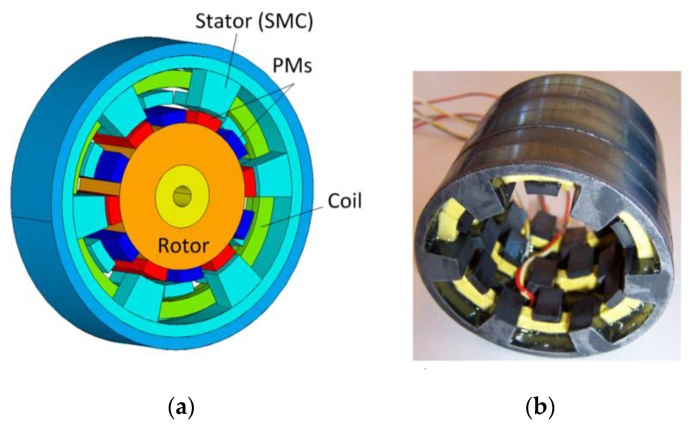
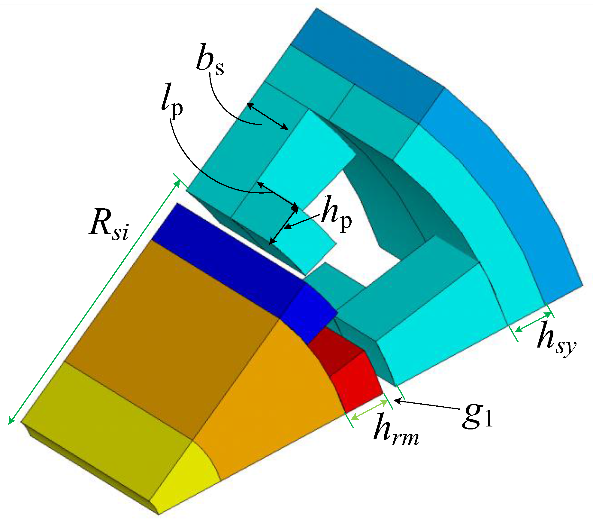
Table 1.
Manufacturing variations for some factors of PM motors.
| Description | Ideal | Variation |
|---|---|---|
| Magnet dimension | Nominal | Nominal ± ΔTolerance |
| Magnet strength | Nominal | Nominal ± 5% |
| Magnet disposition | 0 deg | 1.0 deg |
| Magnetization offset | 0 deg | 1.0 deg |
| Copper diameter | Nominal | Nominal ± ΔTolerance |
| Air gap length | Nominal | Nominal ± ΔTolerance |
| Eccentricity | 0 mm | 0.35 mm |
Table 2.
Comparison for RSM, RBF and Kriging models.
| Model | RSM | RBF | Kriging |
|---|---|---|---|
| Equation | |||
| Explanations | β: coefficient matrix | βi: coefficient matrix | β: coefficient matrix |
| X: structural matrix | H(∙): RBF function | : basis function | |
| : a random error | : Euclidean norm | a stochastic process with mean of zero, variance of σ2, and covariance related to correlation function matrix. | |
| Popular model basis functions | Linear and quadratic polynomials | Gauss, multiquadric, and inverse multiquadric | Constant, linear and quadratic polynomials |
| Correlation functions | n/a | n/a | Gauss and exponent |
| Parameter estimation | |||
| Estimation method | Least square method | n/a (no error term) | Best linear unbiased (for β), and maximum likelihood (for σ2) estimation methods |
| Modeling features | Global trend (mean response) | Global trend | Global trend and local deviation |
| Model complexity | Low | Middle | High |
Table 3.
Main dimension and design parameters of the CPM prototype.
| Par. | Description | Unit | Value |
|---|---|---|---|
| - | Number of poles | - | 12 |
| Rso | Stator outer radius | mm | 33.5 |
| Rsi | Stator inner radius | mm | 21.5 |
| Rshai | Radius of shaft hole | mm | 2.5 |
| bs | Width of side wall | mm | 6.3 |
| hrm | Radial length of magnet | mm | 3 |
| ρ | SMC core’s density | g/cm3 | 5.8 |
| g1 | Air gap | mm | 1 |
| hp | Claw pole height | mm | 3 |
| hsy | Stator yoke thickness | mm | 3 |
| lp | Axial length of claw pole | mm | 5.8 |
| Nc | Number of turns of winding turns | turn | 256 |
Table 4.
Sensitivity analysis results for the CPM.
| Par. | Local SA | Global SA | ANOVA |
|---|---|---|---|
| Rsi | 0.0267 | 0.0267 | - |
| bs | 0.1095 | 0.0990 | * |
| hrm | 0.0754 | 0.0876 | * |
| ρ | 0.1441 | 0.1587 | * |
| g1 | 0.0141 | 0.0171 | - |
| hp | 0.0053 | 0.0102 | - |
| hsy | 0.0019 | 0.0026 | - |
| lp | 0.0222 | 0.0131 | - |
* stands for significant factor for ANOVA.
Table 5.
Optimization results of the CPM.
| Par. | Unit | Initial Design | Multi-Level Optimization | Direct Optimization (FEM + DEA) |
|---|---|---|---|---|
| η | % | 78.0 | 82.4 | - |
| Pout | W | 60 | 163 | - |
| Cost | $ | 14.18 | 9.17 | - |
| FEM samples | - | - | 604 | 9000 |
Table 6.
Defects per million opportunities regarding sigma level.
| Sigma Level | DPMO (Short Term) | DPMO (Long Term) |
|---|---|---|
| 1 | 317,400 | 697,700 |
| 2 | 45,400 | 308,733 |
| 3 | 2700 | 66,803 |
| 4 | 63 | 6200 |
| 5 | 0.57 | 233 |
| 6 | 0.002 | 3.4 |
Table 7.
Main dimensions and parameters for the TFM.
| Par. | Description | Unit | Value |
|---|---|---|---|
| - | Number of stator teeth | - | 60 |
| - | Number of magnets | - | 120 |
| PM circumferential angle | deg. | 12 | |
| WPM | PM width | mm | 9 |
| Wstc | SMC tooth circumferential width | mm | 9 |
| Wsta | SMC tooth axial width | mm | 8 |
| Hstr | SMC tooth radial height | mm | 10.5 |
| Nc | Number of turns of winding | - | 125 |
| Dc | Diameter of copper wire | mm | 1.25 |
| g1 | Air gap length | mm | 1.0 |
Table 8.
Main dimensions and parameters for the TFM.
| Par. | Cost | Pout | Jc | POF |
|---|---|---|---|---|
| Unit | $ | W | A/mm2 | % |
| Deterministic | 27.8 | 718 | 6.00 | 49.63 |
| Robust | 28.8 | 700 | 5.76 | ~0 |
© 2017 by the authors. Licensee MDPI, Basel, Switzerland. This article is an open access article distributed under the terms and conditions of the Creative Commons Attribution (CC BY) license (http://creativecommons.org/licenses/by/4.0/).
Share and Cite
MDPI and ACS Style
Lei, G.; Zhu, J.; Guo, Y.; Liu, C.; Ma, B. A Review of Design Optimization Methods for Electrical Machines. Energies 2017, 10, 1962. https://doi.org/10.3390/en10121962
AMA Style
Lei G, Zhu J, Guo Y, Liu C, Ma B. A Review of Design Optimization Methods for Electrical Machines. Energies. 2017; 10(12):1962. https://doi.org/10.3390/en10121962
Chicago/Turabian StyleLei, Gang, Jianguo Zhu, Youguang Guo, Chengcheng Liu, and Bo Ma. 2017. "A Review of Design Optimization Methods for Electrical Machines" Energies 10, no. 12: 1962. https://doi.org/10.3390/en10121962
Note that from the first issue of 2016, this journal uses article numbers instead of page numbers. See further details here.