1. Introduction
With the increasingly serious energy problem, wind energy has gradually become the most rapidly developed and widely used renewable energy in the world [
1,
2]. As the direct generators of wind energy, wind power units are getting higher and higher as their capacity increases. In addition, the sea environment is wet and rainy, the grounding environment is complex, thunderstorm phenomena are frequent, so the probability of lightning strikes on offshore wind turbines (WTs) has increased considerably. According to the statistics of the International Electro Technical Commission, the damage rate of wind power units caused by lightning strikes is up to 14% in areas where thunderstorms are frequent. WTs are the most valuable components of wind farms, representing more than 60% of the total investment in wind power. Lightning strikes not only cause damage to the WTs themselves, but also cause the wind power to be shut down when serious, even threatening the safe operation of the power grid [
3,
4]. Therefore, the lightning protection of offshore WTs has become a major technical problem which needs to be urgently solved.
When a wind turbine is struck by lightning, a thunderbolt that carries a huge amount of energy will be injected into the top of the unit’s blades, or a lightning rod in the rear of the nacelle. The current flows through the metal conductor inside the blade, the guide path of the engine room, the tower body, the grounding device of the WTs, and finally the discharge flow enters the ground. In the transient process of the whole discharge, the lightning flow can cause the potential jump of all parts of the WTs, which may cause a counterattack or insulation damage to the equipment [
5]. Due to the power system and control system present in the engine room, it is very important to protect the engine room.
At present, domestic and foreign scholars have mainly reported experimental research and theoretical analysis on the field of lightning over-voltage and electromagnetic effects. In an experimental study, the Japanese scientist Yamamoto built a scale model of a wind turbine, used the electrode simulated lightning generator to complete the lightning simulation test, and analyzed the potential rise of the bottom of the cylinder [
6]. However, due to the huge cost of experimental research [
7], the experimental model is not flexible. With its dual characteristic of voltage source and current source, lightning is difficult to simulate, so to date most research on the characteristics of lightning are based on computer theoretical analysis. At present, most research on lightning transient response is carried out for lightning protection of the steel structure model of buildings. Zhang at Beijing Jiao Tong University studied the distribution characteristics of lightning current in the lightning protection system when lightning strikes buildings [
8]. The electromagnetic transient software EMTP (ATP, Bonneville Power Administration, Portland, OR, USA) is widely used in the lightning transient calculation of wind farms, and it is a powerful tool for designers and researchers [
9]. Zhao and Wang, from the Chinese Academy of Sciences, have established a simplified “tower-transmission line” model for EMTP for the lightning transient potential problem [
10]. The transient over-voltages of the tower and transmission lines have been calculated and analyzed. In the aspect of theoretical analysis, Harrington proposed the method of moment analysis of lightning electromagnetic induction [
11]. Zhang discussed the influencing factors of the potential rise of the WTs grounding device by the moments method [
12,
13]. References [
14,
15,
16] use the finite-difference time-domain (FDTD) method to analyze the WTs ring grounding pole. In [
17,
18,
19], the lightning protection model of a power system is proposed. These works provide the reference for the establishment of offshore wind turbine lightning models.
In [
20], the influence of the tower and transmission line interdispersion capacitance is considered, and the induced overvoltage of the tower internal transmission line is analyzed. Although the lightning transient response to the WTs has been studied more, it is mainly based on onshore WTs. The influence of oceanic factors, especially the seawater layer, on the transient potential of the WTs, is not considered. Studies on the transient potential of the nacelle are limited. In addition, the traditional empirical formulae [
21,
22] cannot show the influence of blade rotation angle on the impedance model. The existing research lacks an analysis of the wave impedance characteristics of the unit, which affects the accurate calculation of the potential of each part and each point of the generator when the lightning current occurs in the unit.
In this paper, a grounding model of offshore WTs is established firstly, and the numerical calculation method of the impact grounding resistance of the WTs is proposed. The wave impedance model of the blade and the tower is established according to the rotation characteristics and the conical antenna theory. Based on the wave impedance model, an alternative transients program electro-magnetic transient program (ATP-EMTP) simulation model of the lighting WTs is built and compared with the traditional impedance model. The influence of different factors on the transient overvoltage is analyzed. This has certain guiding significance for the design of offshore wind turbine lightning protection systems.
2. Modeling of Offshore WT Lightning Transient Effect
When the offshore WT is struck by lightning, the lightning current will flow through the lightning channel wave impedance, and will form a certain circulation path on the WT at the same time. The lightning current goes through the blade, tower, grounding device, and finally into the ground. In order to accurately analyze the transient overvoltage of the WT, an accurate calculation model of each part should be established.
2.1. Numerical Calculation of Offshoree Wind Turbines Grounding Resistance
The design of the offshore wind turbine grounding system is different from that of traditional onshore WTs. The pipe rack structure is used as the foundation of offshore WTs. Considering the economy and the ease of construction, the general engineering uses the foundation as the natural grounding body. At present, the basic forms of offshore wind turbine can be subdivided into single pile foundations, gravity foundations, suction foundations, multi-pile foundations and floating foundations [
23]. Among them, the most widely used is the single pile foundation, and its structural diagram is shown in
Figure 1.
The grounding resistance is calculated by point current source Green function in the soil. The Laplace equation of cylindrical coordinate system is solved by Fourier transform and separation of variables [
24]. The potential function of the midpoint current source is obtained, as shown in Equation (1):
In Equation (1),
φ(
λ) and
γ(
λ) are undetermined coefficients, and
J0(
λr) is the first class of zeroth order Bessel functions,
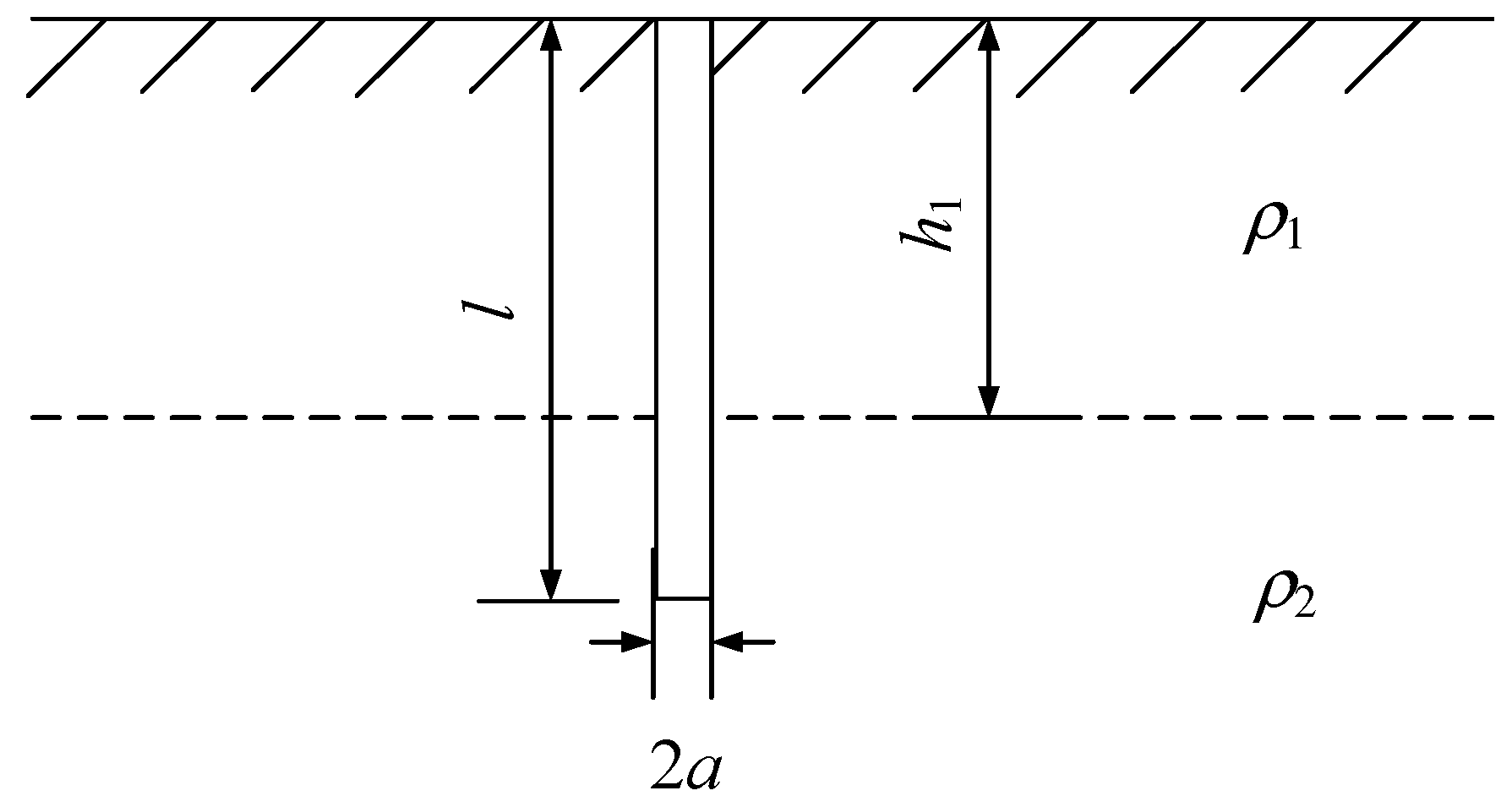
λ is an arbitrary constant. The ground environment of offshore wind turbine is divided into sea water layer and soil layer. The grounding body is divided into the upper and lower two sections, and the potential function should be calculated respectively [
25]. The mathematical model is shown in
Figure 2.
Where
l is the total length of grounding,
a is based radius,
h1 is the upper water depth,
ρ1 is the upper seawater resistivity,
ρ2 is the lower resistivity of seabed sand. The current density of the ground body in the upper seawater and the lower soil is
δ1 and
δ2 respectively, and the relation is as shown in Equation (2):
The potential functions of the upper seawater and the underlying soil
ϕδ1 and
ϕδ2 can be calculated by using Equations (1) and (2), respectively. Based on the superposition principle, the numerical expression of the impulse grounding resistance of the single pile wind turbine in the double deck grounding environment of the ocean can be obtained, as shown in Equation (3):
In Equation (3),
α is the impulse factor. Considering that the single pile foundation is a vertical tube, its radius is much larger than the radius of flat steel in the common grounding device. The spark discharge around the grounding body is not obvious [
26]. The approximate value of
α is 1.
2.2. Modeling of Propeller Blade Wave Impedance Considering Rotation Factor
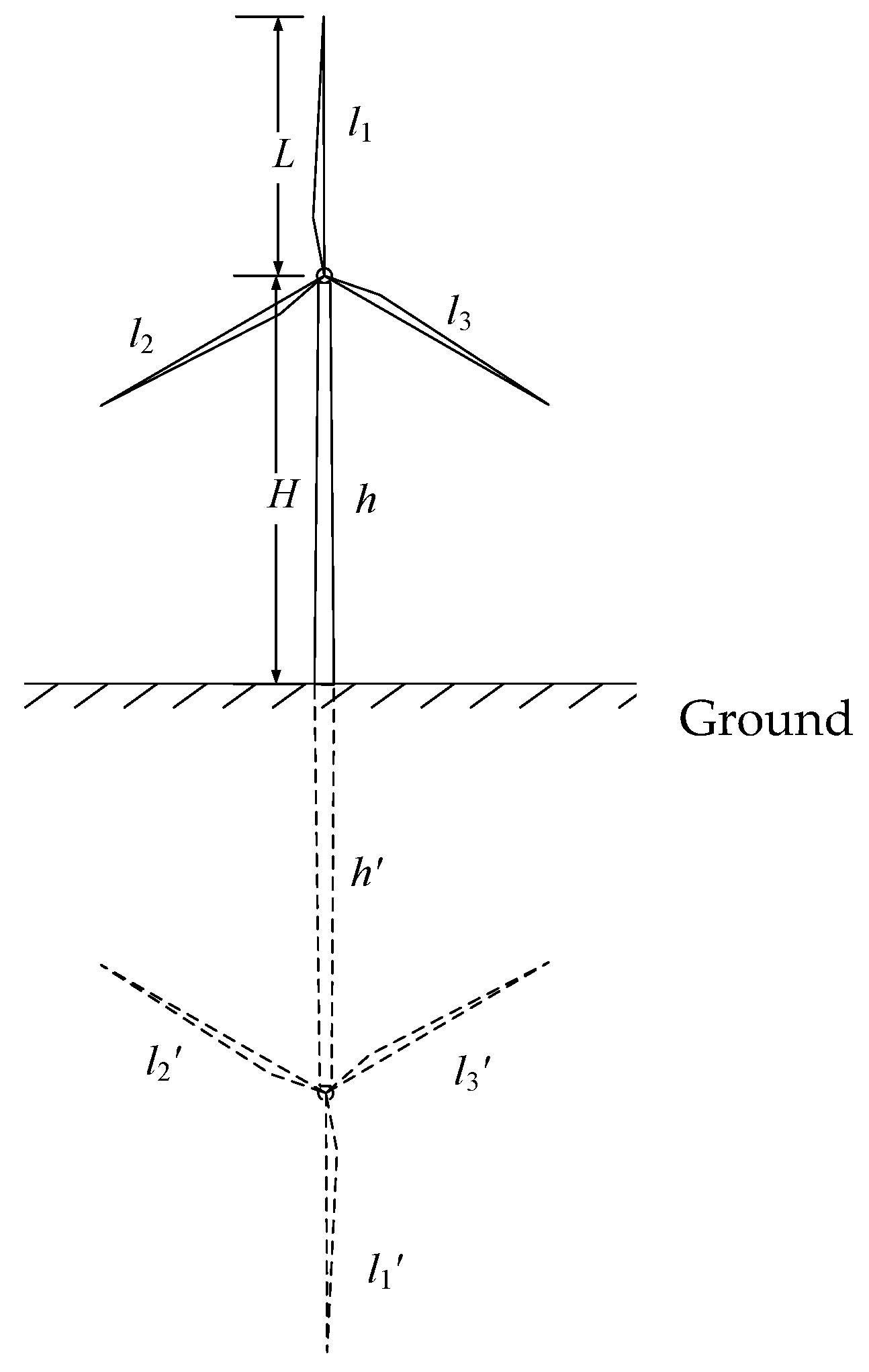
The rotation of the blade will change the capacitance, inductance and other parameters of the blade. From the definition of wave impedance, it can be seen that the blade wave impedance changes with the increase of blade length. Therefore, in order to accurately establish the blade wave impedance model, the simultaneous effects of rotation angle, height of tower and blade length should be taken into account. Because of the good conductivity of sea water, the sea surface can be considered as a good conductor. Calculation of wind turbine and its mirror is shown in
Figure 3, where
l1,
l2,
l3,
h respectively represent three blades and tower,
l1′,
l2′,
l3′,
h′ respectively represent the mirror images of the wind turbine blades and the tower.
The blade capacitance is calculated by the mean potential method. Considering that the height of the offshore wind turbine is much larger than the radius of the tower, the radius of the tower can be neglected. It is assumed that the blade and tower are uniformly charged and the charge is concentrated on the axis, and the charge linear density is
τ. As shown in
Figure 3, the blade to ground capacitance
Cg, the blade to column capacitor
Clh and the blade capacitance
Cl1/2 can be obtained:
In Equations (4)–(6),
L is the blade length,
ε is the space conductivity, and
D is the distance between the two micro units. The inductance of a conductor consists of two parts, the inner inductance and the outer inductance, but considering that lightning current changes rapidly and the lightning transient process time is short, it is generally recognized that the internal inductance is negligible in the calculation of lightning electric parameters, and only the external inductance should be considered [
27]. For space conductors, the inductance is the sum of inductance and mutual inductance. At present, Neumann integral method in electromagnetic field theory is widely used to calculate self-inductance and mutual inductance in domestic and foreign scholars [
28]. According to the geometrical relationship of the blade, the self-inductance
Lg, the mutual inductance
Llh and the mutual inductance between blades
Ll1/2 can be obtained:
In Equations (7)–(9), θ1, θ2, θ3 respectively is the angle between the blade and blade, blade and mirror tower, the blade and blade. μ is the spatial permeability.
From the above analysis, the total capacitance and total inductance of a single blade can be obtained. According to the definition of wave impedance, the wave impedance of the blade can be obtained, as shown in Equation (10):
In this paper, the blade wave impedance model is compared with the conventional fan blade wave impedance model. Not only the blade length and the height of the drum are taken into account, but also the rotation angle of the blade is taken into account.
2.3. Modeling of Offshore Wind Turbines Tower Impedance
When the lightning current passes through the wind turbine tower, the wind turbine tower is made into a vertical tower, ignoring the difference between the radius of the upper and the lower parts. The process of lightning passing through the tower of a wind turbine can be regarded as the propagation in the form of spherical wave [
29]. This is similar to the wave process of conical antenna. The wave impedance can be obtained by using the cone antenna theory [
30,
31,
32].
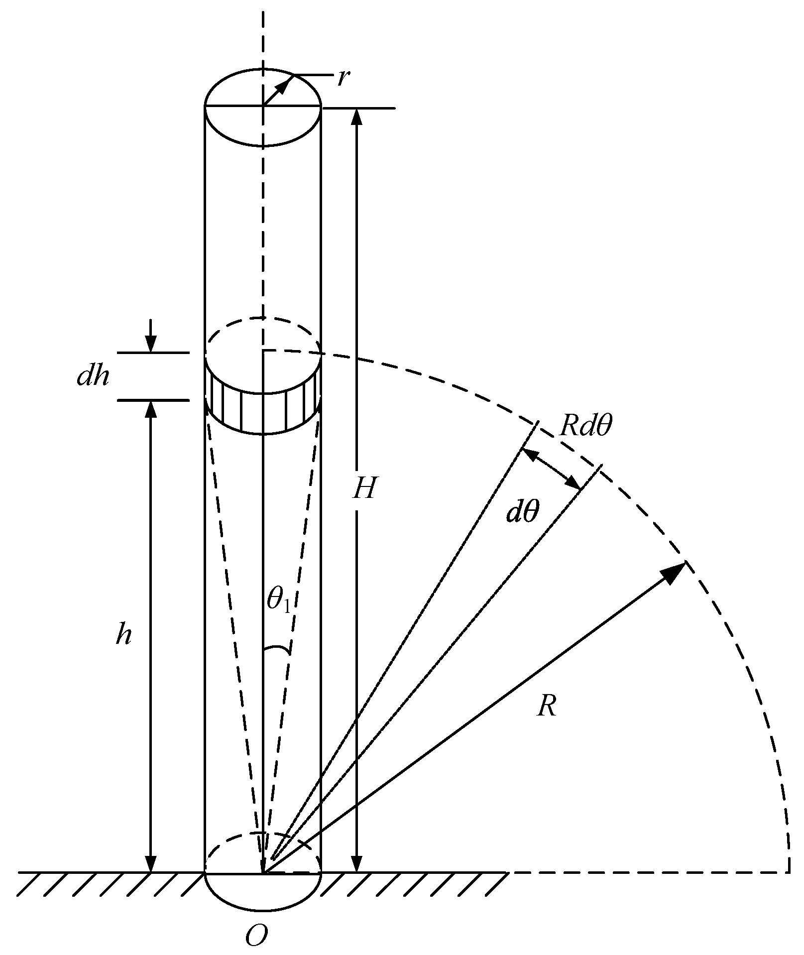
Figure 4 is a conical antenna equivalent model of an offshore wind turbine tower. The height of the tower is
H, and the radius of the upper and lower bottom is
r. A differential element
dh on wind turbine tower is selected, the height from the ground is
h, the inverted cone vertex
O is the projection point of the center of the tower on the ground, and
θ1 is half of the cone vertex angle. The arbitrary micro angle
dθ is selected,
R is the distance between the
O and the outer boundary of the infinitesimal segment, then the arc length of the micro arc is
Rdθ. According to the geometric relation of the graph,
r =
R × sin
θ1,
can be obtained.
The wave impedance of the differential element
dh Z′ can be obtained from the cone antenna theory, as shown in Equation (11):
The equivalent wave impedance of the whole offshore wind turbine tower
Z can be derived by finding the integral and averaging along the tower body, as shown in Equation (12):
2.4. Offshore Wind Turbine Integrated Electromagnetic Transient Model
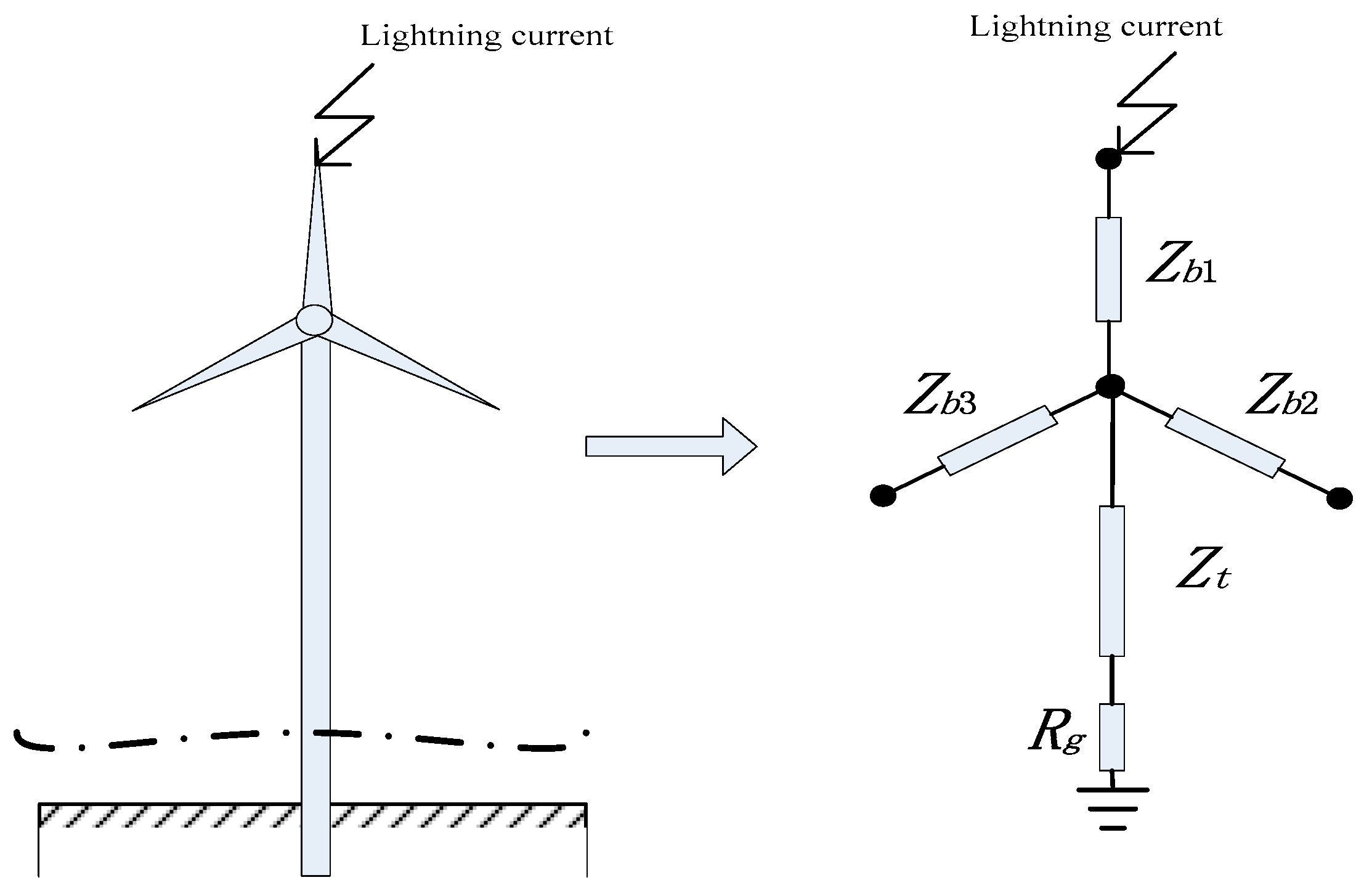
According to the wind turbine blade, the tower body wave impedance and the offshore wind turbine impact grounding resistance model, the integrated model of the offshore wind turbine lightning transient integration can be obtained, as shown in
Figure 5.
In
Figure 5,
Zb1,
Zb2,
Zb3 respectively represent the impedance of the three blades of the wind turbine.
Zt represents the wave impedance of the wind turbine tower,
Rg denotes the equivalent impact resistance of the offshore wind turbine.
3. Lightning Parameters Influence Offshore WT Lightning Transient Characteristics
In this paper, the lightning current channel is simplified according to [
28], ignoring the influence of the pilot and the distortion of the lightning current waveform in the discharge channel. Assuming the discharge channel is perpendicular to the ground and the current is concentrated on the axis of the channel, the lightning transport process utilizes the Petersen current source equivalent circuit instead.
3.1. Lightning Parameter Model
Lightning is a discharge phenomenon in the atmosphere that occurs randomly between clouds and clouds or between clouds and the ground. Lightning in nature has a polarity. In order to express the convenience, it is set as positive polarity in the research. Since the double exponential model of lightning flow can be conveniently differentiated and integrated, a double exponential model is adopted to simulate lightning current. Its mathematical expression is shown in Equation (13):
where
I0 is the peak of the lightning current,
η is the peak correction factor of the lightning current. In the following calculations,
I0 = 120 kA,
η = 0.92;
α(s) and
β(s) are the time constants determined by the wave head time and the wave duration.
Based on lightning observation and previous research [
13,
33], this paper uses 8/20 μs, 120 kA standard lightning current waveform to simulate the lightning current suffered by a wind turbine. The parameters
α and
β were 7.713 × 10
4 s and 2.484 × 10
5 s.
In addition to the parameters mentioned above, this paper also considers the lightning channel wave impedance
ZM. The integrated model of the offshore wind turbine lightning transient integration considering lightning channel wave impedance can be obtained, as shown in
Figure 6.
In many papers, for example, [
34],
ZM ≈ 300 Ω, but, through the observation and analysis of former Soviet Union scientists [
35], the value of the wave impedance of the lightning channel is not constant, and its value is related to the magnitude of the lightning current. The impedance of the lightning channel varied from 300 to 3000 Ω. When the lightning current amplitude is 30–200 kA, the value of the wave impedance of the lightning channel is relatively stable, about 300–600 Ω. According to the data in [
36], the relation between the lightning current amplitude and the wave impedance of the lightning channel is obtained, as shown in
Figure 7.
When the other parameters remain unchanged, the lightning channel impedance is 300 Ω, as shown in
Figure 8, the transient response of the WT lightning impulse is significantly different from when the
ZM is not considered in the model (ignore
ZM),as shown in
Figure 5. The model considers
ZM, which is very different from not considering
ZM. Therefore, it is of some value to study the influence of the actual value of lightning channel wave impedance on the transient response.
3.2. Lightning Channel Wave Impedance
This paper uses 8/20 μs standard lightning current waveform to simulate the lightning current suffered by wind turbine. The lightning current amplitude range 5–100 kA is used to study the lightning transient response of different lightning channel impedance parameters (the actual value of
ZM can be obtained from
Figure 7), the results shown in
Figure 9.
It can be seen from
Figure 9 that when the lightning current is relatively small, the result will greatly deviate when
ZM ≈ 300 Ω is used in the calculations. With the increase of lightning current, the relative error decreases gradually. In this paper, the value of lightning channel wave impedance corresponds to the amplitude of the lightning current, which is more in line with the actual situation.
In the calculation of lightning protection, lightning wave impedance values generally choose 300 Ω, however, through the analysis of this section, it can be found that if the lightning channel impedance value is simulated in the normal lightning protection standard (300 Ω), the result is that the transient voltage peak in the nacelle is smaller than the actual peak. If the lightning protection is implemented according to ZM ≈ 300 Ω, this will greatly increase the probability of lightning damage the wind turbine. The nacelle can be penetrated, which will bring serious consequences, endangering the safe operation of the fan and cause significant economic losses.
Therefore, the analysis results of this section will have certain guiding significance for the lightning protection calculation of offshore WTs. At the same time, the lightning model must be improved.
4. Factors Influencing Offshore WT Lightning Transient Characteristics
The single pile offshore wind turbine is used as the standard model in the simulation (parameters shown in
Table 1), and the transient potential of the offshore wind turbine nacelle is analyzed. The internal equipment circuit adopts separate grounding system, the transient potential of the internal equipment is much less than the transient potential of the nacelle, and the potential difference between the equipment and the nacelle can be approximately equal to the nacelle potential [
5]. Therefore, the transient potential analysis in the nacelle is the main factor.
After simulation calculation, the rotation angle has less influence on the lightning transient response of the offshore wind turbine, and the influence of rotation angle can be neglected in the simulation process. Therefore, this section is not taking into account the impact of the rotation angle.
4.1. Seawater Depth Influence on Transient Response of WT Lightning Impulse
For an offshore WT, the depth of the sea layer is an important factor affecting the grounding parameters. According to Equation (3), with the decrease of the sea water layer, the impulse grounding resistance of the offshore wind turbine will increase. When the sea water layer is 0 m, it can be approximately regarded as a land WT. According to the different soil layer resistivity, the grounding resistance changes in the range of 0–20 Ω [
37]. At different ocean depths, the transient potential of the wind turbine nacelle is obtained from the integrated model, as shown in
Figure 10.
It can be seen from
Figure 10 that the transient overvoltage of the lightning impact of the offshore WT and the onshore WT is different, the transient voltage of the land WT is obviously larger than that of the offshore WT, so it is very necessary to model and analyze the offshore WT separately.
It can be seen that the maximum value of transient potential in the nacelle is related to the depth of the seawater layer, and the maximum value appears in the first oscillation period.
The complex environment of offshore WTs makes them very different from onshore WTs. The greater the depth of the sea, the smaller the impulse grounding resistance, the peak value of the transient voltage of the nacelle decrease. Under the premise of ensuring the normal operation of the equipment, the deeper the sea water, the more conducive to lightning protection design. This has guiding significance for the site selection of offshore WT. In full consideration of other conditions, the WT should be selected in deep seawater.
4.2. Influence of Blade Length and Tower Height on WT Lightning Impulse Transient Response
The other parameters are kept unchanged, and the length of the blades (
L = 40 m,
L = 70 m and
L = 100 m) and the height of the tower (
H = 90 m,
H = 120 m and
H = 150 m) are simulated. The influence of the blade length and the tower height on the transient potential of the nacelle (
Figure 11) and the oscillation frequency (as shown in
Table 2) are analyzed. The transient voltage peak of the nacelle can be approximated in Equation (14):
where
Up is the voltage peak in the nacelle,
Uh and
Ug are the voltage drops on the tower and the ground.
It can be seen that as the tower height increases, the transient potential of the WT nacelle shows an upward trend. With the increase of blade length, the transient potential of the WT nacelle is decreasing. When the WT is struck by lightning, a high tower and short blades will increase the probability of damage to the nacelle.
The simulation results have guiding significance for selecting the height of the tower and the length of the blade when constructing an offshore WT. Short towers and long blades are good for WT lightning protection.
4.3. Lightning Parameters Influence on WT Lightning Impulse Transient Response
The time of the wave front and the time of the wave tail are the two main parameters of the lightning current waveform.
Figure 12 is a schematic diagram of three kinds of lightning current, 4/20 μs, 8/20 μs and 8/50 μs. Using the three different wave fronts and wave times, the lightning current waveform is simulated to get the transient potential at the nacelle, as shown in
Table 3.
The overall impedance of the wind turbine is perceptive, so the voltage value in the nacelle is available in Equation (14) [
12]:
where
L is the wind turbine equivalent inductance,
R is the wind turbine equivalent resistance,
i is the lightning current.
di/
dt is the sum of the changes of the lightning flow itself and the variation of the current reflection.
It can be seen that the wave front time has a great influence on the transient process of the lightning stroke offshore wind turbine. Since the wave front time is much smaller than the wave wake time, when the wave front time decreases, the high frequency component obviously increases, and the di/dt value becomes larger, then the transient potential peak value is higher obviously. The lightning current wave steepness in front of the wave is very big. U is mainly decided by the first item in Equation (14). The gradient of the double exponential current wave in front of the wave is the higher, the overvoltage maximum usually occurs in the first period.
Lightning currents tail gently, the wave tail time change has little effect on the di/dt, then the impact on the nacelle transient potential is also smaller.
There is no fixed waveform in the nature of lightning, but through this section analysis, it can be concluded that when other parameters are the same, the smaller the time of the wave front, the greater the possibility of damage to the WT. In the design of lightning protection, priority should be given to the lightning wave with less front time.
4.4. Lightning Point Influence on WT Lightning Impulse Transient Response
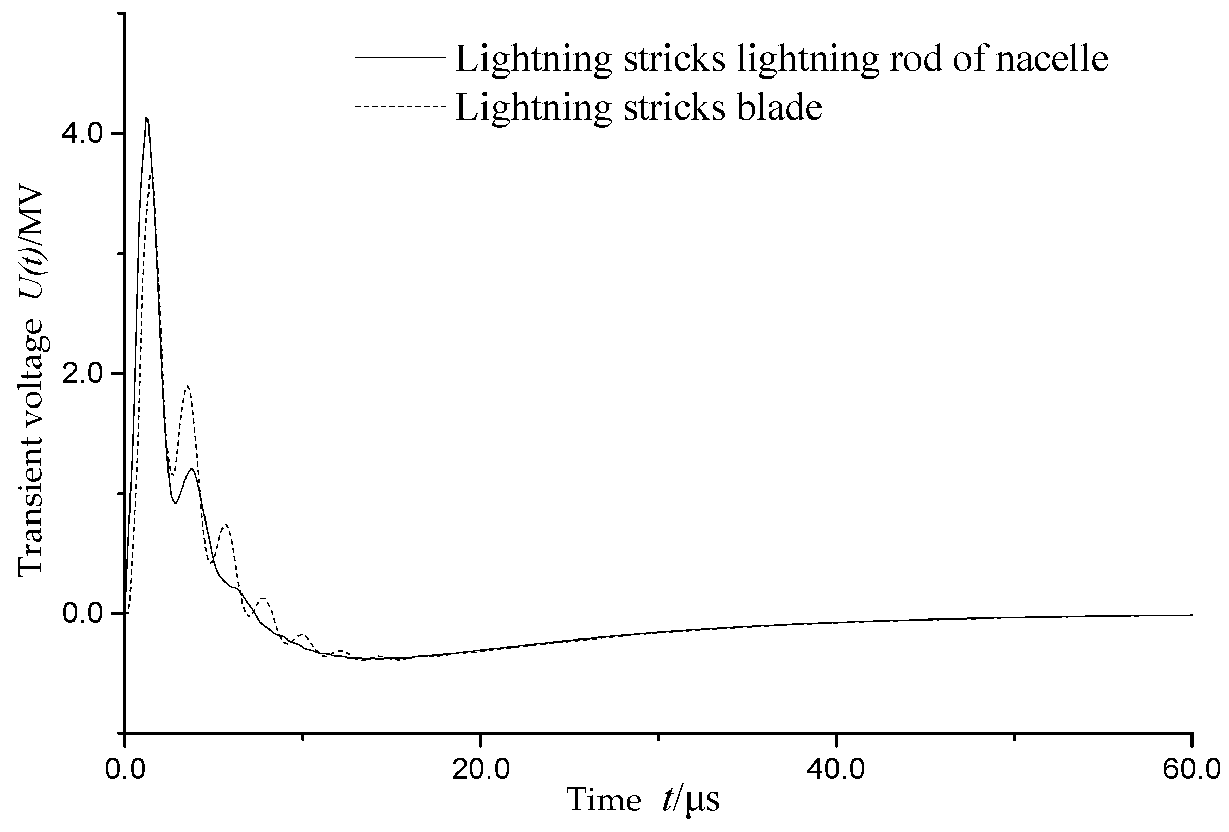
The offshore WT is struck by lightning, and the lightning current may be injected from the tip of the wind turbine blade tip or the rear of the engine room. Therefore, the different lightning point positions will lead to the change of lightning current on the wind turbine, and then have an impact on the transient process of lightning stroke. In this paper, the transient potential response of the wind turbine nacelle is studied by analyzing the two different lightning strike points.
As shown in
Figure 13, due to the change of the current path, when lightning strikes the lightning rod of nacelle, the transient potential peak is about 11.6% higher than when lightning strikes blades. Therefore, emphasis should be placed on the nacelle lightning protection. The nacelle is the focus of lightning protection, in order to prevent lightning damage to all kinds of equipment in the cabin, causing major accidents.
5. Conclusions
After lightning current strikes the tower of a wind turbine, the tower body becomes in an instant a high voltage equipotential body. The instantaneous voltage rise can reach several hundred kilovolts or even a few MV, the tower body moment potential uplift is likely to cause insulation breakdown, damage fire automatic control system and communications equipment, electrical equipment, but also the power line and the signal line of the tower body voltage can induce a dangerous anti-strike. Therefore, in the lightning protection design of wind turbine, it is necessary to fully analyze the fan and lightning parameters, try to reduce the harm of lightning to the unit, and ensure the safe and reliable operation of the unit. The research of this paper has guiding significance for this problem, the main features of this paper are as follows:
- (1)
According to the characteristics of the offshore WT environment and lightning parameter, the integrated multi-wave impedance model of the offshore wind turbine is established.
- (2)
Considering that the lightning channel impedance can effectively reduce the transient voltage and oscillation frequency, the actual peak value of transient overvoltage is higher than when ZM is 300 Ω. This requires the improvement of lightning protection levels.
- (3)
There are significant transient overvoltage differences between offshore and onshore WTs. The peak value of transient overvoltage in the nacelle increases with the decrease of seawater depth when the WT is struck by lightning. This has a certain guiding significance for the location of offshore WT and selection of equipment.
- (4)
When building an offshore WT, the tower height should be relatively small, and the blade length should be relatively large. The smaller the wave front time, the greater the harm caused by lightning current. In the design of lightning protection, emphasis should be placed on the lightning protection of the nacelle. The blade rotation angle has less influence on the transient voltage peak of the nacelle and can be neglected.


