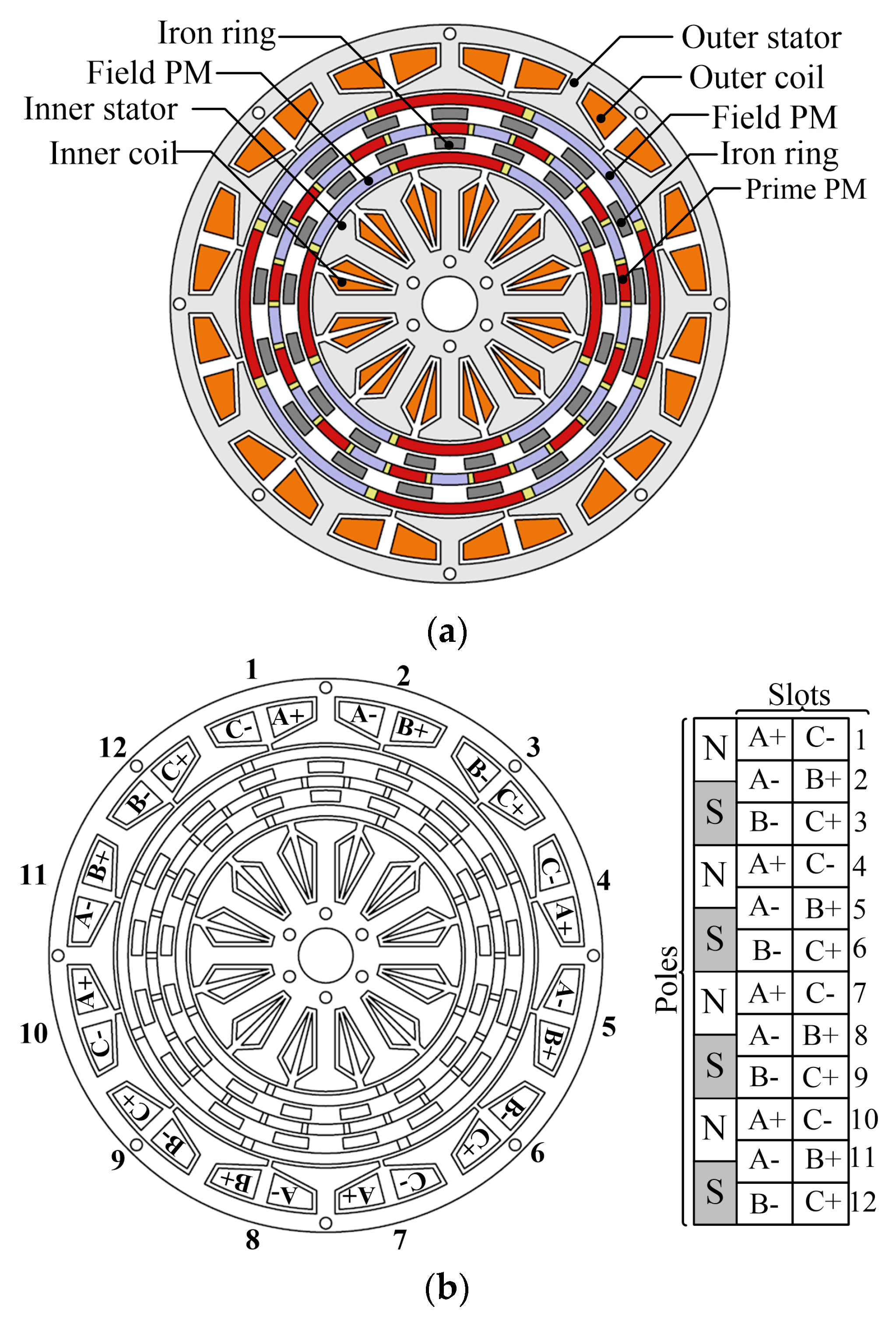
Article

Power Characteristics Analysis of a Novel Double-Stator Magnetic Geared Permanent Magnet Generator

by
Shehu Salihu Mustafa
1,*,
Norhisam Misron
1,2,*,
Mohammad Lutfi Othman
1 and
Hanamoto Tsuyoshi
3
1
Department of Electrical & Electronic, Faculty of Engineering, Universiti Putra Malaysia, 43400 UPM Serdang, Selangor, Malaysia
2
Institute of Advanced Technology, Faculty of Engineering, Universiti Putra Malaysia, 43400 UPM Serdang, Selangor, Malaysia
3
Department of Biological Functions Engineering, Graduate School of Life Science and Systems Engineering, Kyushu Institute of Technology, 2-4 Hibikino Wakamatsu-ku, Kitakyushu 808-0916, Japan
*
Authors to whom correspondence should be addressed.
Energies 2017, 10(12), 2048; https://doi.org/10.3390/en10122048
Submission received: 12 June 2017 / Revised: 23 September 2017 / Accepted: 5 October 2017 / Published: 4 December 2017

Abstract

:
This paper presents the design, fabrication and experimental power analysis of a novel double-stator magnetic geared permanent magnet (DSMGPM) machine which comprises of a double-stator permanent-magnet (PM) machine integrated a with triple rotor magnetic gear. The proposed machine can upscale the low-speed rotating magnetic field of the prime PMs on the prime rotor by using the modulation effect produced from the pole-pieces to high-speed rotating magnetic field from the field PMs. The low-speed prime rotor can also increase the speed of the field PM rotor and excite the coil windings to induce an electromotive force (EMF) resulting in electrical power. Thus, the machine is proposed for power generation in low-speed renewable energy applications such as wind turbines and tidal power generators. The proposed machine topology is presented and discussed while the performance power characteristics are evaluated experimentally. A prototype is fabricated and the measured results are in good agreement with the calculated results, therefore validating the proposed magnetic geared machine design.

1. Introduction

Research in magnetic gearing has increased in the last 10 years because of its potential for efficient transmission torque, lubrication free maintenance, overload protection and non-contact operation compared to problems of mechanical gears [1]. Studies [2,3,4,5,6,7] have shown that magnetic gears can reach a torque density of 100 kNm/m3 and by integrating a magnetic gear with a PM machine; the resultant magnetic geared machine can be applied in low-speed high torque applications such as traction motors and as generators in low-speed renewable energy power generation [8,9]. Reference [10] reported that a double-stator PM machine achieved a higher torque density much greater than a single-stator PM machine.
The research on magnetic geared double-stator PM machines has gradually increased recently in the last 10 years, although very few studies have been published on this class of MG machines. A double-stator MG PM machine was proposed in [11] with a simpler structure comprised of two PM rotors and a single rotating modulating iron ring rotor. The magnetic geared machine was designed to operate in a motor/generator power-splitting mode for applications in electric vehicles (EVs). In [12] single-ring and dual-ring types of double-stator MG PM machine design were proposed. Each MG PM machine consisted of a single PM rotor for low-speed, high torque applications. An improved modified design was presented in [13] with two PM rotors and the removal of the modulating pole piece rotor. The pole pieces were inserted between each PM to achieve a power-split electromechanical device (motor/generator). Two double-stator magnetic flux-modulated mnemonic machine designs that combined magnetic gearing principle and the concept of flux-mnemonic were reported in [14]. The first machine design presented was a dual-layer PM magnetic flux-modulated mnemonic machine (MFMM) with PMs fixed on both the outer stator and rotor, while the second machine design proposed was a single layer PM magnetic flux-modulated mnemonic machine with all PMs fixed only on the outer stator.
Even though previous reported studies conducted on double-stator MG PM machines have contributed greatly to the present knowledge about magnetic geared machines, it can be reasonably assumed that the absence of published experimental data in [11,12,13,14] suggests that the performance characteristics of magnetic geared double-stator PM machines have not been fully well studied to identify areas requiring further investigation.
The purpose of this paper is to address this gap in previous studies with experimental data, by reporting the power characteristics of a novel structure of a double-stator magnetic geared PM machine from a demonstrator prototype. The machine structure consists of three PM rotors and two stationary iron ring pole pieces, which is realized from a triple-rotor magnetic gear integrated with a double-stator PM machine. The aim is to determine the electrical power characteristics and efficiency when the low-speed prime rotor magnetic field is up scaled to the high-speed magnetic field on both the outer and inner field PM rotors using the magnetic gear ratio and modulation effect of the ferromagnetic pole pieces. A magnetically coupled topology is used to match the magnetic gear with the double-stator PM machine. In Section 2, the machine structure and design parameters will be introduced. Section 3 will present the operating principle of the magnetic geared machine. Section 4 discusses the results and presents details of the experimental evaluation. Finally, the conclusions are presented in Section 5.

2. Machine Structure

Figure 1a shows the structure of the proposed double-stator magnetic geared machine which is designed with a bone-rotor structure design for holding one set of four pole-pair field PMs for the outer, inner and middle rotors. The proposed machine has the same number of eight field PMs on both high-speed rotors, which rotates according to the gear ratio to excite the coil windings in both outer and inner stators resulting to an induced EMF thus generating electrical power. Also the proposed MG machine uses three rotors and two modulating pole pieces to modulate the magnetic field between the outer and inner PMs to achieve the magnetic gear effect and magnetic field excitation of the stator coils. A magnetically coupled configuration is the key factor that enables the machine to operate as a magnetic gear and electrical power generator simultaneously. The MG machine utilizes the middle prime PMs as the prime mover and the magnetic flux is modulated by dual iron pole pieces placed between the field PMs and prime PMs. Also a magnetically coupled configuration results to a series magnetic circuit that can improve its power density compared to a parallel magnetic circuit from a magnetically decoupled configuration. For the rotor structure, the rotor can be designed as a bone-rotor shape with the same thickness as the PMs. This reduces the amount of magnets to a single layer compared to the double layer adopted in cup-shaped rotors which can minimize cost and lessen the magnetic circuit. As illustrated in Figure 1a, the prime PM rotor which is the prime mover for the magnetic gear is coupled simultaneously to both inner and outer field PM rotors. The high-speed field PM rotors and stators are interconnected through magnetic field excitation and this combination is equivalent to a conventional PM electrical machine. The output torque which is applied on the high-speed field PM rotor by the magnetic gear is reacted by the torque applied on the low-speed prime PM rotor. A double-layer concentrated winding scheme is implemented for both inner and outer stators as shown in Figure 1b. The design specifications of the proposed MG machine are listed in Table 1 while the material properties of the components and coil winding specifications are given in Table 2 and Table 3, respectively.

2.1. Mechanical Structure

The double-stator PM machine and the triple rotor magnetic gear are integrated into a single compact MG machine. Figure 2 shows the mechanical structure diagram of the MG machine. The PMs on the outer, inner and prime rotors are sandwiched between three bone rotors with thickness equal to the PMs. A bone rotor structure is used to reduce the quantity of magnets to three layers and also achieve a magnetically coupled configuration between the magnetic gear and generator. To address problems of centrifugal forces on the PMs when the field PM rotors rotate at high speeds (greater than 1000 rpm), an aluminum end plate is employed to secure both ends of the three rotors. The prime PM rotor is connected to the input shaft while the outer and inner field PM rotors are independent and rotate freely on the same axis as illustrated in Figure 2. Since these two field PM rotors rotate at the same speed in similar direction, the prime PM rotor can couple or decouple the field speed and field torque simultaneously. The MG machine is composed of two stators and two modulating pole pieces as shown in Figure 2. The modulating pole pieces are machined from 3 mm thick solid steel to simplify the fabrication process. Although laminated steel would have been suitable to reduce core loss and eddy current loss but this will increase cost and difficulties in the mechanical assembly of the pole pieces. The two modulating pole pieces are aligned in the same direction to achieve modulation of the magnetic field in the air gap between the prime PMs and field PMs. A 2D finite element analysis showed that misalignment of the two modulating pole pieces will result to magnetic leakage flux in the air gaps and decrease transmission torque. Both modulating pole pieces are supported with Aluminum end rings to prevent magnetic flux leakage in the axial direction and short circuit of the pole pieces. This is to reduce loss of transmission torque and improve efficiency which is consistent with the findings reported in a study [15].
A total of seven single-row ball bearings are used for the three PM rotors to provide balanced axial rotation and also minimize strong magnetic forces from the PMs. A steel support structure is used to mount the ball bearings on both sides of the MG machine. The inner stator is mounted on the steel support structure on both sides and secured with steel bolts but this construction technique results to losses due to eddy current loops created between the steel bolts and steel support structure. The outer stator is supported by two outer casings manufactured from aluminum to reduce magnetic flux leakage and also reduce weight. The magnetic gear structure comprises of the prime PM, modulating pole piece and field PM while the generator structure comprises of the stators and field PMs. When the prime PM rotor rotates, it generates a magnetic field of pole-pair equal to the field PM by the modulating pole pieces resulting to a reaction torque on both outer and inner field PM rotors. The field PM rotors rotate synchronously based on the MG gear ratio to induce an EMF by exciting the coil windings in the stators and generate electrical power.

2.2. Machine Operating Principle

For the MG machine design Pprime = 13 and Ppfield = 4 are selected as the number of pole-pairs of the prime PM rotor and field PM rotor respectively. This pole-pair combination was selected because it yields a cogging torque factor, Cf = 1 as defined by [16] and Cf is expressed as:
C f   = 2 P field N iron L C M ( 2 P field N iron )
where Niron is the number of iron pole pieces and LCM is the least common multiple between number of field PMs and number of iron pole pieces and its transmission torque is based on the modulation of the magnetic flux between 13 pole pair prime PMs on the low-speed rotor and four pole pair field PMs on the high-speed rotor by 17 pole pieces. According to the magnetic gearing principle, the airgap flux density space harmonics and the corresponding angular speed ratio of number of pole-pairs are governed by the magnetic gear speed relationship [17]:
ω prime   = p prime | p prime p iron | ω inner +   p iron | p iron p prime | ω iron
p inner = p outer   = | p iron   p prime |  
where ωinner, ωprime, and ωiron are the angular speeds of the inner PM rotor, the prime PM rotor and the iron pole pieces respectively while pprime, pinner, pouter and piron are the pole pairs of prime PMs, inner PMs, outer PMs and pole numbers of iron pole pieces respectively. The magnetic gear ratio Gr can be expressed as:
  G r   = ω prime ω inner | ω iron = 0 = p prime p inner
It can be seen that a magnetic gear ratio of 3.25 is calculated for the magnetic geared machine and the minus sign indicates that both outer and inner PM rotors rotate simultaneously in the same direction opposite to the prime PM rotor. Since the calculated number of slots per pole per phase q = 1/2 is a fractional number, a 3-phase concentrated winding topology as shown in Figure 1b is adopted for both outer and inner stators as this winding design can reduce the end windings and copper losses [18]. Although it may not produce a sinusoidal back-EMF as it has a winding factor Kw = 0.866 which is less than unity. The stator windings can be connected in star or delta configuration but this depends on the preferred EMF and operating speed. In this machine design a star wye connection is adopted by connecting the outer and inner three phases winding in series connection.

2.3. Transmission Torque

The MG machine can be viewed as a five-port machine with three mechanical ports and two electrical ports. To achieve a multi-port power flow system the two modulating iron ring pole pieces are assumed as additional rotating parts and by considering no power losses the mechanical power relationship is governed by:
T 1 ω 1 + T 2 ω 2 + T 3 ω 3 + T 4 ω 4 + T 5 ω 5 + T 6 ω 6 + T 7 ω 7 = 0
where T1, T2, T3, T4, T5, T6 and T7 are the electromagnetic torques produced on the inner stator, inner field PM, inner modulating ring, prime PM, outer modulating ring, outer field PM and outer stator respectively. The net mechanical power for the three rotors and torque ratio is obtained by:
T 2 ω 2 + T 4 ω 4 + T 6 ω 6 = 0
T r =   T 4 T 2 + T 6

2.4. DC Electrical Power in a Purely Resistive Load

Magnetic geared machines can be designed as a power splitting device, with the input as electrical power and the output as mechanical power for magnetic geared motors [19] or the input as mechanical power and the output as electrical power for magnetic geared generators [20]. The power PDC absorbed by a purely DC resistive load is the product of the DC voltage across the load and the DC current flowing through the load and can be expressed as:
P DC = V DC I DC =   I DC 2 R Load
where VDC is the DC voltage across the resistive load, IDC is the DC current through the resistive load and RLoad is the value of the resistive load.

2.5. AC Electrical Power in a Purely Resistive Load

The voltage and current in an AC circuit are not constant because they have sinusoidal waveforms and vary with time. Therefore it is difficult to measure the instantaneous power but the average value of the absorbed AC power can be obtained and is given as:
P AC = V rms I rms cos θ
where PAC is the average value of the AC power absorbed by an AC load, Vrms is the rms value of the AC voltage, Irms is the rms value of the AC current and θ is the phase angle between Vrms and Irms. When a purely resistor load is connected to an AC power supply in a balanced three-phase star wye configuration the AC current flowing through each resistive load will vary simultaneously with the AC voltage. This means that their waveforms will be in phase resulting to a phase difference of 0°. For a balanced three-phase star wye connected load, the active power Prms delivered by the machine is the sum of the average real power and is given by:
P rms = 3 V rms I rms P F
where PF is the power factor of the magnetic geared generator and is calculated from cos θ. The apparent power Sapparent is calculated as:
P F   =   P rms S apparent

2.6. Efficiency

The efficiency of a magnetic geared generator can be calculated as the ratio of the input mechanical power to the output electrical power. The input mechanical power Pmechanical of the generator is computed from the sum of the output electrical power Pelectrical and total power losses Plosses and is calculated as:
P mechanical = P electrical   + P losses  
The power losses consists of copper losses Pcopper, core losses Pcore and friction losses Pfriction at the output of the generator and is given by:
P losses = P copper   + P core     + P friction  
The efficiency η of the generator can be calculated as:
  η   =   P electrical P mechanical =   3 V rms I rms P F T prime ω prime
where Tprime is the input torque on the prime rotor and ωprime is the angular speed of the prime rotor.

3. Finite Element Analysis

The electromagnetic characteristics of the magnetic geared double-stator PM machine are analysed by modeling the machine as a 2D FEM Model with two-dimensional finite element method. The magnetic geared machine is not symmetrical therefore requiring a full 2D model which increases the computation time. Maxwell’s equation governing the two-dimensional electromagnetic field equation [21] of the magnetic geared machine is given as:
Ω :   x ( v y x ) + y ( v y y ) = J v ( B ry x   B rx y ) + σ A t
where is the field solution region of calculation, A the magnetic vector potential, J the current density, v the reluctivity, σ the electrical conductivity, Brx and Bry the remanent flux density. The circuit equation in generating mode is given by:
( R 0 + R ) i + ( L 0 + L ) d i d t l S Ω A t d Ω = 0
where R0 is the resistance per phase winding, R′ is the resistance of the load, L0 is the inductance of the coil end windings, and L′ the inductance of the load.

4. Results and Discussion

4.1. Flux Density Distribution and Characteristics

A magnetic flux plot of the magnetic geared generator by 2D finite element analysis is shown in Figure 3 where it is observed that the flux lines are concentrated more at the back iron of the outer stator and tooth of the inner stator. Although this enables flux linkage between the magnetic gear and generator in the magnetically coupled configuration, it could result to high cogging torque on both outer and inner field PM rotors. The flux density characteristics in the outer and inner airgaps of the magnetic geared generator are shown in Figure 4 and Figure 5, respectively. It can be observed that the main harmonics of 4 and 13 in Figure 4b,f, are equal to the number of PM pole-pair numbers for the field and prime PMs.
This trend is also observed similarly in Figure 5b,f, due to the modulation effect of the iron ring pole pieces. A summary of the airgap flux density performance characteristics are listed in Table 4 and Table 5. A 3D FEM would have been most suitable to calculate the eddy current losses in the end rings and pole pieces but it is computationally expensive and time consuming. Therefore 2D FEM is used to calculate the losses by modeling the pole pieces as a squirrel cage rotor [22,23]. The resistance R of the aluminum end rings connected to each pole piece as 17 conductor segments is calculated by:
R =   L σ n A
where σ is the electrical conductivity of the aluminum, L the circumference of the end rings, A the cross-sectional area of the end ring and n the number of pole pieces. For the PMs the eddy current losses are computed in the 2D FEM simulation by modeling each magnet as a conductor with its respective material resistivity. In Figure 6 the eddy current losses in the magnets and pole pieces are shown as a function of time for various prime speeds.
It can be observed that the eddy current losses are greater with increase in prime speed. In Figure 6a at prime speed of 100 rpm in steady state, the losses in the magnets and pole pieces are 7 W and 46 W, respectively while in Figure 6b at prime speed of 300 rpm the magnets and pole piece losses are 61 W and 384 W, respectively. In Figure 6c at prime speed of 500 rpm, the losses are 157 W and 989 W for the magnets and pole pieces respectively. It can be concluded that the losses are primarily produced in the pole pieces due to short circuiting and use of solid instead of laminated steel. The core and copper losses as a function of resistive load for various speeds are shown in Figure 7 and it can be observed that the losses are greater with increase in prime speed.
In Figure 7a the core losses are 24 W, 12 W and 3 W respectively, at prime speed of 500 rpm, 300 rpm and 100 rpm. The maximum copper losses shown in Figure 7b are 26 W, 11 W and 2 W, respectively, at the prime speeds of 500, 300 and 100 rpm. The sum of the core and copper losses as presented in Figure 7c are 50 W at 500 rpm, 23 W at 300 rpm and 5 W at 100 rpm, respectively. The effect of higher prime speed results to increase in change of magnetic flux and this produces higher copper and core losses. The PMs and pole piece losses as a function of resistive load are presented in Figure 8a,b. It can be observed that the losses also increase at higher prime speed due to variation in the magnetic flux. The PMs losses at prime speed of 500 rpm, 300 rpm and 100 rpm are 155 W, 61 W and 7 W respectively, while the pole piece losses are 976 W, 384 W and 47 W, respectively. The maximum efficiency of the magnetic geared generator is ≈60% and is shown in Figure 8c as a function of prime speed. It can be observed that as the resistive load is increased the efficiency is reduced for lower speeds at various resistive loads.

4.2. Prototype Machine

Figure 9 shows the fabricated parts of the magnetic geared generator machine including a front view of the assembled prototype. The existence of three PM rotors rotating independently results to difficulties in the mechanical assembly of the prototype. Also the two modulating iron rings have to be placed between two PM rotors with an airgap of 1 mm. A magnetically coupled configuration is achieved between the magnetic gear and generator by using a bone rotor structure design although a cup rotor structure design could be used but this may increase cost and quantity of PMs. The two iron ring pole pieces as shown in Figure 9a are machined from solid steel instead of lamination because of cost considerations and difficulties in the assembly while the connecting end rings are fabricated from aluminum to reduce magnetic leakage flux. However, the pole pieces and aluminum end rings are not electrically insulated which creates eddy current loops but since the generator was designed for low-speed operation this factor was ignored.

4.3. Experimental Test Setup

The MG generator was tested in two experimental modes, as illustrated in Figure 10 to obtain the DC power characteristics and AC power characteristics. For the DC power measurement setup shown in Figure 10a, a 5 kW brushless PM motor as the prime mover with maximum output torque of 20 Nm was coupled to the prototype and driven by a motor controller connected to a PC. The three phase AC output of the generator was connected to a DC programmable electronic load bank using a full bridge rectifier. Torque and speed were measured at the input prime shaft of the magnetic geared generator using a torque and speed sensor. The DC voltage and DC current were measured at the output of the generator using the programmable electronic load and their product was used to measure the DC power dissipated by the generator for various loads. The MG generator was tested by varying the DC load resistance from 10 to 300 ohm at constant prime rotor speed ranging from 50 to 500 rpm.
In the AC power measurement setup shown in Figure 10b, the three phase AC output of the generator was connected to a balanced three phase resistor load bank in star wye configuration while the AC voltage and AC current were measured using a Hioki power quality analyzer. However, there was limitation on the three phase resistor load bank as it was designed with a minimum load resistance of 31 ohm per phase and a maximum load resistance of 250 ohm per phase for the load test. A three phase circuit breaker switch was used to connect the three phase resistor load bank to the MG generator. Similarly at constant prime rotor speed, the circuit breaker switch was closed before varying the load resistance and opened to electrically load the generator while the torque, speed, rms voltage, rms current and power factor were measured with the test rig illustrated in Figure 10c. Though, rms voltage and rms current are applicable only if the voltage and current waveforms are purely sinusoidal, it was observed that the voltage and current waveforms generated by the prototype generator are non-sinusoidal. The non-sinusoidal voltage and current values are converted by the power quality analyzer to true rms values using the following equations:
V rms =   1 S ( V 1 2 + V 2 2 + V 3 2 + + V s 2 )
I rms =   1 S ( I 1 2 + I 2 2 + I 3 2 + + I s 2 )
where S is the number of samples recorded in one period. The AC power dissipated by the generator on the load bank is calculated by the product of Vrms and Irms using the formula:
P rms =   V rms I rms P F
where Prms is the active power dissipated by the generator and PF the power factor of the generator.

4.4. Voltage-Current Characteristics

By rotating the prime rotor at prime speed of 200 rpm with a resistive load of 62 ohm per phase, the simulated and measured on-load three phase voltage and current waveforms of the MG generator are recorded and compared in Figure 11a. To measure the phase-to-neutral voltage waveforms Va, Vb and Vc, a star point is connected from the MG generator to the other star point of the three phase resistor load bank with wire to form the neutral line. The simulated result correlates well with the measured result, while the voltage and current waveforms are in phase equally which is expected for a purely resistive load. Similarly the simulated and measured line-to-line voltage waveforms are also obtained and shown in Figure 11b. A differential probe is used to ensure that the phase voltages Va, Vb and Vc are referenced to each other and also measure the line-to-line voltage waveforms Vab, Vbc, and Vac, respectively. The induced phase peak voltages Vpeak from the calculated and measured results are ≈42 V and ≈42 V, while the calculated and measured phase peak currents Ipeak are ≈ 0.69 A and ≈0.66 A, respectively. Also the calculated and measured line peak voltages Vpeak are ≈ 87 V and ≈ 86 V respectively. From Figure 11a,b, it is observed that the phase voltage and phase current waveforms are characterized with dominant third-harmonics which is general for concentrated windings and the pole-slot combination. Therefore line-to-line voltage can improve distortion of its waveform to generate a nearly sinusoidal shape by reducing the effect of third harmonics as shown in Figure 11b.
The MG generator is designed with only the prime PM rotor connected to the input shaft while both outer and inner Field PM rotors are independent and rotate freely. This machine design makes it difficult to measure the rotational speed of the field PM rotors. To measure the field speed, the frequency components of the simulated and measured voltage waveforms for one period are obtained by Fast Fourier Transform (FFT) and compared in Figure 11c. The inverse of the fundamental frequency (1/f) for one period T of the voltage waveform is ≈23.10 ms and 23.20 ms for the simulated and measured results respectively. By substituting in N = 120f/p the simulated and measured speed of the field PM rotor is ≈650 rpm and 646 rpm, respectively. Also a ratio of the field speed and prime speed results to a measured ratio of 3.23 which agrees with the calculated gear ratio of 3.25. Also the FFT shows that there are unwanted harmonic components present in the phase voltage waveforms, which is responsible for the distortion of the waveform shape and generation of non-sinusoidal signals.

4.5. DC Voltage, Current and Power-Speed Characteristics

The MG generator was tested within a range of resistive loads at constant prime speed while, the DC voltage, DC current and DC power were measured and recorded. The measured results are shown in Figure 12.
From Figure 12a, the maximum DC voltage produced by the MG generator at prime rotor speed of 500 rpm with resistive load of 300 ohm is ≈145 V while the minimum DC voltage generated at prime rotor speed of 50 rpm with resistive load of 10 ohm is ≈12 V. Similarly in Figure 12b the maximum DC current produced by the MG generator at prime rotor speed of 150 rpm with resistance load of 10 ohm is ≈2.5 A, while the minimum DC current produced by the MG generator at prime rotor speed of 500 rpm with resistive load of 300 ohm is ≈0.54 A. It can be seen that there is a linear relationship between the generated DC voltage, DC current and prime speed of the generator at constant load resistance.
The DC power dissipated by the generator on load is measured by the product of the DC voltage and DC current and is shown in Figure 12c. The maximum DC power dissipated by the generator is ≈250 W at prime rotor speed of 500 rpm with resistive load of 70 ohm. When resistive load is increased to a maximum of 300 ohm, the DC power drops to a minimum of 87 W. At higher values of resistive load, the DC power dissipated by the MG generator is reduced.
From Figure 13a the maximum prime torque produced by the MG generator over the resistive load range tested was ≈12 Nm at prime speed of 150 rpm with resistive load of 10 ohm. At prime speed of 400 rpm, the maximum torque achieved is ≈10 Nm with resistive load of 50 ohm before the generator slips. From the torque/speed curve shown in Figure 13a when the prime speed is 475 rpm with a resistive load ranging from 140 to 300 ohm, the prime torque drops due to losses because the counter torque generated by the generator is greater than the prime torque produced by the magnetic gear. The torque/speed curve demonstrates that at low-speed and smaller resistive loads, the prime torque produced by the MG generator increases linearly while at high-speed and larger resistive loads, the prime torque produced by the MG generator decreases linearly.
The efficiency of the MG generator is shown in Figure 13c and it can be seen that the maximum efficiency ≈62% at 50 rpm and DC power of 12 W. It can be observed that the maximum operating point efficiency of the MG generator is ≈55% while the efficiency drops as DC power increases with increasing prime speed. It is probable that generator losses increase due to eddy current at high speeds, therefore resulting to drop in efficiency although the DC power dissipated increases and at 500 rpm the generator slips when the minimum resistive load is 70 ohm.

4.6. AC Voltage, Current and Power-Speed Characteristics

The MG generator was connected to a balanced three phase star resistive load with a range of 31–250 ohm per phase at constant prime speed, while the AC voltage, AC current and AC power characteristics were measured and recorded. The measured phase voltage Vrms is shown in Figure 14a with maximum Vrms ≈ 65 V at prime speed of 500 rpm and resistive load per phase of 250 ohm. It can be observed that there is a linear relationship between phase voltage and prime speed of the MG generator. From prime speed 475–500 rpm the phase voltage is constant at maximum resistive load per phase of 250 ohm because the MG generator has reached saturation point. Also at minimum resistive load per phase of 31 ohm, the maximum phase voltage generated is ≈31 V at maximum prime speed of 375 rpm and the MG generator slips when the prime speed is increased. This is because the counter torque produced from the generator is greater than the torque generated by the MG. Although other resistive loads of 36, 42, 50 and 83 ohm display the same linearity trend but only four values of resistive load per phase are shown in Figure 14a to ensure clarity of the graph. Similarly, it can be observed in Figure 14b that there is also a linear relationship between phase current and prime speed of the MG generator. The maximum phase current produced is ≈1 A, at prime speed of 250 rpm and minimum resistive load per phase of 31 ohm. At maximum resistive load per phase of 250 ohm the maximum phase current produced is ≈0.26 A, at prime speed of 500 rpm. The graph shows that at resistive load per phase of 42 ohm, the maximum phase current drops with increase in resistive load. This means that the MG generator has reached saturation point and at prime speed of 500 rpm the MG generator slips due to the counter torque from the generator greater than the MG.
The measured active AC power dissipated by the MG generator was measured with a power analyzer and is shown in Figure 14c. The maximum active AC power dissipated by the generator is ≈120 W at prime rotor speed of 325 rpm with resistive load per phase of 42 ohm. At maximum resistive load per phase of 250 ohm the maximum active power dissipated by the MG generator is ≈51 W at prime speed of 500 rpm while at minimum resistive load per phase of 31 ohm the maximum active power is ≈94 W at prime speed of 250 rpm. It can be observed that when the resistive load per phase is greater than 42 ohm, the maximum active AC power drops despite an increase in prime speed. This is due to the fact that the MG generator has reached maximum operating point as a result of saturation. Also the maximum prime speed of the MG generator that generates active AC power before it slips is 500 rpm.
The torque/speed characteristics of the MG generator are shown in Figure 15a and the maximum torque achieved by the MG generator is ≈11 Nm with resistive load per phase of 125 ohm at prime speed of 425 rpm. It can be observed that at constant resistive load per phase, torque increases linearly with increase in prime speed while a decrease in resistive load per phase results to increase in torque. From Figure 15a at prime speed of 275 rpm–500 rpm, the torque generated on the prime shaft is constant because maximum torque has been achieved and this can be assumed as the maximum operating point of the MG generator before it slips. It is likely that losses due to significant eddy current from the iron ring pole pieces and PMs limits the transmission torque of the MG generator but an improved design using laminated pole pieces and magnet segmentation could increase its transmission torque.
The measured power factor of the MG generator for various resistive loads per phase is shown in Figure 15b. For a purely resistive load the active power is equal to the apparent power because voltage and current are in phase and cos0° of the phase angle between Vrms and Irms = 0, therefore the power factor (PF) = 1. The measured PF is ≈0.99 which is consistent for a purely resistive load, thus confirming that voltage and current are in phase as shown previously in Figure 11a. The efficiency of the MG generator is shown in Figure 15c and the maximum efficiency achieved is ≈52% at 250 rpm and active AC power of 75 W.

4.7. Power Performance Analysis

A summary of the measured power characteristics and a comparison of the performance characteristics of the prototype MG generator are shown in Table 6 and Table 7, respectively. The comparison of the performance characteristics shows that the measured results agree closely with the predicted results in Table 7. The calculated and measured efficiencies of the magnetic geared generator are low due to core losses and copper losses. Electromagnetic analytical methods for predicting these losses are inaccurate due to multiple harmonic components in the magnetic flux density. Therefore, all the losses were calculated using 2D FEM. The 2D FEM electromagnetic analysis confirms that eddy current losses are greater in the iron ring pole pieces and magnets. This can be explained by the short-circuiting of the pole pieces and high speed rotation of the PMs. The analysis demonstrates that when the rotational frequencies of the prime and field rotors are increased, losses are increased in both pole pieces and PMs. Also by decreasing the resistive load, both copper and core losses increase as a result of high load current. Although it is observed that core losses as a function of resistive load varies less significantly except at high speeds. An explanation for the maximum pullout torque is that at high speeds, the eddy currents produced by the PMs and pole pieces generate an electromagnetic counter torque from the varying magnetic flux. This counter torque rotates in opposite direction of the prime torque and at high speeds, the greater the counter torque due to increase in eddy current which is consistent with Lentz’s law. It can be observed that the measured power efficiency is marginally close to the calculated power efficiency, while the measured gear ratio agrees with the calculated value.
From an engineering perspective, it is possible with improved mechanical designs to build a kW class magnetic geared generator. Single laminated iron ring pole pieces are effective for producing high transmission torque and reduction of eddy current losses but this design is mechanically complex and costly to manufacture. Though for large generator sizes (diameter > 300 mm) the efficiency can be improved with laminated pole pieces secured together with non-magnetic metallic rods. Another method that can suppress eddy current and magnetically insulate the pole pieces is by designing the end rings from very strong materials with low permeability such as carbon fiber and vesconite. Encasing the pole pieces using plastic injection molding or epoxy resin are other techniques that could be used. Also end-effects from the support structure for the inner stator was observed as an additional source of leakage flux in the generator design because the material used was steel which is electrically conductive. The PM rotor was quite challenging to design as the aim was to reduce cost, the quantity of magnets and also achieve a magnetically coupled configuration which was realized with a bone rotor structure. However, a much improved large size design could isolate the magnetic gear from the PM generator using a magnetically decoupled configuration. As the magnetic gear and PM generator are not magnetically isolated, the output voltage waveform indicates that harmonic components from the magnetic gear affect the quality of the voltage. Based on experience gained during the prototype’s fabrication and experimental testing, components for large generator design may not necessarily be difficult but may well be more costly. Though proper selection of materials must be done to simplify the construction, improve efficiency and reduce losses.

5. Conclusions

This paper has described the power characteristics analysis of a novel magnetic geared double-stator PM generator. The DC/AC power and speed characteristics were evaluated by experimental evaluation of a fabricated prototype. The measured results show that the MG generator achieved maximum DC power of 250 W and maximum active AC power of 120 W for a three phase balanced resistive load. The MG generator also achieved calculated and measured maximum efficiencies of 60% and 55%, respectively. Although a fair comparison cannot be made between DC power and AC power characteristics, because different resistive loads are used in both experimental setups and it is difficult to compare a three phase AC load with a single phase DC load. The maximum prime speed the MG machine demonstrates inherent overload protection is 500 rpm, which is consistent with magnetic gears and an advantage for low-speed renewable energy applications. The power analysis indicates that to generate output electrical power at the kW class, the maximum prime mover torque should be greater than 12 Nm while electrical losses must be minimized by improving the mechanical construction and fabrication design of the machine. This could be achieved by using laminated pole pieces and segmenting the PMs to reduce eddy current losses and core losses. However, the reported results are valid only for low power generators (200–300) W due to the scope of this study. Though for high powered (>1 kW) class generators it is theoretically feasible, but the mechanical construction may be difficult and complex to assemble. It can also be observed that the maximum DC power output from the MG generator is greater than the maximum AC power output. This demonstrates that the AC power output would not be suitable for supplying a three phase load because its efficiency is lower compared to DC power. It is recommended that power inverters such as a DC–AC converter should be used to convert the DC output to pure sine wave AC signals if the generator is to be used in AC power applications. The MG machine has a complex mechanical structure and this needs to be simplified, which is essential for maintenance and ensure suitability for future renewable energy applications.

Acknowledgments

The authors would like to express their gratitude to Ministry of Science, Technology and Innovation Malaysia for financial support and Universiti Putra Malaysia for the facilities provided during this research work.

Author Contributions

All authors contributed to this study by collaboration. Shehu Salihu Mustafa is the main author of this manuscript. Norhisam Misron helped in the theoretical analysis and design of the experiments. Mohammad Lutfi Othman and Tsuyoshi Hanamoto provided some very useful suggestions in the production of the paper. All authors revised and approved the publication of the paper.

Conflicts of Interest

The authors declare no conflict of interest.

References

  1. Li, X.; Chau, K.T.; Cheng, M.; Hua, W. Comparison of magnetic-geared permanent magnet machines. Prog. Electromagn. Res. 2013, 133, 177–198. [Google Scholar] [CrossRef]
  2. Rens, J.; Atallah, K.; Calverley, S.D.; Howe, D. A Novel Magnetic Harmonic Gear. IEEE Trans. Ind. Appl. 2010, 46, 206–212. [Google Scholar] [CrossRef]
  3. Jian, L.N.; Chau, K.T. A Coaxial Magnetic Gear with Halbach Permanent-Magnet Arrays. IEEE Trans. Energy Convers. 2010, 25, 319–328. [Google Scholar] [CrossRef] [Green Version]
  4. Zhang, X.; Liu, X.; Wang, C.; Chen, Z. Analysis and Design Optimization of a Coaxial Surface-Mounted Permanent-Magnet Magnetic Gear. Energies 2014, 7, 8535–8553. [Google Scholar] [CrossRef]
  5. Atallah, K.; Wang, J.; Mezani, S.; Howe, D. A Novel High-Performance Linear Magnetic Gear. IEEJ Trans. Ind. Appl. 2006, 126, 1352–1356. [Google Scholar] [CrossRef]
  6. Mezani, S.; Atallah, K.; Howe, D. A high-performance axial-field magnetic gear. J. Appl. Phys. 2006, 99, 08R303. [Google Scholar] [CrossRef]
  7. Acharya, V.M.; Bird, J.Z.; Calvin, M. Flux Focusing Axial Magnetic Gear. IEEE Trans. Magn. 2013, 49, 4092–4095. [Google Scholar] [CrossRef]
  8. Niguchi, N.; Hirata, K. Magnetic-geared motors with high transmission torque density. COMPEL Int. J. Comput. Math. Electr. Electron. Eng. 2015, 34, 428–438. [Google Scholar] [CrossRef]
  9. Oshiumi, T.; Niguchi, N.; Hirata, K. Experiment of 1 kW class Magnetic-Geared Generator. J. Jpn. Soc. Appl. Electromagn. Mech. 2014, 22, 183–188. [Google Scholar] [CrossRef]
  10. Niu, S.; Chau, K.T.; Yu, C. Quantitative comparison of double stator and traditional permanent magnet brushless machines. J. Appl. Phys. 2009, 105, 07F105. [Google Scholar] [CrossRef]
  11. Jian, L.; Chau, K.T. Design and analysis of a magnetic-geared electronic-continuously variable transmission system using finite element method. Prog. Electromagn. Res. 2010, 107, 47–61. [Google Scholar] [CrossRef]
  12. Liu, C.; Chau, K.T.; Zang, Z. Novel design of double-stator single-rotor magnetic-geared machines. IEEE Trans. Magn. 2012, 48, 4180–4183. [Google Scholar] [CrossRef] [Green Version]
  13. Ho, S.L.; Niu, S.; Fu, W.N. A novel double-stator, double-rotor brushless electrical continuously variable transmission system. IEEE Trans. Magn. 2013, 49, 3909–3912. [Google Scholar]
  14. Wang, Q.; Niu, S.; Ho, S.L.; Fu, W.; Zuo, S. Design and analysis of novel magnetic flux-modulated mnemonic machines. IET Electr. Power Appl. 2015, 9, 469–477. [Google Scholar] [CrossRef]
  15. Fujita, T.; Ando, Y.; Nagaya, K.; Oka, M.; Todaka, T.; Enokizono, M.; Sugiura, K. Surface magnet gears with a new magnet arrangement and optimal shape of stationary pole pieces. J. Electromagn. Anal. Appl. 2013, 5, 243–249. [Google Scholar] [CrossRef]
  16. Zhu, Z.; Howe, D. Influence of design parameters on cogging torque in permanent magnet machines. IEEE Trans. Energy Convers. 2000, 15, 407–412. [Google Scholar] [CrossRef]
  17. Atallah, K.; Howe, D. A novel high-performance magnetic gear. IEEE Trans. Magn. 2001, 37, 2844–2846. [Google Scholar] [CrossRef]
  18. El-Refaie, A.M. Fractional-slot concentrated-windings synchronous permanent magnet machines: Opportunities and challenges. IEEE Trans. Ind. Electron. 2010, 57, 107–121. [Google Scholar] [CrossRef]
  19. Sun, L.; Cheng, M.; Hongyun, J. Analysis of a novel magnetic-geared dual-rotor motor with complementary structure. IEEE Trans. Ind. Electron. 2015, 62, 6737–6747. [Google Scholar] [CrossRef]
  20. Atallah, K.; Wang, J.; Calverley, S.D.; Duggan, S. Design and operation of a magnetic continuously variable transmission. IEEE Trans. Ind. 2012, 48, 1288–1295. [Google Scholar] [CrossRef]
  21. Jian, L.; Chau, K.T.; Jiang, J. A magnetic-geared outer-rotor permanent-magnet brushless machine for wind power generation. IEEE Trans. Ind. Appl. 2009, 45, 954–962. [Google Scholar] [CrossRef]
  22. Ishikawa, T.; Shinagawa, S.; Kurita, N. Analysis and Failure Diagnosis of Squirrel-Cage Induction Motor with Broken Rotor Bars and End Rings. IEEJ J. Ind. Appl. 2013, 2, 292–297. [Google Scholar] [CrossRef]
  23. Hanafy, H.; Abdo, T.; Adly, A. 2D finite element analysis and force calculations for induction motors with broken bars. Ain Shams Eng. J. 2014, 5, 421–431. [Google Scholar] [CrossRef]
Figure 1. Structure of double-stator permanent magnet generator integrated with a magnetic gear: (a) Two dimensional model view of structure; (b) Winding diagram.
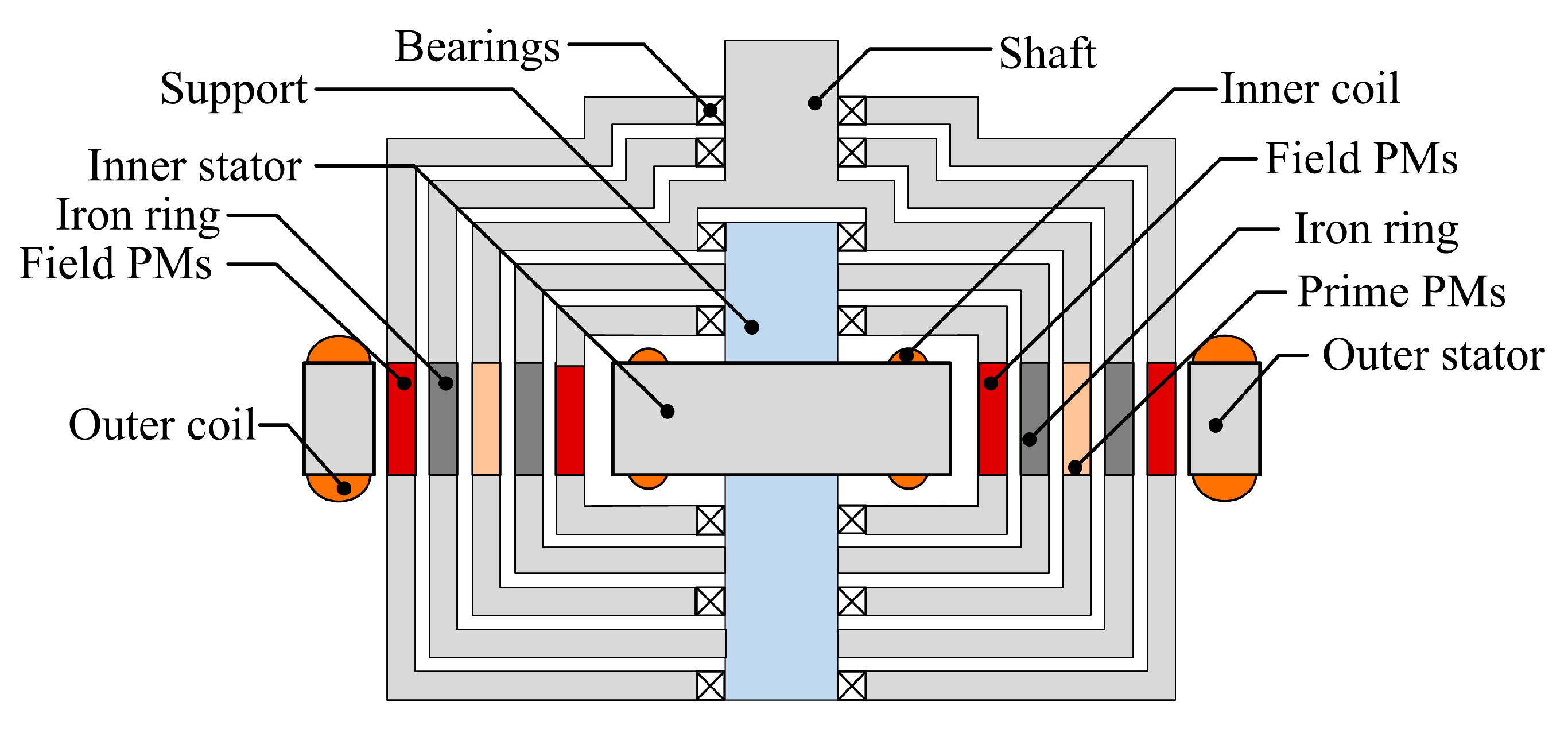
Energies 10 02048 g001
Figure 2. Mechanical structure of double-stator magnetic geared permanent magnet generator.
Energies 10 02048 g002
Figure 3. Magnetic flux plot of the generator quarter section by 2D FEM on load: (a) Magnetic flux lines distribution; (b) Magnetic flux density distribution.
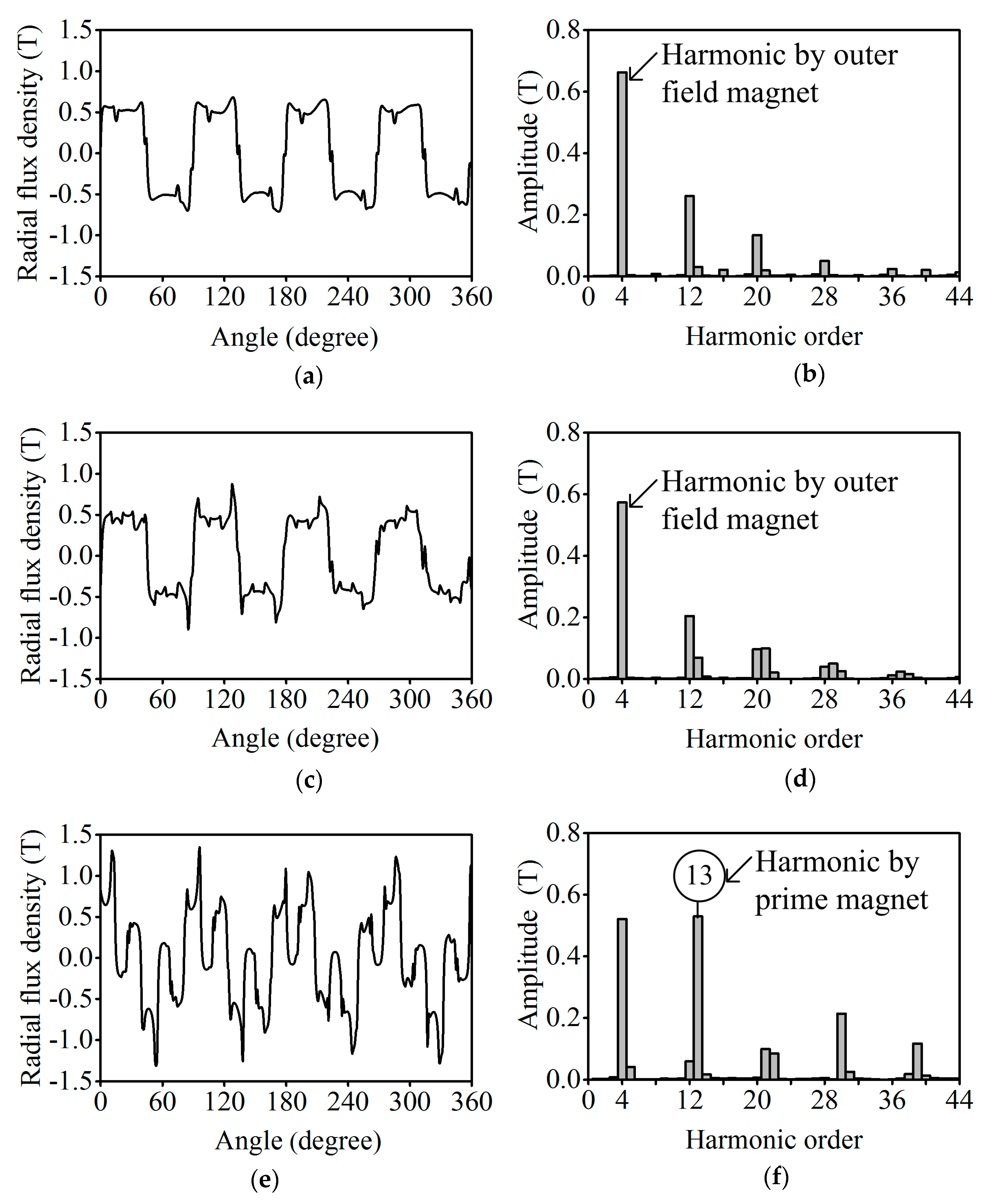
Energies 10 02048 g003
Figure 4. The outer magnetic gear flux density characteristics: (a) Flux density between outer pole-pole ring and prime PM; (b) Fast Fourier Transform of (a); (c) Flux density between outer PM and outer pole-pole ring; (d) Fast Fourier Transform of (c); (e) Flux density between outer PM and outer stator; (f) Fast Fourier Transform of (e).
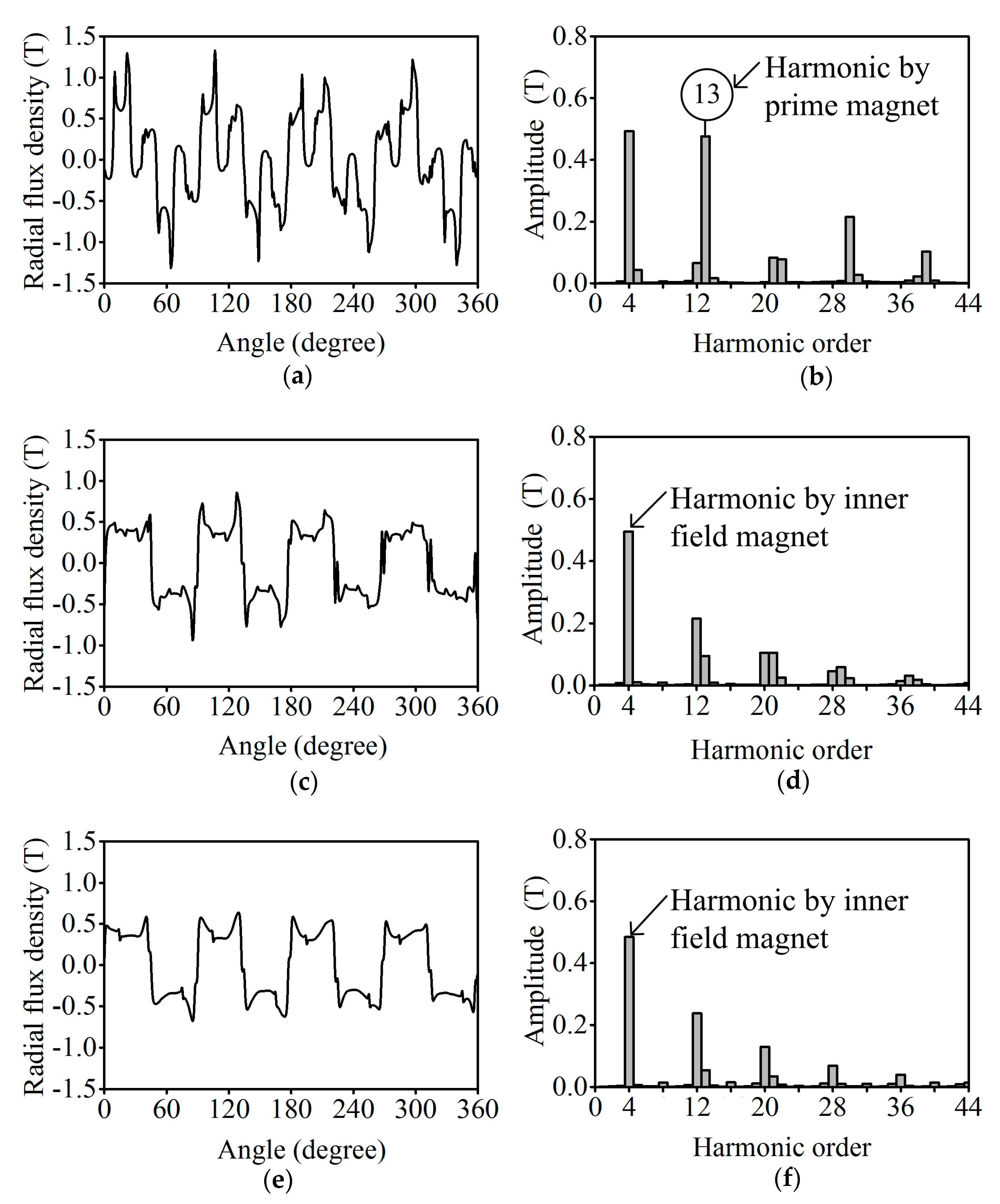
Energies 10 02048 g004
Figure 5. The magnetic gear flux density characteristics in middle of three inner air-gaps: (a) Flux density between inner stator and inner field PM; (b) FFT from (a); (c) Flux density between inner field PM and inner iron ring; (d) FFT from (c); (e) Flux density between inner iron ring and prime PM; (f) FFT from (e).
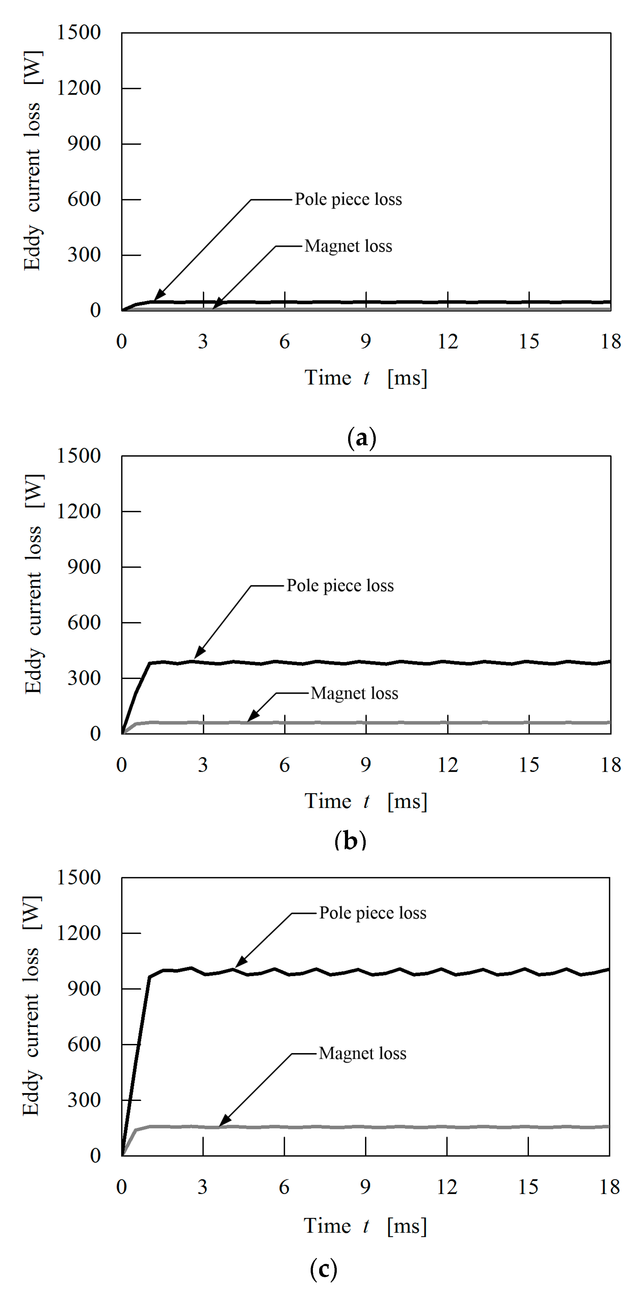
Energies 10 02048 g005
Figure 6. Magnets and pole piece eddy current losses with resistive load of 31 Ω at various speeds: (a) Prime speed of 100 rpm; (b) Prime speed of 300 rpm; (c) Prime speed of 500 rpm.
Energies 10 02048 g006
Figure 7. Core and copper losses as a function of resistive load at various speeds: (a) Core losses; (b) Copper losses; (c) Core and copper losses.
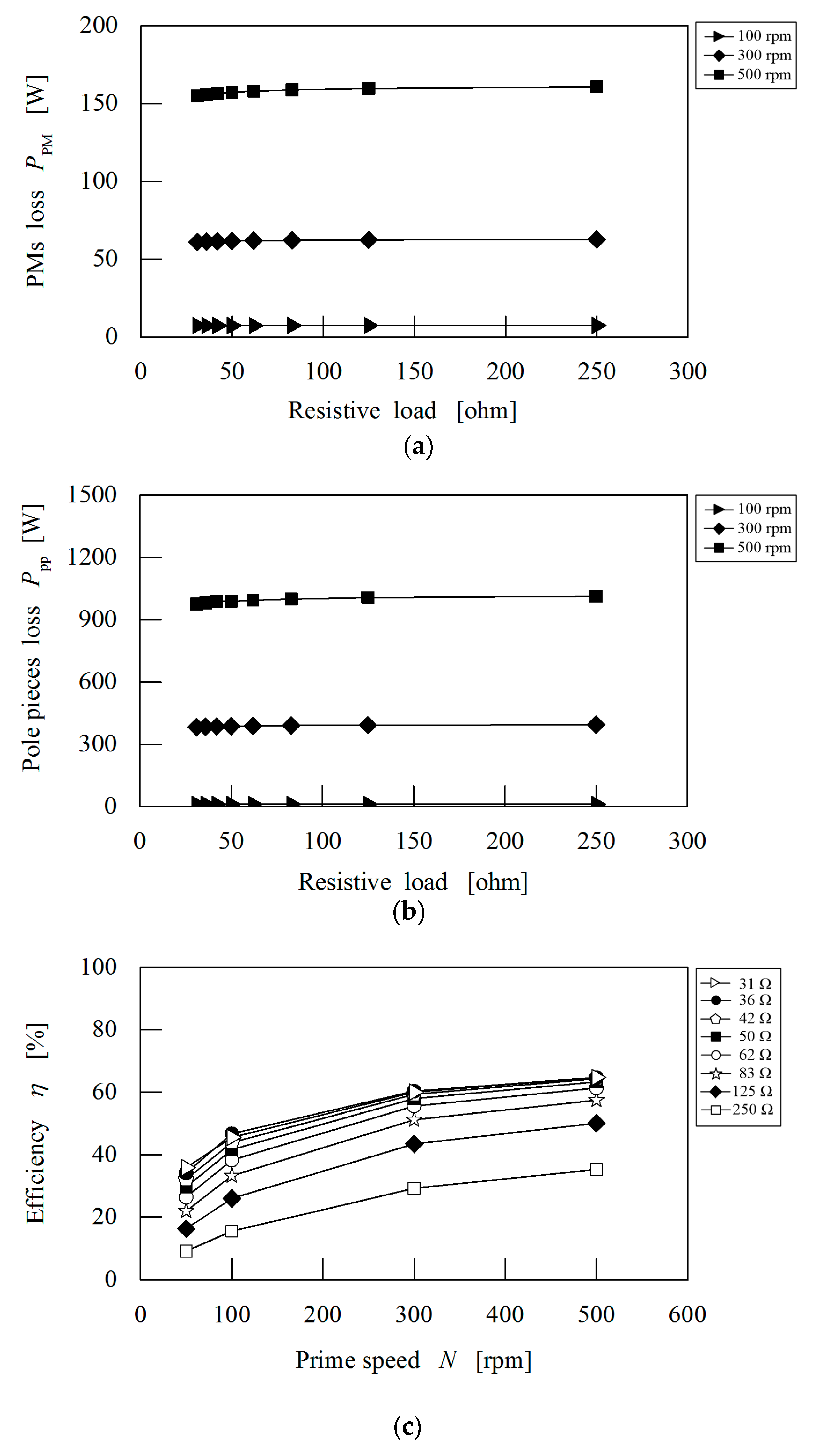
Energies 10 02048 g007
Figure 8. Permanent magnets and pole piece losses as a function of resistive load at various speeds with efficiency: (a) Permanent magnets losses; (b) Pole piece losses; (c) Efficiency.
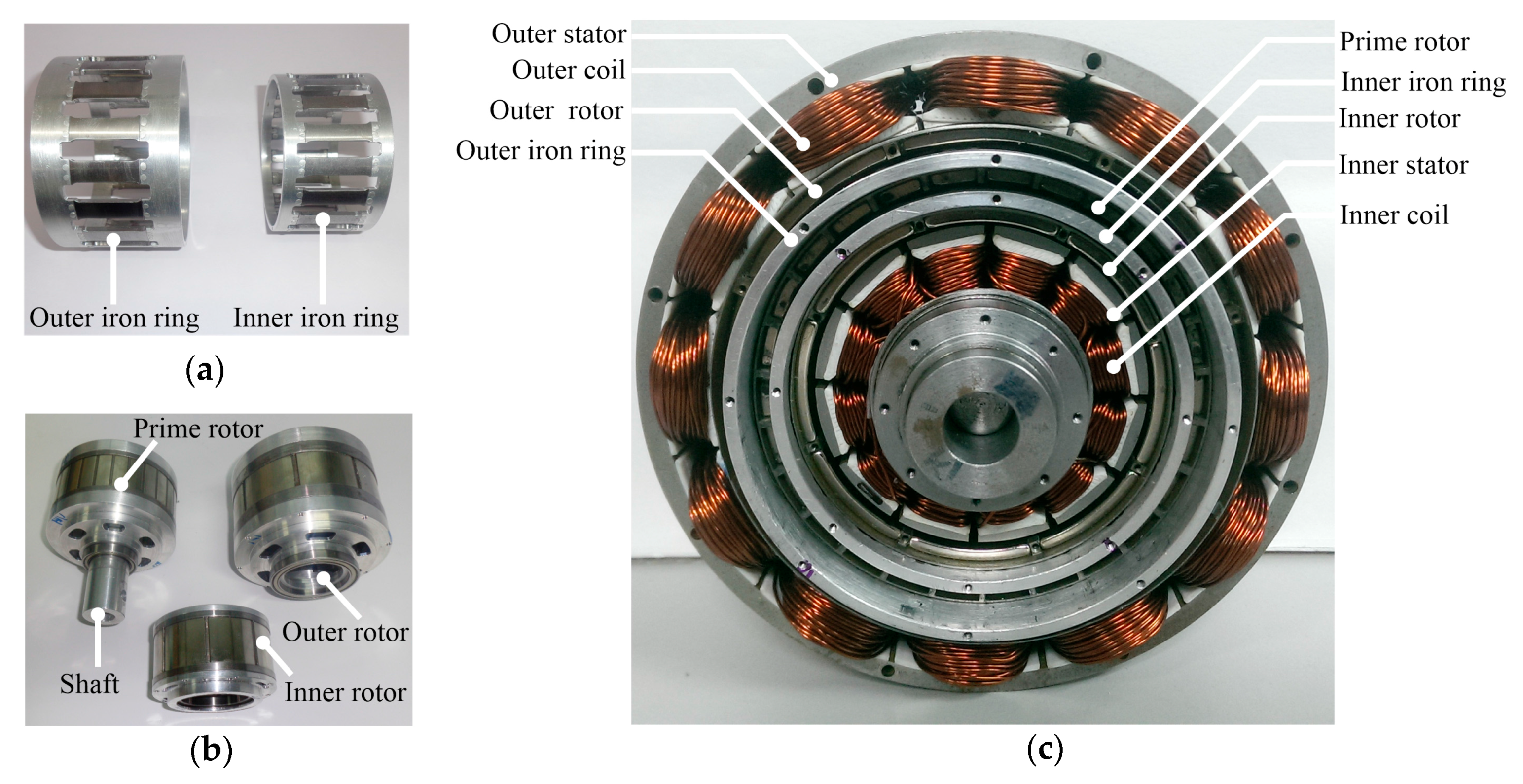
Energies 10 02048 g008
Figure 9. The fabricated components and assembled prototype generator: (a) Iron rings; (b) PM rotors; (c) Assembled prototype.
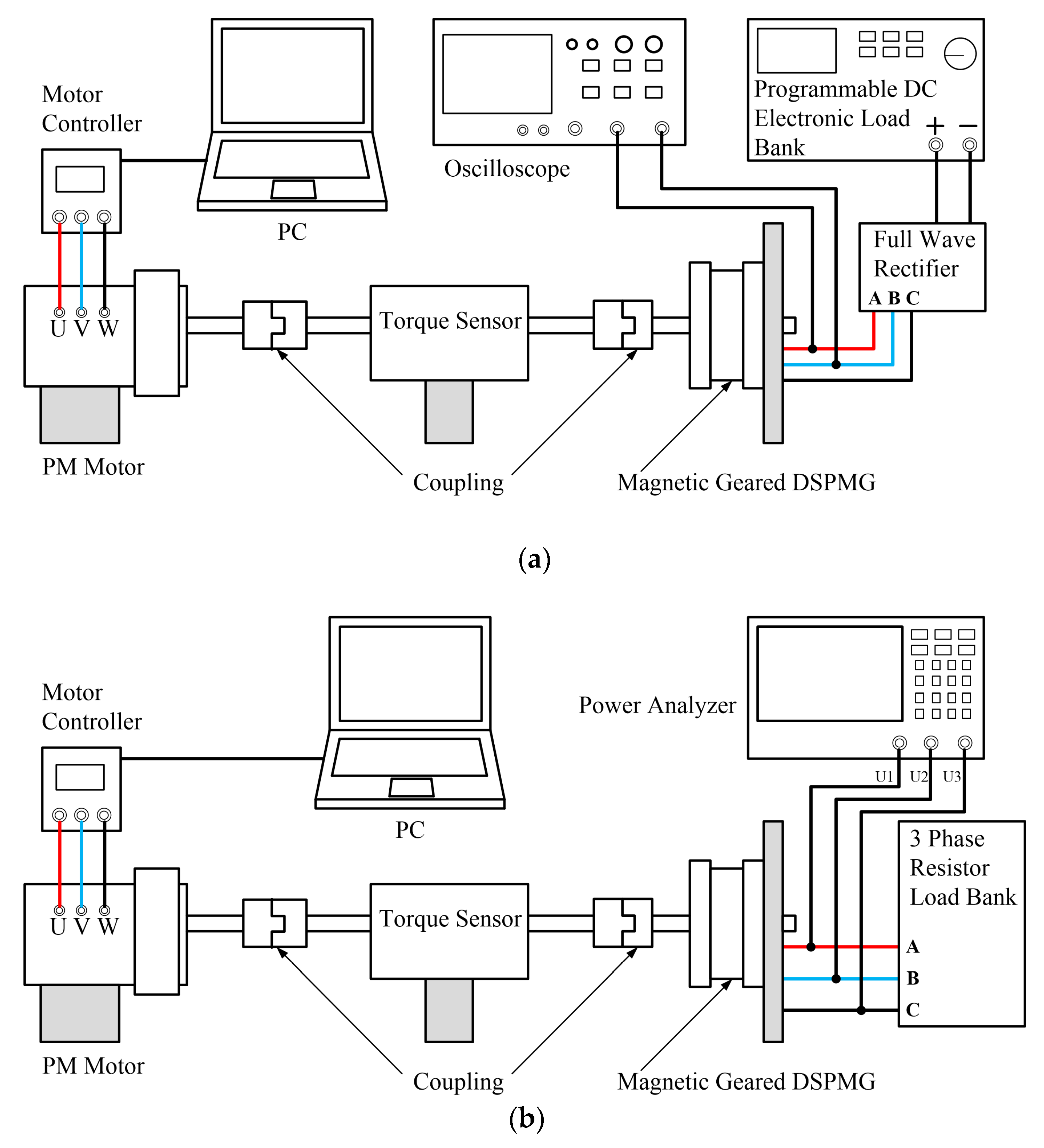
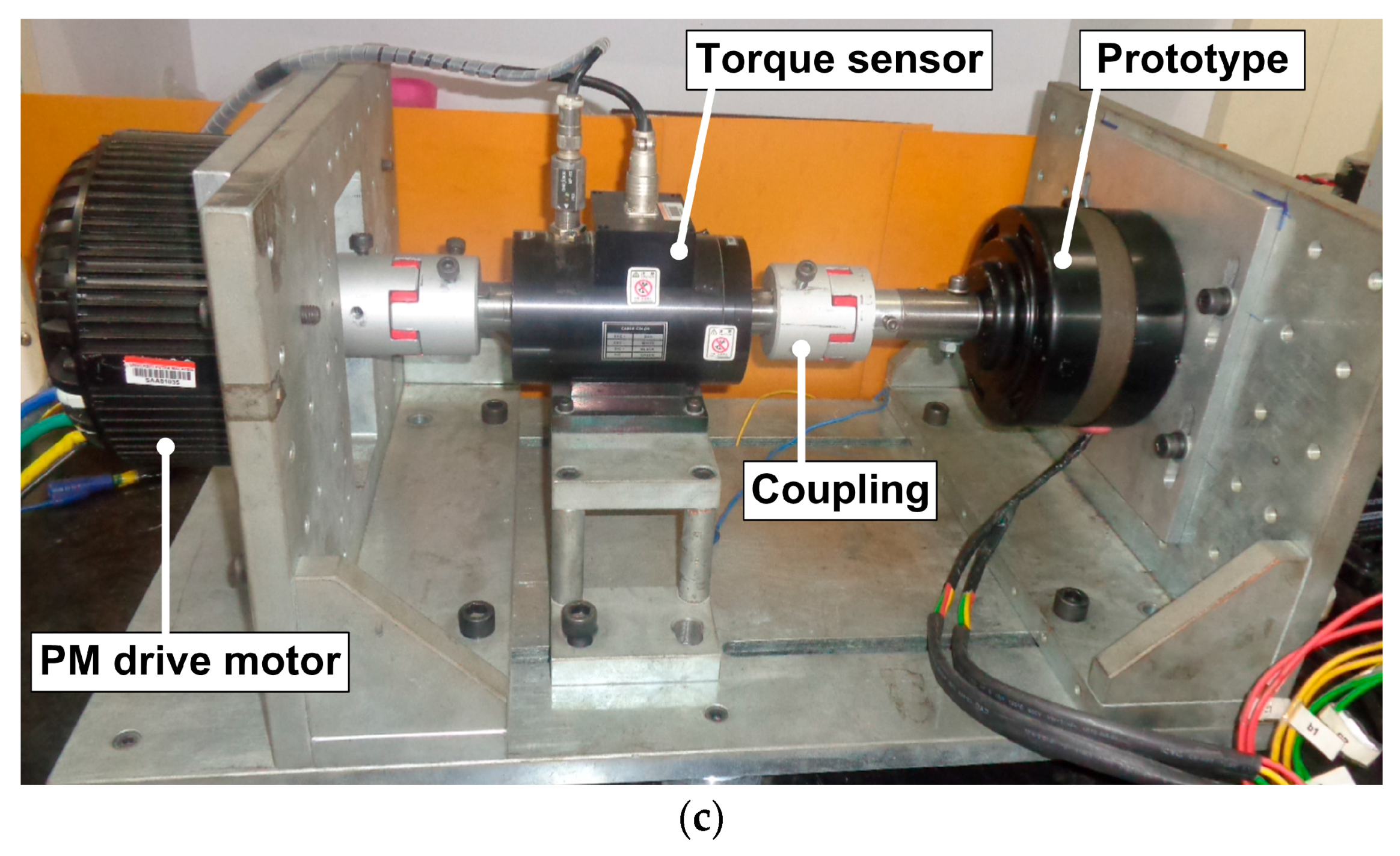
Energies 10 02048 g009
Figure 10. Experimental setup and test rig: (a) DC power measurement configuration; (b) AC power measurement configuration; (c) Prototype in test rig.
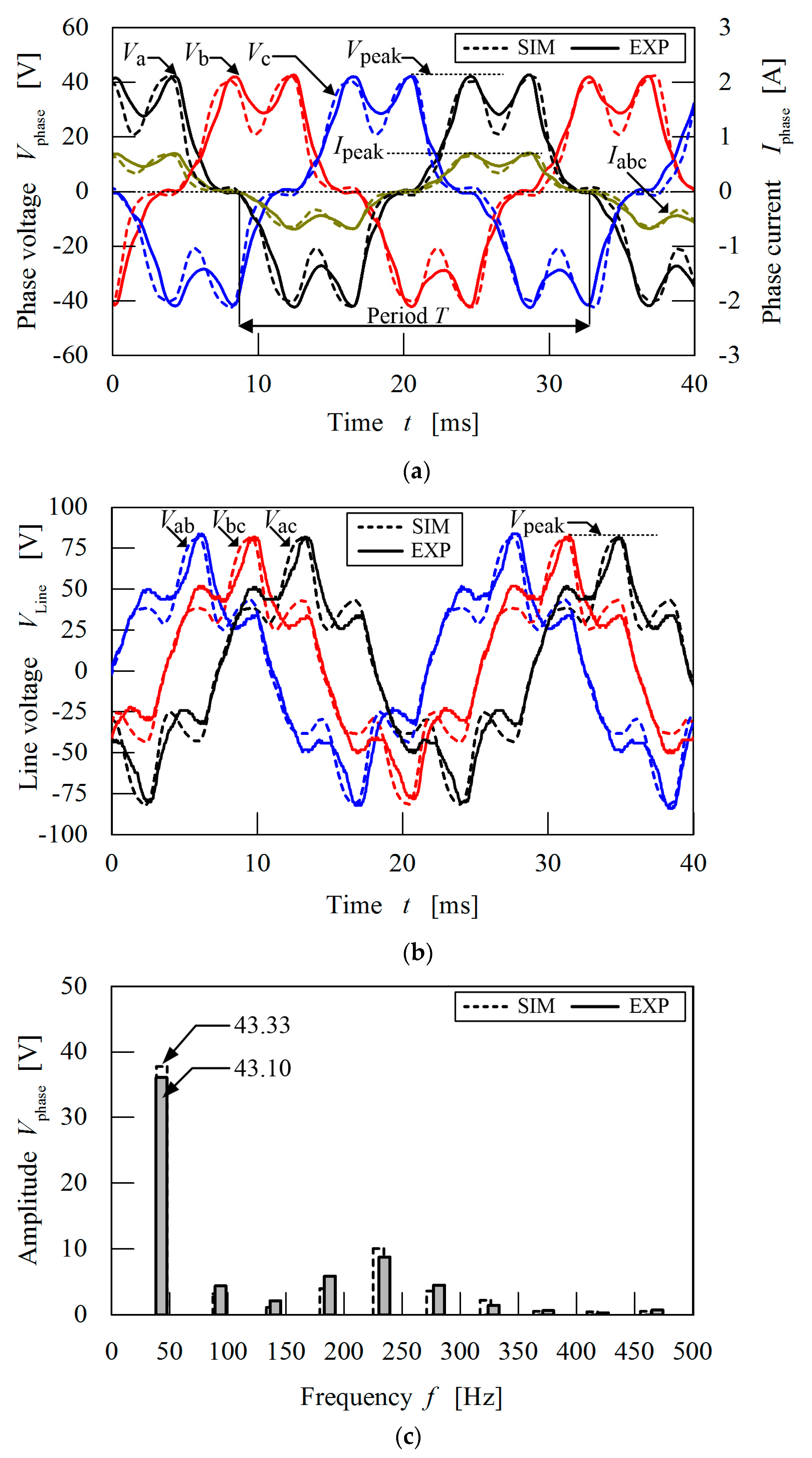
Energies 10 02048 g010aEnergies 10 02048 g010b
Figure 11. Comparison of simulated and measured output three-phase voltage and current from generator with load of 62 Ω at prime rotor speed = 200 rpm: (a) Three-phase voltage and current waveforms; (b) Line voltage waveform; (c) Fast Fourier Transform of simulated and measured three-phase voltage waveform.
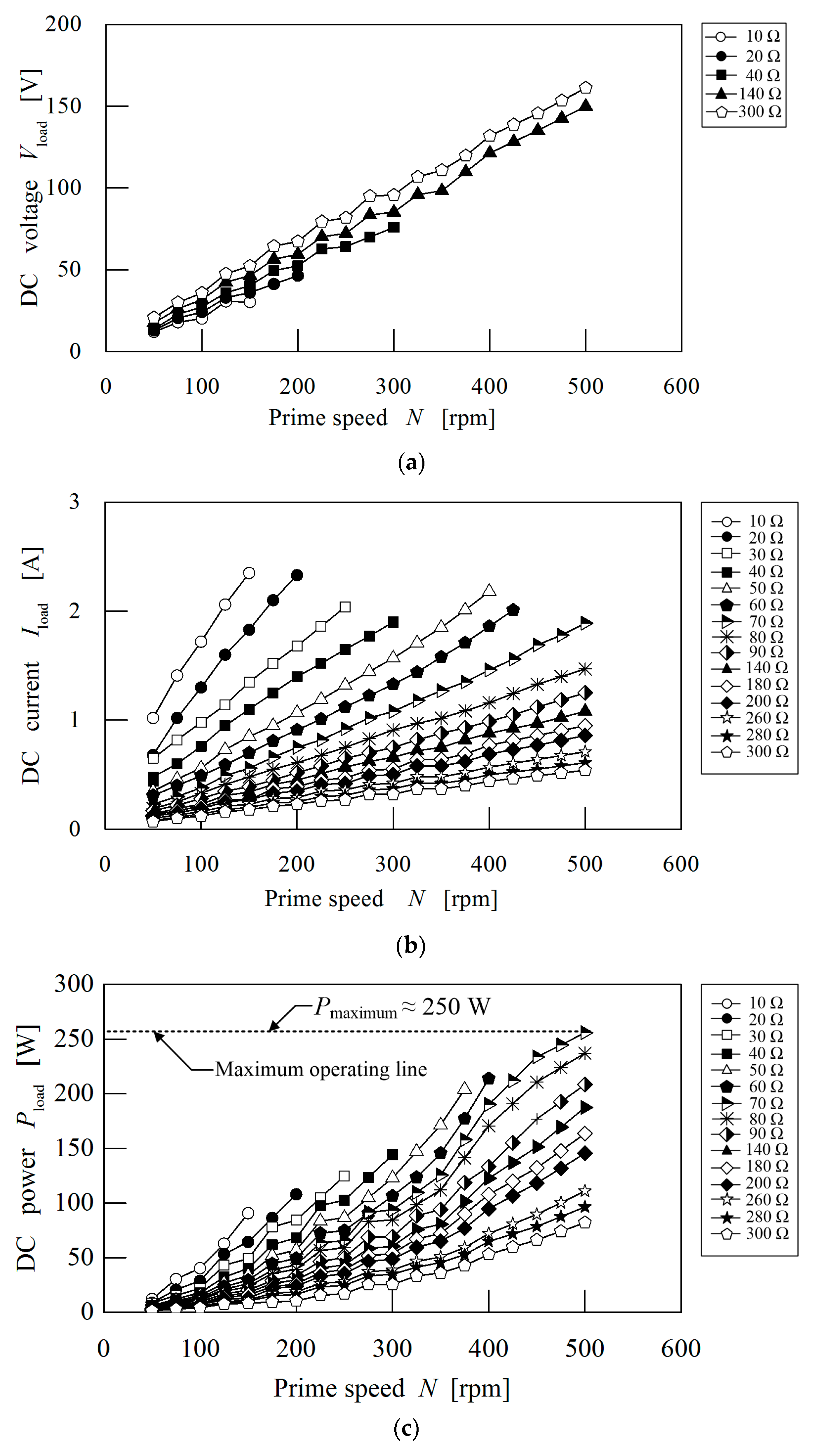
Energies 10 02048 g011
Figure 12. Measured DC voltage/current/power vs. speed characteristics at various loads: (a) DC voltage vs. speed; (b) DC current vs. speed; (c) DC power vs. speed.
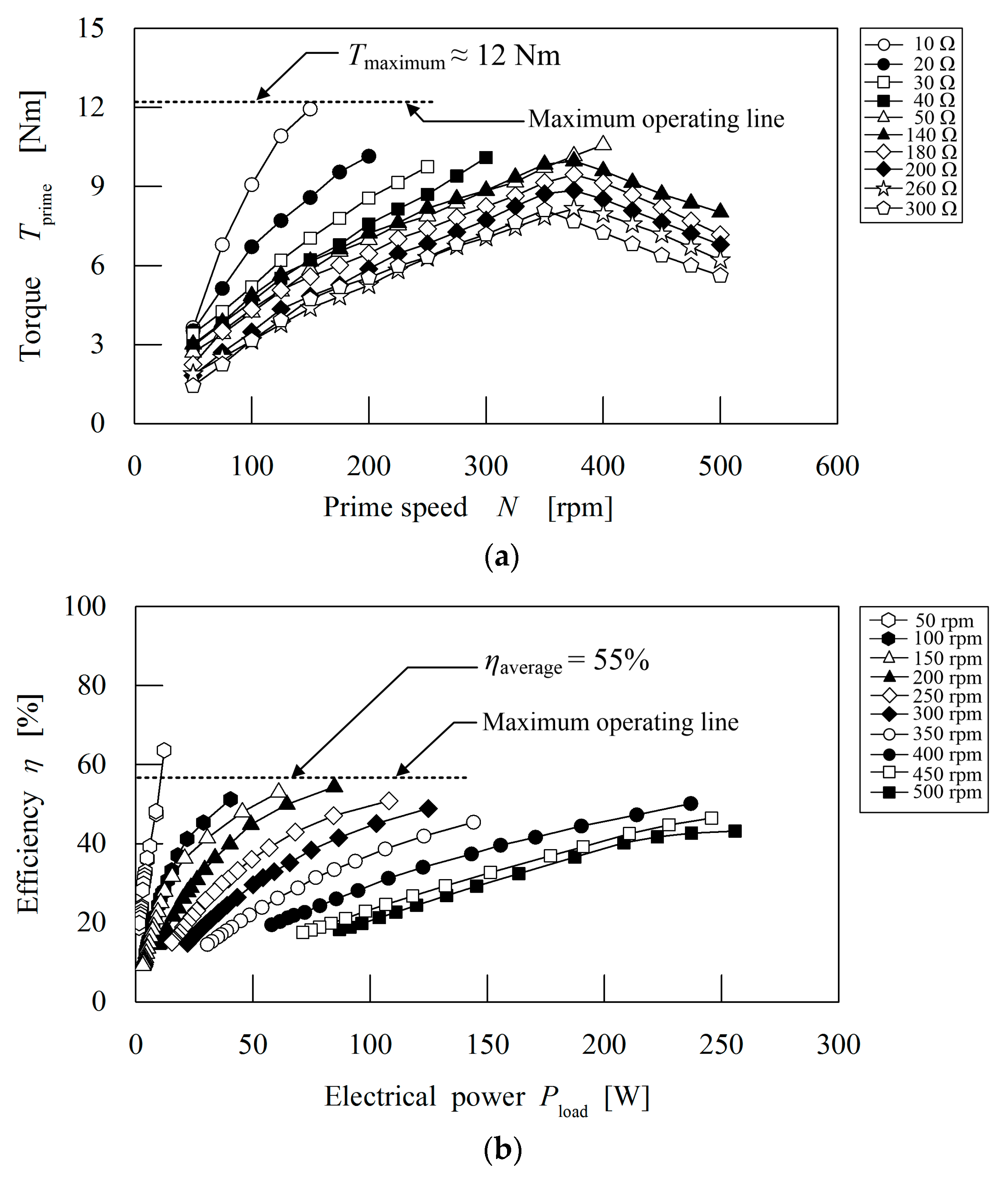
Energies 10 02048 g012
Figure 13. Measured torque and efficiency vs. speed/electrical power characteristics at various loads: (a) Torque vs. speed; (b) Efficiency vs. electrical power.
Energies 10 02048 g013
Figure 14. Measured AC voltage/current/power vs. speed characteristics at various loads: (a) RMS voltage vs. speed; (b) RMS current vs. speed; (c) Active power vs. speed.
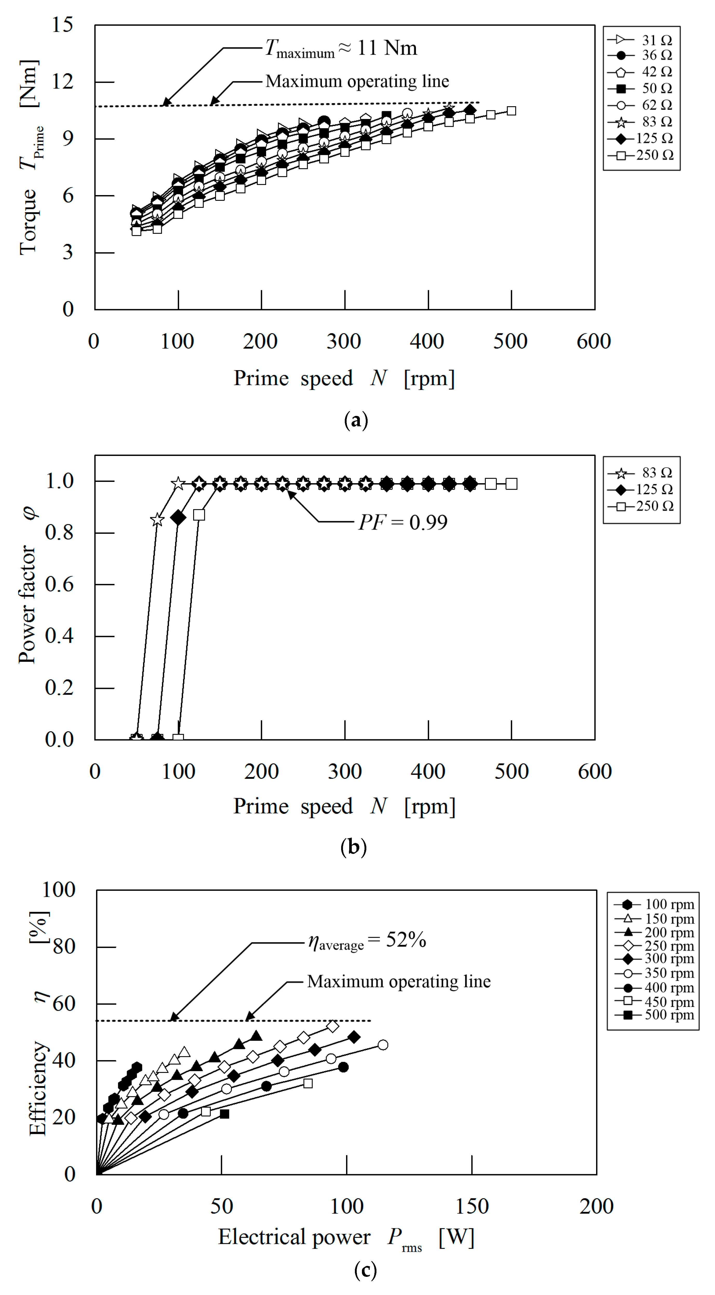
Energies 10 02048 g014
Figure 15. Torque/Power factor/Efficiency vs. speed characteristics at various loads: (a) Torque vs. speed; (b) Power factor vs. speed; (c) Efficiency vs. electrical power.
Energies 10 02048 g015
Table 1. Design specifications of the proposed machine.
ParameterDimension
Outer and inner airgap lengths1.0 mm
Outer stator outside diameter151.2 mm
Outer stator inside diameter116.6 mm
Inner stator outside diameter74.6 mm
Inner stator inside diameter14.0 mm
Axial length30.0 mm
No. of outer stator slots12
No. of inner stator slots12
No. of outer and inner PMs8
No. of prime PMs26
No. of outer and inner pole pieces17
No. of phases3
No. of outer stator slots per pole per phase1/2
No. of inner stator slots per pole per phase1/2
Cogging torque factor1
Magnetic gear ratio3.25
Table 2. Material properties.
ComponentMaterial
MagnetsNd-Fe-B-38H
Pole piecesSS400
RotorsSS400
Stators50H800 Laminated steel sheet
Pole piece end ringsAluminum
Table 3. Coil winding specifications.
ParameterValue
Diameter of wire0.80 mm
Number of turns outer coil75
Number of turns inner coil31
Resistance per phase outer coil1.70 Ω
Resistance per phase inner coil0.80 Ω
Phase connectionStar
Table 4. Outer air-gap flux density performance of the magnetic gear.
ParameterValue
Main harmonic between prime PM and outer iron ring4
Main harmonic between outer iron ring and outer field PM4
Main harmonic between outer field PM and outer stator13
Calculated magnetic gear ratio3.25
Ratio of main harmonics 4 and 133.25
Table 5. Inner air-gap flux density performance of the magnetic gear.
ParameterValue
Main harmonic between inner stator and inner field PM4
Main harmonic between inner field PM and inner iron ring4
Main harmonic between inner iron ring and prime PM13
Calculated magnetic gear ratio3.25
Ratio of main harmonics 4 and 133.25
Table 6. Summary of measured power characteristics for prototype magnetic geared generator.
ParameterValue
Maximum output DC power≈250 W
Maximum output AC power≈120 W
Maximum torque on DC load≈12 Nm
Maximum torque on AC load≈11 Nm
Power factor0.99
Table 7. Comparison of performance characteristics for prototype magnetic geared generator.
ParameterCalculatedMeasured
Maximum power efficiency60%55%
Prime PM rotor speed200 rpm200 rpm
Field PM rotor speed650 rpm646 rpm
Gear ratio3.253.23
Frequency of voltage43.33 Hz43.10 Hz
Time period of voltage23.10 ms23.20 ms
Phase peak voltage≈42 V≈42 V
Phase peak current0.69 A0.66 A
Line peak voltage≈87 V≈86 V

