LED Uniform Illumination Using Double Linear Fresnel Lenses for Energy Saving


Department of Information and Communication Engineering, Myongji University, San 38-2 Nam-dong, Yongin 449-728, Korea
*
Authors to whom correspondence should be addressed.
Energies 2017, 10(12), 2091; https://doi.org/10.3390/en10122091
Submission received: 9 November 2017
/
Revised: 4 December 2017
/
Accepted: 6 December 2017
/
Published: 11 December 2017
(This article belongs to the Special Issue Solid State Lighting)
Abstract
:We present a linear Fresnel lens design for light-emitting diode (LED) uniform illumination applications. The LED source is an array of LEDs. An array of collimating lens is applied to collimate output from the LED array. Two linear Fresnel lenses are used to redistribute the collimated beam along two dimensions in the illumination area. Collimating lens and linear Fresnel lens surfaces are calculated by geometrical optics and nonimaging optics. The collimated beam output from the collimating lens array is divided into many fragments. Each fragment is refracted by a segment of Fresnel lens and distributed over the illumination area, so that the total beam can be distributed to the illumination target uniformly. The simulation results show that this design has a compact structure, high optical efficiency of 82% and good uniformity of 76.9%. Some consideration of the energy savings and optical performance are discussed by comparison with other typical light sources. The results show that our proposed LED lighting system can reduce energy consumption five-times in comparison to using a conventional fluorescent lamp. Our research is a strong candidate for low cost, energy savings for indoor and outdoor lighting applications.
1. Introduction
In recent years, the use of light-emitting diodes (LEDs) for lighting has become more popular because of their energy saving, long lifespan, compact volume, high color-rendering index and environmental benefits [1,2]. Although LED manufactures and leading suppliers have celebrated the advantages of LEDs in the industry publications and their catalogues [3], the semi-spherical radiation pattern of LEDs is a drawback that renders them rarely used directly for illumination purposes that require high uniformity. To solve this problem, some secondary optical elements are utilized to redistribute light from the LED source to the target position efficiently and uniformly.
Recently, many researchers have been concentrating on the development of the LED diffusers, which can improve the cost-efficiency, energy savings and uniform distribution of LED lighting systems. In most cases, the secondary optical component is designed for a single LED [2]. This element design involves several basic methods. Shi et al. presented the design of an LED rectangular uniform illumination lens based on the freeform optics, the lighting-energy conservation law, the edge-ray principle and Snell’s law [4]. Rabl et al. proposed a 3D reflector for uniform far-field illumination. This reflector was designed using tailored edge-ray theory [5]. A combination of a Fresnel lens and a micro-lens array for LED illumination was proposed by Wang et al. [6]. The Fresnel lens for the collimation of LED irradiation and the micro-lens array for the uniform distribution of the collimated beam were designed according to geometrical optics and nonimaging optics. A group from Yonsei University, Korea, improved the illuminance uniformity, color uniformity and flux efficiency of LED illumination by using a modified Fresnel lens with an optimized groove angle [7]. However, most methods that use secondary optics design involve complex calculations, which result in complicated and costly LED lens designs. In addition, because of the limited optical power output from a single LED, many LED lighting modules are required to illuminate a large area, and this requirement increases the cost of the total illumination system and installation. Another approach is using an LED array as a light source. For the purpose of illumination, achieving a good uniform distribution of LED array sources is important. Zhouping Su’s group proposed a numerical optimization method for designing an LED array for achieving a good uniform illumination distribution on the target plane. A simulated annealing algorithm is used to optimize an LED array arrangement. In a report from Moreno et al. [8], different array configurations with optimum LED-to-LED spacing were used to obtain a uniform distribution. The optimum LED-to-LED spacing was achieved using the analytical method This group also designed a spherical LED array, which could distribute LED light uniformly over a large area [9]. Whang presented a method for designing an LED array with an arbitrary view angle for a uniform illumination distribution [10]. Zong Qin studied the uniform illumination condition for an LED array with a large view angle [11]. Most methods for the uniform illumination of an LED array are based on the calculation and optimization of LED positions, intensities and emitting directions. Although the advantage of these methods is that they can achieve high optical efficiency because they do not use any secondary optics for redistribution, they are only suitable for some specific purposes because of the great complexity of the analytical method. These methods are difficult for wide use in indoor and outdoor lighting, which requires flexibility in design. Therefore, these studies have not been commercialized successfully on the market to date.
In this study, we propose an alternative approach to the uniform illumination of an LED array by designing simple secondary optics components. The LED bare chips are integrated into an array using chip-on-board (COB) technology. An array of collimators is placed on the top LED array to collect and collimate the light output from an LED array. The collimator is a plano-convex lens, which is developed with a special aspherical convex design using the freeform optics design method. The distributor was used to redistribute the LED light uniformly throughout the illumination area. The distributor was composed of two linear Fresnel lenses placed perpendicularly to each other. The linear Fresnel lens was designed by using the simultaneous multiple surface (SMS) method and the commercial MATLAB software. The simplicity and the flexibility of the design method and system configuration enable this research to be applied for various lighting purposes.
The remainder of the paper is organized as follows: Section 2 discusses the LED illumination system design. In Section 3, an LED illumination system is modeled by using the LightToolsTM software (Synopsys Inc., San Jose, CA, USA) to analyze the performance of this system. This section also discusses the applications for indoor and outdoor illumination purposes. The conclusions are presented in Section 4.
2. LED Uniform Distribution System Design
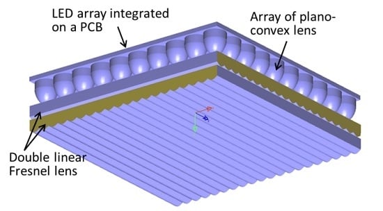
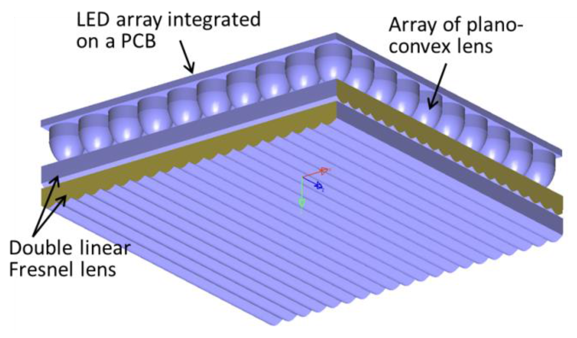
The design for a uniform LED illumination system is presented in this section. Our goal is to design a lighting system with a simple shape and a low fabrication cost using an array of LEDs. By constraining the design to be compatible with a simple fabrication process such as the molding method, we propose a novel uniform illumination system for an LED array source by using a freeform plano-convex lens as the light collimator and a double layer of linear Fresnel lenses as the uniform light distributor. The physical layout of the system is shown in Figure 1. The upper layer is a rectangular array of LED chips integrated on a printed circuit board (PCB) using COB technology. The light emitted from the LED array is collimated by the collimation layer, which is an array of plano-convex lenses. Most conventional LED diffusers, which are reflectors or lenses, do not provide an effective solution to redistribute the collimated beam at the illumination target. In this study, we propose the design of the double layers of linear Fresnel lenses to spread the collimated beam for uniform illumination. The details of the system such as optical elements and their parameters are discussed below.
2.1. LED Array
In our proposed system shown in Figure 1, the array of collimators (plano-convex lenses) is attached to collimate the LED output light from an array of LED chips. It is difficult to make an array of LED using the conventional LED chips, which have an end capsule placed right on top of the emitting surface. The LED COB technology has been developed recently, and it gives us a solution to solve this problem. In this study, we optimized certain aspects of the design space using the parameters from the commercially available LED COB of ProPhotonix Company (Cork, Ireland). The LED COB technology is a method of mounting a bare LED chip in direct contact with the substrate to fabricate LED arrays. COB technology allows a high packing density because of the small size of the LED chip, thus resulting in higher intensity and easy coupling with the collimator. We employed a rectangular array of LEDs on board to couple with the collimator layer.
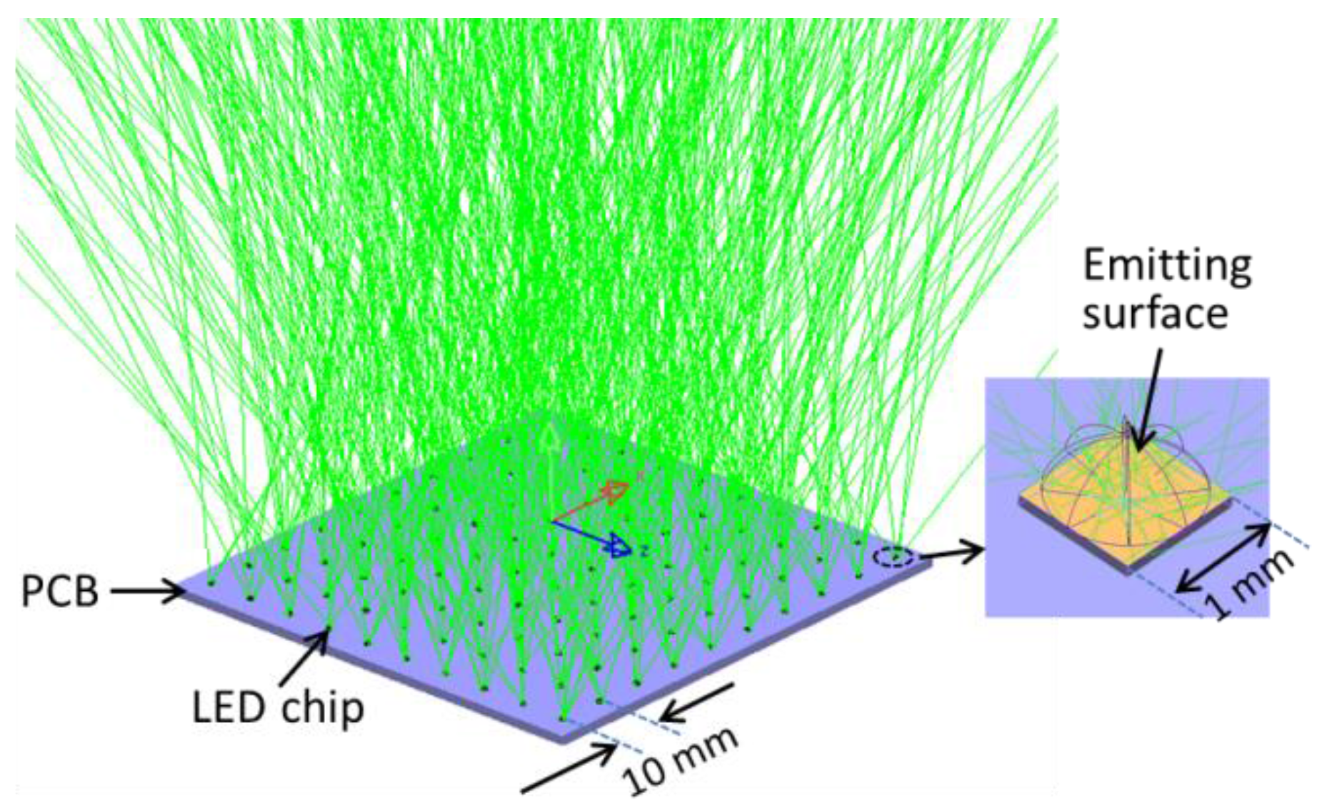
In our optical design and simulations, 100 LED chips with a size of 1 mm × 1 mm are arranged in a rectangular array with a lattice of l = 10 mm, as shown in Figure 2. Therefore, the total length of the system is 100 mm × 100 mm. We use LightToolsTM to model the LED array with ray tracing. This LED array is used for the design of the collimator and the distributer.
2.2. Collimator
The collimator is an optical element that collects the rays from the LED source and deflects them to become parallel rays. A typical collimator may be constructed simply by a parabolic mirror or lens, and the LED source is positioned at its focal point. These types of collimators only work with a light source that has a small view angle. A typical LED with a large view angle of 120° cannot be collimated efficiently by these conventional collimators. Therefore, we propose the technique of designing a plano-convex lens using freeform optics. The design methodology of the freeform lens is described in Figure 3.
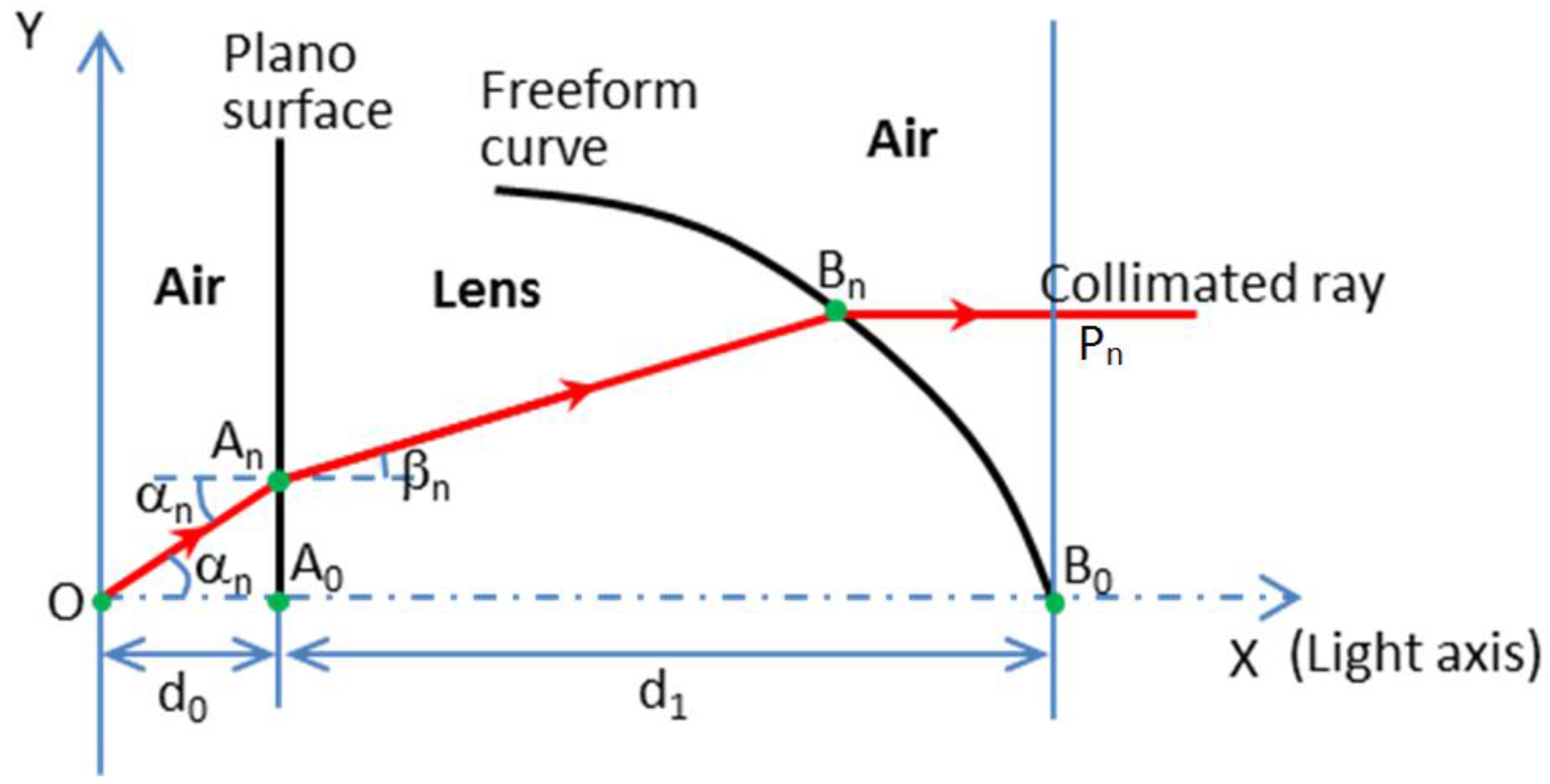
As shown in Figure 3, the plano-convex lens is composed of two surfaces: a plano-surface and a freeform surface. The plano-convex lens in our study is rotationally symmetric. In a rotationally-symmetric system, only 2D coordinates are discussed. Suppose that an LED chip is a point source. The LED is in the air with the refractive index n0, and the collimation lens made of plastic has the refractive index n1. The LED source is located in the original point O. Ray OAn is an incident ray to the plano-surface with an incident angle of αn. OAn is refracted to ray AnBn at point An on the flat surface of the lens. According to Snell’s law of the following Equation (1),
The LED source emits a spherical wavefront. After the spherical wavefront is refracted by the freeform surface, it becomes a plane wavefront. All the light rays that emit from the LED have the same optical path from the source to the wavefront. According to the conservation of optical path obtained by Equation (2),
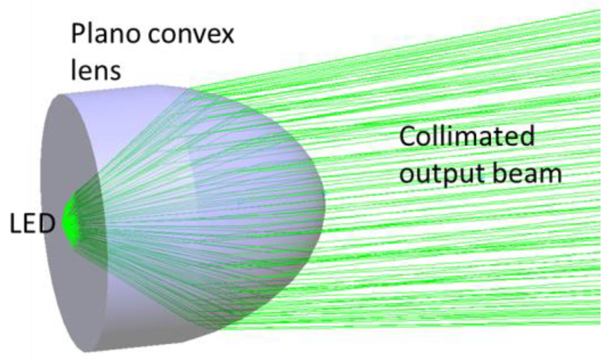
where OA0 is the initial incident ray along the x axis and A0B0 is the refractive ray by the plano-surface. As the incident angle is zero degrees, it goes straight. OA0 = d0 is the distance from the LED to the plano-surface, and A0B0 = d1 is the length of the plano-convex lens. All the points on the freeform curve can be calculated by solving Equations (1) and (2). Therefore, the entire freeform curve can be obtained by collecting the coordinates of these points. The whole lens surface was built by revolving the 2D curved profile in the 3D modeling software (LightToolsTM). Figure 4 shows a solid model of this freeform plano-convex lens with ray tracing. Table 1 listed all the design parameters for a collimator. If the light source is a point source, the proposed collimator can collimate the beam perfectly. However, in this study, the LED chip (1 mm × 1 mm) cannot be considered a perfect point source. Therefore, the output beam from the collimator is not a parallel beam; it has a small divergent angle. The travelling of the beam, which is emitted from a small source, passing through the collimator is very complicated and cannot be calculated by theory. For this situation, the simulation using LightTools is conducted to calculate the divergence of the output beam. We obtained an output beam divergence of 7.5°. The effect of the non-ideal collimated beam on the efficiency and uniformity of the illumination system is discussed in Section 3.
A collimating lens for an LED light source is an essential device that is widely used in lighting engineering. Many methods to design and fabricate the collimator can be found in the literature on LED lighting engineering, such as in [6,12]. However, for illumination purposes, the collimation requirement is not high, and therefore, a simple structure and a low fabrication cost are preferred. The proposed plano-convex lens design using the freeform optics technique satisfies all these requirements. The fact that some similar products are available on the market with a low price [13] shows that our proposed plano-convex lens design is commercially viable. One hundred of the designed plano-convex lenses are arranged in a 10 × 10 array as a collimation layer for the LED array, as shown in Figure 5.
2.3. Linear Fresnel Lens Design
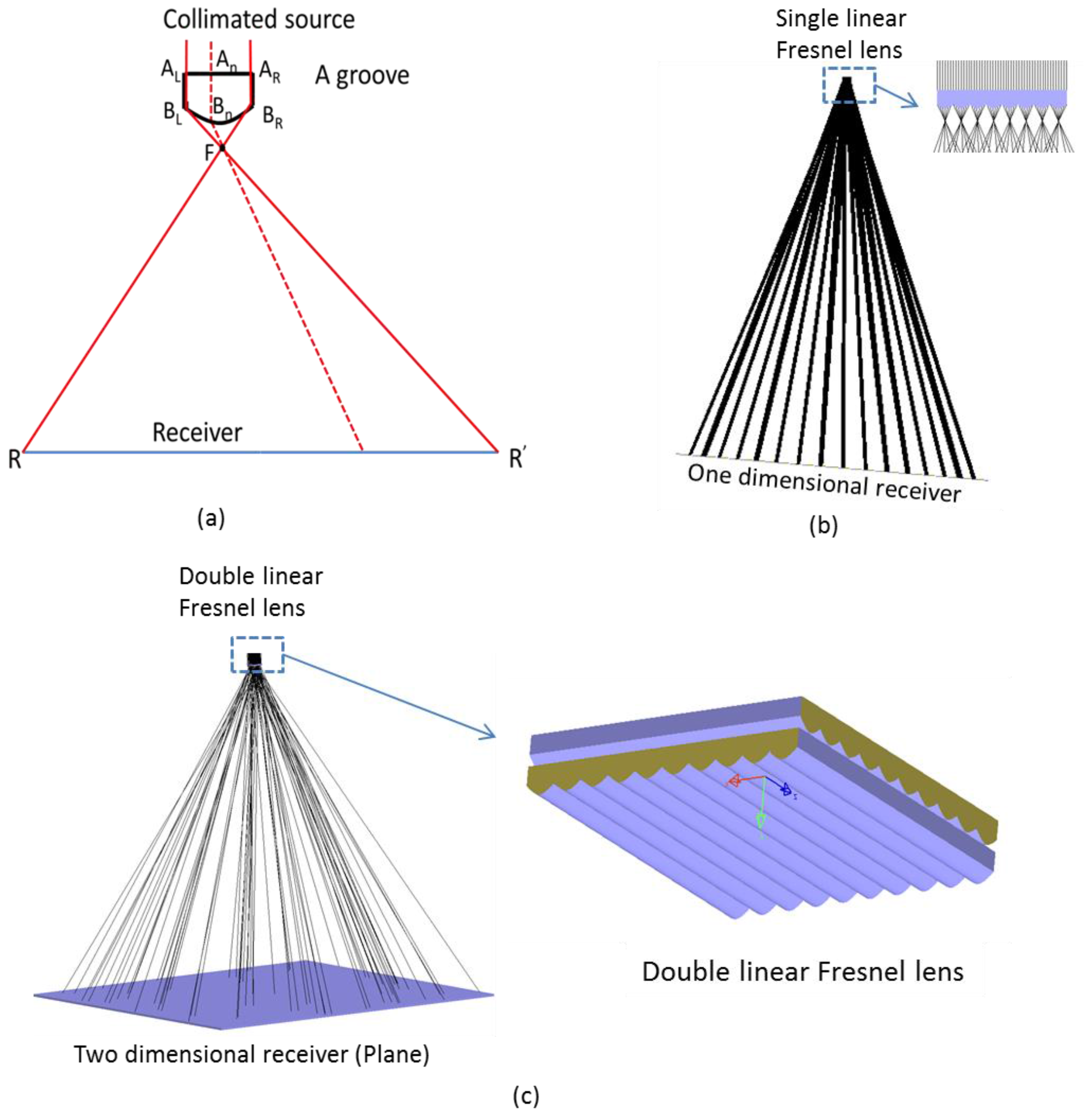
The high-intensity collimated LED beam needs to be distributed uniformly in the receiver for illumination purposes. The uniform distribution of light is a critical issue in solid state lighting. In our case, the light source is small in size (100 mm × 100 mm) with high intensity, and it is a collimated beam of LED light. Most of typical light distributers that are used in LED lighting engineering do not support a redistribution of the collimated beam to the illumination area uniformly. In this research, a uniform illumination distribution in the illumination plane is desired. The special design of a linear Fresnel lens that can spread the collimated beam uniformly is proposed here. The linear Fresnel lens can redirect collimated rays to the expected positions along one dimension. The proposed linear Fresnel lens includes many segments, and each segment is a tiny convex lens. The parallel beam passing through each segment is focused at a very short focal length and spread over the one-dimensional receiver. Two linear Fresnel lenses placed perpendicularly can redirect the collimated light uniformly on a two-dimensional illumination area. Similar to Section 2.2, we applied the SMS method to calculate the curve of the Fresnel lens’s segment. The SMS method for designing nonimaging optical components was developed several years ago and is widely used in solar energy and lighting applications [14]. The design process for one segment is described in Figure 6a. Some initial conditions, including left edge ALBL, right edge ARBR of the segment and the receiver size RR’ are given. The left ray ALBL is deflected to the rightmost of the receiver, R’. Similarly, the right ray ARBR is deflected to leftmost of the receiver, R. Two rays ALR’ and ARR intersect at point F, which is the focal point of a segment. Every ray between ALBL and ARBR must be concentrated at F after they are refracted on the surface of the segment. These rays reach the receiver after passing though F. Therefore, all rays are redistributed over the receiver RR’ after passing through the segment. As all rays are focused on F, they must satisfy the law of optical path length (OPL) conservation; see Equation (3):
where n0, n1 are the refractive indices of air and the Fresnel lens material, respectively. Based on these equations, all coordinates of the segment surface curve are calculated. Profiles of all other segments of the linear Fresnel lens are calculated using the same procedure. Figure 6b shows the performance of a single linear Fresnel lens in a 1D receiver.
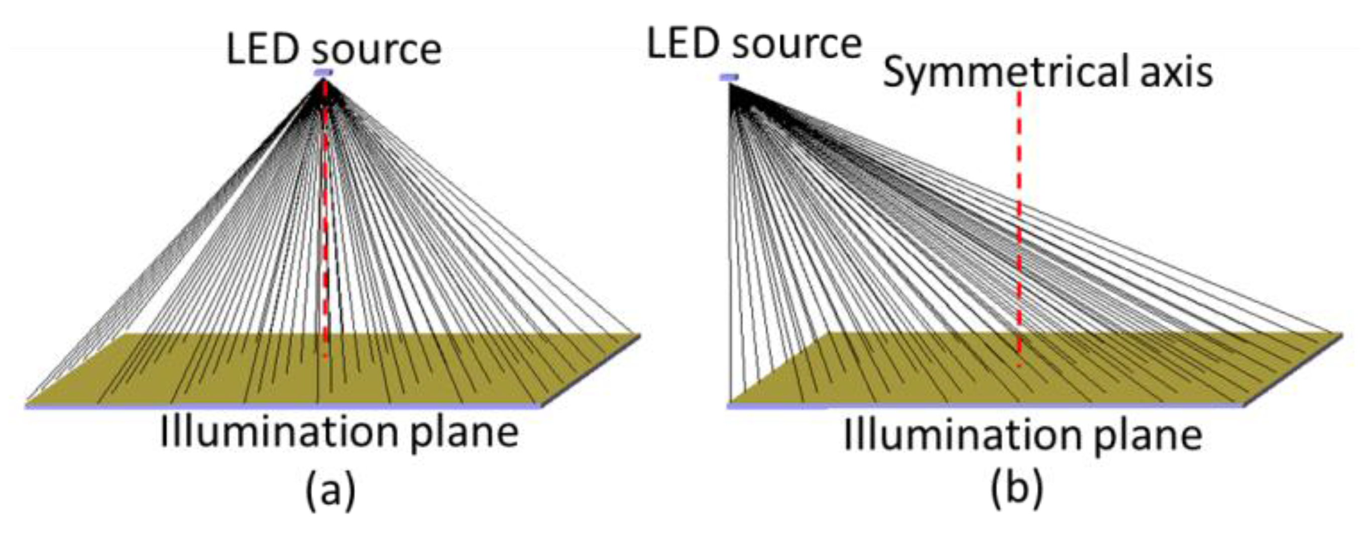
We placed two linear Fresnel lenses perpendicularly to spread the light in two-dimensional illumination areas, as shown in Figure 6c. The exaggeration of Figure 6c is the detail of the double linear Fresnel lens. On the basis of this design method, we built Fresnel design software that can specify the characteristics of double Fresnel lenses by controlling some input conditions, such as positions of the Fresnel lens and illumination plane (receiver), the size of the Fresnel lens, the number of segments in the lens and the size of the illumination plane. This method is flexible because two linear Fresnel lenses are utilized to redistribute light along the horizontal and vertical directions. The size (width and length) of the illumination plane can be changed freely by changing the initial conditions. One other interesting aspect of our design is that it can illuminate the target not only when the light source lies on the symmetrical axis, but also when it is out of the symmetrical axis of the illumination plane, as shown in Figure 7a,b.
3. Simulation Results and Comparison
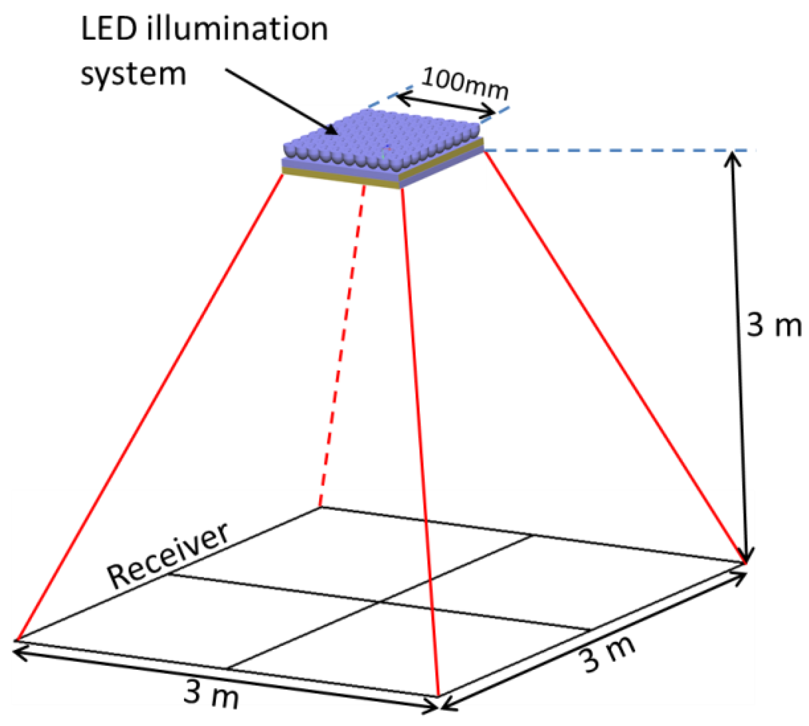
The commercial optical simulation software LightToolsTM is utilized to design and simulate the geometrical structure of the proposed LED lighting system. The structure of the system for simulation is shown in Figure 8. A square shape of lighting is chosen as an example to investigate the performance of the designed lighting system. As described above, the LED illumination system includes an array of LED chips, an array of plano-convex lens as a collimator and a double linear Fresnel lens as a light distributor. Lambertian LED chips are used in the simulations. Each LED generates 50 lm; therefore, the total flux of the LED array is 5000 lm. In the designed system, the Fresnel lens and collimated source are made of poly methyl methacrylate (PMMA). The double Fresnel lens for producing uniform illumination distribution in a 3 m × 3 m receiver is designed. The receiver is located 3 m away from the light source. Efficiency and uniformity are important characteristics of the lighting effect.
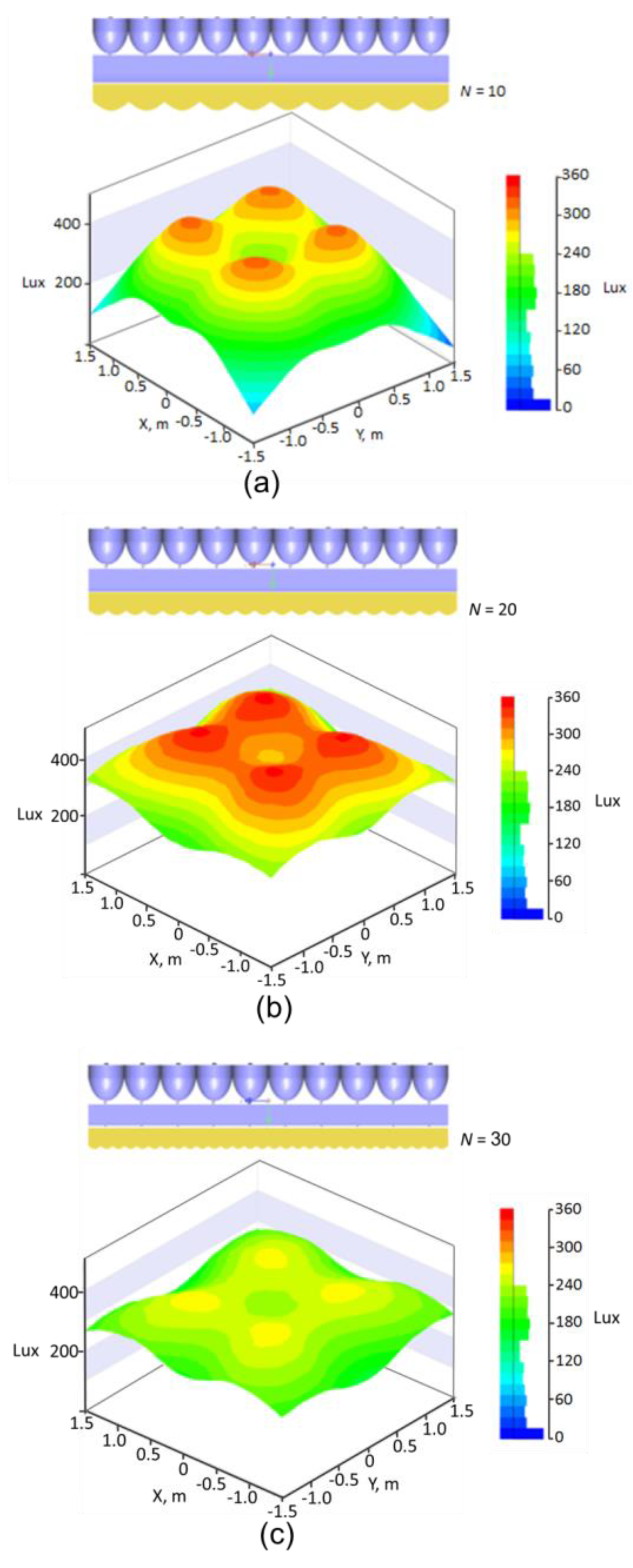
In the linear Fresnel lens design, the most important parameter is the size of the segment. The segment size dominates both optical efficiency and uniformity at the illumination target. To quantify the effect of segment size on the efficiency and uniformity of the system, a parametric analysis is performed while varying the number of segments of the linear Fresnel lens. Note that the linear Fresnel lens size is 100 mm × 100 mm; therefore, changing the number of segments is equivalent to changing the segment size. Based on the design principle for the linear Fresnel lens in Section 2.3, we built a calculation program using MATLAB, which can provide the Fresnel lens surface curve based on the initial conditions such as Fresnel lens size, number of segments, illumination target size and its coordinates. Then, the Fresnel lens parameters and coordinates were imported into LightTools software to analyze the optical performance. In LightTools software, the analysis of illuminance display is based on a measurement gird. The high resolution of 200 × 200 of the mesh grid in the illumination receiver was chosen in our simulation. We generated different linear Fresnel lens structures with several different segment numbers N ranging from 10–60 in increments of 10. Figure 9a–c shows the effects of the illumination performances for segment numbers of 10, 20 and 30, respectively.
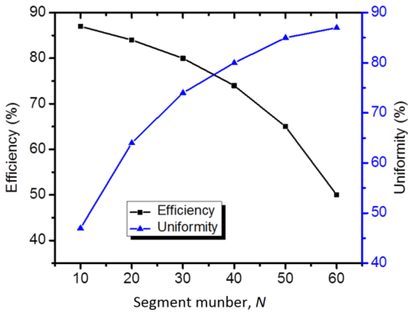
The uniformity equation (the following equation uniformity, Equation (4)) is utilized to calculate the uniformity U of the light on the receiver. Figure 10 shows the dependence of U on the segment number N. The higher the number of segments (or the smaller the size of the segments), the higher the optical uniformity. This can be explained by the methodology of the Fresnel design. The collimated beam output from the collimator is divided into many pieces, and each piece is redistributed and spreads over the receiver. Clearly, a smaller segment size can provide higher uniformity in the receiver.
Optical efficiency, which is defined as the ratio of the luminous flux in the receiver to the total luminous flux of the light source, is also a function of segment number N. Figure 10 shows the dependence of optical efficiency η on N together with uniformity. Efficiency decreases when segment size decreases. Optical efficiency has two types of loss effects: Fresnel loss and geometrical loss of the segment. In this proposed system, the Fresnel losses occur on the surface of the plano-convex lenses and linear Fresnel lenses. Another loss is the geometrical loss of the Fresnel lens. In an ideal case, no geometrical loss occurs when a perfect collimated beam reaches the Fresnel lens. However, our designed collimator based on plano-convex lenses provides a beam with a divergence of 7.5°. As a larger segment has a higher acceptance angle than a smaller one, the geometrical loss is smaller. Figure 10 shows a trade-off between optical efficiency and uniformity. For different specific purposes, the parameters of the Fresnel lens should be designed appropriately.
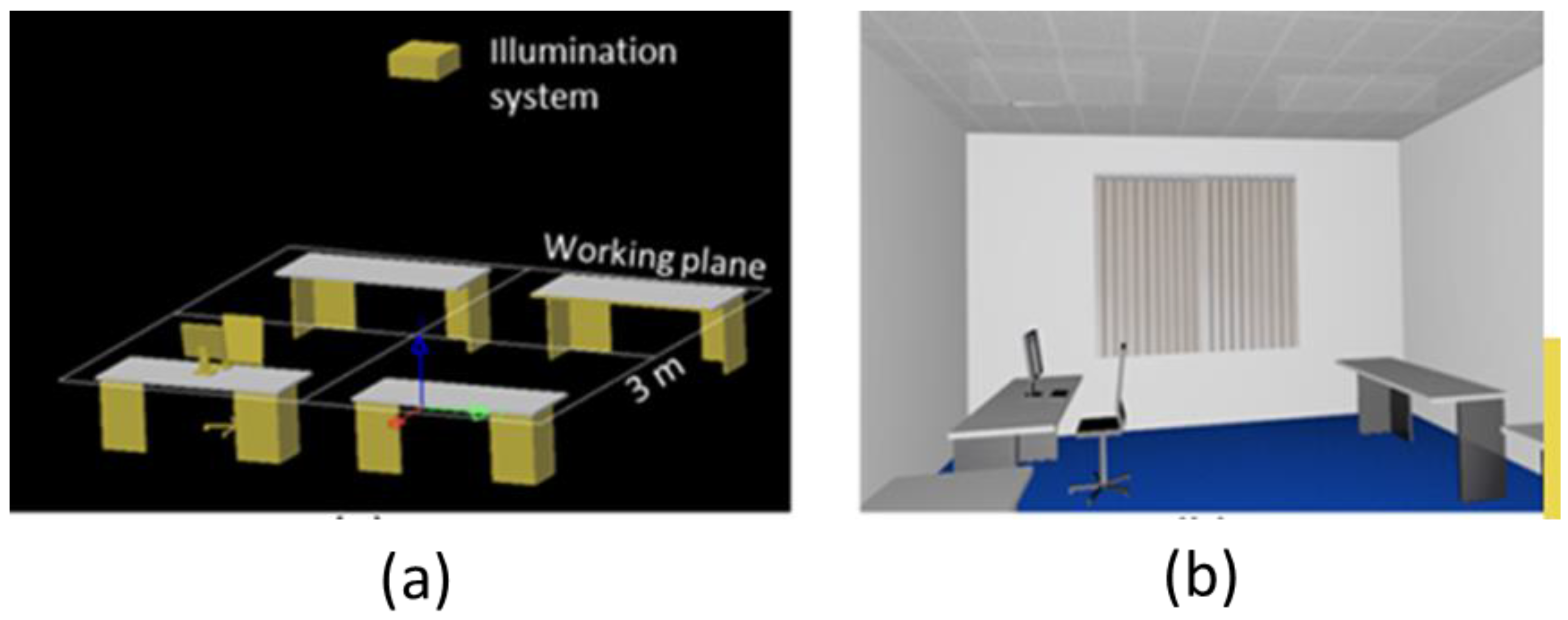
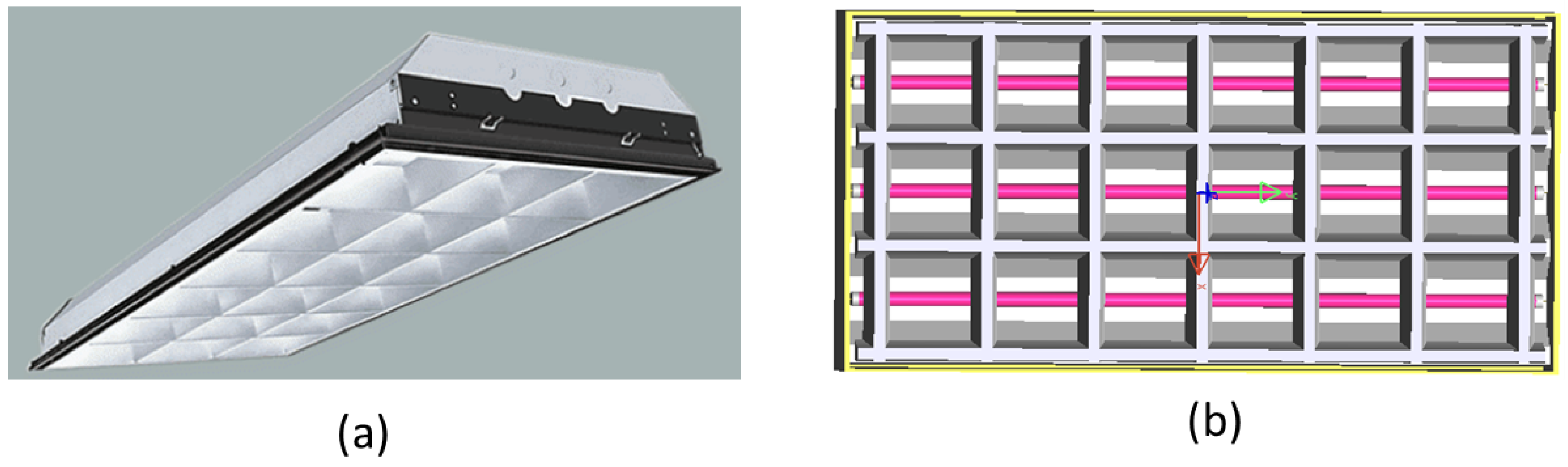
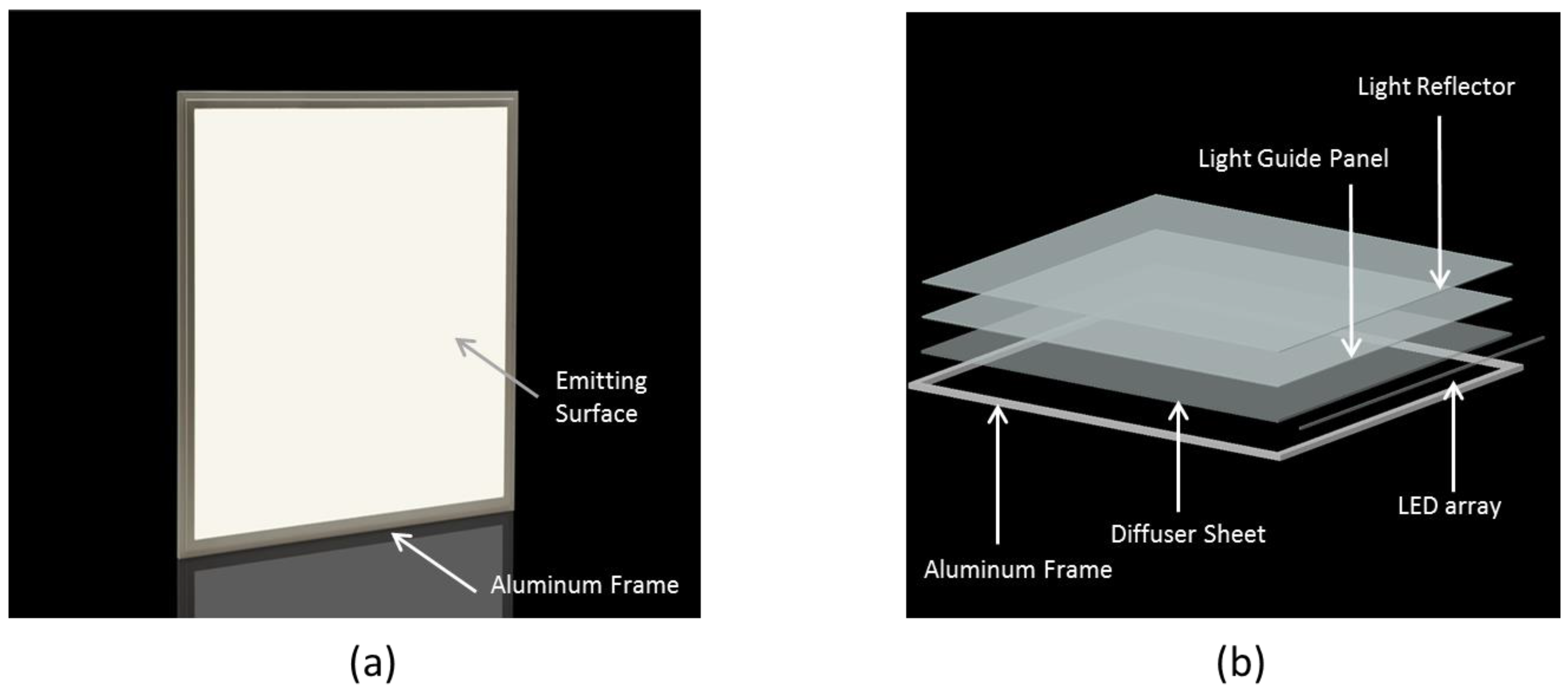
To evaluate the advantages of our proposed lighting system, the applications for indoor lighting and street lighting are simulated, and the performances of the systems are compared with those of traditional fluorescent lamps and LED panel ceiling light. For a typical office building, the minimum illuminance required is about 500 lux, and the requirement for uniformity is 60% [15]. In this study, we perform a simulation to evaluate the performance of the designed LED lighting system in a virtual room. The size of the room is 3 m × 3 m, and the interior is designed using LightToolsTM. The distance from the ceiling to the working plane (illumination target) is 2.7 m. The 3D view of the room’s interior is illustrated in Figure 11a,b. The Fresnel lens parameters are calculated according to these conditions. As shown in Figure 10, we select the Fresnel lens segment number of 30. Uniformity is achieved at 76.9% and optical efficiency at 82%. Other simulations using the traditional fluorescent lamp and the LED panel ceiling light for interior lighting were also performed for comparison. A typical fluorescent light fixture consist of a fluorescent tube and louver as shown in Figure 12a. In our simulation, a compact fluorescent lamp (fabricated of V-shape reflector, steel material and three fluorescent tubes) was taken into consideration. Figure 12b is a fluorescent lamp model built in LightTools. Recently, the LED panel ceiling light has been an innovative lighting product which can directly replace the conventional fluorescent lamps or light bulbs. We built a simulation model of a commercial LED flat panel light based on some parameters of the LED panel light model TLP-XX-6060 from SGSlight company (Shenzhen, China) [16]. Figure 13a,b is an LED panel light and the dissection of its components.
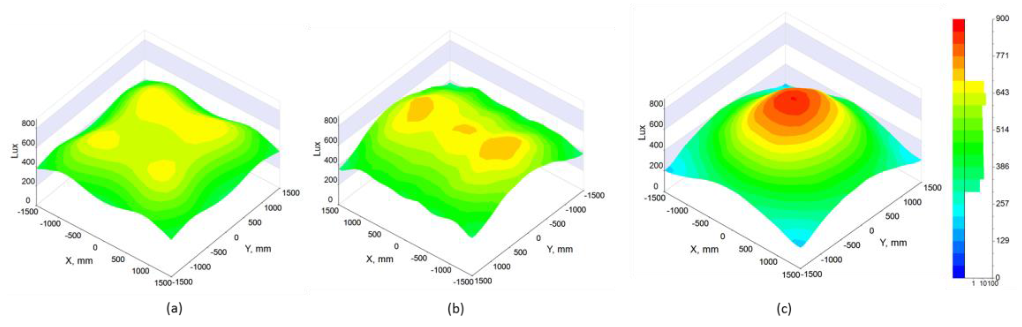
Figure 14a–c shows the light distribution on the working plane by using our proposed method, the fluorescent lamp and the LED panel light. Table 2 shows the comparison of the optical performances between three types of lighting methods. Using LED lighting for the building also overcomes inherent problems such as mercury pollution or the short lifetime of the fluorescent lamp. Although LED flat panels have been commercialized widely in recent years, current flat panel lights still have some big drawbacks. As shown in Figure 14c, an LED flat pane provided a narrow lighting area and a hot spot [17]. Simulation results also show that the uniformity of 39% is much lower than the standard requirement. In practice, the uniformity can be improved by increasing the number of LED panels; however, the material and installation costs also increase. Our proposed design can achieve higher lighting area and good uniformity. As shown in Table 2, the delivery efficiency, which is defined by the ratio of luminous flux on the working plane and the light source, is 76.9%, 24% and 45.5%, corresponding to our method, the fluorescent lamp and the LED panel, respectively. In our design method, all light output from the source is delivered and distributed uniformly to the illumination target directly so that the achieved delivery efficiencies can be very high in comparison to existing methods. Our proposed system requires only 60-W LEDs with 8000 lm to delivery 6150 lm to the working plane. The fluorescent lamps, which have a very large output angle, require 300 W of electrical consumption corresponding to 21,000 lm to illuminate the working area with illumination of 500 lux. Following the Table 2, only 5109 lm is delivered to the working plane by using fluorescent lamps with 21,000 lm, and the other part is delivered and absorbed by the room’s walls. An economic comparison is also shown in Table 2. Using our proposed design can save five-times the electric power consumption for illumination in comparison with using of traditional fluorescent lamps. The physical dimension of our design is much smaller than others, so this may contribute to the reduction of material and installation cost.
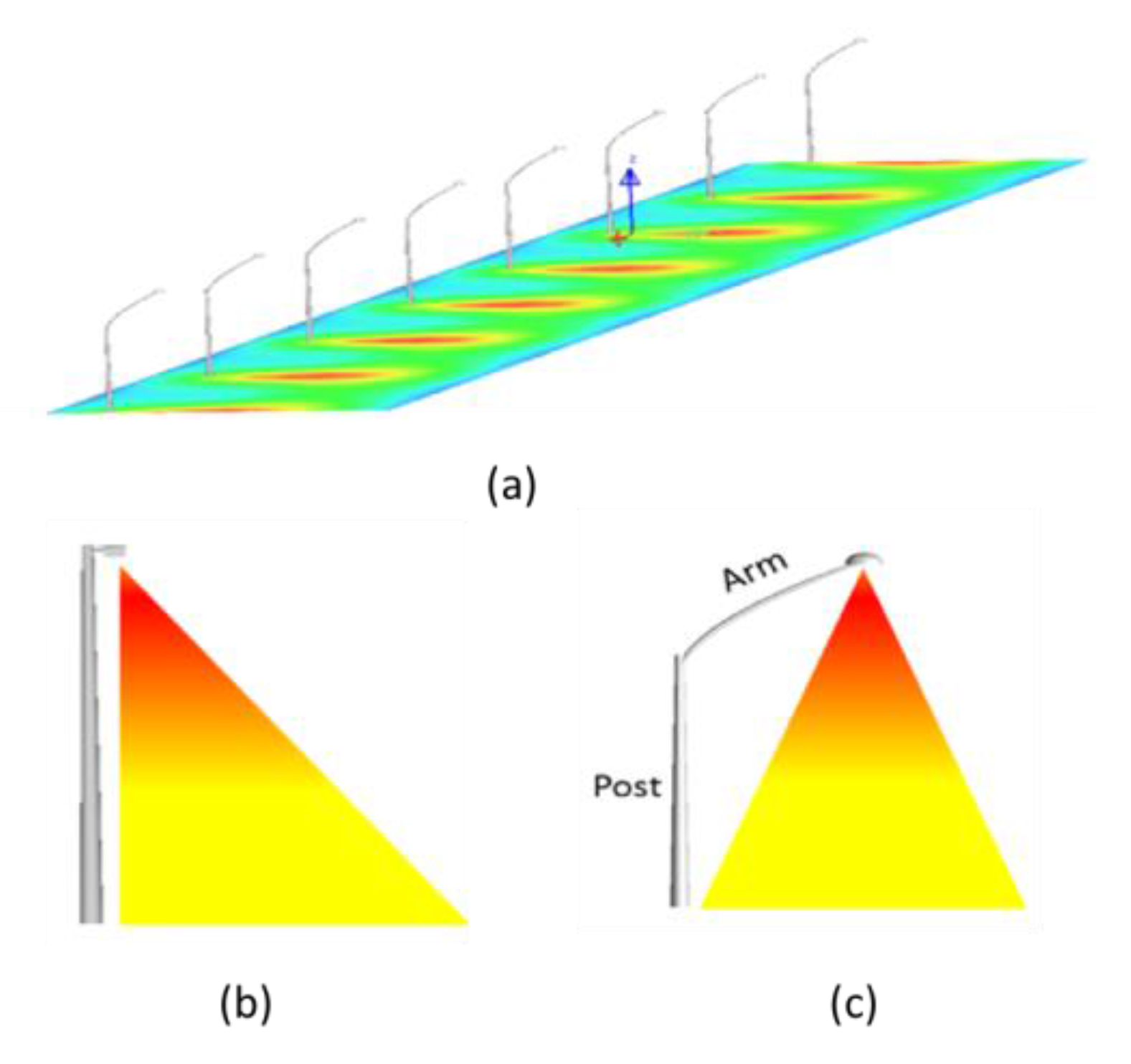
Optical solutions for conventional street lights rarely work well with LEDs. Many newcomers, and even some big players in the street lighting business, are having difficulties finding the best solutions to meet the relevant regulations. Getting the most out of streetlights is easy, but doing it uniformly is a challenge. We conduct simulations for street lighting using our proposed method and compare the performance of our system with that of typical LED street lamps. Figure 15a shows the visual image of a street light, and Figure 15c illustrates the structure of a conventional street lamp. Most lighting technologies work with the light source on a symmetrical axis, and thus, conventional street lamps use an arm to direct the light source to the center of the road. This arm makes the lamp structure bulky and hinders traffic. As mentioned above, our proposed lighting method can support off-symmetrical axis lighting, and thus, this arm can be eliminated, as shown in Figure 15b.
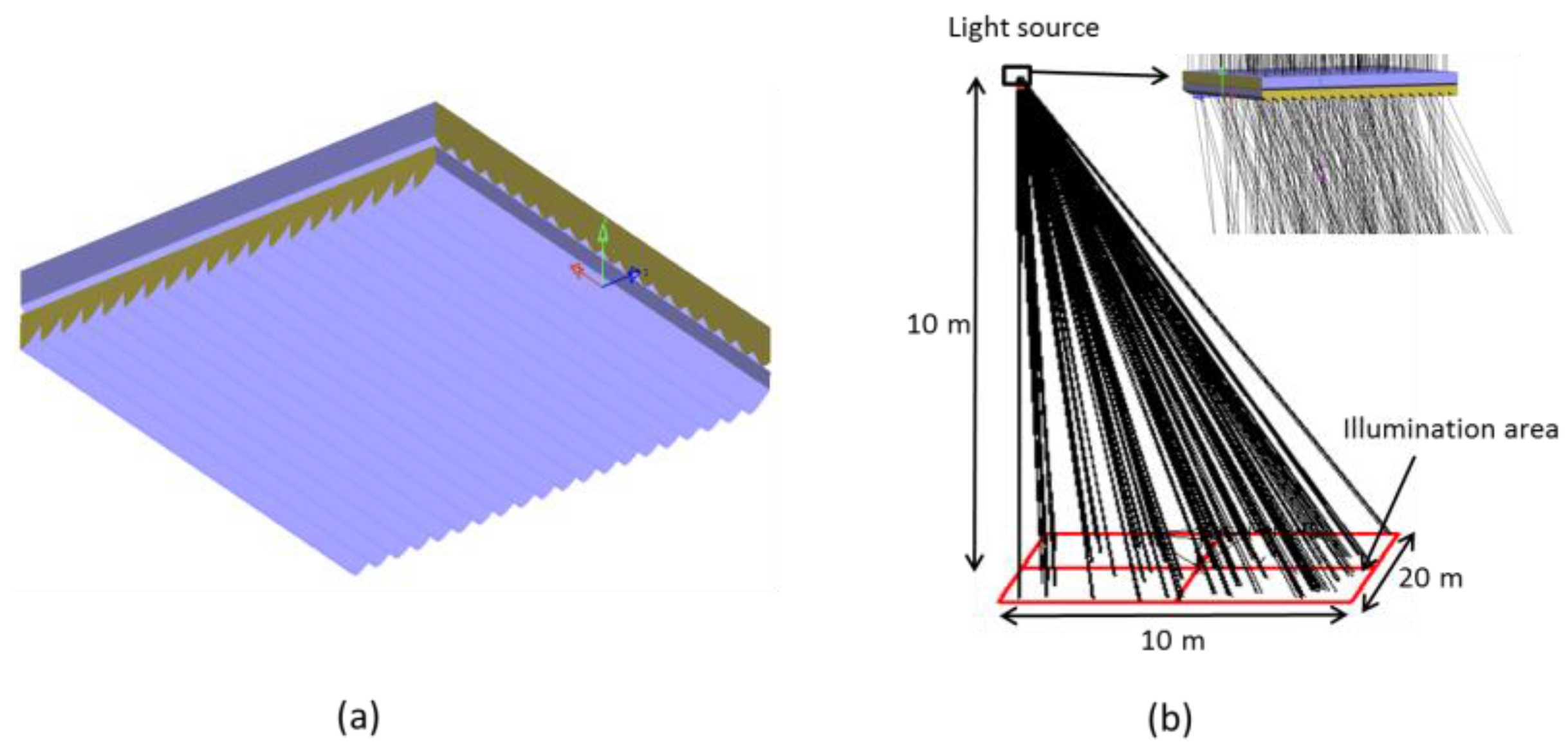
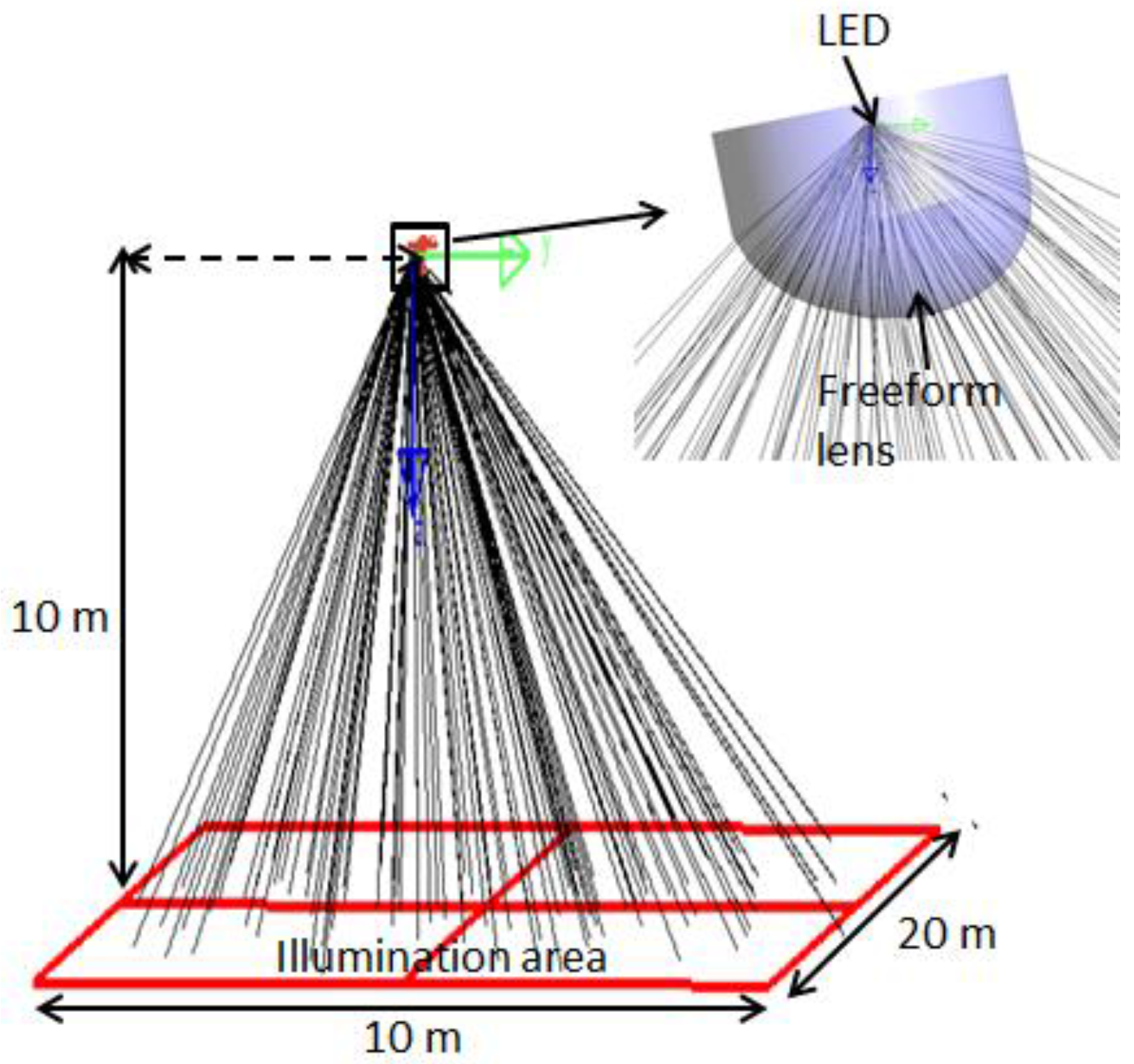
We carried out two simulations on our proposed design and a typical LED street lamp for comparison and evaluation. Assume that the distance from light source to the illumination surface is 10 m and the illumination area is a rectangular, 10 m × 20 m. The main goal was to illuminate a road surface area of 10 m × 20 m with a minimum illuminance of more than 20 lux, which is the standard requirement for regular vehicle traffic. Based on this initial condition, we calculated the structure of the linear Fresnel lenses as shown in Figure 16a. The upper Fresnel lens in Figure 16a was designed for on-axis illumination, and the lower Fresnel lens is for off-axis illumination. The ray tracing performance of one proposed street lamp module is shown in Figure 16b. For comparison, we conducted another simulation for a typical LED street lamp. We used the design of an LED street lamp using a freeform optics lens, which is available from the LightTools software library, as shown in the exaggeration of Figure 17. Figure 18a is the light distribution on the illumination area of our proposed design. The light distribution on the road surface which utilized typical LED street lamp is shown in Figure 18b.
As shown in Figure 18b, conventional LED street lights have a high-intensity area right under the lamp, and the intensity away from the center decreases rapidly, thereby decreasing one’s ability to observe light contrasts. Ideally, street lighting should be as uniform and as visually pleasing as daylight [18]. In our proposed system, the light was distributed uniformly on the road surface; therefore it could increase one’s ability of observation. Table 3 shows the comparison of the performances and energy savings between two types of street lamps. Our proposed design can save 50% of the energy consumption in comparison with using a typical LED street lamp.
The uniform distribution over a road surface using our proposed design can lead to a breakthrough in solutions for LED street lighting. In terms of mass production, the linear Fresnel lens structure can allow using the extrusion molding method, which is the least costly manufacturing process. The cost efficiency of the proposed LED lighting system can be realized because of the simplicity in material, shape, form, function, manner of operation, assembly and usage, which all present obvious capabilities for commercialization.
4. Conclusions
A uniform LED lighting system using nonimaging linear Fresnel lenses has been proposed and analyzed with the purpose of uniform illumination and energy savings. The design of the Fresnel lens based on the SMS method was discussed in detail. The designed system was modeled and simulated with LightTools software to explore the optical performance. The simulation results indicate that 82% optical efficiency was achieved at a uniformity of 76.9% for the proposed system. The simulation of the performance of our design for practical purposes, such as indoor and street lighting, and the comparison with a conventional light source were conducted. They show that our proposed design exhibits great potential for energy savings and commercialization.
Acknowledgments
This research was supported by the Basic Science Research Program through the National Research Foundation of Korea (NRF) funded by the Ministry of Education (2017R1D1A1B03031338) and the 2017 Research Fund of Myongji University.
Author Contributions
Ngoc Hai Vu conceived of and developed the original ideas. Ngoc Hai Vu carried out the performance analysis and simulations and wrote the paper. Thanh Tuan Pham supported the theoretical calculation process. Seoyong Shin supervised the research and finalized the paper.
Conflicts of Interest
The authors declare no conflict of interest.
Nomenclature and Symbology
| l | Lattice of LED array | mm |
| d0 | Distance from LED chip to collimator | mm |
| d1 | Thickness of collimator | mm |
| D | Diameter of the plano-convex lens | mm |
| n0 | Refractive index of the air | - |
| n1 | Refractive index of PMMA | - |
| αn | Incident angle to plano-surface of collimator | ° |
| βn | Refracted angle | ° |
| U | Uniformity | % |
| N | Number of grooves | - |
| η | Optical efficiency | % |
References
- Ding, Y.; Liu, X.; Zheng, Z.; Gu, P. Freeform LED lens for uniform illumination. Opt. Express 2008, 16, 12958–12966. [Google Scholar] [CrossRef] [PubMed]
- Su, Z.; Xue, D.; Ji, Z. Designing LED array for uniform illumination distribution by simulated annealing algorithm. Opt. Express 2012, 20, A843–A855. [Google Scholar] [CrossRef] [PubMed]
- Lumex. Is a High-Power LED the Best Choice for Your Application? 2017. Available online: http://www.lumex.com/is-a-high-power-led-the-best-choice-for-your-application (accessed on 23 August 2017).
- Shi, Y.; Li, B.; Zhao, M.; Zhou, Y.; Zhang, D. The design of LED rectangular uniform illumination lens system. Opt. Int. J. Light Electron Opt. 2017, 144, 251–256. [Google Scholar] [CrossRef]
- Gordon, J.M.; Rabl, A. Reflectors for uniform far-field irradiance: Fundamental limits and example of an axisymmetric solution. Appl. Opt. 1998, 37, 44–47. [Google Scholar] [CrossRef] [PubMed]
- Wang, G.; Wang, L.; Li, F.; Kong, D. Design of optical element combining fresnel lens with microlens array for uniform light-emitting diode lighting. J. Opt. Soc. Am. A 2012, 29, 1877–1884. [Google Scholar] [CrossRef] [PubMed]
- Kim, B.; Choi, M.; Kim, H.; Lim, J.; Kang, S. Elimination of flux loss by optimizing the groove angle in modified fresnel lens to increase illuminance uniformity, color uniformity and flux efficiency in LED illumination. Opt. Express 2009, 17, 17916–17927. [Google Scholar] [CrossRef] [PubMed]
- Moreno, I.; Tzonchev, R.I. Designing light-emitting diode arrays for uniform near-field irradiance. Appl. Opt. 2006, 45, 2265–2272. [Google Scholar] [CrossRef] [PubMed]
- Moreno, I.; Munoz, J.; Ivanov, R. Uniform illumination of distant targets using a spherical light-emitting diode array. Opt. Eng. 2007, 46, 1–8. [Google Scholar]
- Whang, A.J.W.; Chen, Y.Y.; Teng, Y.T. Designing uniform illumination systems by surface-tailored lens and configurations of LED arrays. IEEE/OSA J. Disp. Technol. 2009, 5, 94–103. [Google Scholar] [CrossRef]
- Qin, Z.; Wang, K.; Chen, F.; Luo, X.; Liu, S. Analysis of condition for uniform lighting generated by array of light emitting diodes with large view angle. Opt. Express 2010, 18, 17460–17476. [Google Scholar] [CrossRef] [PubMed]
- Wang, G.; Wang, L.; Li, F.; Zhang, G. Collimating lens for light-emitting-diode light source based on non-imaging optics. Appl. Opt. 2012, 51, 1654–1659. [Google Scholar] [CrossRef] [PubMed]
- IODA. N-Series Collimator Led Lens. Available online: http://ioda-it.com/product/collimators-led-light-lens/ (accessed on 1 November 2017).
- Miñano, J.C.; Benitez, P.; Liu, J.; Infante, J.; Chaves, J.; Wang, L. Applications of the SMS method to the design of compact optics. Proc. SPIE 2010, 7717. [Google Scholar] [CrossRef]
- Gary, S.; David, D.; Kevin, H.; Richard, M. Lighting Handbook, 4th ed.; Illumination Engineering Society: New York, NY, USA, 1966. [Google Scholar]
- SGSlight Lighting Solution. Available online: http://sgslight.com/products/led-panel/596x596/ (accessed on 27 October 2017).
- Wen, H.; Lin, L.B.-S. Improvement of illumination uniformity for LED flat panel light by using micro-secondary lens array. Opt. Express 2012, 20, A788–A798. [Google Scholar] [CrossRef] [PubMed]
- Laakkio, O. Winning the Optical Challenges in LED Street Lighting. Digi-Key Electronics. Available online: https://www.digikey.com.au/en/articles/techzone/2011/may/winning-the-optical-challenges-in-led-street-lighting (accessed on 23 August 2017).
Figure 1.
Physical layout of the uniform illumination system for a light-emitting diode (LED) array.
Figure 1.
Physical layout of the uniform illumination system for a light-emitting diode (LED) array.

Figure 2.
A rectangular array of LED chips was integrated into the printed circuit board (PCB) as a light source for the illumination system.
Figure 2.
A rectangular array of LED chips was integrated into the printed circuit board (PCB) as a light source for the illumination system.

Figure 3.
Design principle of the plano-convex lens based on freeform optics.

Figure 4.
Solid model of the plano-convex lens for LED collimation.

Figure 5.
An array of plano-convex lenses is placed on top of the LED array to collimate the LED light.
Figure 5.
An array of plano-convex lenses is placed on top of the LED array to collimate the LED light.

Figure 6.
(a) Design method for a segment of a linear Fresnel lens; (b) A single linear Fresnel lens redistributes light to a 1D receiver; (c) A light distributor including two linear Fresnel lenses can redistribute the light uniformly over a plane.
Figure 6.
(a) Design method for a segment of a linear Fresnel lens; (b) A single linear Fresnel lens redistributes light to a 1D receiver; (c) A light distributor including two linear Fresnel lenses can redistribute the light uniformly over a plane.

Figure 7.
(a) The light source is on the symmetrical axis of the illumination plane and (b) out of the illumination plane.
Figure 7.
(a) The light source is on the symmetrical axis of the illumination plane and (b) out of the illumination plane.

Figure 8.
Illustration of the simulation structure for efficiency analysis.

Figure 9.
Light distribution on a receiver with (a) N = 10; (b) N = 20 and (c) N = 30.

Figure 10.
Efficiency and uniformity depend on the number of segments N.

Figure 11.
(a) Simulation configuration for indoor lighting; (b) visual image of the test room.

Figure 12.
(a) A compact fluorescent lamp with a V-shaped louver and (b) a fluorescent light model built with LightTools software.
Figure 12.
(a) A compact fluorescent lamp with a V-shaped louver and (b) a fluorescent light model built with LightTools software.

Figure 13.
(a) Illustration of an LED panel light and (b) the dissection of its components.

Figure 14.
Light distribution on the working plane using: (a) our proposed lighting method; (b) fluorescent lamp; (c) commercial LED panel light.
Figure 14.
Light distribution on the working plane using: (a) our proposed lighting method; (b) fluorescent lamp; (c) commercial LED panel light.

Figure 15.
(a) Visual image of street lighting; (b) our proposed street lamp; (c) a conventional street lamp.
Figure 15.
(a) Visual image of street lighting; (b) our proposed street lamp; (c) a conventional street lamp.

Figure 16.
(a) The designed linear Fresnel lenses for street lighting purposes and (b) raytracing analysis of our proposed street lamp.
Figure 16.
(a) The designed linear Fresnel lenses for street lighting purposes and (b) raytracing analysis of our proposed street lamp.

Figure 17.
The structure of an LED street light based on freeform optics design and its raytracing analysis.
Figure 17.
The structure of an LED street light based on freeform optics design and its raytracing analysis.

Figure 18.
Light distribution of the street lamp on the road surface using: (a) our proposed design and (b) typical LED street lamp based on freeform optics.
Figure 18.
Light distribution of the street lamp on the road surface using: (a) our proposed design and (b) typical LED street lamp based on freeform optics.


Table 1.
Design parameters for the plano-convex lens.
| Design Parameters | Value |
|---|---|
| View angle of the LED (collection angle of the plano-convex lens) | 120° |
| Refractive index of the plano-convex lens (PMMA) | 1.49 |
| Distance of the source to the plano-convex lens, d0 | 0.5 mm |
| Thickness of the plano-convex lens, d1 | 10 mm |
| Diameter of the plano-convex lens, D | 10 mm |
Table 2.
Comparison of the performances between the three types of light source: our proposed LED source, fluorescent lamp and commercial LED panel light.
Table 2.
Comparison of the performances between the three types of light source: our proposed LED source, fluorescent lamp and commercial LED panel light.
| Comparison Categories | Proposed LED Lighting | Fluorescent Lamp | LED Panel Light |
|---|---|---|---|
| Initial conditions | |||
| Room dimensions (m) | 3 × 3 × 3 | 3 × 3 × 3 | 3 × 3 × 3 |
| Lamp dimensions (mm) | 100 × 100 × 20 | 610 × 400 × 1220 | 600 × 600 × 11 |
| Lumen efficacy (lm/W) | 130 | 70 | 130 |
| Luminous flux of light source (lm) | 8000 | 21,000 | 10,000 |
| Electric power | 60 | 300 | 77 |
| Optical performances | |||
| Luminous flux on working plane (lm) | 6150 | 5109 | 4547 |
| Illuminance Min/Max (lux) | 313/680 | 360/728 | 201/860 |
| Average illuminance | 514 | 568 | 506 |
| Uniformity (%) | 74 | 62 | 39 |
| Energy savings | |||
| Working hours (hours/day) | 10 | 10 | 10 |
| Working days (days/year) | 320 | 320 | 320 |
| kWh per year | 192 | 960 | 246.4 |
| Korean average cost per kWh ($/kWh) | 0.4 | 0.4 | 0.4 |
| Total cost for lighting per year ($) | 76.8 | 384 | 98.4 |
Table 3.
Comparison between our proposed LED street lamp and a typical LED street lamp.
| Comparison Categories | Proposed LED Street Lamp | Typical LED Street Lamp |
|---|---|---|
| Initial conditions | ||
| Height of post (m) | 10 | 10 |
| Illumination area (m) | 10 × 20 | 10 × 20 |
| Lumen efficacy (lm/W) | 130 | 130 |
| Luminous flux of light source (lm) | 12000 | 1800 |
| Electric power (W) | 92.3 | 140 |
| Optical performance | ||
| Illuminance Min/Max (lux) | 20/70 | 18/130 |
| Average illuminance | 45 | 70 |
| Uniformity (%) | 44 | 25.7 |
| Energy savings | ||
| Working hours (6 pm–6 am) | 12 | 12 |
| Working days | 365 | 365 |
| kWh per year | 404.3 | 613.2 |
| Korean average cost per kWh ($/kWh) | 0.4 | 0.4 |
| Total cost for lighting per year ($) | 161.7 | 245.3 |
© 2017 by the authors. Licensee MDPI, Basel, Switzerland. This article is an open access article distributed under the terms and conditions of the Creative Commons Attribution (CC BY) license (http://creativecommons.org/licenses/by/4.0/).
Share and Cite
MDPI and ACS Style
Vu, N.H.; Pham, T.T.; Shin, S. LED Uniform Illumination Using Double Linear Fresnel Lenses for Energy Saving. Energies 2017, 10, 2091. https://doi.org/10.3390/en10122091
AMA Style
Vu NH, Pham TT, Shin S. LED Uniform Illumination Using Double Linear Fresnel Lenses for Energy Saving. Energies. 2017; 10(12):2091. https://doi.org/10.3390/en10122091
Chicago/Turabian StyleVu, Ngoc Hai, Thanh Tuan Pham, and Seoyong Shin. 2017. "LED Uniform Illumination Using Double Linear Fresnel Lenses for Energy Saving" Energies 10, no. 12: 2091. https://doi.org/10.3390/en10122091
Note that from the first issue of 2016, this journal uses article numbers instead of page numbers. See further details here.