Review

Lithium-Ion Battery Storage for the Grid—A Review of Stationary Battery Storage System Design Tailored for Applications in Modern Power Grids

Department of Electrical and Computer Engineering, Technical University of Munich (TUM), 80333 Munich, Germany
*
Author to whom correspondence should be addressed.
These authors contributed equally to this work.
Energies 2017, 10(12), 2107; https://doi.org/10.3390/en10122107
Submission received: 18 November 2017 / Revised: 28 November 2017 / Accepted: 1 December 2017 / Published: 11 December 2017
(This article belongs to the Section D: Energy Storage and Application)

Abstract

:
Battery energy storage systems have gained increasing interest for serving grid support in various application tasks. In particular, systems based on lithium-ion batteries have evolved rapidly with a wide range of cell technologies and system architectures available on the market. On the application side, different tasks for storage deployment demand distinct properties of the storage system. This review aims to serve as a guideline for best choice of battery technology, system design and operation for lithium-ion based storage systems to match a specific system application. Starting with an overview to lithium-ion battery technologies and their characteristics with respect to performance and aging, the storage system design is analyzed in detail based on an evaluation of real-world projects. Typical storage system applications are grouped and classified with respect to the challenges posed to the battery system. Publicly available modeling tools for technical and economic analysis are presented. A brief analysis of optimization approaches aims to point out challenges and potential solution techniques for system sizing, positioning and dispatch operation. For all areas reviewed herein, expected improvements and possible future developments are highlighted. In order to extract the full potential of stationary battery storage systems and to enable increased profitability of systems, future research should aim to a holistic system level approach combining not only performance tuning on a battery cell level and careful analysis of the application requirements, but also consider a proper selection of storage sub-components as well as an optimized system operation strategy.

1. Introduction

In academia, it is common sense, that an intensified deployment of Renewable Energy Sources (RES) is the most promising strategy to pave a way towards a highly desired more sustainable electricity supply [1]. The analysis of recent developments clearly shows an ongoing success of increasing RES penetration and allows a projection towards RES having a crucial role of energy supply in a future sustainable energy system [2]. With higher shares of Photovoltaic (PV) and wind-turbine electric generators installed in modern power grids, the task of balancing electricity demand and power supply over time for all demand points connected to the grid becomes increasingly challenging [3]. It is necessary to match distributed and intermittent power generation with load demand for all times within the entire grid. While measures taken in power grid expansion and flexible demand allow for improved relocation and balancing of electricity flows, Energy Storage Systems (ESS) are capable to effectively equalize fluctuations and can compensate a mismatch of power generation and consumption via a coordinated power supply and energy time-shift.
Comprehensive overview to the manifold ESS technologies and their suitability to grid relieving applications have been given in various contributions [4,5,6,7]. Therein individual strength and drawbacks among the competing technologies are highlighted and it has been shown that their suitability might vary strongly with the proposed field of application. An approach to quantitatively compare various different storage technologies with respect to efficiency, power and energy density, response time, maturity and other performance indicators are presented, e.g., in [6,8]. Overview to presently installed ESS capacities and potential future developments is given elsewhere in more detail [9]. In brief, global storage capacity amounts to approximately 4.67 TWh in 2017 and is predicted to rise to 11.89–15.72 TWh in 2030. Despite Battery Energy Storage System (BESS) hold only a minor share at present, total battery capacity in stationary applications is foreseen with exceptionally high growth rates in their reference case prediction, i.e., rise from a present 11 GWh (2017) to between 100 GWh and 167 GWh in 2030 [9]. A recent review by Weitzel et al. [10] underlines, that the number of publications in the field of BESS has strongly exceeded any other type of electrical energy storage technology. This is attributed mainly to some strong advantages of BESS over other competing storage technologies including very fast response time, high efficiency, low self-discharge and feasibility of scaling due to a modular structure. While the authors describe the energy management and system optimization for various types of ESS in detail, the review does neither give insight to the design of BESS nor provide a guide to cost-benefit analysis for storage systems in stationary applications, which is the scope of this work.
Meanwhile, for BESS market growth and future cost prediction analyses have been conducted for both Electric Vehicles (EV) [11] and stationary system integration [12] showing a similar overall trend of significant cost decline attributed mostly to increase of battery cell production capacity. Interestingly, an experience curve analysis reveals the discrepancy of cost reductions observed in the past and projected for the future at the battery cell and the full storage system level: An average annual cost decline of prominent 30% on the cell level but only 12% on the system level have been identified [12]. Furthermore, this work points to a dramatic uncertainty in resulting cost for Lithium-Ion Battery (LIB) based storage systems: a vague range of 75–1130 US$/kWh has been derived from cost projections at a potential future production capacity of 1 TWh [12]. It can be concluded, that there is need for increased attention and further R&D on the storage system level to lower cost and improve the performance at the system level, where the application-specific value creation takes place.
All aforementioned high-quality contributions clearly contribute to the understanding of individual important aspects using batteries for stationary storage systems, e.g., the requirements for grid-connected BESS applications, storage system design, battery technology as well as energy management and operational control. However, there seems to be lack of a reviewing work providing a summary and a holistic overview to LIB based storage system design tailored specifically to stationary grid-connected applications. This work aims to bridge among the existent literature by providing a comparative analysis and may serve as a guideline to technology choice, system design concept and operation management for future LIB based stationary storage systems. It includes also a framework for profitability analysis and optimization of BESS with one or multiple applications and highlights directions for future research.
Figure 1 gives a schematic and formalized overview to the interface of a LIB storage system with the electric grid and highlights components, keywords and aspects of major importance for the analysis and discussion of this review: In brief, a LIB storage system typically includes the battery itself (battery cells assembled to modules and optional pack configurations), a thermal concept or Thermal Management System (TMS) (which may be subdivided to Battery-TMS (B-TMS) and System-TMS (S-TMS)), as well as an Energy Management System (EMS) control. Depending on the application of choice, the power electronics system may consist of single or multiple voltage inverter units (DC/AC link) and potentially a transformer coupling element for integration to higher grid voltage levels. The application side determines attainable profit (alternatively also value generation via increased reliability or savings due to a reduction of the customer’s electricity bill) via integration of the storage system and affects strongly the prerequisites for placement and operation of the storage unit. Appropriate sizing of the storage system (battery and power electronics) is a further criterion for system optimization, as for revenue maximization not only profits attainable but also the upfront cost for investments and potential replacement costs have to be taken into account.
Equation (1) provides a possible approach to a simplified cost-benefit analysis: It summarizes the major contributions necessary for a Return on Investment (ROI) analysis as has been proposed for the economic analysis of residential storage systems [13,14]. Other recent work underlines that cost-benefit analyses based on Levelized Cost of Electricity (LCOE) used effectively e.g., for the economic assessment of RES generation is subject to strong variation when applied to BESS assessment and depends e.g., on the application choice [15,16,17]. As such ROI analysis is preferred to LCOE for valuation and direct comparison of storage systems. Furthermore, for the shake of simplicity we limit the discussion to a net present value cost, annualized cost models are described elsewhere [16]. To estimate a project ROI, on the cost side all relevant factors of a Total Cost of Ownership (TCO) analysis have to be taken into account: One may differentiate among investment ( C i n v ) and operational cost ( C O P E X ) but should consider also depreciation periods or salvage cost to account for a technology lifetime [18]. Based on this approach, for the battery systems reviewed herein, an explicit reference to degradation related replacement cost ( C d e g r a d e ) is introduced accounting for material fatigue and degradation related cost. The economic benefit of storage integration P A P L may emerge from direct profit generation (e.g., arbitrage energy trade), cost savings (e.g., reduced electricity tariff) or value generation via improved reliability (e.g., via Uninterruptible Power Supply (UPS) functionality) [16]. For ROI analysis the annualized profit ( P A P L ) and cost flow ( C O P E X and C d e g r a d e ) may be lumped to overall project return ( A r e t u r n ). Individual contributions to the economic parameters introduced will be referred to in the subsequent technically oriented discussion.
R O I = A r e t u r n C i n v C i n v = ( P A P L C O P E X C d e g r a d e ) C i n v C i n v
Some technically oriented cost-factor contributions are summarized in Table 1. Several other factors to be considered on the cost side (e.g., real estate, insurance, interest rate, grid fees, maintenance, taxes and warranty contracts) are to be noted also, but will not be further discussed in this review.
The remainder of the paper is structured as follows: Section 2 summarizes important aspects on the performance and degradation behavior of LIB cells suitable for stationary applications. While Section 3 gives an overview to possible design of LIB based stationary storage, Section 4 classifies and distinguishes among prominent applications for BESS grid integration. The subsequent Section 5 presents modeling tools and analyzes system optimization for LIB based storage systems based on the aforementioned aspects. Section 6 summarizes the main findings and gives an outlook to future developments.

2. Lithium-Ion Battery Technology—Performance and Aging

Analyzing the LIB cell as core component of the battery storage system is essential for understanding the electrical and thermal characteristics as well as the degradation behavior of the entire storage system.
As in this review a detailed overview of battery materials is not the scope, we limit ourselves to describing three state-of-art technologies frequently employed for stationary storage systems based on a Carbon-Graphite (C) anode with Metal-Oxide (MOX)-type cathode: Nickel-Cobalt-Aluminum-Oxide (NCA), Nickel-Manganese-Cobalt (NMC) and Lithium-Iron-Phosphate (LFP). In the subsequent outlook a promising candidate for future systems (Lithium-Titanate-Oxide (LTO) anode with metal-oxide cathode) is briefly discussed. A more comprehensive and detailed overview to the wide class of materials used for battery storage can be found elsewhere [19,20,21]. Figure 2 provides a schematic cross-section view of the active components and function principle of a typical state-of-art LIB cell relying on the intercalation of Lithium-ions ( L i + ) with graphite anode and metal-oxide type cathode shuttled via an organic liquid electrolyte. Aluminum ( A l ) and copper ( C u ) serve as current collectors at the electrodes, respectively, as these materials exhibit desired stability and oxidation potentials [22]. As the interface of organic electrolytes with electrode materials is thermodynamically not stable, a Solid Electrolyte Interphase (SEI) is formed particularly on the Graphite anode side mainly during the first charge-discharge cycles. This Solid Electrolyte Interphase (SEI) layer protects the anode from a direct electrolyte exposure as it is electronically not conductive. However, as the SEI is not an ideal insulator it may grow slowly during further operation resulting in a loss of active Lithium. Battery capacity loss and increased resistance are often linked to this process [23].

2.1. Characteristics and Performance

Daniel et al. have described in detail materials suitable for lithium-ion intercalation systems and provided a link to several battery performance parameters relevant for LIB based stationary storage systems [19]. These include:
  • Safety and maturity on the battery cell level
  • Power capability and charge/discharge characteristics
  • Energy contents of the battery cell
  • Cycling efficiency and self-discharge
  • Material and battery cell cost
  • Degradation and aging phenomena
Variations of anode and cathode materials, their respective layer thickness, cell containment, as well as separator and electrolyte composition allow for tuning of specific aforementioned parameters but are typically at the cost of other performance indicators.
Various cell formats exist for state-of-art LIB cells, being cylindrical, prismatic and pouch format. Cell containment is of importance, as it may feature safety aspects and can also impact the thermal management and storage system assembly aspects discussed subsequently (cf. Section 3). More details on cell containment are discussed in [20].
While Table 2 provides a literature-based qualitative comparison of LIB performance parameters, Table 3 summarizes data-sheet derived parameters of some arbitrarily selected commercial cell representatives. Numbers found in literature and commercial cells data-sheets may differ quite significantly, which may be attributed not only to manifold possible variations of chemistry (active material composition, electrolyte, additives) and other influencing parameters (e.g., cell manufacture process, battery formation, and cell design) but also to non-standardized measurement procedures (e.g., different conditions for cycle life determination). For example, for all mature LIB cells under investigation manufacturers have shown commercial cells with a high cycle life over few 1.000 cycles and/or high charge/discharge capability. Quantitative numbers provided are directly linked to the commercial cell representatives depicted (cf. Table 3). All values provided in Table 3 serve only as an exemplary reference. The charge-discharge characteristics is commonly measured in terms of C-rate, i.e., a measure of current related to the nominal capacity of a cell. C-rate capabilities may vary strongly across battery cells and are often linked to cycle battery life. Along with several other cross-technology influencing aspects of LIB lifetime (e.g., cycle depth, temperature), this will be discussed in detail in the subsequent subsection. In general, to derive requirements on the battery cell level, it is necessary to analyze in detail the BESS application and system design/topology followed by the selection of a battery cell representative with a set of matching performance parameters. Other important parameters not listed in Table 3, e.g., Impedance/Resistance are often not provided in a battery cell data-sheet but need to be derived based on additional tests [24].
In contrast to automotive applications and LIB usage for consumer electronics, peak power performance and particularly gravimetric energy density are of subordinate importance for most stationary applications. In fact, material cost, energy contents, safety and cell degradation should be analyzed carefully and may differ significantly among different cells (cf. Table 3). Other potential factors to be considered are the energy need for material processing and battery cell manufacture as well as ecologic impact and compatibility to recycling, which is discussed in [21,35].
Due to an excellent trade-off between safety, lifetime expectation and energy density in combination with particularly competitive material cost, NMC:C battery cells are among today’s most employed battery chemistry for automotive and portable applications. A continued R&D effort facilitates improvements on specific energy (e.g., via implementation of over-lithiated cathode material) and/or battery degradation properties (via electrolyte additives) [36,37]. The commercial cell representative depicted in Table 3 provides an excellent trade-off between all performance parameters analyzed. The prismatic cell containment may integrate several safety features and allows straightforward assembly to module and pack level (cf. Section 3) [20].
Despite the upscale material cost of cobalt used as a constituent of NCA:C cells, the exceptionally high energy density attainable in commercial battery cells may lead to superior energy related specific cost on the cell level [38]. The technology offers one of the highest gravimetric energy densities with more than 250 Wh/kg realized in automotive grade cells, a fact that is key for implementation in both portable devices and electric vehicles [22]. In part, lower cost may also be attributed to an onset of production quantity induced scaling effects satisfying the demand of consumer electronics and automotive batteries. The almost two-fold higher volumetric energy density of the NCA:C cell representative shown in Table 3 in direct comparison to the aforementioned representative based on NMC:C technology, needs further attention. Differences in cell format for these cells (prismatic and cylindrical) make a direct comparison on the cell level ambiguous, as different system relevant features (e.g., safety and mechanical strength) may be included at the cell level. Furthermore, the NCA:C cell representative shows an extraordinary volumetric energy density at the cost of cycle life performance and may be suitable for most stationary applications only, when assembled in topologies with various cells connected in parallel. In fact, state-of-art system design concepts (cf. Section 3) have proven, that both cell representatives may be used for BESS with similar energy density and overall performance indications on the system level.
On the contrary, LFP:C batteries exhibit an overall lower cell voltage compared to the aforementioned technologies which result in an approximately 20% lower specific energy. As such, this chemistry is found less frequent in automotive applications, despite cells have been reported to show excellent safety and aging characteristics [39]. Furthermore, LFP:C battery cells show a hysteresis effect and an extremely flat Open Circuit Voltage (OCV) in an intermediate State of Charge (SOC) range (i.e., Δ V 100 mV for a SOC range of 10–90%), which is a great challenge for SOC determination, cell balancing and EMS control on the system level [40,41]. On the other hand, the very low voltage swing of LFP:C storage systems confined to intermediate SOC may allow cost effective and efficient power electronics inverter design. All the above mentioned factors have rendered this chemistry appealing for stationary applications (cf. Section 3). The commercial cell representative shown in Table 3 exhibits particularly high cycle life but falls short on volumetric energy density in direct comparison to the other mature cell representatives with carbon based anode reviewed.
Distinct anode materials, e.g., LTO and titanium niobium oxide have been successfully used for LIB cells in combination with various metal oxide cathode materials. The LTO:MOX based commercial cell shown in Table 3 shows extraordinary cycle life performance and rate capability. Nevertheless, to date, only few commercial LIB cells rely on non-carbon based anode materials, which may be attributed to lower obtainable cell voltage in conjunction with a metal oxide cathode and thus typically overall lower capacity. The intrinsic properties, aging behavior and potential future trends for anode materials, will be discussed in more detail in the following Subsections.
Not only the development of upfront investment cost for battery cells (strongly influenced by market development and scaling effects [12]) but also advancements performance parameters for LIB cells of different technology will strongly affect a future share of competing LIB technologies for stationary applications. Despite projections to future developments are subject to speculations, it is worth to analyze in more detail the aging of LIB cells in order to obtain an improved understanding of current developments and technical limitations.

2.2. Aging of Lithium-Ion Batteries

Aging is an unavoidable process caused by side reactions present in all electrochemical devices including battery cells. It may result in significant changes of capacity and resistance of a device over time and must, therefore, be considered in the system layout phase (e.g., necessity of over-sizing initial capacity) as well as in the system operation phase (e.g., adapting maximum allowed cell dispatch power). In fact, in contrast to lesser demanding applications in portable devices, a profitable usage of LIB in stationary applications requires a detailed understanding and ab-initio modeling of battery degradation: A long-lasting and demanding application will cause both performance and capacity reduction of the storage system and may significantly affect the overall business case via increased operational cost ( C O P E X ) and particularly high degradation induced replacement cost ( C d e g r a d e ). It is common to monitor a battery State of Health (SOH) to quantify the continued evolution of battery degradation resulting in both capacity fade and internal resistance increase (linked to decreasing peak power performance). Using Equation (2) the battery remaining capacity C m e a s 0 can be related to its nominal value ( C n o m 0 ) derived in new/used state under standard test conditions (denoted with superscript “0”). Due to transport regulations and application-specific minimum power requirements a replacement indicator S O H c a p r e p l a c e is defined. In automotive, often a S O H c a p r e p l a c e = 0.8 is applied, but for stationary applications and particularly in the context of second-life concepts lower values have been proposed [42].
S O H c a p ( t ) = C m e a s 0 / C n o m 0
Despite being studied for many years with continued effort, understanding and modeling the lifetime of LIB is a field of continued research [43,44]. Comprehensive overview and description of aging phenomena are provided in [23]. Various degradation mechanisms including electrolyte decomposition, passive film formation, particle cracking, and active material dissolution can be individually addressed on the material and battery cell level often leading to increased resistance, reduced capacity retention and/or an increased risk of an unsafe battery state [45,46].
Conventional analysis and modeling approaches are based on extensive battery tests [41,47,48] and derive empirical models often compatible with an Equivalent Circuit Model (ECM) approach for system performance determination. With an improved understanding of the cell-internal loss mechanisms, an increasing number of semi-empirical and physical models have been developed and successfully used for cell modeling [49,50]. Recently, non-empirical Physical-Chemical Models (PCM) have gained increasing interest [51,52,53]. Despite the usage of PCM models for aging prediction may allow giving a more detailed insight to cell internal loss mechanisms and how to circumvent these, it remains most challenging to find a valid parametrization of such models and to scale the cell internal models to the application relevant level of a full battery system [52,54,55].
With increasing capabilities of data logging and data management, data-driven approaches on the storage system level have also gained increasing interest recently [56]. Despite improved capabilities of these emerging approaches, it is still believed, that for simulations of the aging behavior of a full LIB storage system or an automotive battery pack high accuracy of a single battery cell model is essential [54,57]. The different approaches show individual strength and drawbacks, and Table 4 summarizes some indicators for comparison at a short glance.
For the remaining discussions of battery degradation, this work focuses on (semi-)empirical aging modeling and performance characterization via ECM as a state-of-art methodology for performance and aging prediction of LIB. In a modeling and application context is common to distinguish calendric and cyclic aging processes and analyze these separately [45,58]. As degradation processes often affect the quantity of Lithium-ions available for cycling in the cell, a simple superposition principle, i.e., an addition of capacity losses of individual contributions can be applied [59]. As a result, for simple modeling approaches the capacity fade due to aging processes may be estimated via Equation (3).
C t o t f a d e C c a l e n d r i c f a d e + C c y c l i c f a d e
In conjunction with a predefined replacement criterion, e.g., 80% remaining capacity as discussed earlier, battery replacement costs ( C d e g r a d e ) can be calculated (cf. Equation (2)).

2.2.1. Rest State—Calendric Aging Effects

matching well numbers found for LIB [59], a rule of thumb can be deComparative studies on aging effects with sensitivity to a variety of different cathode material compositions reveal the individual strengths and shortcomings of several competing cathode materials employed in LIB cells [60]. The rate of calendric aging is known to be influenced severely by the battery cell temperature. The Arrhenius law can be applied to model the thermally activated undesired side reactions in LIB cells which directly impact the calendric battery aging (cf. Equation (4)): Applying an activation energy of E a 50 kJ/( mol · K ) rived linking a 10 K increased battery core temperature to an approximate doubling of the calendric aging effect.
C c a l e n d r i c f a d e = k 0 , c a l · e E a / k T
The prefactor k 0 , c a l is strongly affected not only by the battery chemistry but also various additional parameters. e.g., recent studies include SOC dependent analysis of calendar capacity fade for various cathode materials [30]. The authors furthermore highlight the strong calendar aging impact of the graphite anode employed in most commercially available LIB cells.

2.2.2. Usage State—Cycle Aging Effects

Studying cycling induced aging effects of LIB reveals a complex relation of multiple superimposed and correlated effects: Cycle depth and SOC range are known to have a strong impact on the cycle aging of LIB batteries as these may induce active material dissolution or particle cracking [45]. Such mechanical stress induced effects were studied in detail e.g., on NMC:C cells [61]. Woehler-curve (also referred to as SN (stress number)) models have been previously applied to Lead(Pb)-Acid (PbA) batteries and take into account the cycle Depth of Discharge (DOD) [62]. Similar approaches have been proposed and adapted to LIB degradation kinetics [14,63]. Furthermore, an irreversible deposition of metallic Lithium (Lithium plating) is often observed for LIB cells with carbon-based anode materials, especially at low temperatures and high charge rates [64]. Others reported an increased battery aging under cycling condition prominent particularly at temperatures significantly above ambient conditions and high SOC, which may be attributed to SEI-layer growth, electrolyte decomposition and loss of available Lithium [45,65].
A cycle life analysis and model development specific to LFP:C batteries reveals the superior stability of the LFP cathode compared to other metal-oxide cathodes upon intercalation and de-intercalation of lithium-ions [66,67]. It has been confirmed for various cell compositions, that accelerated discharging and particularly charging of LIB may lead to enhanced capacity fade [68]. In order to confirm a model validity for applications with real operating conditions, static and dynamic validation experiments can be used as has been described in detail elsewhere [69].
Equation (5) summarizes functional dependencies of prominent influencing factors to battery capacity fade under load as briefly discussed herein. For explicit formulae and modeling approaches of cyclic aging, the reader may be referred to the aforementioned literature.
C c y c l i c f a d e f W o e h l e r ( D o D ) ; f L i p l a t i n g ( T , I ) ; f S E I g r o w t h ( T , S O C )
In summary, it is to be mentioned, that the influence factors for battery aging discussed herein depend strongly on the battery material composition and design. As such, it is task to analyze the suitability of a specific LIB cell to an application of choice. Furthermore, the thermal management of the battery system requires particular attention—best temperature for rest and operation conditions of the BESS may contradict to each other and the optimal system temperature may have to be specifically derived: To balance between the calendar and cycle aging effects discussed, being particularly prominent at high and low temperatures respectively, an approximation of a “comfort zone T o p t ” temperature range of T o p t 10 –30 °C has can be identified for exemplary stationary applications [65,70]. However, the ideal battery thermal conditions strongly depend on both cell technology and battery application chosen. In conclusion, energy management and system thermal management must be adapted to the cell-specific requirements in order to obtain best performance and lifetime as is also discussed in the subsequent Sections.

2.3. Future Developments

In order to reduce degradation effects associated with the graphite anode, other host materials for Lithium insertion have been under investigation. A well-explored candidate is Lithium-titanate-oxide employed e.g., in LFP:LTO battery cells. This “zero-strain” anode insertion material shows some superior properties including safety, reliability and cycle stability compared to graphite anodes [26,71]. However, due to the high potential towards L i / L i + and low specific capacity, the material combination with LFP cathode falls particularly short in specific capacity and thus cost per kilowatt hour. To date, the market share of LTO cathode based LIB is still low whilst automotive requirements push for increasing gravimetric energy density. Few commercial cells are available that use a combination of LTO cathode material with MOX composite anode materials exhibiting higher voltage [34]. Despite excellent cycle performance and high power capability the material combination falls short in energy and power density (cf. Table 3).
High Titanium ( T i ) raw material cost is another drawback of the anode material to be considered [19]. On the other hand, regarding battery aging LTO anode based LIB may show superior characteristics—the high equilibrium potential of > 1.5 V vs. L i / L i + suppresses the formation of a anode SEI-layer and thus reduces the effect of cyclable L i + loss over extended usage periods. At the same time, the high potential also largely reduces the risk of Lithium dendrite formation [22,39].
Other future post LIB technologies suitable for implementation in stationary systems include Lithium-Sulfur (LiS) as well as Sodium-ion (Na-ion) and Magnesium-ion (Mg-ion) batteries [72]. Despite showing strong potential for improvements in cost per kilowatt-hour, today’s laboratory research cells still suffer low cycling performance. The understanding of the underlying aging phenomena, modified storage system design and a well adapted system operation management will certainly be detrimental prerequisites to make use of the cost reduction potential of these new materials on the system level which is yet to be investigated further.

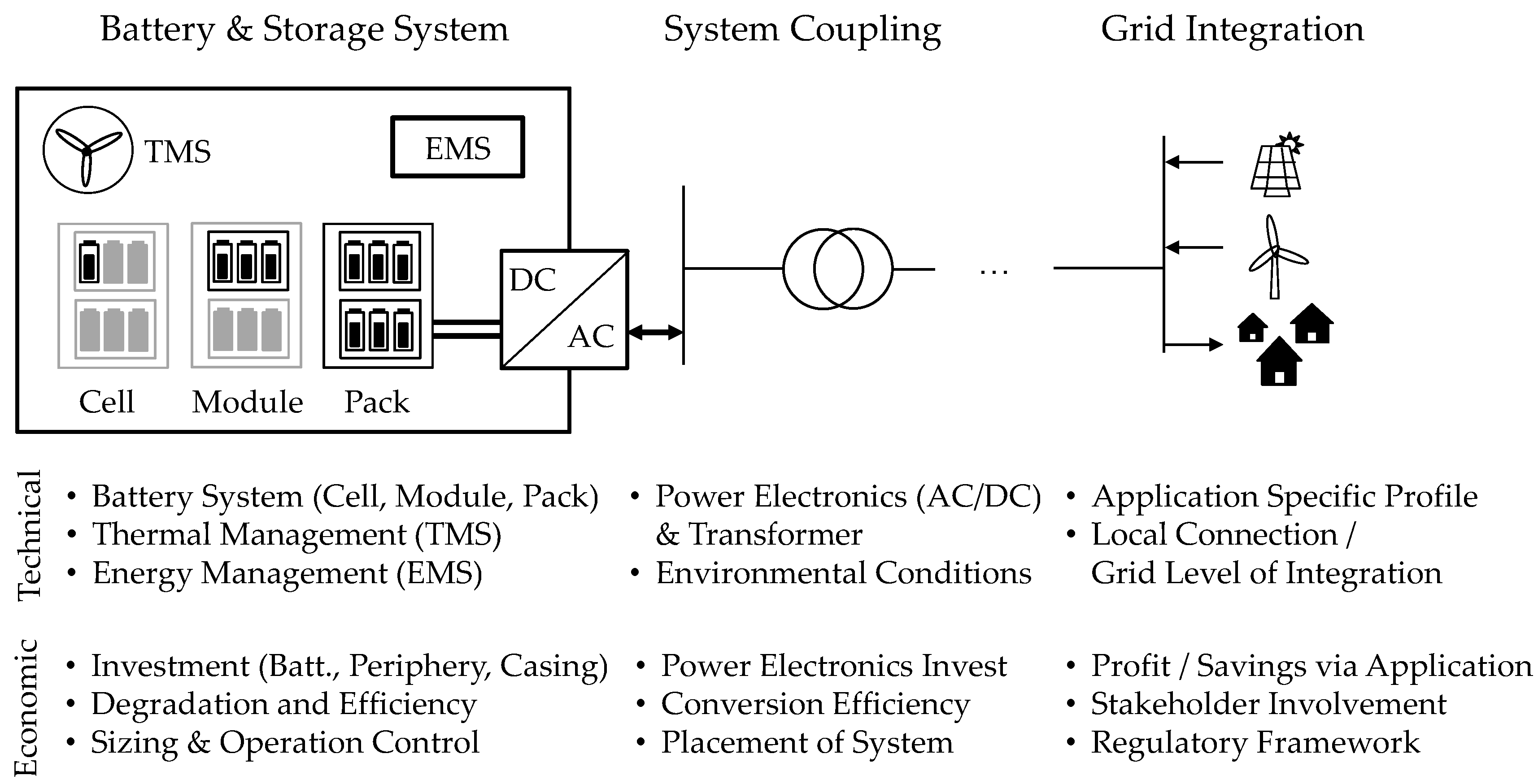
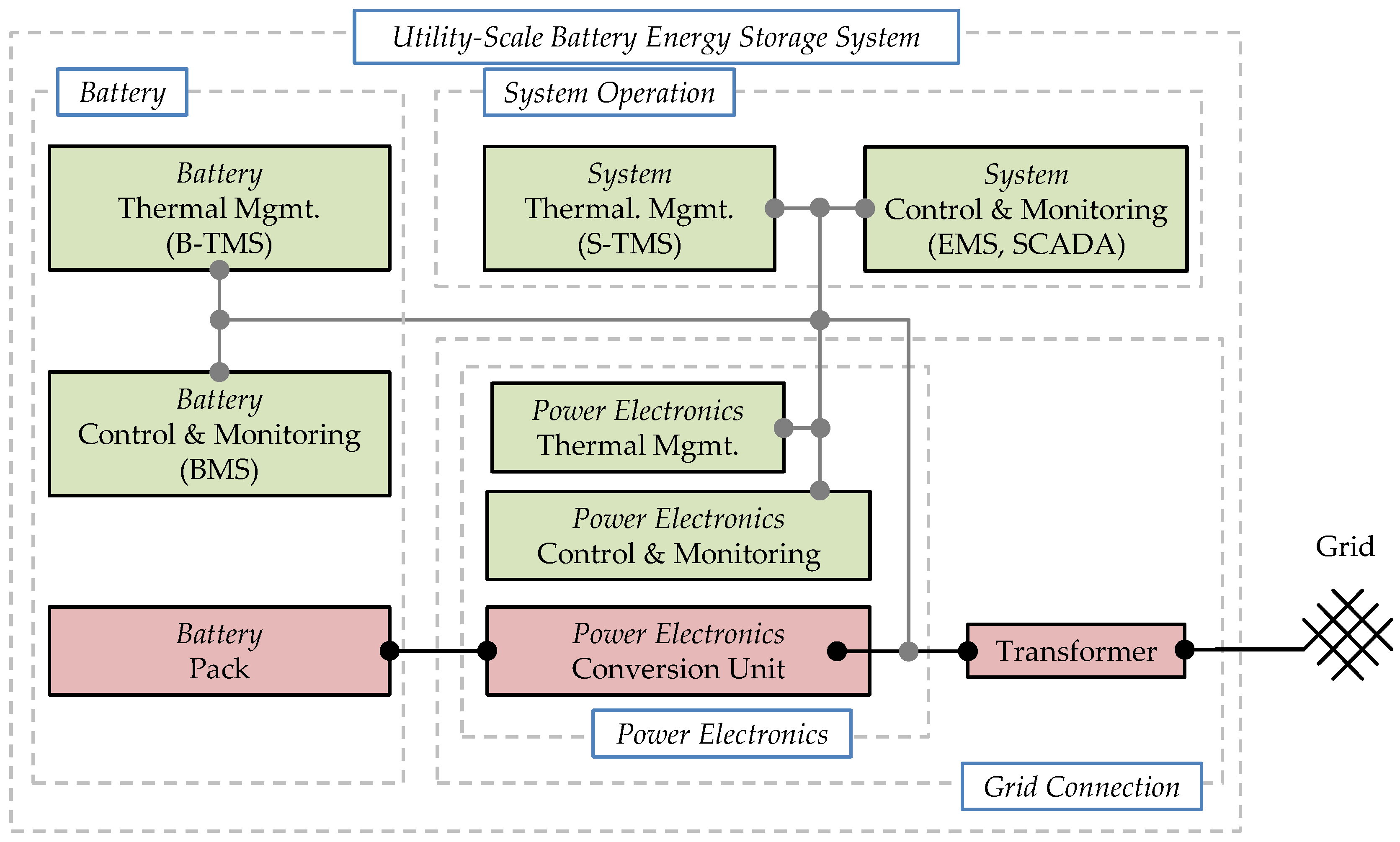
3. Stationary Battery Storage System Design

For usage of LIB in stationary storage applications several additional components and engineering efforts are necessary: after a brief discussion of cell interconnection and pack topology (Section 3.1), an overview to storage system components is given in Section 3.2. Special focus is put on the grid connection (strongly depending on the grid level to which the BESS is connected) and on power electronics topologies. A differentiation between utility-scale BESS and behind the meter Residential Photovoltaic Battery Storage System(PV-BESS) is made to account for deviations of the system connection. A second focus is put on the thermal management of the system due to its importance for the overall system performance and efficiency. Modeling approaches on the system level are described next in Section 3.3. Finally, some highlighted future developments in the field are discussed in Section 3.4.

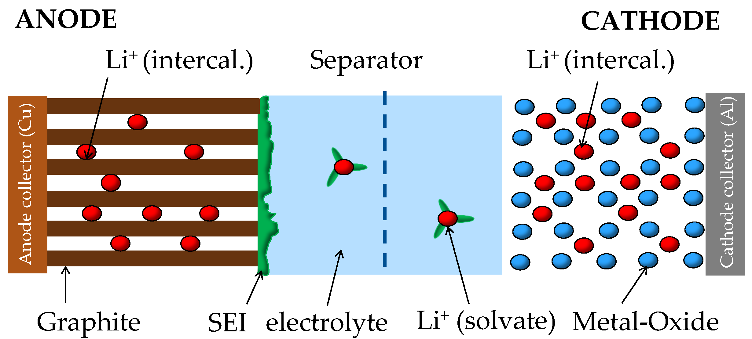
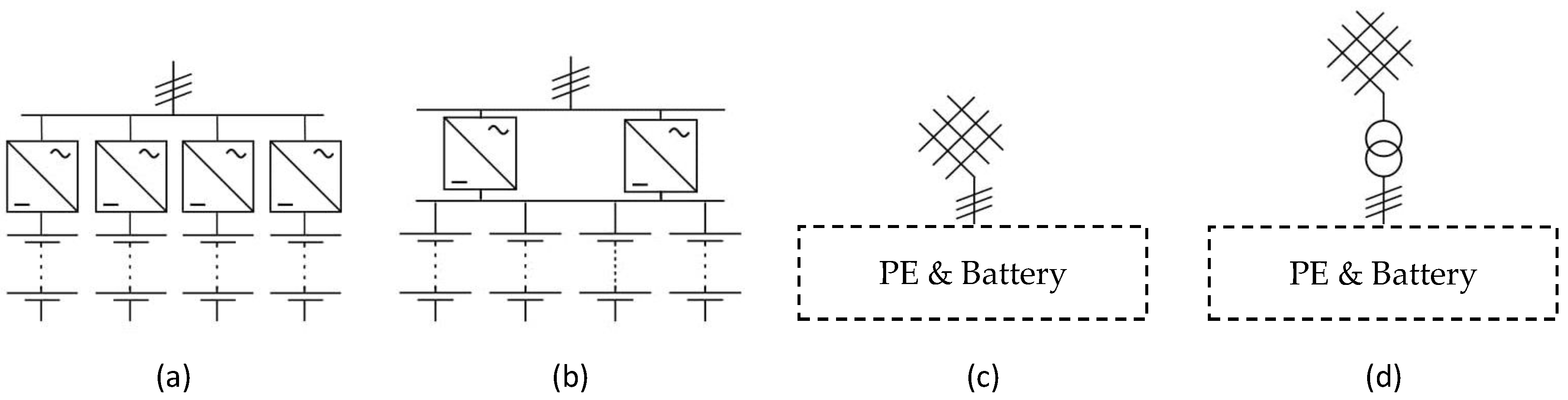
3.1. Cell Interconnection and System Topology

Interconnection of individual battery cells to battery modules and packs is a necessary step for developing stationary LIB based storage systems. While Serial connection of cells sums up the voltage of the individual batteries to the desired module or pack voltage, parallel connection of cells will increase the usable capacity. For details on design, control, and properties of serial-parallel connection in storage systems the reader is referred to other literature [73,74]. In brief, stationary BESS typically rely on groups of one to multiple parallel connected cells which are subsequently connected in series adding up to ≤60 V to form a battery module. Multiple modules may then be interconnected in serial-parallel configurations to achieve the desired capacity of the system, as well as the voltage required by the power electronics coupling as is discussed in the following section. Balancing of cell voltages is a challenge in serial connection topologies and requires a Battery Management System (BMS), which is discussed later as a specific component.

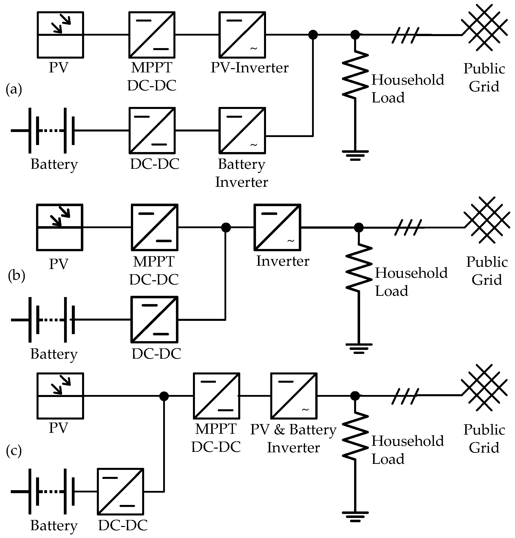
3.2. Storage System Overview
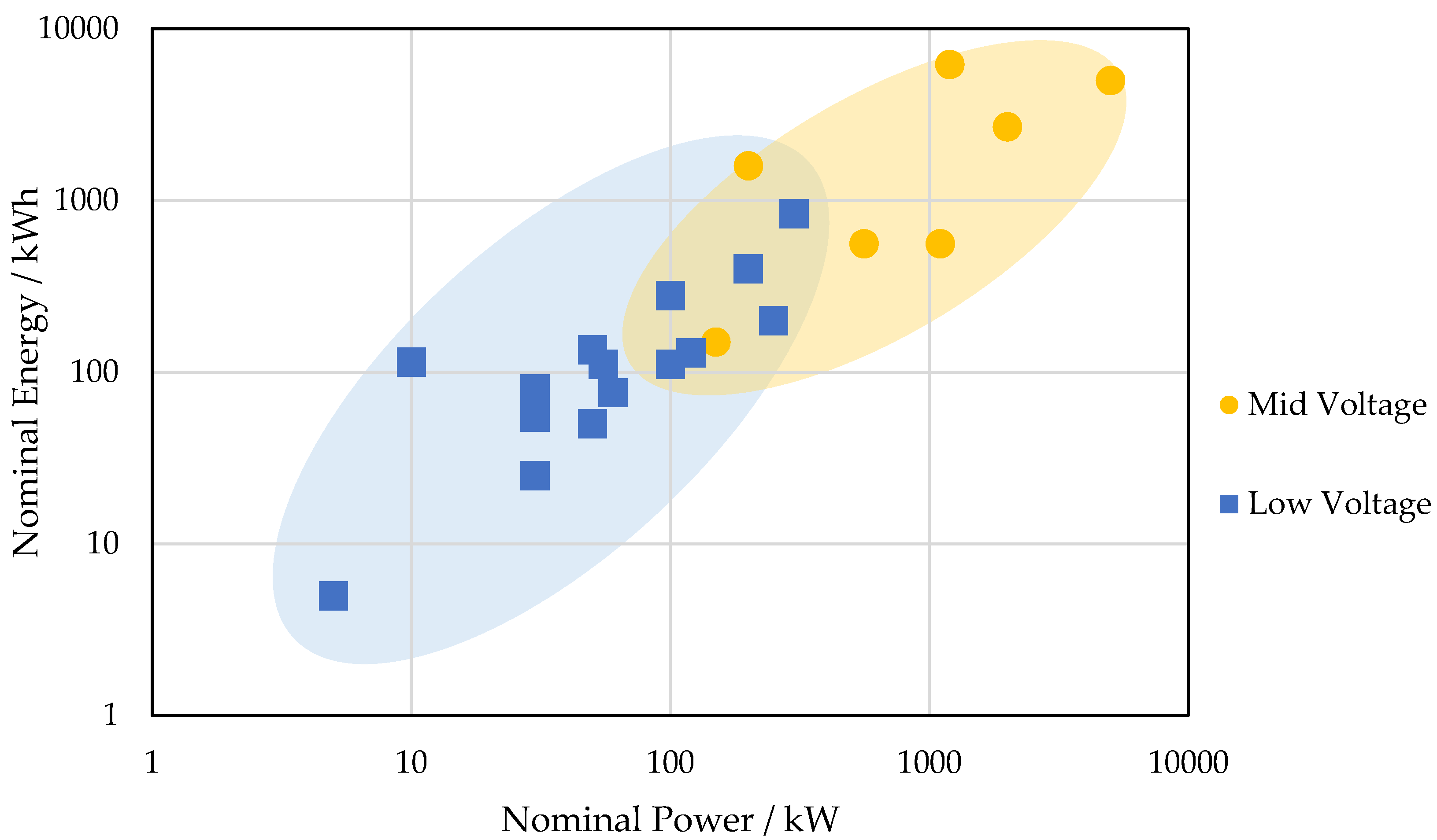
Figure 3 shows a schematic system setup of a utility-scale BESS. The system components are grouped by their function into Battery components, Grid connection components, and the components required for the reliable System Operation.
The system operation components are required for reliable operation of the overall system: System Control and Monitoring, is the general IT/monitoring, which is partly combined into the Supervisory Control and Data Acquisition (SCADA), of the overall system, but may also include fire protection or alarm units, and finally the Energy Management System (EMS), which is responsible for system power flow control/management/distribution. The System Thermal Management controls all functions related to the Heating/Ventilation/Air Conditioning of the system containment. The battery system consists of the Battery Pack, which connects multiple cells to appropriate voltage and capacity (cf. Section 3.1), the Battery Control and Monitoring, which is also often referred to as BMS. Key functions of the BMS are the protection the cells from harmful operation in terms of voltage, temperature and current to achieve reliable and safe operation, and the balancing of varying cell SOC within a serial connection [76]. For each cell information regarding functionality and actual energy and power capability is derived from BMS-estimated battery cell specific SOH and SOC values. Data is reported to the EMS of the BESS to control the power flow within the battery limits and enable execution of operational strategies. To date, most of the research in the field of BMS is aimed for automotive applications, however, various concepts and hardware design approaches can be transferred to stationary BESS [77].
The module/pack topology in terms of serial and parallel connection, which results in the voltage level as well as the the capacity (cf. Section 3.1), is a trade-off between multiple requirements. The power electronics topology/efficiency benefits in general from higher voltages for the connection to higher grid voltage levels. However, a serial connection with hundreds of cells features increased challenges in terms of reliability as a single cell fault can potentially deactivate the entire string [76].
The Battery Thermal Management (B-TMS) controls the temperature of the cells according their specifications in terms of absolute values and temperature gradients within the pack. Cell operation and aging are strongly affected by temperature, and thus temperature variations within the battery pack may lead to unbalanced current flow and increased aging [78]. As such, the B-TMS serves the functionality of the battery not only in terms of safety but also for enabling a long battery lifetime. In automotive applications, a variety of cooling methods are used, e.g., air cooling, liquid cooling, refrigerant cooling [79]. Phase-change materials have been under research for the application for automotive applications [80], as well as for stationary applications [81]. As the safety of LIB is today still a topic of ongoing research and development, several standards covering B-TMS exist today [79]. As with BMS, the research on B-TMS is mostly focused on automotive applications. Research methods can, however, be transferred to stationary applications. In contrast to automotive applications, utility-scale BESS feature additionally the system thermal management, which acts as a thermal barrier against direct impact of environmental conditions to the battery racks. For the smaller sized PV-BESS installations are typically confined to temperature-controlled rooms within a residential building. In fact, due to lower technical requirements B-TMS for stationary applications are typically less demanding and development-intensive compared to those employed for automotive applications: The majority of PV-BESS use passive air-cooling only [82]. The grid connection consists of the Power Electronics, connecting the Direct Current (DC)-voltage of the battery to the Alternating Current (AC)-voltage, and the transformer, which connects the system to the grid voltage level. The transformer is optional and can be omitted in case of matching voltage levels of both system output and grid connection. Section 3.2.1 discusses the relationship of the system and the required grid level in more detail.
The power electronics can be grouped in the Conversion Unit, which converts the power flow between grid and battery, and the required Control & Monitoring components, i.e., voltage sensing units, and the Thermal Management of the power electronics components, i.e., fan-cooling. Section 3.2.2 gives an overview to power electronics topologies used for utility-scale BESS as well as residential PV-BESS.

3.2.1. Grid Level

Transformers enable the connection of BESS to arbitrary, but typically higher grid levels [83]. As an example, the grid levels in the German-Austrian-Switzerland interconnected grid are: Extra-High-Voltage (XHV) in the transmission grid (220 kV AC or 380 kV AC), High-Voltage (HV) in the supra-regional distribution grid (36 to 150 kV AC), Medium-Voltage (MV) in the regional distribution grid (1 to 36 kV AC) and Low-Voltage (LV) in the local distribution grid (0.4 kV AC) [83,84]. A dedicated study of the energy efficiency of the grid connection of BESS in the LV/MV grid is presented elsewhere [83].
Behind-the-Meter (BTM) applications require a connection of the BESS at the grid level of the meter, which is typically the LV level for small consumers (e.g., residential, small industrial), and the MV level for large industrial consumers, which operate their own transformers [83]. The storage system integration of PV-BESS with variants of AC and DC linked power electronic topologies will be discussed separately (cf. Section 3.2.2). Similarly, applications for local grid support (cf. Section 4) specifically require the storage system at the grid level to be supported, typically again the LV and MV level [83]. Instead, utility-scale BESS providing grid ancillary services can feature system power in the Megawatt-range and thus require connection to the MV or potentially the HV level in the future [83]. An analysis of BESS applications and system connection to LV and MV grid levels revealed multiple storage application tasks confined to LV connection [85], but efficiency and cost-effectiveness of grid connection was not analyzed.
Figure 4 shows the grid level chosen for medium- to large scale industrial and utility-scale BESS according to their nominal energy and nominal power based on publicly available project data [86]. Data analysis reveals a turning point between low and medium voltage installations at approximately 200 kW, and a peak power connected to low voltage at 400 kW. Additional cost for a MV connection (i.e., transformer, and particularly medium voltage switch-gear) might be justified for larger project installations, as peak power constraints and system efficiency may become favorable with larger systems: Trade-off between cost for appropriately sized cable connections suitable for high power transmission at a lower voltage level and additional investment for transformers and switch-gear is highly sensitive to various parameters. Nevertheless, as a rule of thumb based on expert interviews, for 1 MW peak power, on the cost side a MV transformer installation and cable wiring may become competitive to an appropriate copper based LV cable at transmission lengths of below 100 m.

3.2.2. Power Electronics

Figure 5 gives an overview of variants of grid connection topologies for utility-scale BESS that typically consist of multiple battery packs and inverter units, which together add up to the total system energy and power. Power electronics units can be either installed dedicated to each battery pack (cf. Figure 5a) or the battery packs can be connected in parallel to a common DC-bus (cf. Figure 5b).
A grid connection example to the LV level is depicted in Figure 5c, whereas the connection to higher grid levels via a transformer is depicted in Figure 5d.
A clear advantage of the dedicated pack to inverter connection topology is that the power per battery pack can be individually controlled. Each unit is independent, which enables also handling in parallel multiple grid applications at a time whereby each string (inverter plus pack) still follows only a singular application request. Reliability can be also higher in this configuration, as failure of a single power electronics unit or a battery pack does not directly harm other unit’s operation. In systems with a common DC-bus, the power electronics units can be turned off at partial load to avoid high losses associated with numerous units in operation. The total current is (in theory) evenly distributed among equal battery packs. In practice, impedance variations due to temperature variations or aging and production imbalances may lead to unequal currents that cannot be directly controlled. As a result, for this topology the battery design must meet high technical requirements for a minimum of impedance variations, especially for LFP based cells due to the aforementioned flat OCV curve (cf. Section 2.1) [87]. As for the reliability, failure of a single pack in the parallel connection topology does not necessarily lead to loss of power immediately. A dedicated study of system efficiency in the aforementioned topologies with additional sensitivity to single-stage and two-stage topologies is presented elsewhere [83].
A large variety of power electronics configurations exist for inverter/rectifiers and DC-DC converters. Pires et al. [88] discussed the power electronics technologies suitable for BESS grid integration and divided them into standard, multilevel and multiport technologies. The simplest structure and standard technology is based on the two-level voltage source inverter. Multilevel and multiport technologies show potential advantages (e.g., higher efficiency at partial load, distributed thermal loss dissipation, lower required blocking voltage) but require a higher number of additional switching devices and complex control. Commercial scale realization for stationary BESS is yet to come.
Chatzinikolaou and Rogers [89] evaluated power electronics designs for a BESS connected to the 11 kV grid level through simulation. Three topologies were compared: (I) a low-voltage battery with single-stage three-phase bridge inverter and a step-up transformer; (II) an intelligent high-voltage battery featuring module level MOSFETs for balancing; combined with a high-voltage single-stage two-level converter interface without a transformer; and (III) a battery using a cascaded H-bridge multilevel converter.
Bragard et al. [90] presented and evaluated the grid integration for a 5 kW PV-BESS, as well as for a 100 MW MV system. Topology, efficiency, and cost are investigated and compared based on the exemplary systems connected to the LV and MV grid level. Results showed that although differences in cost and efficiency were identified for the systems themselves, a proper investigation has to include the local grid structure in terms of additional cost and transport losses for a holistic evaluation.
Considering commercial utility-scale power electronics for BESS, various components originally developed for motor drivers (e.g., Siemens Sinamics S120 [91]) and photovoltaic inverters (e.g., Bonfiglioli RPS [92]) may be utilized, as these applications feature similar conversion tasks. Nominal power ranges from less than 1 kW for PV-BESS to several 100 kW per unit for utility-scale BESS.
For PV-BESS, the power electronics topologies can differ from typical grid-connected BESS due to direct linkage options with the PV-system. Figure 6 shows three commonly employed power electronics topologies of residential photovoltaic BESS. Figure 6a shows a typical AC-coupled topology: A battery is connected via a DC/DC converter to the battery inverter/rectifier. The link between PV-inverter and the household load is established via the electrical power lines within the household. The topology can be easily retrofitted to an existing PV system and thus features a high flexibility.
A DC-bus-coupled system is shown in Figure 6b. Here, the battery DC/DC converter is connected to the high-voltage DC-bus between the Maximum Power Point Tracker (MPPT) DC/DC converter and the inverter to the grid. This enables higher efficiency for the power flow path from PV to BESS in comparison to the AC-coupled system, as no DC/AC conversion is required.
A DC-link option coupling the battery via the MPPT DC/DC converter is shown in Figure 6c. This topology is also known as generator-coupled topology. While this architecture may also allow for high conversion efficiency for the power flow from PV to the BESS, it requires a fast and precise communication link between the battery and the AC-grid link to satisfy the local demand via PV and/or battery at all times feasible. Both DC-coupled topologies usually cannot be retrofitted easily to existing PV systems, but may provide a more cost-effective solution for new combined PV-BESS installations as only one AC/DC converter is required. Quantitative and detailed comparisons of PV-BESS topologies analyzing the system’s efficiency and cost-effectiveness are yet to be conducted.

3.2.3. System Thermal Management System (S-TMS)

The thermal management on the system level (S-TMS) ensures safe and reliable operation conditions for all components within the system containment. Requirements for the S-TMS may differ significantly among storage projects: BESS may be installed in various regions worldwide with varying ambient temperature. Furthermore, the storage system containment and positioning offers additional degrees of freedom. The S-TMS is typically utilized year-round and can severely impact the energy consumption of the entire system if not matched well to the thermal requirements [93].
Most systems rely on baseline active air-conditioning to ensure a steadily controlled temperature. Additional ambient air cooling, triggered only if external temperature is appropriate, may reduce the overall power consumption and can improve the system’s energy efficiency. A thermal insulation and separation of power electronics and battery (i.e., a two-zone S-TMS setup) allows for dedicated temperature control and thus improved overall power consumption: Typically batteries are more temperature-sensitive, whereas power electronics components allow for higher operating temperature. As an example, the Energy Neighbor prototype battery system features a two-zone setup with the additional option of fresh air ventilation of both zones separately [94].
Neubauer et al. [95,96] analyzed the thermal behavior of BESS for different climate zones and showed that solar irradiation may cause an increased battery degradation in sun-trap locations if the storage system temperature is moderated appropriately through insufficient B-TMS and S-TMS. Gatta et al. [97,98] evaluated the power consumption of the S-TMS for BESS and showed that the auxiliary consumption through the S-TMS increases with higher system utilization. Rydh et al. [99,100] simulated LIB PV-BESS for the calculation of the overall system efficiency by including the auxiliary consumption of the S-TMS and analyzed the impact of different battery operating temperatures. Results showed a maximum efficiency of 80% for LIB based PV-BESS.

3.3. System Simulation

The system simulation of BESS requires modeling of the key components in a coupled approach and is highly sensitive to the storage application. In most contributions analyzed, not all components are included for simplification purposes or due to the unavailability of required data. e.g., Patsios et al. [54] evaluated a storage system simulation based on a single-particle cell model including calendar aging effects (cf. PCM modeling, Section 2.2) combined with discrete time power electronics models. They showed a trade-off for optimal SOC of the storage system: a higher SOC increases the battery degradation, whereas a lower SOC decreases the energy conversion efficiency.
Magnor et al. [101] simulated a PV-BESS with the battery through ECM and with a dynamic power electronics model, which included the controller dynamics to evaluate the transient control performance. They showed that neglecting the high-frequency currents from to the converter switching at high-frequency, leads to an underestimation of the effective current causing a significant model error.
The above-mentioned studies are only examples to the interplay of various components within the storage system and to the degrees of freedom in BESS simulations. In fact, present state-of-art BESS simulations and modeling tools available typically do not include all key components of the system under study. Instead, most studies focus on a specific system performance aspect, e.g., cell aging [54], power electronics losses [89], or economic evaluations [13,14]. Model approaches should be carefully selected in terms of the covered mechanisms and goals of the work. An overview to publicly available tools for BESS modeling is given in this review (cf. Section 5).

3.4. Future Developments

Power electronics topologies for BESS are still in rapid development. Today’s solutions are mostly based on existing technologies with little address for battery-specific challenges. Multilevel converter can address challenges of battery systems more specifically, such as low efficiency at partial load as well as SOC balancing [102] and the reliability of serial cell strings [103]. The trend for solar inverter to higher DC voltages from 600 V to 1200 V and today up to 1500 V is also a possibility for the BESS as significant cost reductions for the power electronics are possible.
Test protocols and system metrics are required to monitor and validate the performance of BESS in field applications. Such measures may also help to perform an assessment and subsequently improve the design of storage systems with respect to efficiency, battery aging, reliability, and cost. A set of initial protocols for measuring and calculation of system metrics has been proposed by Bray et al. [104]. Duty cycles for frequency control, a major BESS application are developed and made available for tests by Rosewater and Ferreira [105]. For deployed systems, a performance and health monitoring protocol based on regular reference performance tests as well as on the evaluation of the application performance has been proposed by Baggu et al. [75]. Driven by an emerging interest on PV-BESS, their system performance and efficiency has been analyzed in detail [106] and test protocols for standardized characterizations of system performance were proposed [107]. It is expected that the amount of available test protocols, validation methods, and performance indications will rapidly grow in the near future and become linked via a set of storage system modeling tools. These are seen as a framework and a prerequisite for rapid and innovative storage system design improvements.
Hand-in-hand with the increased penetration of LIB in the automotive sector, recycling, and battery re-usage concepts are discussed more frequently. Second-life usage of semi-depleted automotive batteries in less demanding stationary applications might become a promising concept for an extended battery exploitation and improved cost-to-use rates [108,109,110]. While economically viable options of battery re-usage have been identified, in line with literature the authors emphasize that challenges regarding battery SOH determination, safety-related aspects, and compatibility issues are yet to be overcome [111,112,113]. Others proposed the secondary use of off-the-shelf automotive battery concepts, i.e., integrating new battery packs originally designed for the automotive sector for stationary storage usage [114]. Despite overhead production cost (e.g., for automotive grade battery pack housing) and assembly challenges in stationary BESS, this concept might be an economically viable solution: as mentioned earlier, due to scaling effects automotive pack prices are often seen far lower than battery modules and racks originally designed for stationary usage [12]. In fact, recent pilot projects underline the interest of the industry to second life/second use concepts for mid-size demonstration and utility-scale commercial BESS as has been underlined by recent demonstration projects (e.g., BMW in cooperation with Bosch and Vattenfall in Hamburg, Germany [115], Daimler in cooperation with The Mobility House, GETEC and REMONDIS in Luenen, Germany [116]).
Furthermore, Vehicle-to-Grid (V2G) concepts which propose the electric vehicle integration and active support of the grid have been proposed and tested since long [117,118]. However, controlled charging and bidirectional charge/discharge of vehicles poses new challenges to battery aging stability and charging station hardware [119]. Constraints and challenges of this and other combined applications is discussed in the following Section.

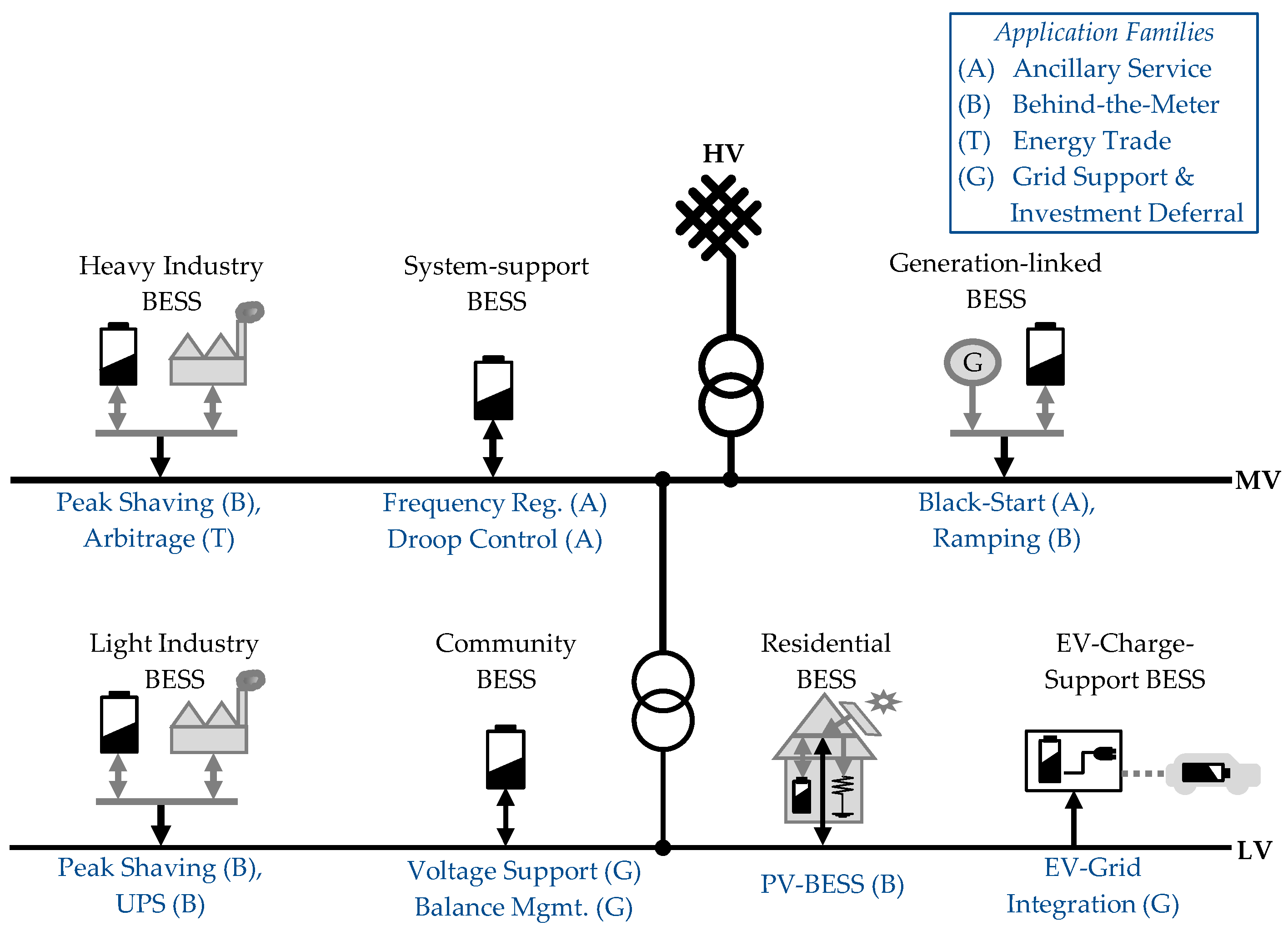
4. Grid-Applications for BESS

This Section describes a selection of applications frequently discussed for LIB based stationary storage systems. First, a classification of applications is introduced and discussed in context of value streams, stakeholders and impact to the grid. While Section 4.1 describes the different applications in more detail, Section 4.2 analyzes BESS integration and operation in three exemplary use cases and evaluates previously mentioned costs factors (cf. Section 1). On this basis, system design parameters (e.g., power-to-energy ratio) and constraints for storage operation are derived.
Following the approach of Palizban et al. [120], Figure 7 gives a schematic overview to BESS integration to distinct grid levels serving a series of application tasks in modern power grids. In contrast to their work, herein the focus is confined to LIB based storage systems, where most of today’s applications are found to reside in the LV and less frequently the MV grid level (cf. Section 3.2.1). In fact, use cases and grid integration of non-LIB storage technologies (e.g., redox flow batteries, compressed air energy storage) are described in various other contributions [6,121,122,123].

4.1. Application Families

BESS may serve several tasks in modern power grids, resulting in distinct BESS load patterns. Storage integration also involves variable stakeholders and value streams. Previous approaches for classification have analyzed in detail the potential involvement of storage systems to power grids and grouped e.g., among required storage system duration [16] or potential impact to overlying grid levels [124]. As we limit our focus on LIB based storage systems, a novel classification to four categories (application families) is suggested herein distinguishing Ancillary Service, Behind-the-Meter, Energy Trade and Investment Deferral and Local Grid Support applications. It is worth to mention, that this classification is found suitable for analysis of LIB applications and may not match well for other ESS fulfilling different application tasks. Table 5 provides a non-comprehensive overview to individual applications grouped to application families and depicts a prominent example of revenue stream (i.e., application specific profit attainable P A p l —cf. Equation (1)) and stakeholders involved. Grid operators are distinguished to regional Distribution System Operator (DSO) and over-regional Independent System Operator (ISO). Applications listed in Table 5 are discussed in more detail in the following Subsections.

4.1.1. Ancillary Service (A)

From a system perspective, it is necessary to keep the balance between power generation and load at all times within an interconnected grid. BESS are able to react to fluctuations in the power grid on a millisecond timescale [77,125], a task increasingly important due to the intermittent nature of variable RES and decreasing inertia in modern power grids [126].While different market systems exist in various regions worldwide, frequency control reserve demand is often tendered via an auctioning system supervised on the ISO level [124,127,128]. In fact, especially for compensation of short-term (milliseconds to a few seconds) fluctuations often tendered as Primary Control Reserve (PCR), BESS have been shown to be technically mature and potentially economically superior to conventional power plant dispatch adaption [129,130]. A detailed analysis of regulatory constraints (forcing e.g., minimum energy content of storage for continued power provision) [131], market profit scheme [127] as well as storage system operation strategy [132,133] is a prerequisite for profitable BESS operation in this application. An exemplary use case for frequency regulation is shown in a subsequent Section (cf. Section 4.2).
To enable black-start capability of decentralized generators has also been studied as a potential use case via BESS support: In case of supply failure (e.g., technical defects or cyber attacks) single parts or the entire power supply system may collapse [120]. For such blackout situations, BESS may facilitate a restart of existent power generation units. Equipping decentralized generators with black-start capability may be rewarded by the ISO, as it facilitates a coordinated system restore process [134]. LIB storage is well suited for this application, due to its high nominal power and low self-discharge [135].
Despite less frequently discussed other ancillary services may be provided by BESS: For example droop control [125] or market specific control reserve in the minute-to-hour timescale (e.g., secondary and tertiary control) [136]. The lesser attention to these applications may be attributed to highly location dependent, and on average lower or partly non-defined value generation opportunities via BESS integration in these applications [124].

4.1.2. Behind-the-Meter (B)

In contrast to aforementioned ancillary services, BESS can also serve various BTM applications. The combination of a local generation with battery storage for residential customers (i.e. PV-BESS application) is a hotly debated topic [137]: PV-BESS may serve to increase self-consumption of prosumer residential households an help the end user to save retail tariff cost [14]. Adapted system control strategies for storage systems may allow achieving additional grid reliving effects [138]. As enforced by regulatory constraints or incentivized in some regions, this aspect may draw more attention in the future [13]. LIB have proven to be ideally suited for PV-BESS applications due to superior cycle and calendar life as well as high energy and power densities when compared to PbA storage systems [35,139]. Nevertheless, techno-economic calculations reveal, that only for regions with low PV feed-in remuneration and high retail electricity tariff, self-consumption increase via BESS integration is an economically viable option at present, when taking into account LIB storage investment and degradation costs [13,140,141].
Although PV-BESS may also be used to save retail electricity cost for industrial customers with local generation as described by Merei et al. [142], only a few profitable examples exist. Instead, as industrial customers are typically charged separately for energy consumption (retail tariff) and peak demand (peak tariff), industrial customers may significantly reduce their peak demand and consequently their electricity bill via usage of BESS in Peak Shaving (PS) application [6,143].
To firm power quality in case of main grid fluctuations and to avoid power fail in case of a blackout, some customers rely on BESS for UPS [144,145]. Especially for critical users (e.g., hospitals, computer servers and telecommunication) UPS are required for highly reliable local power supply. In comparison to traditional PbA based systems, LIB based UPS attain similar reliability and improved maintenance cost due to long battery lifetime [146]. LIB based UPS appear to gain market share and an increasing number of products become available to the market. However, a generalized cost-benefit analysis for UPS application of BESS may fail as the value generation via UPS is hard to quantify and highly dependent on a customers requirement for fail-safe system operation failure and local grid operation quality.
Ramping control (i.e., smoothing of output power) for generation units with strong feed-in fluctuations (e.g., intermittent wind or PV generators) may be facilitated also through BESS [147,148]. However, the application is rewarded only for selected regions and is highly dependent to regulatory constraints of responsible system operators. The usage of LIB based storage systems in BTM use cases leads to highly application specific requirements to battery and storage system design and is exemplary discussed for PV-BESS and Peak Shaving (PS) use cases in the following (cf. Section 4.2).

4.1.3. Energy Trade (T)

Variability of electricity demand and supply in a marketing region may cause fluctuations of wholesale electricity prices at exchange markets. Storage arbitrage trading aims to buy/sell electricity according market price variations leading to charge-discharge cycles for the storage system [149,150]. For several decades, the daily load fluctuations in conjunction with persistent strong power generation by baseload or non-adaptable sources (e.g., nuclear, lignite) caused a clear arbitrage revenue pattern being highly attractive for pumped hydro storage [151,152]. Power-to-energy ratios of about 1:8 were found adequate to supply during daytime and recharge overnight resulting in a daily storage cycling pattern. However, due to increased PV power feed-in during daytime, overall rise of intermittent generation and adaption of load patterns e.g., via demand side management, the earlier observed sinusoidal wholesale price variations have become less pronounced. In some cases they are being replaced with new variation patterns which have other duration factors and may be harder to anticipate. As an example the California duck curve shall be named, showing low market electricity price at mid-day on a sunny day due to the high share of PV installations followed by striking rise of electricity cost in the evening hours, when electricity demand peaks for air conditioning [153,154]. Such patterns may severely impact the profitability of arbitrage ESS, and faster reacting (non pumped-hydro) storage systems may be required. Recent work showed that arbitrage with short time fluctuations can in fact be economically viable for LIB based BESS [155] and may become a larger profit opportunity in the future [156].

4.1.4. Grid Support and Investment Deferral (G)

BESS may serve several tasks for (local) grid support and serve as a deferral or even alternative to traditional grid reinforcement measures: Power grids need control capabilities to adapt to power flow variations at demand and supply points occurring at all times. Furthermore, layout of power grid utility (e.g., transformers) is often rated for peak power flows via the respective units. Upgrading power lines and transformers is the most straightforward measure to prevent from overloading of units in grids with increasing overall demand and/or rise of fluctuations. In detail, variation of RES generation as well as changes of residential and industrial loads cause voltage fluctuations due to non-zero resistance of power transmission cables. Integration and appropriate control of BESS for voltage support can help to reduce such voltage fluctuations via coordinated active and reactive power supply on a local demand point specific or a community scale level [7,85,157]. Country specific regulations often do not provide a direct reimbursement scheme for serving voltage support which hinders private enterprise to access this market. Instead, DSO obligated to stabilizing local grids may consider storage integration if investment cost for alternative measures exceeds BESS cost [158]. Others have analyzed more general the technical constraints and potential profitability of BESS for investment deferral in local power grids [159,160].
Furthermore, the electrification of road transport requires upgrade of charging infrastructure and will have a significant impact on the grid at all levels [161]. Technical solutions for integration of EV via charging stations are discussed elsewhere [162,163]. Interestingly, fast charging solutions (with peak power of 300 kW and more per outlet and demand point) currently under development may require costly grid infrastructure updates. Alternatively an EV charge station support via BESS serving as power boost during the vehicle charge process has been proposed recently [164]. On a larger scale (up to a storage capacity of several MWh), BESS integration to facilitate electric bus charging at depot stations has been discussed also [165].

4.1.5. Combined Applications

In addition to all the aforementioned specific applications discussed for LIB based stationary storage systems, various combinations of singular applications exist: At present, multi-use (referred to also as multi-purpose or value stacking) applications are a hotly debated topic, i.e., the superposition/combination of various individual use cases [16]. As e.g., an analysis of the temporal utilization of BESS serving a single use case reveals significant slack periods, a battery storage project’s ROI with high operational and replacement cost may be far from optimal [93]. Handling a combination of applications increases (both temporal and charge based) utilization of the BESS and may allow to sum several application profits. In most cases this profit increase outnumbers cost for increased cycle aging degradation. Despite profit stacking seems appealing, it remains a challenge to control the storage unit to serve multiple application tasks simultaneously (cf. Section 5) and to meet regulatory constraints (e.g., market unbundling regulations) if multiple stakeholders are involved [166,167].
A prominent multi-use scenario is using BESS for support of a Micro-Grid (MG) or Island Grid: BESS linked to EMS control may serve simultaneously for control reserve (droop control, frequency regulation), voltage stabilization (active and reactive power control) and as a balancing unit in times of supply/demand mismatch [121]. As such, BESS may significantly reduce fuel consumption of diesel generation (a direct applications’ profit) and lower local emissions [168].
In the context of increasing penetration of EVs and electric charging station infrastructure built-up, Vehicle-to-Grid concepts have been proposed frequently as briefly discussed in the previous Section. Combining the battery usage for the EV propulsion and for grid connected V2G applications is also considered as a variant of application stacking: Possible aggregation/pooling concepts for V2G storage have been studied in detail [119]. Others analyzed the technical (e.g., simultaneity factors of vehicles at charge bays), operational (e.g., mixing applications and vehicle charging requirements) and regulatory (e.g., multiple stakeholder involvement) challenges of V2G concepts [118,169,170,171].

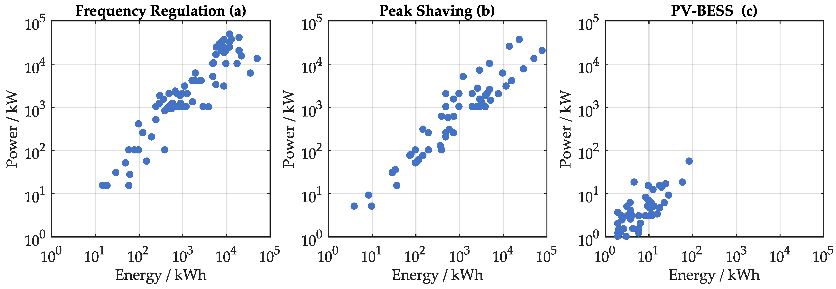
4.2. Analysis of BESS Operation in Selected Grid Applications

Figure 8 summarizes real world project data obtained from publicly available databases of PV-BESS and utility scale battery storage projects [86,172]. The analysis reveals storage system size and power-to-energy ratio for three selected use cases (Primary Control Reserve (PCR) frequency regulation, residential PV-BESS and industrial PS): The ordinate indicates the nominal power for the associated BESS on a logarithmic scale. The abscissa depicts nominal energy of the BESS on a logarithmic scale. Despite not visualized in the figure, analysis of the databases also underlines that over 75% of PV-BESS products and utility scale projects listed rely on NMC:C, NCA:C or LFP:C battery technologies.
For frequency regulation (cf. Figure 8a) most projects have nominal power of above 1 MW and follow a P:E ratio of approximately 1:1, but values spread out to either side. This is attributed to local regulatory constraints forcing minimum size for market participation and/or minimum required nominal energy for serving this power application [127]. Requirements of fast reaction speed and steep ramp rates result in high power capability requirements for the BESS which may be challenging for both batteries and power electronics of the system [132]. It is speculated, that deviating data points with lower power to energy ratio may include BESS projects serving combined applications (e.g., PCR plus local grid support, PCR plus UPS, etc.) and therefore some statistical outliers can be found. Pooling concepts may allow for smaller storage units (≤1 MW) to participate in regulated PCR markets, also.
LIB based storage systems analysis serving PS applications (cf. Figure 8b) reveal sizes between a few ten kWh up to several MWh. The high variations observed are attributed to highly individual demand patterns of industrial customers. Power to energy ratios between 4:1 and 1:4 are typical for the BESS projects analyzed, matching well the task of PS storage systems to balance short term load fluctuations over a DSO specified averaging time window of typically 15 min to 1 h [143]. Outliers showing lower power to nergy ratio may be attributed to regions with distinct regulatory constraints, load patterns requiring extended storage dispatch or combined applications (e.g., PS plus PV self consumption, PS plus UPS, ect.).
As apparent form Figure 8c, LIB storage used for PV-BESS show a distinct characteristics: the BESS used to increase self-consumption of prosumer residential households feature storage size ranging from approximately 1 kWh up to a few ten kWh. the power to energy ratio is typically found below 1:1. A more detailed analysis reveals, that system size is highly dependent on both PV-system size and the households energy consumption [42,137]. The requirements of maximum power to energy ratio (and resulting battery C-rate) are significantly lower in comparison to other applications; the storage main task of daytime to nighttime energy shift results in an overall low power requirement [173].
For a more detailed discussion of requirement specifications for BESS, simulation data of the storage operation in an exemplary showcase for each of the three depicted applications (PCR, PS, and PV-BESS) is analyzed in detail. Simulations data was taken from previous investigations of battery storage operation (PCR [132], PS [174] and PV-BESS [13]) and is based on common naive controller operation strategies with no forecast or integrated dispatch optimization. Figure 9 shows histogram plots (with logarithmic y-axis) of the three datasets evaluated for a full year of simulated operation: While the upper diagrams (Figure 9a–c) shows the relative frequency count of battery SOC, the lower panels (Figure 9d–f) depict the relative frequency count of the C-rate for the identical storage systems. Positive C-rate values refer to charging, negative values to discharging of the BESS.
As described in Section 4.1.1, BESS in PCR frequency regulation have to compensate for short term (milliseconds to a few seconds) grid-fluctuations. Therefore, the rest-state SOC is forced to near 50% to be prepared for fluctuations on either side with a slight offset accounting for nonunity conversion efficiency of the BESS [132]. The analysis of C-rate (cf. Figure 9d), revels on average a moderate cycle duty (C-rate ≤±0.5 C in more than 97% of the time) with few excitations. The SOC swing is low, and rarely exceeds a DOD of ± 20 % . Referring to the aging of LIB (cf. Section 2.2), low DOD cycles commonly result in minor cyclic aging effects and a dominance of calendric aging is anticipated. This finding is well in line with previous aging analyses on PCR storage systems and underlines the importance of calendar aging awareness particularly at intermediate SOC level (being sensitive to choice of LIB cell and the system’s thermal management concept) for PCR storage systems in order to achieve desired long project lifetimes [132].
As apparent from Figure 9b, a simple control strategy for BESS in a peak shaving application may lead to SOC values near 100% at almost all times: Similar to UPS storage systems, for PS the system is at full state during stand-by, if no particular forecast-based control strategy is applied. As discussed earlier (cf. Section 2.2) such high rest state SOC of LIB may lead to prominent calendric aging. In case unexpected load peaks are to be shaved the storage system needs to react with rapid high power delivery from the battery systems. Accordingly, the spectrum analysis (cf. Figure 9e reveals few peaks of high C-rate (1.2% of the time with C-rate ≥ ± 1 , peak at −3.5 C). In summary, LIB storage systems developed for peak shaving application are required to withstand high C-rates and cope with high SOC rest states. In fact, a closer view on the PS profile matching the particular customer data analyzed herein, reveals that only a few peaks are to be shaved resulting in less than ten full equivalent cycles over the course of one year. In this particular case, cycle performance of the LIB may not be an issue and the focus is on calendar aging mostly. In general, it may be worth to optimize the storage dispatch strategy with an aim to lower average SOC in order to reduce calendar aging effects [174]. This may allow avoiding high replacement cost for batteries (cf. C d e g r a d e in Equation (1)) within a typical PS project lifetime of 10 years and more.
For PV-BESS application a direct charge/discharge (“greedy”) operation of a typically sized residential battery storage system ( E N B E S S = 5 kWh) leads to a SOC probability distribution spectrum as is shown in Figure 9c. Two characteristic points within the SOC spectrum are apparent, being full state (SOC 100 % ) and empty state (SOC 0 % ). With about 200 Full Equivalent Cycles (FEC) charge throughput the cycle count on the battery cell level is found higher when compared to the aforementioned application use cases PCR and PS. The non-symmetric C-rate diagram (cf. Figure 9f) reveals a higher battery duty during charge (PV surplus) compared to overall low C-rates for discharge caused by residential load demand (based on a smart meter data derived household load profile [175]). It remains a challenge for state-of-art LIB systems to meet the requirements of PV-BESS of desired long product lifetime comparable to that of photovoltaic generators (up to 20 years) taking into account the full DOD swing and wide distribution of SOC states as well as the high amounts of charge throughput at the low to moderate C-rates typically observed. Similar to PS application, it may be of interest reduce the dwell time at high SOC of PV-BESS using appropriate controller strategies [138]. This will be discussed in more detail in the following Section.
In conclusion, the selected use cases exemplary depicted in Figure 9 reveal the importance of dedicated analysis of battery operation in a specific use case scenario. The individual load patterns derived for each application may reveal distinct requirements for the BESS and particularly the performance parameters of the LIB cells to be used. Note that simulation data shown here may not be optimal from a battery degradation and overall economic point of view: System modelling and tailored storage dispatch optimization is required to maximize the value of a storage system in a given application use case, as is discussed in more detail in the following (cf. Section 5).

4.3. Future Developments

Combining applications may play an important role in the future, as stacking of applications allows increasing profits of a storage system. However, finding suitable BESS control strategies for stacking of applications may be challenging and it should be noted, that in various cases regulatory constraints hinder the usage of a singular BESS for multiple applications if more than one stakeholder is involved. Furthermore, performing application tasks by pooling and coordinated control of multiple distributed storage systems may be of interest in a future power grid with more BESS installed at various locations [176]. Bi-directional V2G is a particularly challenging example but starts to become more frequently discussed in academia with an industrial context [119,177].

5. Simulation and Optimization for Stationary Battery Storage Systems

While Section 3 of this review provides an overview to battery topology and storage system design, Section 4 lists a variety of BESS applications and attainable profits. For functional storage system operation, combining the requirements of the application with the choice of an appropriate system design is a key prerequisite. For a cost-efficient project realization, sizing, positioning and power flow control are to be analyzed and specifically optimized. This Section aims to briefly review both modeling tools readily available for the analysis of BESS in different applications with a sensitivity to various parameters and discusses few optimization challenges frequently found in the context of BESS grid integration.

5.1. Simulation and Modelling of Storage Systems

Despite model supported analysis of stationary storage systems has been conducted for specific storage technologies and/or applications [137,178], little work exists, that summarizes well the existent modeling and simulation methods. Several distinct objectives often require specific approaches. A non-comprehensive overview to some readily available modeling tools with their respective aim, strengths, and shortcomings is presented in Table 6. Additional information and a summary of tool-specific highlights is presented subsequently. The Table also provides information to user interface and availability of source code. It is worth to mention, that in recent years open modeling approaches and publicly available tools (“free to download”) have attained a significant interest in the energy sector, as they are freely available to both academia and industry and allow a co-development of model tool-kits with a larger community [179,180]. A similar trend might arise for battery storage modeling. PerModAC was developed by researchers at the University of Applied Sciences Berlin (HTW Berlin, Germany) to model the efficiency of PV-BESS systems. While the model features an integrated approach including all components relevant for efficiency-modelling of PV-BESS (i.e., battery, inverter, stand-by, and EMS control), the tool is confined to AC-coupling of BESS and does not allow modeling of battery aging in its present version. The Matlab-based program code is available free of charge to registered users, enabling widespread distribution and continued development by researchers interested. The documentation is in German language only [181].
The Storage Value Estimation Tool (StorageVET) was developed by the US Electric Power Research Institute (EPRI) and focuses on the profitability analysis for utility-scale storage projects. The web-based tool allows a straightforward value estimation for BESS based on a set of predefined technical and economical input parameters. It aims to allow for a fair comparison of profitability for storage projects in different (utility scale) grid services, among different technologies and sizes as well as locations. For battery type specific modeling, the tool is limited to a generalized approach of formalized parameters (i.e., battery efficiency, SOC constraints, cycle and calendar lifetime estimations) and does not include LIB technology specific models. Interestingly, value stacking (i.e., a multi-use application) of storage systems is specifically addressed. StorageVET can be used at the interface with power flow modeling tools via import/export of storage dispatch variables [182].
BLAST (Battery Lifetime Analysis and Simulation Tool) is a toolkit provided by the US National Renewable Energy Laboratories (NREL). The focus lies on LIB modeling, based on detailed battery aging degradation analysis and functionality to long-term battery lifetime prediction. For usage in automotive and stationary applications several specialized variants exist (e.g., BLAST-BTM for PS application, BLAST-S for other utility-scale applications). For example, BLAST-BTM provides a predefined user interface that allows convenient battery sizing optimization in a PS application. However, the adaptability to variations of storage parameters (e.g., topology of batteries, inverter system) is very limited. PV-BESS application is not focused at present. Only some variants are available for free download (executable code with GUI interface) and support is limited to the documentation provided [96].
SimSES (Simulation of Stationary Energy Storage Systems) is a modular object-oriented tool-chain initiated and coordinated by researchers at Technical University of Munich (Germany). The Matlab-code based toolkit allows holistic technical and economic modeling of storage systems in variable applications. It features pre-implemented battery models (e.g., variants of LIB cells), includes storage system and grid integration components (e.g., thermal management, power electronics components) and some exemplary use-cases (e.g., PV-BESS, utility scale control reserve). Due to the open-modeling approach and freely available source code, the integration of new features and variants is feasible with ease. At present there exists no GUI or web interface, but SimSES objects can be directly accessed via the Simulink graphical modeling environment [183].
HOMER (Hybrid Optimization of Multiple Energy Resources) originally developed by NREL is available as commercial tool for modeling and optimization of MG featuring fossil generation, renewable power sources, storage, and load management. As such, the focus is not on the battery itself but on the full grid level. For MG applications, straightforward cost optimization is feasible using HOMER and storage system modeling features estimation of efficiency, self-discharge and aging. The commercial tool features a free trial version and a web-based tool access [184,186].
SAM (System Advisor Model) is a tool specifically designed for modeling of PbA and LIB in PV-BESS applications. The battery modeling is based on detailed capacity, voltage, thermal and lifetime sub-models, which can be parametrized e.g., using battery data sheets. In order to execute time-series calculations it requires user-defined operation strategies. In conjunction with financial modeling parameters, SAM allows a straightforward techno-economic analysis. Similar to aforementioned PerModAC, in its present version, SAM is limited to AC coupling of storage [185].
In summary, various tools for modeling of LIB in stationary applications are available to date. These tools have a distinct aim and show individual strength and drawbacks as summarized in Table 6. Despite solving related optimization problems is partly feasible with some tools listed, typical optimization challenges involving BESS grid applications are complex and require specifically tailored and proprietary code design, which will be analyzed next.

5.2. Optimization Tasks for Usage of BESS in BTM and Grid Applications

While the modeling tools presented allow for generalized and simple ab-initio calculations of technical and economical parameters for LIB based storage projects, various challenges can only be tackled using specifically adapted optimization techniques. This work does not aim to give a comprehensive guide to the broad field of optimization, but shall solely mention a number of solution techniques often used in the context of BESS grid integration. The benefit of BESS is highly affected by various degrees of freedom including BESS sizing and system component composition, optimal placement in a grid infrastructure as well as the storage dispatch and control obeying the application(s) of choice. Various different approaches have been proposed in literature for such optimization challenges both in the simulation and planing as well as the operation phases.
In a first step, optimization criteria and cost function formulation have to be defined: apart from revenue maximization, other optimization goals have been defined and analyzed such as C O 2 impact minimization [187] and—to a lesser extent—efficiency optimization (i.e., minimization of heat dissipation) [177].
While methodologies for sizing and control have been reviewed previously specifically for a MG context [188], a more comprehensive overview of optimization algorithms and their usage in context of distribution grid planning has been provided by others [124]. Only recently a detailed review dedicated specifically to the energy management of stationary BESS has been given by Weitzel et al. [10]. Similar to their work, a categorization of solution techniques for BESS related optimization problems is provided in Table 7. In brief, the computational approaches used can be distinguished according their algorithmic complexity: Straightforward programming approaches based on sensitivity studies or iterative methods may circumvent optimization techniques and screen the solution space step-by-step via iterative execution. Gradient methods and deterministic optimization techniques allow for better accuracy and faster computing but may be used only if the optimization problem can be formulated adequately. Linear Programming (LP), Mixed Integer Linear Programming (MILP) Non-Linear Programming (NLP), and Dynamic Programming (DP) methods have been identified within this group. Stochastic and meta-heuristic methods are commonly more demanding in computing power and require sophisticated parametrization. These are listed along with real-time control approaches as the problem sets often involve uncertainty (variable forecasts of load and generation; interplay of multiple units in a MG, ect.). To solve the complex problems various algorithmic approaches have been proposed, e.g., Fuzzy Logic Control (FLC), Genetic Algorithm (GA), Particle Swarm Optimization (PSO), Inventory Model (InvM), Model Predictive Control (MPC).
We distinguish among these algorithmic approaches separately with respect to the optimization goal of best suited sizing, placing or dispatching the storage unit and show which applications were addressed in the exemplary work analyzed. After a brief discussion of some highlighted papers, present and future developments in the field of modeling and optimization for application stacking (multi-use) and multi-storage concepts are discussed separately (cf. Section 4.1.5).

5.3. Sizing of BESS

An appropriate sizing of both energy content and rated power capability of a BESS is of uttermost importance. For cost competitive project realization the project ROI is to be optimized, i.e., a fair balance between investment cost ( C i n v ), operational cost ( C O P E X ), degradation related cost ( C d e g r a d e ) and attainable profit ( P A P L ) has to be found (cf. Equation (1)). Various computational approaches have proven to meet application-specific challenges: Optimal sizing of a BESS in PCR application was studied in detail by Oudalov et al. [143]: The authors use a rule-based BESS dispatch approach matching European UCTE grid constraints for control reserve provision and execute various cost-profit optimization runs based on a historical data analysis. They demonstrate the BESS for provision of ancillary services and give an appropriate control method based on the current battery SOC. A later work on battery storage based provision of control reserve by Borsche et al. [131] demonstrates how set-point adjustments can be implemented algorithmically and evaluate a technical minimum of necessary power and energy content for the BESS based on historic data analysis. However, it is important to note, that for various markets minimum required capacity is subject to regulations. A comprehensive sensitivity analysis of battery and inverter size for battery home-storage systems with respect to self-sufficiency and cost has been presented by Weniger et al. [189]. The sensitivity study reveals the suitability of state-of-art battery and inverter systems for a PV-BESS application depending on a customer’s load profile and PV generation. Aging aware cost-optimal sizing of inverter and storage systems for PV-BESS can also be derived via linear programming approaches [42]. However, this approach requires linearization and thus simplification of aging cost functions when applied to LIB. A different approach has been chosen by Schneider et al. [202] demonstrating the applicability of inventory models to find near-optimal storage sizing whilst being able to cope with load and generation uncertainty. Other recent work investigates the usage of a community energy storage system for optimized self-consumption of multiple households - the sensitivity analysis reveals optimal sizes for PbA and LIB systems [191]. In fact, in various contributions sizing of storage is combined with a secondary objective (e.g., combined sizing and placement [190,196,199], or combined sizing and dispatch optimization PS [128]). These approaches are discussed in the following Subsections.

5.4. Placement of BESS

As identified by Hoffman et al. [204], until recent only little work was available analyzing optimal placement of storage systems in power grids. An integrated approach for BESS sizing and placement in a MG context based on metaheuristic particle swarm optimization techniques was recently presented by Sedghi et al. [199]. Others have analyzed the optimal placement and sizing of a community BESS in a multi-objective grid support function: Geth et al. [196] uses a genetic algorithm approach and pareto-optimal frontier detection techniques to optimize the impact of BESS integration with respect to multiple conflicting interests of the storage stakeholders and the DSO. A subsequent work by Tant et al. [192] takes into account the active and reactive power flow within the modeled sample grid and is based on full profile data knowledge. A more recent work by Karanki et al. [190] investigates optimal capacity and placement of BESS in an exemplary distribution network based on dissipation loss minimization. The non-linear optimization problem was solved using a PSO-based algorithm converging within few iterations.

5.5. Dispatch of BESS

Some typical heuristic and rule-based approaches for storage system control, have been analyzed in context of prominent application examples (cf. Section 4.2). A challenging task to overcome, when optimizing the battery dispatch (i.e., the charge/discharge behavior) is the strong non-linearity and functional complexity of storage performance parameters (e.g., rate-capacity effect, aging-induced capacity fade), their sensitivity to external parameters (e.g., temperature), and the uncertainty of application derived power requirements. In most approaches, only some depicted aspects of the potential parameter variability is analyzed and optimized. For example, dynamic programming approaches were applied successfully to achieve the complex tasks of combined sizing and dispatch optimization in PS [128]. However, unperturbed historical load data was used as a storage input and aging was not modeled. In fact, a more recent paper demonstrates how DP approaches can also be used for a residential storage application including a simple linear calendric aging model [193]. Koller et al. [201] introduced a DOD dependent battery aging cost function to determine an optimized BESS operation in a PS application. Such definition of an explicit cost function may prove very valuable for deterministic optimization and real-time control of a storage unit: e.g., Goebel et al. [136] studied different control strategies suited for secondary control reserve trading with battery storage based on an aging-averse cost function. While the electro-thermal cell model allows monitoring calendric and cyclic aging effects the controller model is trained with historic data but may cope with unforeseen variations of application demand and profit.
Load uncertainty and forecasting methods are of extraordinaire importance for the optimal performance of predictive BESS dispatch control strategies. These are investigated in more detail in various contributions : A comprehensive dispatch optimization with respect to external influencing parameters like feed-in tariff or time of use tariff for a residential battery storage system is given e.g., by [194]. Persistence based controller strategies for PV-BESS in different coupling topologies have been proposed and demonstrated allowing e.g., to lower dwell time at high SOC in order to minimize calendric aging effects whilst maintaining similar profitability [138,197]. Bergner investigates in detail, how improved PV-BESS control strategies could reduce power feed in to the distribution grid [198]. Like most contributions optimizing BTM storage operation, this work however does not reflect back-coupling effects of storage integration to the overlying grid structure. Analysis of this aspect has been analzed in more detail in a MG context: For example, Pegueroles-Queralt et al. [203] developed a control strategy for MG connected AC/DC inverters coupled to BESS aiming to optimize the switching control of power converter units within the system.
In context of the Internet of Things (IoT) an increasing number of decentralized systems with distributed control also the interplay of multiple storage systems to fulfilling one or more tasks has attained more interest in recent years. The operational control of the energy management within such multi-player systems is a challenging task with various degrees of freedom. Coordinated [205] and non-coordinated [206,207] methods have been proposed to cope with the control challenges. Others have proposed and simulated combined control methods (local, distributed and central control) for voltage and load manaement in a distribution network [208]. Coordinated charge control for V2G support of power grids has also been analyzed and optimited—e.g., Singh et al. [200] demonstrated coordinated control of vehicle and charging stations using a FLC based algorithm in a real time scenario.

6. Results and Future Directions for Research

This review paper analyzes technical concepts of LIB based storage systems and grid interface with respect to their applicability for stationary applications. The main findings can be summarized as follows:
  • A simple generic formula is proposed for profitability analysis of BESS: It takes into account cost and revenue attainable by the integration of battery storage systems in stationary applications. Technical parameters of the storage system (e.g., battery aging and system efficiency) have to considered on the cost side. Revenues are determined by the application of choice. For profit maximization, trade-off between cost and revenue is to be found via choice of best suited battery technology, suitable storage system design as well as optimization of several degrees of freedom named below.
  • To date, LIB cell development has been driven mostly by the automotive industry and portable devices, pushing mainly for peak power performance and higher energy density. As requirements of stationary applications are distinct, the suitability of current and future LIB cell technologies are to be reviewed. Technical parameters of three state-of-art LIB technologies (NMC:C, NCA:C and LFP:C) are assessed with respect to applicability of implementation in stationary storage: Each show individual strength and drawbacks. Interesting candidates for next generation of LIB cells are briefly analyzed, but a technology scoring better in all performance indicators identified for stationary systems seems not in sight for the near future.
  • Both battery aging and overall system efficiency losses are identified as prominent cost drivers for today’s LIB based stationary storage systems. A better understanding of the cell internal degradation mechanisms as well as system topology optimization will be detrimental for improved system design with better performance: The full potential of the system can only be accessed if a holistic approach is chosen already early in the design phase.
  • To assess among various system topologies and thermal concepts available for BESS, it is important to define test protocols and monitor the system behavior in the desired application use-case. Ab-initio modelling using tools available to the public may help to serve the task of selecting best components for a specific LIB based stationary storage project.
  • Second-life and particularly second-use (i.e., integration of used and virgin automotive battery packs for stationary applications) concepts are seen as a potential driver for more cost competitive large-scale storage systems. Technical challenges of system integration based on these concepts are yet to be addressed.
  • Application classification: A classification of BESS applications to four main categories is proposed: Ancillary service, Behind the meter, Energy trading, and Investment deferral & Local grid support. Combined applications (i.e. value stacking of aforementioned applications, island-grid/microgrid, and V2G applications) are also discussed in this context: These are assumed particularly relevant for both revenue optimization and compatibility with future power-grids.
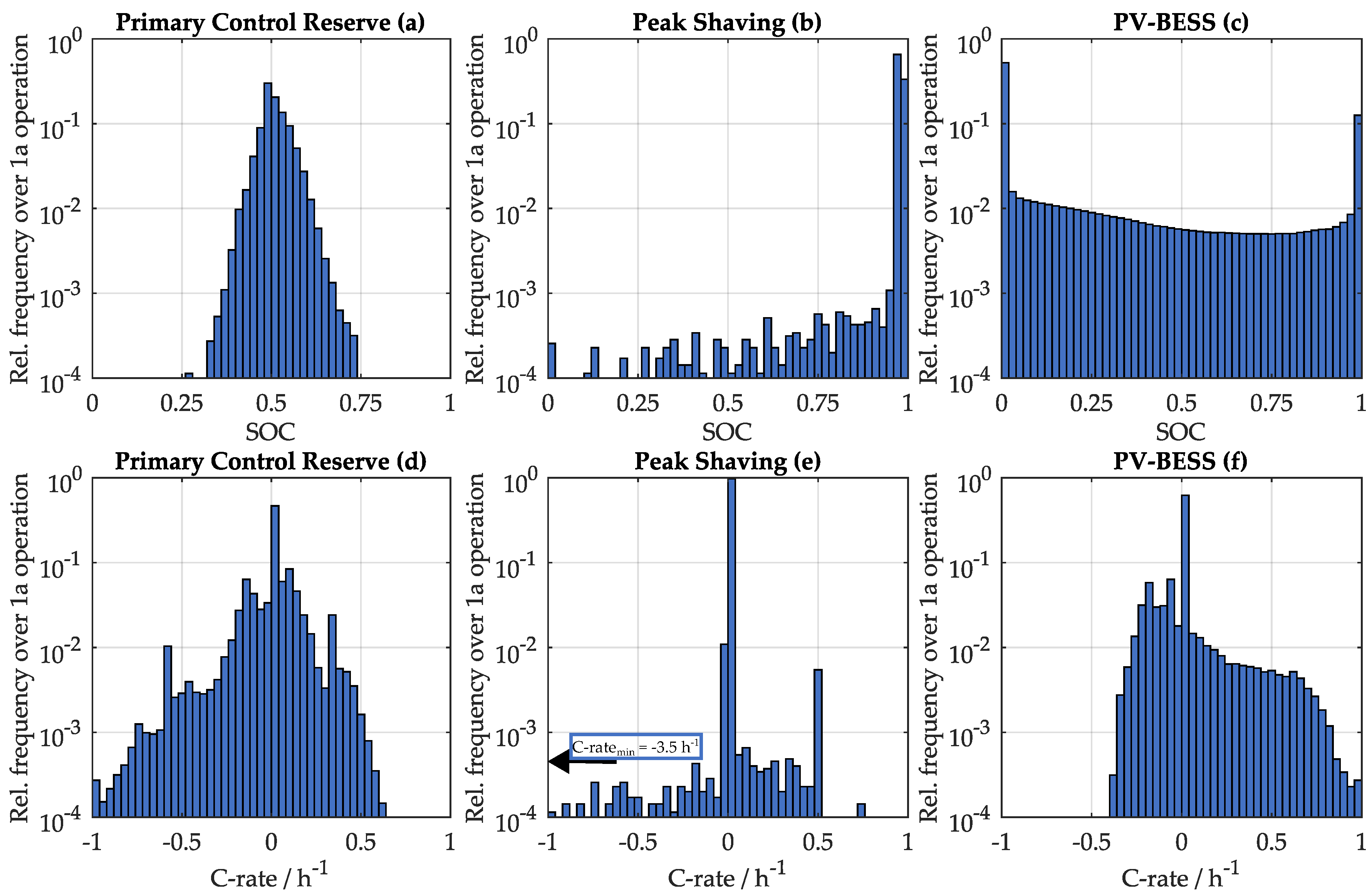
  • Application analysis: within the application families three typical use cases are selected (PCR, PV-BESS and PS) and storage operation in these applications is analyzed via simple data analysis. A link to battery technology, system design and optimization is provided, as the applications require distinct cell and system features.
  • A set of publicly available modelling tools for technical and economic assessment of BESS is compared. Individual features and limitations are named; the authors believe, that open-source modelling approaches will allow not only for widespread model usage but also improvement and refinement of tool-chains necessary for next-generation stationary storage systems.
  • System optimization and control: To access the full potential of a BESS in a desired application, various optimization tasks are to be addressed: Contributions considering the sizing of storage, the placement of system and the dispatch strategy for the BESS unit are reviewed and grouped according algorithmic approach and application use-case studied.
  • Sizing related challenges are highly use case specific and were studied with numerous different algorithmic approaches. Placement related challenges are often discussed in a micro-grid/local distribution grid related context, combined (multi-objective) approaches of sizing and placement rely on stochastic/metaheuristic algorithms.
  • For optimal system operation a sophisticated EMS control is required. It should be aware of forecast errors, battery specific parameters, system topology and thermal concept as well as application constraints. None of the literature reviewed can cope with all the above criteria simultaneously. However, interesting approaches tackle a subset of dispatch optimization related challenges with either deterministic or (more frequently), meta-heuristic approaches. It is believed, that particularly real-time control of BESS will be a focus area of future research—possibly linked to data-driven model refinement.
Apart from these current developments pointed out a few more speculative future developments are mentioned in this review. Future directions of R&D driven developments for stationary battery storage systems might include:
  • Driven by overwhelming demand for LIB cells in the automotive sector, an increased tailoring of LIB cell development towards performance indicators suitable for vehicular requirements is supposed: Pursuing lower investment cost per kilowatt-hour, this could be at the cost of a lower calendar and particularly cycle lifetime. Also development for new cell technologies fulfilling these requirements (e.g., potentially LiS) might overtop development of cells potentially favored for stationary applications (e.g., LTO:MOX). As such, aging aware storage system design and operation might be of increased importance for future stationary LIB storage projects.
  • At the system level, TCO-driven project realization might underline the importance of system efficiency and dissipative losses. Multi-level converters could be a breakthrough technology, if produced at reasonable cost, as these may allow boosting the efficiency attainable on the system level.
  • Despite the anticipated LIB industry-leading role of automotive developments, not all related concepts discussed in this review are projected to obtain breakthrough: V2G and second-life battery re-use concepts demand profound battery knowledge extensive R&D on the system level (to overcome today’s technical challenges). Despite low initial investment costs, the absolute cost advantage might fade. Assembling off-the-shelf automotive packs for stationary systems might be a viable option for short to mid-term, and could pave the way to future battery module and pack concepts compatible with direct usage in both automotive and stationary systems.
  • The digitization and the Internet of Things (IoT) are believed to rapidly penetrate the energy sector including storage devices. As such, R&D should analyze further operation concepts of distributed and small to mid-scale BESS for grid-scale applications.
In Summary, various technical improvements are in sight for all contributing areas discussed in this review including Lithium-ion battery technology, storage system design, and control. However, in order to exploit the full potential of BESS for stationary applications, it will be detrimental to link the technical features of BESS to application and grid framework via simulation and modeling approaches. Validation of such models using real-world data will help to further improve the system design and better match the requirements of a future power system.

Acknowledgments

The authors thank Ulrich Bürger and his team at Smart Power GmbH for fruitful discussions on battery storage system design and applications. The authors also thank J. Weller for supporting this work through his study on BESS installed in Germany. Nam Truong’s effort for reviewing the Section on optimization methods is also gratefully acknowledged. The research project IHEM is funded by the Federal Ministry for Economic Affairs and Energy within the Funding initiative Electrical Storages (grant number 03ET1205G). This work was supported by the German Research Foundation (DFG) and the Technical University of Munich (TUM) in the framework of the Open Access Publishing Program.

Author Contributions

H.H. was the principle author tasked with coordinating and writing the review; M.S. wrote contents on the battery storage system design; D.K. wrote contents on battery applications. Both M.S. and D.K. helped with gathering data and formatting graphs. A.J. contributed with input on Lithium-ion battery technology and via fruitful scientific discussions.

Conflicts of Interest

The authors declare no conflict of interest.

Abbreviations

ACAlternating Current.
B-TMSBattery-TMS.
BESSBattery Energy Storage System.
BMSBattery Management System.
BTMBehind-the-Meter.
CCarbon-Graphite.
CHCharge.
DCDirect Current.
DCHDischarge.
DOCDepth of Cycle.
DODDepth of Discharge.
DPDynamic Programming.
DSODistribution System Operator.
ECMEquivalent Circuit Model.
EMSEnergy Management System.
ESSEnergy Storage Systems.
EVElectric Vehicles.
FECFull Equivalent Cycles.
FLCFuzzy Logic Control.
GAGenetic Algorithm.
HVHigh-Voltage.
InvMInventory Model.
IoTInternet of Things.
ISOIndependent System Operator.
LCOELevelized Cost of Electricity.
LFPLithium-Iron-Phosphate.
LIBLithium-Ion Battery.
LiSLithium-Sulfur.
LPLinear Programming.
LTOLithium-Titanate-Oxide.
LVLow-Voltage
MGMicro-Grid.
MILPMixed Integer Linear Programming.
MOXMetal-Oxide.
MPCModel Predictive Control.
MPPTMaximum Power Point Tracker.
MVMedium-Voltage.
NaSSodium(Na)–Sulfur Battery.
NCANickel-Cobalt-Aluminum-Oxide.
NLPNon-Linear Programming.
NMCNickel-Manganese-Cobalt.
OCVOpen Circuit Voltage.
PbALead(Pb)-Acid.
PCMPhysical-Chemical Models.
PCRPrimary Control Reserve.
PSPeak Shaving.
PSOParticle Swarm Optimization.
PVPhotovoltaic.
PV-BESSResidential Photovoltaic Battery Storage System.
RESRenewable Energy Sources.
ROIReturn on Investment.
S-TMSSystem-TMS.
SCADASupervisory Control and Data Acquisition.
SEISolid Electrolyte Interphase.
SOCState of Charge.
SOHState of Health.
TCOTotal Cost of Ownership.
TMSThermal Management System.
UPSUninterruptible Power Supply.
V2GVehicle-to-Grid.
XHVExtra-High-Voltage.

References

  1. Dincer, I. Renewable energy and sustainable development: A crucial review. Renew. Sustain. Energy Rev. 2000, 4, 157–175. [Google Scholar] [CrossRef]
  2. REN21 Secretariat. Renewables 2017: Global Status Report; REN21 Secretariat: Paris, France, 2017. [Google Scholar]
  3. Carrasco, J.M.; Franquelo, L.G.; Bialasiewicz, J.T.; Galvan, E.; PortilloGuisado, R.C.; Prats, M.; Leon, J.I.; Moreno-Alfonso, N. Power-Electronic Systems for the Grid Integration of Renewable Energy Sources: A Survey. IEEE Trans. Ind. Electron. 2006, 53, 1002–1016. [Google Scholar] [CrossRef]
  4. Chen, H.; Cong, T.N.; Yang, W.; Tan, C.; Li, Y.; Ding, Y. Progress in electrical energy storage system: A critical review. Prog. Nat. Sci. 2009, 19, 291–312. [Google Scholar] [CrossRef]
  5. Dunn, B.; Kamath, H.; Tarascon, J.M. Electrical Energy Storage for the Grid: A Battery of Choices. Science 2011, 334, 928–935. [Google Scholar] [CrossRef] [PubMed]
  6. Luo, X.; Wang, J.; Dooner, M.; Clarke, J. Overview of current development in electrical energy storage technologies and the application potential in power system operation. Appl. Energy 2015, 137, 511–536. [Google Scholar] [CrossRef]
  7. Vazquez, S.; Lukic, S.M.; Galvan, E.; Franquelo, L.G.; Carrasco, J.M. Energy Storage Systems for Transport and Grid Applications. IEEE Trans. Ind. Electron. 2010, 57, 3881–3895. [Google Scholar] [CrossRef]
  8. Ferreira, H.L.; Garde, R.; Fulli, G.; Kling, W.; Lopes, J.P. Characterisation of electrical energy storage technologies. Energy 2013, 53, 288–298. [Google Scholar] [CrossRef]
  9. IRENA. Electricity Storage and Renewables: Costs and Markets to 2030: International Renewable Energy Agency; IRENA: Abu Dhabi, UAE, 2017. [Google Scholar]
  10. Weitzel, T.; Glock, C.H. Energy Management for Stationary Electric Energy Storage Systems: A Systematic Literature Review. Eur. J. Oper. Res. 2018, 264, 582–606. [Google Scholar] [CrossRef]
  11. Nykvist, B.; Nilsson, M. Rapidly falling costs of battery packs for electric vehicles. Nat. Clim. Chang. 2015, 5, 329–332. [Google Scholar] [CrossRef]
  12. Schmidt, O.; Hawkes, A.; Gambhir, A.; Staffell, I. The future cost of electrical energy storage based on experience rates. Nat. Energy 2017, 6, 17110. [Google Scholar] [CrossRef]
  13. Truong, C.N.; Naumann, M.; Karl, R.C.; Müller, M.; Jossen, A.; Hesse, H.C. Economics of Residential Photovoltaic Battery Systems in Germany: The Case of Teslas Powerwall. Batteries 2016, 2, 14. [Google Scholar] [CrossRef]
  14. Naumann, M.; Karl, R.C.; Truong, C.N.; Jossen, A.; Hesse, H.C. Lithium-ion Battery Cost Analysis in PV-household Application. In Proceedings of the 9th International Renewable Energy Storage Conference (IRES 2015), Düsseldorf, Germany, 9–11 March 2015; Volume 73, pp. 37–47. [Google Scholar]
  15. Branker, K.; Pathak, M.; Pearce, J.M. A review of solar photovoltaic levelized cost of electricity. Renew. Sustain. Energy Rev. 2011, 15, 4470–4482. [Google Scholar] [CrossRef]
  16. Battke, B.; Schmidt, T.S.; Grosspietsch, D.; Hoffmann, V.H. A review and probabilistic model of lifecycle costs of stationary batteries in multiple applications. Renew. Sustain. Energy Rev. 2013, 25, 240–250. [Google Scholar] [CrossRef]
  17. Rathgeber, C.; Lävemann, E.; Hauer, A. Economic top–down evaluation of the costs of energy storages—A simple economic truth in two equations. J. Energy Storage 2015, 2, 43–46. [Google Scholar] [CrossRef]
  18. Howells, M.; Rogner, H.; Strachan, N.; Heaps, C.; Huntington, H.; Kypreos, S.; Hughes, A.; Silveira, S.; DeCarolis, J.; Bazillian, M.; et al. OSeMOSYS: The Open Source Energy Modeling System: An introduction to its ethos, structure and development. Sustain. Biofuels 2011, 39, 5850–5870. [Google Scholar]
  19. Daniel, C.; Besenhard, J.O. Handbook of Battery Materials, 2nd ed.; Wiley: Weinheim, Germany, 2012. [Google Scholar]
  20. Yoshio, M.; Brodd, R.J.; Kozawa, A. Lithium-Ion Batteries; Springer: Berlin, Germany, 2009. [Google Scholar]
  21. Väyrynen, A.; Salminen, J. Lithium ion battery production. J. Chem. Thermodyn. 2012, 46, 80–85. [Google Scholar] [CrossRef]
  22. Nitta, N.; Wu, F.; Lee, J.T.; Yushin, G. Li-ion battery materials: Present and future. Mater. Today 2015, 18, 252–264. [Google Scholar] [CrossRef]
  23. Delacourt, C.; Safari, M. Mathematical Modeling of Aging of Li-Ion Batteries. In Physical Multiscale Modeling and Numerical Simulation of Electrochemical Devices for Energy Conversion and Storage; Franco, A.A., Doublet, M.L., Bessler, W.G., Eds.; Green Energy and Technology; Springer: London, UK, 2016; pp. 151–190. [Google Scholar]
  24. Han, X.; Ouyang, M.; Lu, L.; Li, J. A comparative study of commercial lithium ion battery cycle life in electric vehicle: Capacity loss estimation. J. Power Sources 2014, 268, 658–669. [Google Scholar] [CrossRef]
  25. Patry, G.; Romagny, A.; Martinet, S.; Froelich, D. Cost modeling of lithium-ion battery cells for automotive applications. Energy Sci. Eng. 2015, 3, 71–82. [Google Scholar] [CrossRef]
  26. Zaghib, K.; Dontigny, M.; Guerfi, A.; Charest, P.; Rodrigues, I.; Mauger, A.; Julien, C.M. Safe and fast-charging Li-ion battery with long shelf life for power applications. J. Power Sources 2011, 196, 3949–3954. [Google Scholar] [CrossRef]
  27. Warner, J. The Handbook of Lithium-Ion Battery Pack Design: Chemistry, Components, Types and Terminology; Elsevier: Amsterdam, The Netherlands, 2015. [Google Scholar]
  28. Burke, A.; Miller, M. Performance characteristics of lithium-ion batteries of various chemistries for plug-in hybrid vehicles. In Proceedings of the International Battery, Hybrid and Fuel Cell Electric Vehicle Symposium (EVS24), Stavanger, Norway, 13–16 May 2009. [Google Scholar]
  29. Julien, C.; Mauger, A.; Vijh, A.; Zaghib, K. Lithium Batteries: Science and Technology; Springer: Cham, Switzerland, 2016. [Google Scholar]
  30. Keil, P.; Schuster, S.F.; Wilhelm, J.; Travi, J.; Hauser, A.; Karl, R.C.; Jossen, A. Calendar Aging of Lithium-Ion Batteries. J. Electrochem. Soc. 2016, 163, A1872–A1880. [Google Scholar] [CrossRef]
  31. Samsung SDI. Basic Specification of 94 Ah Lithium-Ion Battery Cell; Samsung SDI: Seongnam-si, Korea, 2017. [Google Scholar]
  32. Panasonic. Data Sheet NCR18650B Lithium-Ion Battery Cell; Panasonic: Osaka, Japan, 2017. [Google Scholar]
  33. Murata. Data Sheet of Sony Fortelion US26650FTC1 Battery Cell; Murata: Kyoto, Japan, 2017. [Google Scholar]
  34. Toshiba Industrial Systems. Data sheet of Toshiba 20Ah SCiB Rechargable Battery Cell; Toshiba Industrial Systems: Kawasaki, Japan, 2017. [Google Scholar]
  35. Akinyele, D.; Belikov, J.; Levron, Y. Battery Storage Technologies for Electrical Applications: Impact in Stand-Alone Photovoltaic Systems. Energies 2017, 10, 1760. [Google Scholar] [CrossRef]
  36. Xu, J.; Lin, F.; Doeff, M.M.; Tong, W. A review of Ni-based layered oxides for rechargeable Li-ion batteries. J. Mater. Chem. A 2017, 5, 874–901. [Google Scholar] [CrossRef]
  37. Liu, W.; Oh, P.; Liu, X.; Lee, M.J.; Cho, W.; Chae, S.; Kim, Y.; Cho, J. Nickel-Rich Layered Lithium Transition-Metal Oxide for High-Energy Lithium-Ion Batteries. Angew. Chem. Int. Ed. 2015, 54, 4440–4457. [Google Scholar] [CrossRef] [PubMed]
  38. Jaffe, S.; Adamson, K.A. Advanced batteries for utility-scale energy storage lithium ion, sodium metal halide, sodium sulfur, flow, advanced lead-acid, and other advanced batteries: Global market analysis and forecasts. Rep. Navig. Res. 2014. Available online: http://www.navigantresearch.com/wp-content/uploads/2012/07/ABES-12-Brochure.pdf (accessed on 16 November 2017).
  39. Scrosati, B.; Garche, J. Lithium batteries: Status, prospects and future. J. Power Sources 2010, 195, 2419–2430. [Google Scholar] [CrossRef]
  40. Li, J.; Klee Barillas, J.; Guenther, C.; Danzer, M.A. A comparative study of state of charge estimation algorithms for LiFePO4 batteries used in electric vehicles. J. Power Sources 2013, 230, 244–250. [Google Scholar] [CrossRef]
  41. Naumann, M.; Schimpe, M.; Keil, P.; Jossen, A.; Hesse, H.C. Analysis and modeling of calendar aging of a commercial LiFePO4/graphite cell. J. Energy Storage 2017. submitted. [Google Scholar]
  42. Hesse, H.; Martins, R.; Musilek, P.; Naumann, M.; Truong, C.; Jossen, A. Economic Optimization of Component Sizing for Residential Battery Storage Systems. Energies 2017, 10, 835. [Google Scholar] [CrossRef]
  43. Sarasketa-Zabala, E.; Martinez-Laserna, E.; Berecibar, M.; Gandiaga, I.; Rodriguez-Martinez, L.M.; Villarreal, I. Realistic lifetime prediction approach for Li-ion batteries. Appl. Energy 2016, 162, 839–852. [Google Scholar] [CrossRef]
  44. Barré, A.; Deguilhem, B.; Grolleau, S.; Gérard, M.; Suard, F.; Riu, D. A review on lithium-ion battery ageing mechanisms and estimations for automotive applications. J. Power Sources 2013, 241, 680–689. [Google Scholar] [CrossRef]
  45. Vetter, J.; Novák, P.; Wagner, M.R.; Veit, C.; Möller, K.C.; Besenhard, J.O.; Winter, M.; Wohlfahrt-Mehrens, M.; Vogler, C.; Hammouche, A. Ageing mechanisms in lithium-ion batteries. J. Power Sources 2005, 147, 269–281. [Google Scholar] [CrossRef]
  46. Arora, P.; White, R.E.; Doyle, M. Capacity fade mechanisms and side reactions in lithium–ion batteries. J. Electrochem. Soc. 1998, 145, 3647–3667. [Google Scholar] [CrossRef]
  47. Wang, J.; Purewal, J.; Liu, P.; Hicks-Garner, J.; Soukazian, S.; Sherman, E.; Sorenson, A.; Vu, L.; Tataria, H.; Verbrugge, M.W. Degradation of lithium ion batteries employing graphite negatives and nickel–cobalt–manganese oxide + spinel manganese oxide positives: Part 1, aging mechanisms and life estimation. J. Power Sources 2014, 269, 937–948. [Google Scholar] [CrossRef]
  48. Ecker, M.; Gerschler, J.B.; Vogel, J.; Käbitz, S.; Hust, F.; Dechent, P.; Sauer, D.U. Development of a lifetime prediction model for lithium-ion batteries based on extended accelerated aging test data. J. Power Sources 2012, 215, 248–257. [Google Scholar] [CrossRef]
  49. Smith, K.; Saxon, A.; Keyser, M.; Lundstrom, B.; Cao, Z.; Roc, A. Life prediction model for grid-connected Li-ion battery energy storage system. In Proceedings of the IEEE 2017 American Control Conference (ACC), Seattle, WA, USA, 24–26 May 2017; pp. 4062–4068. [Google Scholar]
  50. Santhanagopalan, S.; Smith, K.; Neubauer, J.; Kim, G.H.; Pesaran, A.; Keyser, M. Design and Analysis of Large Lithium-Ion Battery Systems; Artech House: Norwood, MA, USA, 2014. [Google Scholar]
  51. Yang, X.G.; Leng, Y.; Zhang, G.; Ge, S.; Wang, C.Y. Modeling of lithium plating induced aging of lithium-ion batteries: Transition from linear to nonlinear aging. J. Power Sources 2017, 360, 28–40. [Google Scholar] [CrossRef]
  52. Kindermann, F.M.; Keil, J.; Frank, A.; Jossen, A. A SEI Modeling Approach Distinguishing between Capacity and Power Fade. J. Electrochem. Soc. 2017, 164, E287–E294. [Google Scholar] [CrossRef]
  53. Safari, M.; Morcrette, M.; Teyssot, A.; Delacourt, C. Multimodal physics-based aging model for life prediction of Li-ion batteries. J. Electrochem. Soc. 2009, 156, A145–A153. [Google Scholar] [CrossRef]
  54. Patsios, C.; Wu, B.; Chatzinikolaou, E.; Rogers, D.J.; Wade, N.; Brandon, N.P.; Taylor, P. An integrated approach for the analysis and control of grid connected energy storage systems. J. Energy Storage 2016, 5, 48–61. [Google Scholar] [CrossRef]
  55. Namor, E.; Torregrossa, D.; Cherkaoui, R.; Paolone, M. Parameter identification of a lithium-ion cell single-particle model through non-invasive testing. J. Energy Storage 2017, 12, 138–148. [Google Scholar] [CrossRef]
  56. You, G.W.; Park, S.; Oh, D. Real-time state-of-health estimation for electric vehicle batteries: A data-driven approach. Appl. Energy 2016, 176, 92–103. [Google Scholar] [CrossRef]
  57. Dubarry, M.; Vuillaume, N.; Liaw, B.Y. From single cell model to battery pack simulation for Li-ion batteries. J. Power Sources 2009, 186, 500–507. [Google Scholar] [CrossRef]
  58. Ramadass, P.; Haran, B.; White, R.; Popov, B.N. Mathematical modeling of the capacity fade of Li-ion cells. J. Power Sources 2003, 123, 230–240. [Google Scholar] [CrossRef]
  59. Schmalstieg, J.; Käbitz, S.; Ecker, M.; Sauer, D.U. A holistic aging model for Li(NiMnCo)O2 based 18650 lithium-ion batteries. J. Power Sources 2014, 257, 325–334. [Google Scholar] [CrossRef]
  60. Eddahech, A.; Briat, O.; Vinassa, J.M. Performance comparison of four lithium–ion battery technologies under calendar aging. Energy 2015, 84, 542–550. [Google Scholar] [CrossRef]
  61. Ecker, M.; Nieto, N.; Käbitz, S.; Schmalstieg, J.; Blanke, H.; Warnecke, A.; Sauer, D.U. Calendar and cycle life study of Li(NiMnCo)O2-based 18650 lithium-ion batteries. J. Power Sources 2014, 248, 839–851. [Google Scholar] [CrossRef]
  62. Sauer, D.U.; Wenzl, H. Comparison of different approaches for lifetime prediction of electrochemical systems—Using lead-acid batteries as example. J. Power Sources 2008, 176, 534–546. [Google Scholar] [CrossRef]
  63. Safari, M.; Morcrette, M.; Teyssot, A.; Delacourt, C. Life Prediction Methods for Lithium-Ion Batteries Derived from a Fatigue Approach. J. Electrochem. Soc. 2010, 157, A892. [Google Scholar] [CrossRef]
  64. Zinth, V.; von Lüders, C.; Hofmann, M.; Hattendorff, J.; Buchberger, I.; Erhard, S.; Rebelo-Kornmeier, J.; Jossen, A.; Gilles, R. Lithium plating in lithium-ion batteries at sub-ambient temperatures investigated by in situ neutron diffraction. J. Power Sources 2014, 271, 152–159. [Google Scholar] [CrossRef]
  65. Waldmann, T.; Wilka, M.; Kasper, M.; Fleischhammer, M.; Wohlfahrt-Mehrens, M. Temperature dependent ageing mechanisms in Lithium-ion batteries—A Post-Mortem study. J. Power Sources 2014, 262, 129–135. [Google Scholar] [CrossRef]
  66. Wang, J.; Liu, P.; Hicks-Garner, J.; Sherman, E.; Soukiazian, S.; Verbrugge, M.; Tataria, H.; Musser, J.; Finamore, P. Cycle-life model for graphite-LiFePO4 cells. J. Power Sources 2011, 196, 3942–3948. [Google Scholar] [CrossRef]
  67. Dubarry, M.; Liaw, B.Y.; Chen, M.S.; Chyan, S.S.; Han, K.C.; Sie, W.T.; Wu, S.H. Identifying battery aging mechanisms in large format Li ion cells. J. Power Sources 2011, 196, 3420–3425. [Google Scholar] [CrossRef]
  68. Keil, P.; Jossen, A. Charging protocols for lithium-ion batteries and their impact on cycle life—An experimental study with different 18650 high-power cells. J. Energy Storage 2016, 6, 125–141. [Google Scholar] [CrossRef]
  69. Sarasketa-Zabala, E.; Gandiaga, I.; Rodriguez-Martinez, L.M.; Villarreal, I. Calendar ageing analysis of a LiFePO4/graphite cell with dynamic model validations: Towards realistic lifetime predictions. J. Power Sources 2014, 272, 45–57. [Google Scholar] [CrossRef]
  70. Schimpe, M. Comprehensive Modeling of Temperature-Dependent Degradation Mechanisms in Lithium Iron Phosphate Batteries. J. Electrochem. Soc. 2017, 164. accepted. [Google Scholar]
  71. Zaghib, K.; Simoneau, M.; Armand, M.; Gauthier, M. Electrochemical study of Li4Ti5O12 as negative electrode for Li-ion polymer rechargeable batteries. J. Power Sources 1999, 81, 300–305. [Google Scholar] [CrossRef]
  72. Choi, J.W.; Aurbach, D. Promise and reality of post-lithium-ion batteries with high energy densities. Nat. Rev. Mater. 2016, 1, 16013. [Google Scholar] [CrossRef]
  73. Andrea, D. Battery Management Systems for Large Lithium-Ion Battery Packs; Artech House: Norwood, MA, USA, 2010. [Google Scholar]
  74. Zhang, J.; Ci, S.; Sharif, H.; Alahmad, M. Modeling Discharge Behavior of Multicell Battery. IEEE Trans. Energy Convers. 2010, 25, 1133–1141. [Google Scholar] [CrossRef]
  75. Baggu, M.; Smith, K.; Friedl, A.; Bialek, T.; Schimpe, M. Performance and Health Test Procedure for Grid Energy Storage Systems. In Proceedings of the IEEE Power and Energy Society (PES) General Meeting, Chicago, IL, USA, 16–20 July 2017. [Google Scholar]
  76. Lu, L.; Han, X.; Li, J.; Hua, J.; Ouyang, M. A review on the key issues for lithium-ion battery management in electric vehicles. J. Power Sources 2013, 226, 272–288. [Google Scholar] [CrossRef]
  77. Lawder, M.T.; Suthar, B.; Northrop, P.W.C.; De, S.; Hoff, C.M.; Leitermann, O.; Crow, M.L.; Santhanagopalan, S.; Subramanian, V.R. Battery Energy Storage System (BESS) and Battery Management System (BMS) for Grid-Scale Applications. Proc. IEEE 2014, 102, 1014–1030. [Google Scholar] [CrossRef]
  78. Yang, N.; Zhang, X.; Shang, B.; Li, G. Unbalanced discharging and aging due to temperature differences among the cells in a lithium-ion battery pack with parallel combination. J. Power Sources 2016, 306, 733–741. [Google Scholar] [CrossRef]
  79. Rao, Z.; Wang, S. A review of power battery thermal energy management. Renew. Sustain. Energy Rev. 2011, 15, 4554–4571. [Google Scholar] [CrossRef]
  80. Khateeb, S.A.; Amiruddin, S.; Farid, M.; Selman, J.R.; Al-Hallaj, S. Thermal management of Li-ion battery with phase change material for electric scooters: Experimental validation. J. Power Sources 2005, 142, 345–353. [Google Scholar] [CrossRef]
  81. Huber, C. Phase Change Material in Battery Thermal Management Applications. Ph.D. Thesis, Technical University of Munich, Munich, Germany, 19 April 2017. [Google Scholar]
  82. Fuhs, M. Market Survey of Battery Home Storage Systems. Available online: www.pv-magazine.de/themen/batteriespeicher/ (accessed on 16 November 2017).
  83. Schimpe, M. Energy efficiency evaluation of grid connection topologies for stationary battery storage systems. Unpublished work. 2018. [Google Scholar]
  84. Swissgrid Ltd. Grid—Transmission System—Grid Levels: Various Grid Levels Transport Electricity; Swissgrid Ltd.: Laufenburg, Schweizer; Available online: https://www.swissgrid.ch/swissgrid/en/home/grid/transmission_system/grid_levels.html (accessed on 16 November 2017).
  85. Müller, M.; Viernstein, L.; Truong, C.N.; Eiting, A.; Hesse, H.C.; Witzmann, R.; Jossen, A. Evaluation of grid-level adaptability for stationary battery energy storage system applications in Europe. J. Energy Storage 2017, 9, 1–11. [Google Scholar] [CrossRef]
  86. Huff, G. DOE Global Energy Storage Database. Available online: https://www.energystorageexchange.org/ (accessed on 16 November 2017).
  87. Klein, M.P.; Park, J.W. Current Distribution Measurements in Parallel-Connected Lithium-Ion Cylindrical Cells under Non-Uniform Temperature Conditions. J. Electrochem. Soc. 2017, 164, A1893–A1906. [Google Scholar] [CrossRef]
  88. Pires, V.F.; Romero-Cadaval, E.; Vinnikov, D.; Roasto, I.; Martins, J.F. Power converter interfaces for electrochemical energy storage systems—A review. Energy Convers. Manag. 2014, 86, 453–475. [Google Scholar] [CrossRef]
  89. Chatzinikolaou, E.; Rogers, D.J. A Comparison of Grid-Connected Battery Energy Storage System Designs. IEEE Trans. Power Electron. 2017, 32, 6913–6923. [Google Scholar] [CrossRef]
  90. Bragard, M.; Soltau, N.; Thomas, S.; de Doncker, R.W. The Balance of Renewable Sources and User Demands in Grids: Power Electronics for Modular Battery Energy Storage Systems. IEEE Trans. Power Electron. 2010, 25, 3049–3056. [Google Scholar] [CrossRef]
  91. Siemens AG. Sinamics S120 Grid Infeed Manual; Siemens AG: München, Germany, 2015. [Google Scholar]
  92. Bonfiglioli. Product Description RPS; Bonfiglioli: Bologna, Italy, 2010. [Google Scholar]
  93. Schimpe, M.; Naumann, M.; Truong, N.; Hesse, H.C.; Santhanagopalan, S.; Saxon, A.; Jossen, A. Energy efficiency evaluation of a stationary lithium-ion battery container storage system via electro-thermal modeling and detailed component analysis. Appl. Energy 2018, 210, 211–229. [Google Scholar] [CrossRef]
  94. Energy Neighbor, Technical University of Munich. Available online: https://www.energyneighbor.de/en/energy-neighbor.html. (accessed on 16 November 2017).
  95. Neubauer, J.; Pesaran, A.; Coleman, D.; Chen, D. Analyzing the Effects of Climate and Thermal Configuration on Community Energy Storage Systems. In Proceedings of the Electrical Energy Storage Applications and Technologies (EESAT) Conference, San Diego, CA, USA, 20–23 October 2013. [Google Scholar]
  96. Neubauer, J. Battery Lifetime Analysis and Simulation Tool (BLAST). Available online: www.nrel.gov/transportation/blast.html (accessed on 16 November 2017).
  97. Gatta, F.M.; Geri, A.; Lauria, S.; Maccioni, M.; Palone, F. Battery energy storage efficiency calculation including auxiliary losses: Technology comparison and operating strategies. In Proceedings of the 2015 IEEE Eindhoven PowerTech, Eindhoven, The Netherlands, 29 June–2 July 2015; pp. 1–6. [Google Scholar]
  98. Gatta, F.M.; Geri, A.; Lamedica, R.; Lauria, S.; Maccioni, M.; Palone, F.; Rebolini, M.; Ruvio, A. Application of a LiFePO4 Battery Energy Storage System to Primary Frequency Control: Simulations and Experimental Results. Energies 2016, 9, 887. [Google Scholar] [CrossRef]
  99. Rydh, C.J.; Sandén, B.A. Energy analysis of batteries in photovoltaic systems. Part I: Performance and energy requirements. Energy Convers. Manag. 2005, 46, 1957–1979. [Google Scholar] [CrossRef]
  100. Rydh, C.J.; Sandén, B.A. Energy analysis of batteries in photovoltaic systems. Part II: Energy return factors and overall battery efficiencies. Energy Convers. Manag. 2005, 46, 1980–2000. [Google Scholar] [CrossRef]
  101. Magnor, D.; Soltau, N.; Bragard, M.; Schmiegel, A.; de Doncker, R.W.; Sauer, D.U. Analysis of the model dynamics for the battery and battery converter in a grid-connected 5 kW photovoltaic system. In Proceedings of the 25th European Photovoltaic Solar Energy Conference (PVSEC), Valencia, Spain, 6–10 September 2010. [Google Scholar]
  102. Chatzinikolaou, E.; Rogers, D.J. Cell SoC Balancing Using a Cascaded Full-Bridge Multilevel Converter in Battery Energy Storage Systems. IEEE Trans. Ind. Electron. 2016, 63, 5394–5402. [Google Scholar] [CrossRef]
  103. Ota, J.I.Y.; Sato, T.; Akagi, H. Enhancement of Performance, Availability, and Flexibility of a Battery Energy Storage System Based on a Modular Multilevel Cascaded Converter (MMCC-SSBC). IEEE Trans. Power Electron. 2016, 31, 2791–2799. [Google Scholar] [CrossRef]
  104. Bray, K.L.; Conover, D.R.; Kintner-Meyer, M.C.W.; Viswanathan, V.; Ferreira, S.; Rose, D.; Schoenwald, D. Protocol for Uniformly Measuring and Expressing the Performance of Energy Storage Systems; U.S. Department of Energy: Washington, DC, USA, 2012.
  105. Rosewater, D.; Ferreira, S. Development of a frequency regulation duty-cycle for standardized energy storage performance testing. J. Energy Storage 2016, 7, 286–294. [Google Scholar] [CrossRef]
  106. Weniger, J.; Tjaden, T.; Bergner, J.; Quaschning, V. Emerging Performance Issues of Photovoltaic Battery Systems. In Proceedings of the 32nd European Photovoltaic Solar Energy Conference and Exhibition, Munich, Germany, 20–24 June 2016; pp. 2372–2380. [Google Scholar]
  107. Bundesverband Energiespeicher. Effizienzleitfaden Fuer PV-Speichersysteme; Bundesverband Energie- speicher e.V: Berlin, Germany, 2017; Available online: www.bves.de/wp-content/uploads/2017/04/Effizienzleitfaden_V1.0.4_April2017.pdf (accessed on 16 November 2017).
  108. Neubauer, J.; Pesaran, A. The ability of battery second use strategies to impact plug-in electric vehicle prices and serve utility energy storage applications. J. Power Sources 2011, 196, 10351–10358. [Google Scholar] [CrossRef]
  109. Neubauer, J.S.; Pesaran, A.; Williams, B.; Ferry, M.; Eyer, J. A Techno-Economic Analysis of PEV Battery Second Use: Repurposed-Battery Selling Price and Commercial and Industrial End-User Value; SAE Technical Paper Series; SAE International: Troy, MI, USA, 2012. [Google Scholar]
  110. Neubauer, J.S.; Wood, E.; Pesaran, A. A Second Life for Electric Vehicle Batteries: Answering Questions on Battery Degradation and Value. SAE Int. J. Mater. Manuf. 2015, 8, 544–553. [Google Scholar] [CrossRef]
  111. Viswanathan, V.V.; Kintner-Meyer, M. Second Use of Transportation Batteries: Maximizing the Value of Batteries for Transportation and Grid Services. IEEE Trans. Veh. Technol. 2011, 60, 2963–2970. [Google Scholar] [CrossRef]
  112. Gladwin, D.T.; Gould, C.R.; Stone, D.A.; Foster, M.P. Viability of “second-life” use of electric and hybridelectric vehicle battery packs. In Proceedings of the 2013-39th Annual Conference of the IEEE—IECON, Vienna, Austria, 10–13 November 2013. [Google Scholar]
  113. Heymans, C.; Walker, S.B.; Young, S.B.; Fowler, M. Economic analysis of second use electric vehicle batteries for residential energy storage and load-levelling. Energy Policy 2014, 71, 22–30. [Google Scholar] [CrossRef]
  114. Birkl, C.R.; Frost, D.F.; Bizeray, A.M.; Richardson, R.R.; Howey, D.A. Modular converter system for low-cost off-grid energy storage using second life li-ion batteries. In Proceedings of the IEEE Global Humanitarian Technology Conference (GHTC), San Jose, CA, USA, 10–13 October 2014; pp. 192–199. [Google Scholar]
  115. Bosch. A Second Life for Used Batteries: Vattenfall, BMW und Bosch Test Electricity Storage in Hamburg; Bosch: Stuttgart, Germany, 2016; Available online: www.bosch-presse.de/pressportal/de/en/a-second-life-for-used-batteries-64192.html (accessed on 16 November 2017).
  116. Daimler AG. World’s Largest 2nd-Use Battery Storage Is Starting up; Daimler AG: Stuttgart, Germany, 2016; Available online: http://media.daimler.com/marsMediaSite/en/instance/ko/Worlds-largest-2nd-usebattery- storage-is-starting-up.xhtml?oid=13634457 (accessed on 16 November 2017).
  117. Kempton, W.; Tomić, J. Vehicle-to-grid power implementation: From stabilizing the grid to supporting large-scale renewable energy. J. Power Sources 2005, 144, 280–294. [Google Scholar] [CrossRef]
  118. Tomić, J.; Kempton, W. Using fleets of electric-drive vehicles for grid support. J. Power Sources 2007, 168, 459–468. [Google Scholar] [CrossRef]
  119. Tan, K.M.; Ramachandaramurthy, V.K.; Yong, J.Y. Integration of electric vehicles in smart grid: A review on vehicle to grid technologies and optimization techniques. Renew. Sustain. Energy Rev. 2016, 53, 720–732. [Google Scholar] [CrossRef]
  120. Palizban, O.; Kauhaniemi, K. Energy storage systems in modern grids—Matrix of technologies and applications. J. Energy Storage 2016, 6, 248–259. [Google Scholar] [CrossRef]
  121. Malhotra, A.; Battke, B.; Beuse, M.; Stephan, A.; Schmidt, T. Use cases for stationary battery technologies: A review of the literature and existing projects. Renew. Sustain. Energy Rev. 2016, 56, 705–721. [Google Scholar] [CrossRef]
  122. Divya, K.C.; Østergaard, J. Battery energy storage technology for power systems—An overview. Electr. Power Syst. Res. 2009, 79, 511–520. [Google Scholar] [CrossRef]
  123. Saez-de Ibarra, A.; Milo, A.; Gaztanaga, H.; Etxeberria-Otadui, I.; Rodriguez, P.; Bacha, S.; Debusschere, V. Analysis and comparison of battery energy storage technologies for grid applications. In Proceedings of the 2013 IEEE Grenoble Conference, Grenoble, France, 16–20 June 2013; pp. 1–6. [Google Scholar]
  124. Resch, M.; Bühler, J.; Klausen, M.; Sumper, A. Impact of operation strategies of large scale battery systems on distribution grid planning in Germany. Renew. Sustain. Energy Rev. 2017, 74, 1042–1063. [Google Scholar] [CrossRef]
  125. Delille, G.; Francois, B.; Malarange, G. Dynamic Frequency Control Support by Energy Storage to Reduce the Impact of Wind and Solar Generation on Isolated Power System’s Inertia. IEEE Trans. Sustain. Energy 2012, 3, 931–939. [Google Scholar] [CrossRef]
  126. Liserre, M.; Sauter, T.; Hung, J.Y. Future energy systems: Integrating renewable energy sources into the smart power grid through industrial electronics. IEEE Ind. Electron. Mag. 2010, 4, 18–37. [Google Scholar] [CrossRef]
  127. Rebours, Y.G.; Kirschen, D.S.; Trotignon, M.; Rossignol, S. A Survey of Frequency and Voltage Control Ancillary Services—Part I: Technical Features. IEEE Trans. Power Syst. 2007, 22, 350–357. [Google Scholar]
  128. Oudalov, A.; Cherkaoui, R.; Beguin, A. Sizing and Optimal Operation of Battery Energy Storage System for Peak Shaving Application: 2007 IEEE Lausanne Power Tech. In Proceedings of the IEEE PowerTech, Lausanne, Switzerland, 1–5 July 2007. [Google Scholar]
  129. Stroe, D.I.; Knap, V.; Swierczynski, M.; Stroe, A.I.; Teodorescu, R. Operation of a Grid-Connected Lithium-Ion Battery Energy Storage System for Primary Frequency Regulation: A Battery Lifetime Perspective. IEEE Trans. Ind. Appl. 2017, 53, 430–438. [Google Scholar] [CrossRef]
  130. Liu, G.; Tomsovic, K. Quantifying Spinning Reserve in Systems with Significant Wind Power Penetration. IEEE Trans. Power Syst. 2012, 27, 2385–2393. [Google Scholar] [CrossRef]
  131. Borsche, T.; Ulbig, A.; Koller, M.; Andersson, G. Power and energy capacity requirements of storages providing frequency control reserves. In Proceedings of the IEEE Power and Energy Society General Meeting (PES), Vancouver, BC, Canada, 21–25 July 2013; pp. 1–5. [Google Scholar]
  132. Zeh, A.; Müller, M.; Naumann, M.; Hesse, H.; Jossen, A.; Witzmann, R. Fundamentals of Using Battery Energy Storage Systems to Provide Primary Control Reserves in Germany. Batteries 2016, 2, 29. [Google Scholar] [CrossRef]
  133. Greenwood, D.M.; Lim, K.Y.; Patsios, C.; Lyons, P.F.; Lim, Y.S.; Taylor, P.C. Frequency response services designed for energy storage. Appl. Energy 2017, 203, 115–127. [Google Scholar] [CrossRef]
  134. Di Giorgio, A.; Giuseppi, A.; Liberati, F.; Pietrabissa, A. Controlled electricity distribution network black start with energy storage system support. In Proceedings of the 25th IEEE Mediterranean Conference on Control and Automation (MED), Valletta, Malta, 3–6 July 2017; pp. 781–786. [Google Scholar]
  135. Stan, A.I.; Swierczynski, M.; Stroe, D.I.; Teodorescu, R.; Andreasen, S.J. Lithium ion battery chemistries from renewable energy storage to automotive and back-up power applications—An overview. In Proceedings of the 2014 IEEE International Conference on Optimization of Electrical and Electronic Equipment (OPTIM), Brasov, Romania, 22–24 May 2014; pp. 713–720. [Google Scholar]
  136. Goebel, C.; Hesse, H.; Schimpe, M.; Jossen, A.; Jacobsen, H.A. Model-Based Dispatch Strategies for Lithium-Ion Battery Energy Storage Applied to Pay-as-Bid Markets for Secondary Reserve. IEEE Trans. Power Syst. 2017, 32, 2724–2734. [Google Scholar] [CrossRef]
  137. Hoppmann, J.; Volland, J.; Schmidt, T.S.; Hoffmann, V.H. The economic viability of battery storage for residential solar photovoltaic systems—A review and a simulation model. Renew. Sustain. Energy Rev. 2014, 39, 1101–1118. [Google Scholar] [CrossRef]
  138. Moshövel, J.; Kairies, K.P.; Magnor, D.; Leuthold, M.; Bost, M.; Gährs, S.; Szczechowicz, E.; Cramer, M.; Sauer, D.U. Analysis of the maximal possible grid relief from PV-peak-power impacts by using storage systems for increased self-consumption. Appl. Energy 2015, 137, 567–575. [Google Scholar] [CrossRef]
  139. Diouf, B.; Pode, R. Potential of lithium-ion batteries in renewable energy. Renew. Energy 2015, 76, 375–380. [Google Scholar] [CrossRef]
  140. Göbel, C.; Cheng, V.; Jacobsen, H.A. Profitability of Residential Battery Energy Storage Combined with Solar Photovoltaics. Energies 2017, 10, 976. [Google Scholar] [CrossRef]
  141. Von Appen, J.; Stetz, T.; Braun, M.; Schmiegel, A. Local Voltage Control Strategies for PV Storage Systems in Distribution Grids. IEEE Trans. Smart Grid 2014, 5, 1002–1009. [Google Scholar] [CrossRef]
  142. Merei, G.; Moshövel, J.; Magnor, D.; Sauer, D.U. Optimization of self-consumption and techno-economic analysis of PV-battery systems in commercial applications. Appl. Energy 2016, 168, 171–178. [Google Scholar] [CrossRef]
  143. Oudalov, A.; Chartouni, D.; Ohler, C. Optimizing a Battery Energy Storage System for Primary Frequency Control. IEEE Trans. Power Syst. 2007, 22, 1259–1266. [Google Scholar] [CrossRef]
  144. Aamir, M.; Ahmed Kalwar, K.; Mekhilef, S. Review: Uninterruptible Power Supply (UPS) system. Renew. Sustain. Energy Rev. 2016, 58, 1395–1410. [Google Scholar] [CrossRef]
  145. Lahyani, A.; Venet, P.; Guermazi, A.; Troudi, A. Battery/Supercapacitors Combination in Uninterruptible Power Supply (UPS). IEEE Trans. Power Electron. 2013, 28, 1509–1522. [Google Scholar] [CrossRef]
  146. Bekiarov, S.B.; Emadi, A. Uninterruptible power supplies: Classification, operation, dynamics, and control. In Proceedings of the APEC Seventeenth Annual IEEE Applied Power Electronics Conference and Exposition, Dallas, TX, USA, 10–14 March 2002; Cat. No. 02CH37335. pp. 597–604. [Google Scholar]
  147. Kargarian, A.; Hug, G.; Mohammadi, J. A Multi-Time Scale Co-Optimization Method for Sizing of Energy Storage and Fast-Ramping Generation. IEEE Trans. Sustain. Energy 2016, 7, 1351–1361. [Google Scholar] [CrossRef]
  148. Atzeni, I.; Ordonez, L.G.; Scutari, G.; Palomar, D.P.; Fonollosa, J.R. Demand-Side Management via Distributed Energy Generation and Storage Optimization. IEEE Trans. Smart Grid 2013, 4, 866–876. [Google Scholar] [CrossRef]
  149. Burger, M.; Klar, B.; Müller, A.; Schindlmayr, G. A spot market model for pricing derivatives in electricity markets. Quant. Financ. 2004, 4, 109–122. [Google Scholar] [CrossRef]
  150. Wang, Q.; Zhang, C.; Ding, Y.; Xydis, G.; Wang, J.; Østergaard, J. Review of real-time electricity markets for integrating Distributed Energy Resources and Demand Response. Appl. Energy 2015, 138, 695–706. [Google Scholar] [CrossRef]
  151. Connolly, D.; Lund, H.; Finn, P.; Mathiesen, B.V.; Leahy, M. Practical operation strategies for pumped hydroelectric energy storage (PHES) utilising electricity price arbitrage. Energy Policy 2011, 39, 4189–4196. [Google Scholar] [CrossRef]
  152. Beevers, D.; Branchini, L.; Orlandini, V.; de Pascale, A.; Perez-Blanco, H. Pumped hydro storage plants with improved operational flexibility using constant speed Francis runners. Appl. Energy 2015, 137, 629–637. [Google Scholar] [CrossRef]
  153. Olson, A.; Mahone, A.; Hart, E.; Hargreaves, J.; Jones, R.; Schlag, N.; Kwok, G.; Ryan, N.; Orans, R.; Frowd, R. Halfway There: Can California Achieve a 50% Renewable Grid? IEEE Power Energy Mag. 2015, 13, 41–52. [Google Scholar] [CrossRef]
  154. Denholm, P.; O’Connell, M.; Brinkman, G.; Jorgenson, J. Overgeneration from Solar Energy in California. A Field Guide to the Duck Chart; National Renewable Energy Laboratory: Golden, CO, USA, 2015.
  155. Bradbury, K.; Pratson, L.; Patiño-Echeverri, D. Economic viability of energy storage systems based on price arbitrage potential in real-time U.S. electricity markets. Appl. Energy 2014, 114, 512–519. [Google Scholar] [CrossRef]
  156. Wankmüller, F.; Thimmapuram, P.R.; Gallagher, K.G.; Botterud, A. Impact of battery degradation on energy arbitrage revenue of grid-level energy storage. J. Energy Storage 2017, 10, 56–66. [Google Scholar] [CrossRef]
  157. Richardson, D.B. Electric vehicles and the electric grid: A review of modeling approaches, Impacts, and renewable energy integration. Renew. Sustain. Energy Rev. 2013, 19, 247–254. [Google Scholar] [CrossRef]
  158. Alam, M.J.E.; Muttaqi, K.M.; Sutanto, D. Community Energy Storage for Neutral Voltage Rise Mitigation in Four-Wire Multigrounded LV Feeders with Unbalanced Solar PV Allocation. IEEE Trans. Smart Grid 2015, 6, 2845–2855. [Google Scholar] [CrossRef]
  159. Poudineh, R.; Jamasb, T. Distributed generation, storage, demand response and energy efficiency as alternatives to grid capacity enhancement. Energy Policy 2014, 67, 222–231. [Google Scholar] [CrossRef] [Green Version]
  160. Spiliotis, K.; Claeys, S.; Gutierrez, A.R.; Driesen, J. Utilizing local energy storage for congestion management and investment deferral in distribution networks. In Proceedings of the 13th International Conference on the European Energy Market (EEM), Porto, Portugal, 6–9 June 2016; pp. 1–5. [Google Scholar]
  161. Clement-Nyns, K.; Haesen, E.; Driesen, J. The Impact of Charging Plug-In Hybrid Electric Vehicles on a Residential Distribution Grid. IEEE Trans. Power Syst. 2010, 25, 371–380. [Google Scholar] [CrossRef] [Green Version]
  162. Veneri, O.; Ferraro, L.; Capasso, C.; Iannuzzi, D. Charging infrastructures for EV: Overview of technologies and issues. In Proceedings of the 2012 IEEE Electrical Systems for Aircraft, Railway and Ship Propulsion, Bologna, Italy, 16–18 October 2012; pp. 1–6. [Google Scholar]
  163. Capasso, C.; Veneri, O. Experimental study of a DC charging station for full electric and plug in hybrid vehicles. Appl. Energy 2015, 152, 131–142. [Google Scholar] [CrossRef]
  164. Ciccarelli, F.; Del Pizzo, A.; Iannuzzi, D. An ultra-fast charging architecture based on modular multilevel converters integrated with energy storage buffers. In Proceedings of the 2013 Eighth IEEE International Conference and Exhibition on Ecological Vehicles and Renewable Energies (EVER), Monte Carlo, Monaco, 27–30 March 2013; pp. 1–6. [Google Scholar]
  165. Ding, H.; Hu, Z.; Song, Y. Value of the energy storage system in an electric bus fast charging station. Appl. Energy 2015, 157, 630–639. [Google Scholar] [CrossRef]
  166. Wu, D.; Jin, C.; Balducci, P.; Kintner-Meyer, M. An energy storage assessment: Using optimal control strategies to capture multiple services. In Proceedings of the 2015 IEEE Power & Energy Society General Meeting, Denver, CO, USA, 26–30 July 2015; pp. 1–5. [Google Scholar]
  167. Zeh, A.; Mueller, M.; Hesse, H.C.; Jossen, A.; Witzmann, R. (Eds.) Operating a Multitasking Stationary Battery Storage System for Providing Secondary Control Reserve on Low-Voltage Level. In Proceedings of the International ETG Congress 2015, Die Energiewende—Blueprints for the New Energy Age, Bonn, Germany, 17–18 November 2015. [Google Scholar]
  168. Sortomme, E.; El-Sharkawi, M.A. Optimal Power Flow for a System of Microgrids with Controllable Loads and Battery Storage. In Proceedings of the 2009 IEEE/PES Power Systems Conference and Exposition, Seattle, WA, USA, 15–18 March 2009; pp. 1–5. [Google Scholar]
  169. Mwasilu, F.; Justo, J.J.; Kim, E.K.; Do, T.D.; Jung, J.W. Electric vehicles and smart grid interaction: A review on vehicle to grid and renewable energy sources integration. Renew. Sustain. Energy Rev. 2014, 34, 501–516. [Google Scholar] [CrossRef]
  170. Han, S.; Han, S.; Sezaki, K. Development of an Optimal Vehicle-to-Grid Aggregator for Frequency Regulation. IEEE Trans. Smart Grid 2010, 1, 65–72. [Google Scholar]
  171. Guille, C.; Gross, G. A conceptual framework for the vehicle-to-grid (V2G) implementation. Energy Policy 2009, 37, 4379–4390. [Google Scholar] [CrossRef]
  172. Pvmagazine. Produktdatenbank Batteriespeichersysteme für Photovoltaikanlagen: Pv Magazine Produktdatenbank zu Heimspeichersystemen 2017. Available online: www.pv-magazine.de/marktuebersichten/batteriespeicher/speicher-2017/ (accessed on 16 November 2017).
  173. Li, X.; Hui, D.; Lai, X. Battery Energy Storage Station (BESS)-Based Smoothing Control of Photovoltaic (PV) and Wind Power Generation Fluctuations. IEEE Trans. Sustain. Energy 2013, 4, 464–473. [Google Scholar] [CrossRef]
  174. Martins, R.; Musilek, P.; Hesse, H.C.; Jungbauer, J.; Vorbuchner, T.; Jossen, A. Linear Aging Model for Peak Shaving in Industrial Battery Energy Storage System. Unpublished work. 2018. [Google Scholar]
  175. Tjaden, T.; Bergner, J.; Weniger, J.; Quaschning, V. Representative Electrical Load Profiles of Residential Buildings in Germany with a Temporal Resolution of One Second. 2015. Available online: https://www.researchgate.net/publication/285577915_Representative_electrical_load_profiles_of_residential_buildings_in_Germany_with_a_temporal_resolution_of_one_second (accessed on 16 November 2017). [CrossRef]
  176. Hollinger, R.; Diazgranados, L.M.; Braam, F.; Erge, T.; Bopp, G.; Engel, B. Distributed solar battery systems providing primary control reserve. IET Renew. Power Gener. 2016, 10, 63–70. [Google Scholar] [CrossRef]
  177. Liu, C.; Chau, K.T.; Wu, D.; Gao, S. Opportunities and Challenges of Vehicle-to-Home, Vehicle-to-Vehicle, and Vehicle-to-Grid Technologies. Proc. IEEE 2013, 101, 2409–2427. [Google Scholar] [CrossRef] [Green Version]
  178. Venter, R.D.; Pucher, G. Modelling of stationary bulk hydrogen storage systems. Int. J. Hydrogen Energy 1997, 22, 791–798. [Google Scholar] [CrossRef]
  179. Richstein, J.C. Open Energy Modelling Initiative. Available online: http://openmod-initiative.org/ (accessed on 16 November 2017).
  180. Connolly, D.; Lund, H.; Mathiesen, B.V.; Leahy, M. A review of computer tools for analysing the integration of renewable energy into various energy systems. Appl. Energy 2010, 87, 1059–1082. [Google Scholar] [CrossRef]
  181. Weniger, J. PerModAC: Performance-Simulationsmodell für AC-gekoppelte PV-Batteriesysteme. Available online: https://pvspeicher.htw-berlin.de/veroeffentlichungen/daten/permodac/ (accessed on 16 November 2017).
  182. Kaun, B. Storage Value Estimation Tool (StorageVET™). A Publicly Available, Web-Hosted, Energy Storage Value Simulation Tool. Available online: http://www.storagevet.com/ (accessed on 16 November 2017).
  183. Naumann, M.; Truong, C.N. SimSES: Software for Techno-Economic Simulation of Stationary Energy Storage Systems. Available online: www.simses.org (accessed on 16 November 2017).
  184. HOMER Energy LLC. Hybrid Optimization of Multiple Energy Resources. Available online: www.homerenergy.com (accessed on 16 November 2017).
  185. DiOrio, N.; Dobos, A.; Janzou, S.; Nelson, A.; Lundstrom, B. Technoeconomic Modeling of Battery Energy Storage in SAM; National Renewable Energy Laboratory (NREL): Golden, CO, USA.
  186. Lambert, T.; Gilman, P.; Lilienthal, P. Micropower system modeling with HOMER. Integr. Altern. Sources Energy 2006, 379–418. [Google Scholar]
  187. Dufo-López, R.; Bernal-Agustín, J.L.; Yusta-Loyo, J.M.; Domínguez-Navarro, J.A.; Ramírez-Rosado, I.J.; Lujano, J.; Aso, I. Multi-objective optimization minimizing cost and life cycle emissions of stand-alone PV–wind–diesel systems with batteries storage. Appl. Energy 2011, 88, 4033–4041. [Google Scholar] [CrossRef]
  188. Chauhan, A.; Saini, R.P. A review on Integrated Renewable Energy System based power generation for stand-alone applications: Configurations, storage options, sizing methodologies and control. Renew. Sustain. Energy Rev. 2014, 38, 99–120. [Google Scholar] [CrossRef]
  189. Weniger, J.; Tjaden, T.; Quaschning, V. Sizing of residential PV battery systems. Energy Procedia 2014, 46, 78–87. [Google Scholar] [CrossRef]
  190. Karanki, S.B.; Xu, D.; Venkatesh, B.; Singh, B.N. Optimal location of battery energy storage systems in power distribution network for integrating renewable energy sources. In Proceedings of the IEEE Energy Conversion Congress and Exposition (ECCE), Denver, CO, USA, 15–19 September 2013; pp. 4553–4558. [Google Scholar]
  191. Parra, D.; Norman, S.A.; Walker, G.S.; Gillott, M. Optimum community energy storage system for demand load shifting. Appl. Energy 2016, 174, 130–143. [Google Scholar] [CrossRef]
  192. Tant, J.; Geth, F.; Six, D.; Tant, P.; Driesen, J. Multiobjective Battery Storage to Improve PV Integration in Residential Distribution Grids. IEEE Trans. Sustain. Energy 2013, 4, 182–191. [Google Scholar] [CrossRef]
  193. Muenzel, V.; Mareels, I.; de Hoog, J.; Vishwanath, A.; Kalyanaraman, S.; Gort, A. PV generation and demand mismatch: Evaluating the potential of residential storage. In Proceedings of the IEEE Power & Energy Society Innovative Smart Grid Technologies Conference (ISGT), Washington, DC, USA, 17–20 February 2015; pp. 1–5. [Google Scholar]
  194. Sani Hassan, A.; Cipcigan, L.; Jenkins, N. Optimal battery storage operation for PV systems with tariff incentives. Appl. Energy 2017, 203, 422–441. [Google Scholar] [CrossRef]
  195. Gholian, A.; Mohsenian-Rad, H.; Hua, Y. Optimal Industrial Load Control in Smart Grid. IEEE Trans. Smart Grid 2016, 7, 2305–2316. [Google Scholar] [CrossRef]
  196. Geth, F.; Tant, J.; Haesen, E.; Driesen, J.; Belmans, R. Integration of energy storage in distribution grids. In Proceedings of the IEEE Power and Energy Society General Meeting, Minneapolis, MN, USA, 25–29 July 2010; pp. 1–6. [Google Scholar]
  197. Angenendt, G.; Zurmühlen, S.; Mir-Montazeri, R.; Magnor, D.; Sauer, D.U. Enhancing Battery Lifetime in PV Battery Home Storage System Using Forecast Based Operating Strategies. Energy Procedia 2016, 99, 80–88. [Google Scholar] [CrossRef]
  198. Bergner, J.; Weniger, J.; Tjaden, T.; Quaschning, V. Feed-in power limitation of grid-connected PV battery systems with autonomous forecast-based operation strategies. In Proceedings of the 29th European Photovoltaic Solar Energy Conference and Exhibition, Amsterdam, The Netherlands, 22–26 September 2014. [Google Scholar]
  199. Sedghi, M.; Ahmadian, A.; Aliakbar-Golkar, M. Optimal Storage Planning in Active Distribution Network Considering Uncertainty of Wind Power Distributed Generation. IEEE Trans. Power Syst. 2016, 31, 304–316. [Google Scholar] [CrossRef]
  200. Singh, M.; Kumar, P.; Kar, I. Implementation of Vehicle to Grid Infrastructure Using Fuzzy Logic Controller. IEEE Trans. Smart Grid 2012, 3, 565–577. [Google Scholar] [CrossRef]
  201. Koller, M.; Borsche, T.; Ulbig, A.; Andersson, G. Defining a degradation cost function for optimal control of a battery energy storage system. In Proceedings of the 2013 IEEE Grenoble Conference, Grenoble, France, 16–20 June 2013; pp. 1–6. [Google Scholar]
  202. Schneider, M.; Biel, K.; Pfaller, S.; Schaede, H.; Rinderknecht, S.; Glock, C.H. Using inventory models for sizing energy storage systems: An interdisciplinary approach. J. Energy Storage 2016, 8, 339–348. [Google Scholar] [CrossRef]
  203. Pegueroles-Queralt, J.; Bianchi, F.D.; Gomis-Bellmunt, O. Control of a lithium-ion battery storage system for microgrid applications. J. Power Sources 2014, 272, 531–540. [Google Scholar] [CrossRef]
  204. Hoffman, M.; Kintner-Meyer, M.; DeSteese, J.; Sadovsky, A. Analysis Tools for Sizing and Placement of Energy Storage in Grid Applications; Pacific Northwest National Laboratory: Richland, WA, USA, 2010.
  205. Kabir, M.N.; Mishra, Y.; Ledwich, G.; Dong, Z.Y.; Wong, K.P. Coordinated Control of Grid-Connected Photovoltaic Reactive Power and Battery Energy Storage Systems to Improve the Voltage Profile of a Residential Distribution Feeder. IEEE Trans. Ind. Inform. 2014, 10, 967–977. [Google Scholar] [CrossRef]
  206. El-Baz, W.; Tzscheutschler, P. Short-term smart learning electrical load prediction algorithm for home energy management systems. Appl. Energy 2015, 147, 10–19. [Google Scholar] [CrossRef]
  207. Vytelingum, P.; Voice, T.D.; Ramchurn, S.D.; Rogers, A.; Jennings, N.R. Agent-based micro-storage management for the Smart Grid. In Proceedings of the 9th International Conference on Autonomous Agents and Multiagent Systems, Toronto, ON, Canada, 10–14 May 2010; pp. 39–46. [Google Scholar]
  208. Mokhtari, G.; Nourbakhsh, G.; Ghosh, A. Smart Coordination of Energy Storage Units (ESUs) for Voltage and Loading Management in Distribution Networks. IEEE Trans. Power Syst. 2013, 28, 4812–4820. [Google Scholar] [CrossRef]
Figure 1. Formalized schematic drawing of a battery storage system, power system coupling and grid interface components. Keywords highlight technically and economically relevant aspects analyzed in this review.
Energies 10 02107 g001
Figure 2. Schematic of a typical dual-intercalation LIB cell with graphite anode and metal-oxide type cathode.
Energies 10 02107 g002
Figure 3. Overview to functional blocks of an utility-scale battery energy storage system. Grey linesindicate auxiliary power supply, black lines indicate main energy storage power flow. System topology information based on previous work [75].
Energies 10 02107 g003
Figure 4. Grid level study of selected Battery Energy Storage System (BESS) in Germany showing the alignment of storage system power/energy with the voltage level of system grid connection. Data from [86].
Energies 10 02107 g004
Figure 5. Overview of variants of power electronics topologies: (a) dedicated and (b) parallel connection. Direct grid connection (c) and connection via transformer link (d) is envisaged.
Energies 10 02107 g005
Figure 6. System coupling topologies and power electronic link for Photovoltaic BESS (PV-BESS): (a) AC coupled PV-BESS; (b) DC-link coupled PV-BESS; (c) Maximum power point tracker (MPPT)—coupled PV-BESS. Derivative of Figure by Truong et al. ([13]), used under CC-BY.
Energies 10 02107 g006
Figure 7. Variant types of stationary battery storage systems (black color) grouped according to their integration to Low-Voltage (LV) and Medium-Voltage (MV) grid levels. Typical applications are listed in blue color, letters in brackets link to application families as defined in the figure legend. Overlying High-Voltage (HV) connection and transformer links are depicted schematically.
Energies 10 02107 g007
Figure 8. Energy to power ratio analysis for selected real-world projects grouped by storage application: (a) Frequency regulation, data from [86]; (b) Peak shaving, data from [86]; (c) Photovoltaic residential battery storage system, data from [172].
Energies 10 02107 g008
Figure 9. Battery energy storage system (BESS) control analysis—Distribution of State of Charge (SOC) and C-rate for three exemplary storage simulations for different use cases: (a,d) BESS in frequency regulation (primary control reserve) application, data from [132]; (b,e) BESS in peak shaving application, data from [174]; (c,f) BESS in PV residential battery storage system application, data from [13].
Energies 10 02107 g009
Table 1. Overview to cost and profitability drivers for a technically oriented valuation of stationary storage systems.
Cost factorSymbolMajor Contributors
Profit and Savings P A P L Application-specific Profit or Savings
(Power-related, Energy-related and/or Reliability-related)
Investment Cost C i n v Cost of Storage (Battery, Periphery, Casing)
Cost of Grid Coupling (Power Electronics, Transformer)
Operational Cost C O P E X Conversion Losses (Power Electronics, Transformer, Battery)
Auxiliary Consumption (TMS, Control and Monitoring)
Other Operational Cost (Labor, Insurance, Maintenance)
Degradation and C d e g r a d e Battery Degradation (Capacity Fade, Resistance Increase)
Replacement CostReplacement Cost for Fatigued Materials (e.g., Battery, Power Electronics)
Table 2. Qualitative comparison of literature values for performance parameters of Lithium-ion battery cells used for stationary storage systems.
ParameterNMC:CNCA:CLFP:CLFP:LTOReference
Cost per kWh+++− −[25,26,27]
Safety− −+++[20,26,28]
MaturityMarketMarketMarketResearch[22,29]
Cycle Life+++[26,28,29]
Calendar Life+++++[22,29,30]
Energy Density+++− −[21,27,29]
Power Density+++− −[21,27,29]
Table 3. Commercial LIB cell examples employed for stationary storage systems. Continuous power capability is differentiated for discharge (DCH) and charge (CH) directions.
ParameterUnitLIB Cell Data-Sheet Values
Cell Identification-SDI94AhNCR18650BUS26650FTC1SCiB Titanate
Manufacturer-SamsungPanasonicMurataToshiba
Cell Chemistry-NMC:CNCA:CLFP:CMOX:LTO
Cell Format-PrismaticCylindricalCylindricalPrismatic
Cell CapacityAh94.03.23.020
Vol. Energy DensityWh/L355676278177
Cont. Power Cap. (DCH/CH)C-rate3 C/1 C2 C/0.5 C6 C/1 C8 C/>3 C
Cycle Life (80% SOH)FEC>5.000320>6.00010.000
Voltage RangeV2.70–4.152.50–4.202.0–3.61.5–2.7
Nominal VoltageV3.73.63.22.3
Reference-[31][32][33][34]
Table 4. modeling of performance and aging phenomena applicable to LIB cells.
ApproachStrengthsChallenges
Physical-ChemicalHigh precisionHigh computational effort
Models (PCM)Understanding of internal mechanismsParametrization challenging
Empirical andAcceptable accuracyLimited insight to
Semi-Empirical ModelsLow computational effortcell internal degradation
Analytic Models andDirect modeling on pack level feasibleLarge quantity of data necessary
Data-Driven ApproachesNo physical understanding obtained
Table 5. Application tasks of storage systems classified to application families. Source of revenue is listed for an exemplary (ex.) stakeholder via respective storage application.
Application FamilyApplicationRevenue Stream— P A P L Stakeholder (ex.)
Ancillary Service (A)Frequency RegulationAuction ProfitEnterprise
Black-StartISO ContractElectric Utility
Droop controlDSO/ISO ContractAll Feeders
Behind-the-Meter (B)PV-BESSRetail Tariff SavingsPrivate Sector
Peak-ShavingPeak Tariff ReductionIndustry
UPSReliability Value EnhancementIndustry
RampingDSO/ISO Regulation ComplianceRES Feeders
Energy Trade (T)ArbitrageEnergy Exchange MarketsEnterprise
Grid SupportVoltage SupportRed. Utility CostDSO/Enterprise
and InvestmentEV-Grid IntegrationRed. Power Link CostEnterprise
Deferral (G)Balance ManagementISO contractDSO
Combined ApplicationsMultiple Appl.Value StackingVarious
Island-/Micro-GridReduced Fuel CostGrid Operator
V2GValue StackingVarious
Table 6. Publicly available modeling tools for application-specific storage modeling.
Tool NameApplicationAimStrengthsShortcomingsUser InterfaceCode AvailabilityReference
PerModACPV-BESSEfficiency modeling of PV-BESSDetailed PV-BESS component analysisOnly for AC-coupled PV-BESS topologyMatlab codeFree to download[181]
Dedicated battery, inverter and controller modelingBattery aging not modeled
StorageVETVariousEconomic value assessment of BESSValidation through various industry projectsNo LIB technology specific modelsWebNo[182]
Multiple storage technologies implementedNo PV-BESS modeling (focus: utility appl.)
BlastvariousPerformance evaluation of BESS inIncludes LIB performance and aging model,PV-BESS application not focusedGUINo[96]
automotive and stationary applicationControl strategy and optimizationLimited to LIB
SimSESvariousTechno-economic assessment of BESSHolistic approach (battery, grid link, appl.)No built-in optimizationMatlab codeOpen model[183]
Hierarchical levels of sub-models precisionLimited amount of applications
Generic and type-specific battery modelsNo web user interface
HOMERMG-appl.Techno-economicTop-down approach for modeling andOnly suitable for MG appl.GUI/WebNo[184]
optimization of MGoptimization of entire energy systemsModel focus is not BESS,
with optional BESSWidely used and referenced in publicationsbut entire energy system
SAMBTM-appl.Performance prediction andDetailed economic analysisCoarse time resolution (hours)GUINo[185]
cost estimation forGeneric modeling of LIB and PbAOnly BTM application focused
grid-scale projectsDedicated voltage, thermal, lifetime mod.LIB aging model adaption not feasible
Table 7. Overview to computational approaches for BESS integration to various fields of applications. The table shows a classification of optimization goals versus computational approaches.
Computational ApproachSizing of BESSPlacement of BESSDispatch of BESS
Sensitivity Studies andPV-BESS [189]Grid support [190]
Iterative MethodsMG [191]
Gradient/Deterministic Opt.PV-BESS [42]Multi-use [192]PV-BESS [193,194]
(e.g., LP, NLP, MILP, DP)PS [143] Industry/PS [195]
Stochastic/Meta-heuristic Opt.Grid support [196]Grid support [196]PV-BESS [197,198]
and Real-Time ControlMG [199]MG [199]V2G [200]
(e.g., FLC, GA, InvM, MPC)PCR/SCR [128,131] PS [143,201]
PV-BESS [202] MG [203]
PCR/SCR [136]

