1. Introduction
The building sector is one of the most important sectors with respect to energy consumption in the world. Furthermore, the energy consumption of heating, ventilating and air conditioning systems (HVAC) is still increasing with the increasing demand for thermal comfort [
1]. Based on these facts arise new trends in the design of energy systems in buildings that are based on the current development of technology and legislative requirements.
The application of technological systems governing the internal microclimate must be treated to get appropriate solutions to the problem associated with time-varying process temperatures and heat flows in structures, rooms and throughout the building. Presently, a parameter of sufficient thermal insulation is preferred, which often does not address the thermal storage capability. Mainly buildings constructed from lightweight materials are problematic, where temperature variations may cause appreciable air temperature fluctuations of the inner space. The problem is that the lightweight structures are not able to store a sufficient amount of thermal energy. Consequently, the user’s comfort can be compromised. This problem can be solved by using thermal energy storage.
Thermal energy storage (TES) can be defined as the temporary holding of thermal energy in the form of hot or cold substances for later utilization [
2]. When the inner temperature deviates from the ideal state, the energy accumulated in the structure begins freeing up space and stabilizing fluctuations in the air temperature. Knowledge of the issues of the thermal mass in buildings with relation to heat accumulation from heating systems creates a suitable condition for efficient detection of the desired thermal condition of the internal environment, which determines the sizing of heating systems, heat sources and optimizing the overall heat consumption. The selection of a TES system for an application depends on many factors, including economics, supply and utilization temperature requirements, storage capacity, heat losses and available space [
3]. Suitable renewable sources for buildings are solar energy, wind energy, geothermal energy and heat pumps.
1.1. Thermal Energy Storage
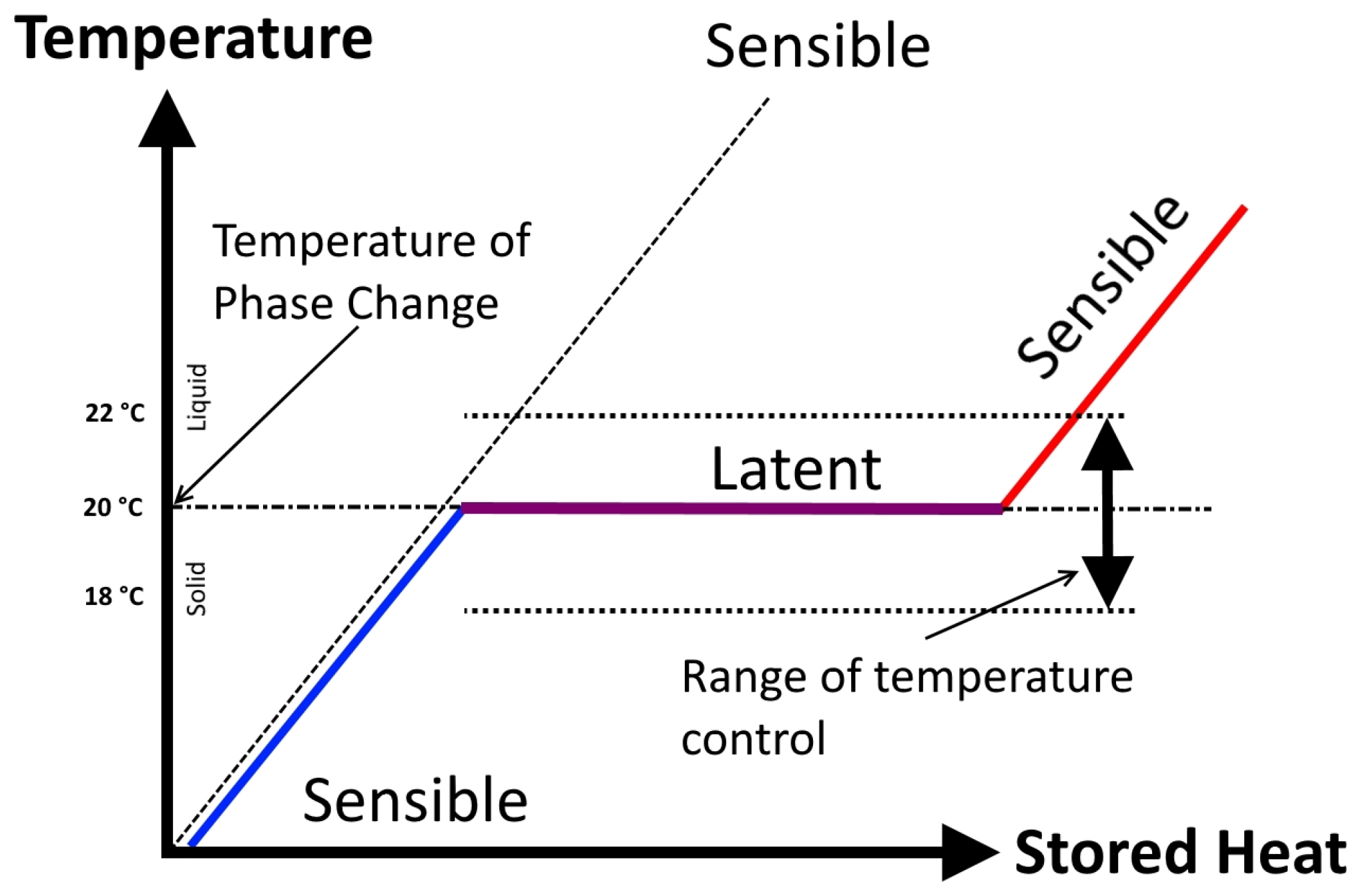
The principle of TES is based on an increase in temperature (sensible TES) or change of phase (latent TES). Starting with an initial solid state, heat addition to the substance first causes sensible heating of the solid, followed by a solid-to-liquid phase change, a sensible heating of the liquid, a liquid-to-vapor phase change and a sensible heating of the vapor [
4].
There are two forms of heat relevant in TES, sensible heat and latent heat. Sensible heat is defined as heat changing the temperature of the storage substance. The amount of stored heat that caused the temperature growth is commonly called the heat capacity of the storage medium. During the phase change process, changes of temperature of the material do not occur. This temperature is called the melting temperature. On the other hand, the heat supplied into the material is called latent heat. The quantity of latent heat is derived from the difference in enthalpy of the liquid and solid phase. Thermal energy storage realized by phase change materials (PCMs) exploits not only sensible, but especially latent heat [
5]. That is the reason that PCMs are capable of storing and releasing large amounts of energy. PCMs are either packaged in specialized containers, such as tubes, shallow panels and plastic bags, or contained in conventional building elements, such as wall boards and ceilings, or encapsulated as self-contained elements [
3].
The main parameter of the accumulation of sensible heat is the specific heat capacity. This parameter determines the amount of energy needed to change the temperature of 1 kg of the substance by 1 K. The amount of sensible heat energy can be calculated from Equation (
1).
where
| m | mass | (kg), |
| initial temperature | (K), |
| final temperature | (K), |
| specific heat capacity | (). |
Accumulation of latent heat exploits the specific heat capacity and the change of the accumulated medium, during the phase change process where the latent heat is released or absorbed. During the phase change, the temperature of the substance remains constant, and it is possible to store and release large amounts of energy. This is the reason why latent heat storage is one of the most efficient ways of storing thermal energy [
6]. However, there may be a slight change in volume. The amount of energy is determined by the enthalpy value during the phase change, in the solid state and in the liquid state, according to the following Equation (
2).
where
is the enthalpy change (J·
).
Figure 1 shows the principle of thermal energy storage in the form of latent and sensible heat in the PCMs.
There are three types of PCM: organic, inorganic and eutectic PCM. The most important property is high thermal energy storage capacity, and in general, inorganics have a higher one than organics, but there are some other subjects to take into account for choosing these materials [
8].
Organic PCMs are composed of paraffin, fatty acids or sugar alcohol. The principal advantages are their chemical and thermal stability. They are usually non-corrosive, recyclable and have little or no subcooling [
9]. Unfortunately, the disadvantages of using organic PCM are their flammability, low thermal conductivity and their phase change enthalpy being lower than other types of PCM [
8].
Inorganic PCMs include salt hydrates, salts and metals. They cover a wide range of phase change temperatures. Inorganic PCMs usually have higher enthalpy per volume due to their high density. However, they have the disadvantages of corrosion, subcooling, phase segregation, lack of thermal stability and phase separation [
9].
The eutectic PCMs are a combination of chemical compounds or elements that have a single chemical composition and that solidify at a lower temperature than any other composition obtained from the same components. The combinations can be organic-organic, inorganic-inorganic or inorganic-organic [
10].
In fact, all materials can be considered as PCMs. However, effective and predictable energy storage allows only some of them.
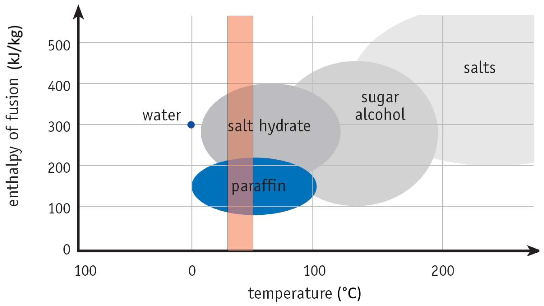
Figure 2 shows several materials suitable for thermal energy storage. For application in buildings, it is necessary to know the specific heat of fusion and the temperature at the time when the phase change occurs.
Figure 2 also illustrates the temperature band that represents a typical temperature comfort zone in households. As can be seen, in the temperature range from 15 °C to about 30 °C, the most commonly used are paraffin and salt hydrates [
11,
12]. This working range is positively reflected on heating and cooling energy demand. The main advantages of the PCMs are reducing of use of cooling systems and using the stored energy during the night.
PCM can be incorporated in construction materials using different methods, such as direct incorporation, immersion, encapsulation, microencapsulation and shape-stabilization [
13]. Traditionally, the application in the envelope of the room has been studied as one of the best options to incorporate PCM into buildings [
14] because such a solution offers a large area for passive heat transfer. Similarly, PCM can also be impregnated or mixed with concrete or mortar. Other approaches to incorporate PCM in building walls are still under investigation.
The passive approach in terms of efficiency mainly depends on the incorporation method and the current technical and technological development of materials. Other efficiency increasing is possible in an active approach when the PCMs is directly integrated into the energy system in the building, e.g., in ventilation systems, cooling ceilings, cooling beams, etc. These active systems affect the temperature of the air flow around the element from the PCM. The use of the air flow as forced convection to obtain energy from storage materials is very important, as is described in [
15]. For other applications, PCMs can serve as a reservoir of excess energy for future use. Some new applications are being steadily developed and tested; noteworthy are [
16,
17,
18,
19,
20,
21,
22]. One of the possible ways of integrating PCMs into the energy systems is presented in this paper.
1.2. The Application of Peltier Coolers in the Cooling System
Thermoelectric coolers, also known as Peltier coolers, are solid-state heat pumps. The principle of thermoelectric cooling dates back to the discovery of the Peltier effect by Jean Peltier in 1834.
Thermoelectric coolers (TEC) are based on the Peltier effect to convert electrical energy into a temperature gradient [
23]. TECs are composed of a number of n-type and p-type semiconductor junctions connected electrically in series by metallic interconnects and thermally in parallel, forming a single-stage cooler [
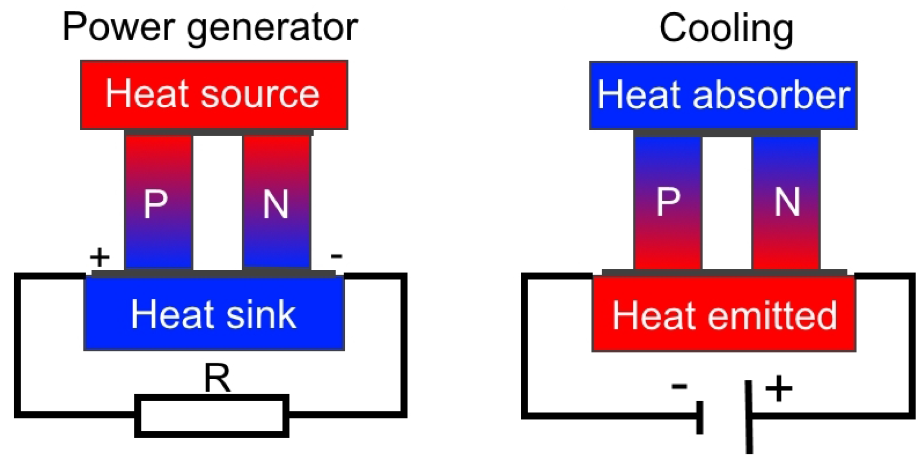
24]. When a DC power source is applied, semiconductors transfer heat from one side of the TEC to the other side, so that one surface of the TEC is cooled, and the opposite surface is heated.
On the right in
Figure 3 is shown a thermoelectric cooler where the electrical current flows from the n-type element to the p-type element [
25]. The temperature of the cold junction decreases. This happens when the electrons pass from a low energy level element (p-type) to a high energy level element (n-type) through the cold junction. At the same time, the electrons carry the absorbed heat to the hot junction. This heat is transferred to the heat sink, whilst the electrons return to a lower energy level in the P-type semiconductor (the Peltier effect) [
24].
The Peltier effect is a reverse of the Seebeck effect. If there is a temperature difference between the cold junction and hot junction of n-type and p-type thermoelements, a voltage (called Seebeck voltage) directly proportional to the temperature difference is generated [
24]. The Seebeck effect is shown in
Figure 3 (on the left).
The quality of the TECs depends on many parameters, such as the electric current, the temperature gradient, the thermal and electrical conductivities of the thermoelement and the thermal resistance of the heat sink on the hot side of the thermoelectric cooler [
26]. The number of thermoelements in a thermoelectric module mainly depends on the required cooling capacity and the maximum electric current.
Some of the recent studies are focused on TECs and thermoelectric generators (TEGs) define in combination with solar energy and PCMs [
27,
28,
29,
30]. The application areas for TEC and TEG are both in specific fields. TEG is an alternative choice to convert solar energy into electricity from photovoltaic (PV) technology [
28]. New areas of research of thermoelectric technology are automotive, cooling of electric devices and buildings, etc.
Some of the application of TEC can be a new thermal control technology, which integrates TE modules and PV units within the building envelope [
29]. It can actively control heat flux in the wall and compensate passive heat losses or gains by using solar energy. The studies about TEC [
30], a thermoelectric space cooling system integrated with PCM thermal storage, discovered that the experimental tests have demonstrated that the average COP increased by 56% for the lab-scale thermoelectric cooling system due to integration with PCM.
However, the mentioned technologies are not used in buildings; so far, only theoretical research and experiments of these systems have been made. More work should be done for their application in buildings. The development of new thermoelectric materials with better parameters and lower prices can make a big breakthrough for the new application areas.
2. Methods
The proposed technology is based on the PCM panels DuPont (Wilmington, USA, Delaware) Energain grouped into one active element that is described in the following text. The technology also includes other technical devices, such as energy meters, valves, sensors and regulators. The technology is regulated, monitored and controlled by the LonWorks bus system (LON). The difference between standard solutions and the proposed technology is the ability to use energy from any available energy sources, including renewable energy sources, e.g., PVs, solar thermal collectors or heat pumps. Another difference is the active electric cooling that is not common in the PCM devices.
The paraffin-based PCM Energain from DuPont was used in the experiment. This thermal mass panel is covered by aluminum protective foil. The core material is a mix of a copolymer and a paraffin wax PCM, which provides the panel’s functionality. The PCM Energain uses molecular encapsulation developed by DuPont, which allows a very high concentration of PCM within a polymer compound. The polymer molecules are designed to create a homogenous compound. Molecular encapsulation forms a highly durable PCM material with a wide operating temperature range from 0 to 40 °C and allows drilling and cutting through the material without any PCM leakage [
31]. At temperatures below 18 °C, the wax remains in a solidified state. Once the temperature inside a room reaches 22 °C, the phase change takes place, and the paraffin wax melts [
32].
2.1. Accumulation Device
Measurement of the parameters was done on the active technology for heating and cooling with the accumulation of heat or cold, which is located in a laboratory at the Faculty of Applied Informatics of Tomas Bata University in Zlín in the Czech Republic. This system is composed of two thermal accumulation panels. The dimensions of one panel are 1.25 m × 0.083 m × 2.07 m, and each of them is composed of 6 layers of PCM DuPont Energain panels. The rear part of the thermal panels is insulated. There is a water tube heat exchanger for heating and cooling between layers of the PCM panels. The heat exchanger is connected to the water tanks with cold or hot water. Three electric heating foils are also imposed inside the accumulation panels. As previously mentioned, the proposed technology is able to use any common energy sources, including renewable energy sources, for example heat pumps, solar thermal collectors or PV systems, in combination with electric thermocouples. The mass of the thermal panels is composed of a mixture of polyethylene and paraffin wax. The paraffin wax is in the solid state at temperatures below 18 °C. When the temperature of the panels rises above 18 °C, the wax begins to melt and absorbs up to 515 kJ·
of heat between 18 and 24 °C. Its melting point is about 22 °C, which corresponds to standard indoor temperature conditions [
32].
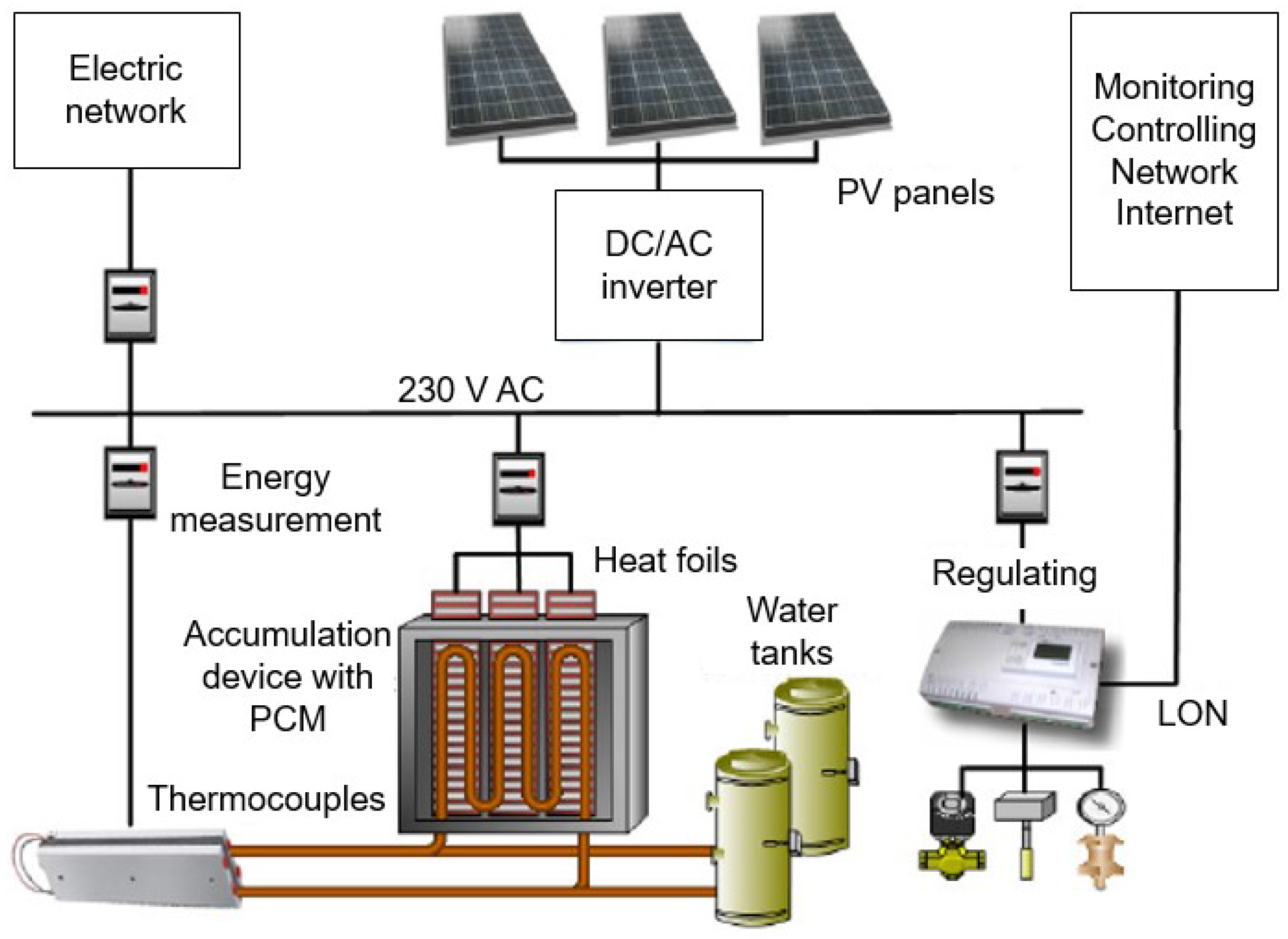
Figure 4 shows the whole technology and its connection with the PV system, monitoring and controlling system, the Internet and the electric network.
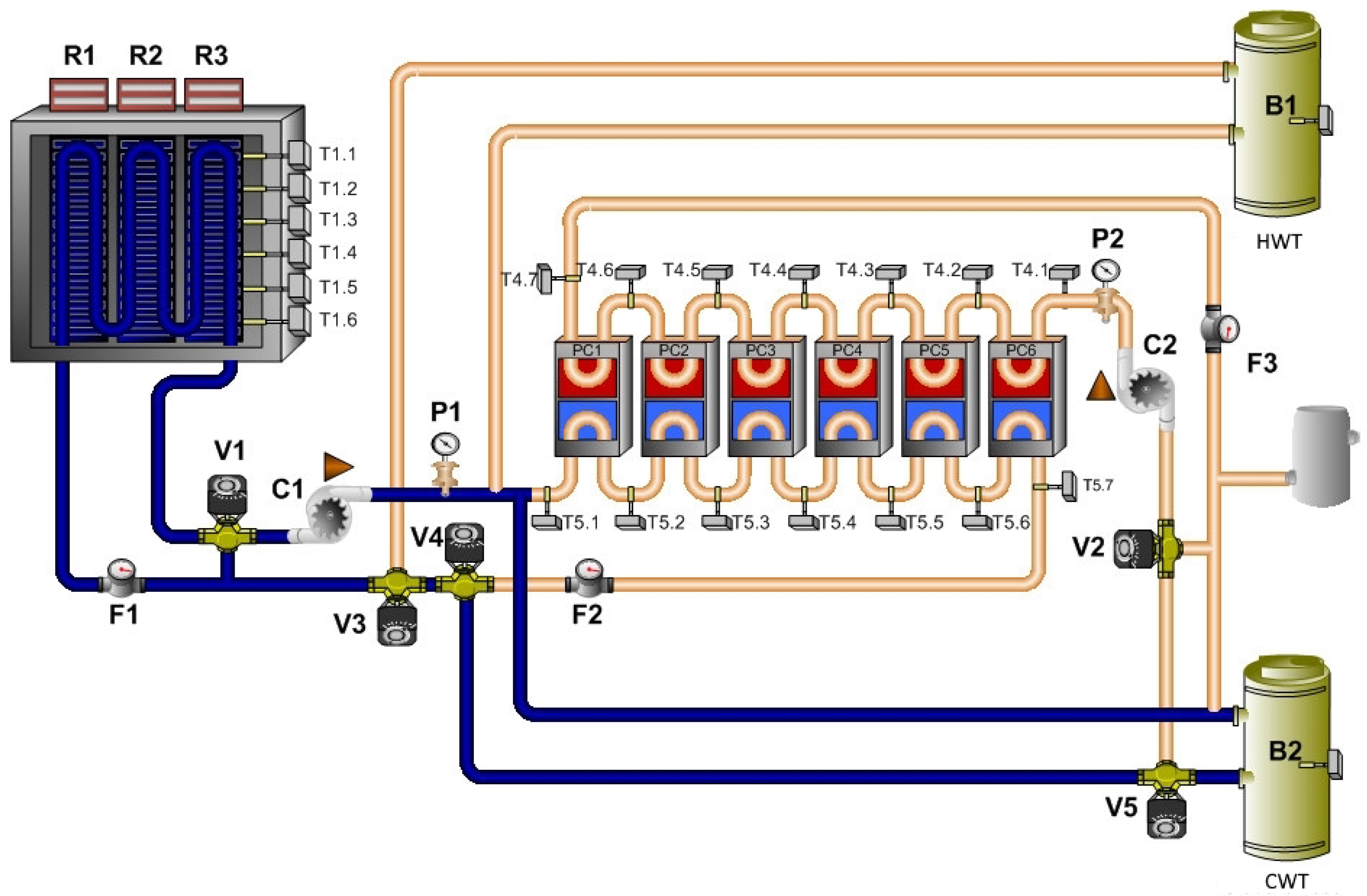
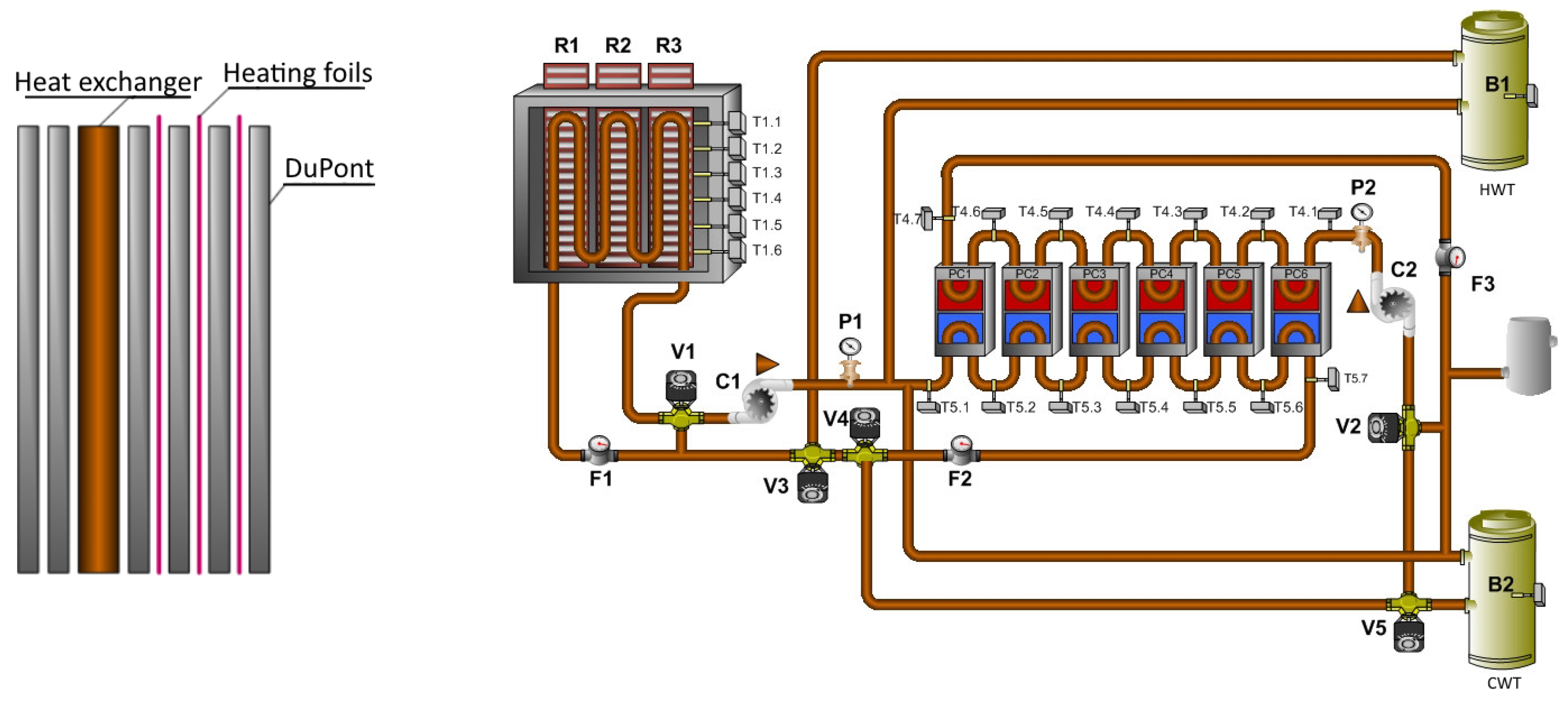
Figure 5 shows the hydraulic connection of the technology. The technology can use many different heat sources. The technology is powered by a 230 V AC power grid. It can also be powered by the PV system. Heating of the hot water tank is done by the solar thermal collectors or by the air-to-water heat pump. The heat pump can also be used for cooling of the cold water tank.
2.2. Photovoltaic System in Combination with the Thermoelectric Coolers
The technology also includes a thermoelectric cooler powered by the PV panels or from the power grid. The principle is when one side is getting hot, the opposite side is getting cold. The coolers are equipped with heat exchangers for removal of heat or cold.
To determine the number of thermocouples, it was necessary to calculate the cooling capacity of the thermal panel. Consider that the thermal panel has a temperature of 27 °C before the start of cooling. The panel must be cooled down to 16 °C during the day. The energy that needs to be removed from the thermal panels is determined by Equation (
1). The average specific heat capacity of the thermal panel is about 11
(16 to 27 °C), and its weight is about 129 kg.
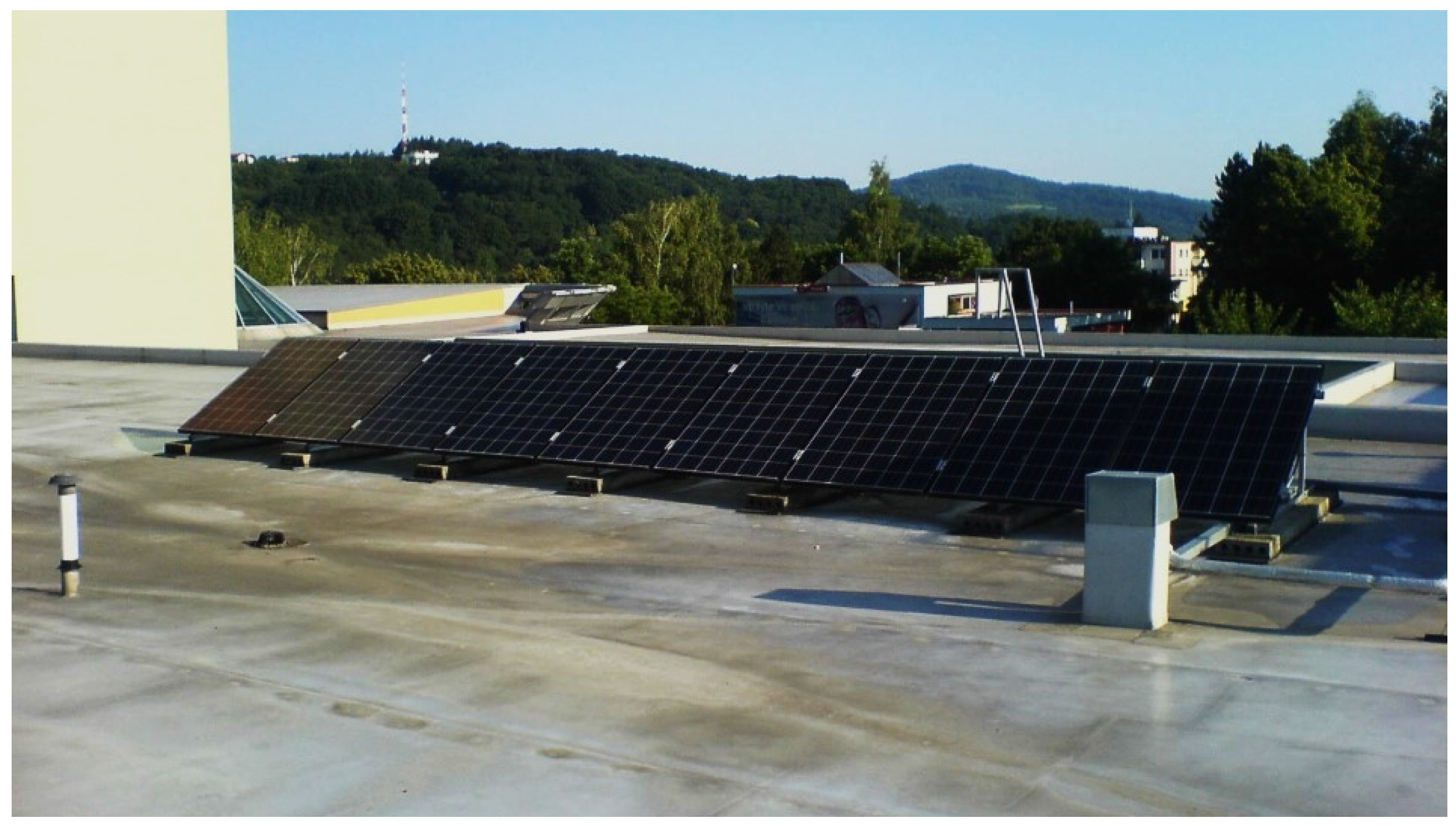
When the charging of the thermal panels takes 8 h, the overall performance of the thermocouples must be about 0.55 kW. For the thermocouples with an efficiency of 50%, the input power for the thermocouples is required to be about 1100 W. The thermoelectric cooler is composed of six thermoelectric modules. One thermoelectric module has a maximum input power of 200 W. In the summer months, solar radiation falling on PV panels has an average intensity of 750 . During the design of the technology, a PV panel with an efficiency of 15% and an inverter with an efficiency of 92% were expected. With these values, the power output was expected to be around 103.5 . To ensure power supply, an area of the panels of about 11.5 is required . One PV panel has dimensions of 1.25 m × 1 m. The installed PV system consists of 9 polycrystalline PV panels with a total area of 11.25 .
Other important information was the assessment of the real energy efficiency of the used PV system. The producer of these panels declares an energy efficiency of 15%. The output of the PV panels is converted from DC to AC 230 V by the inverter. The inverter Sunny Boy has an efficiency of 91.8%. The rest of the converted energy is lost in the form of heat.
The energy efficiency of the PV system is calculated according to Equation (
4):
where
| performance of a PV panel | (W), |
| power of solar radiation | (W), |
| E | intensity of solar radiation | (), |
| surface of the PV panels | (). |
The intensity of solar radiation was measured by a solarimeter. The real production of the PV panels was determined by the software of the PV inverter. The real energy efficiency of the installed PV system was set at 10.5%. The value was measured in our other research focused on the verification of the effectiveness of PV panels and their economic return [
33,
34]. The installed PV panels are shown in
Figure 6.
2.3. Operation of the Technology
The technology for the accumulation of the thermal energy can work in many different modes, which depend on the requirements. The technology can be used as a standard passive system. In this mode, the technology accumulates the heat or cold. This mode can reduce the temperature peaks and keep a stable temperature in the monitored room during the day and night. The technology can also work in active mode. In this mode, the technology is able to influence the room temperature by accumulating the heat or cold obtained from the external sources. Individual operating modes are described in the following paragraphs of the text.
2.3.1. Heating of Thermal Panels by Electric Heating Foils
The electric heating foils are placed inside the panel. The foils are divided into three sections. The performance of each foil is 600 W. Switching of individual sections depends on the temperature of the panel or the production of the PVs [
35].
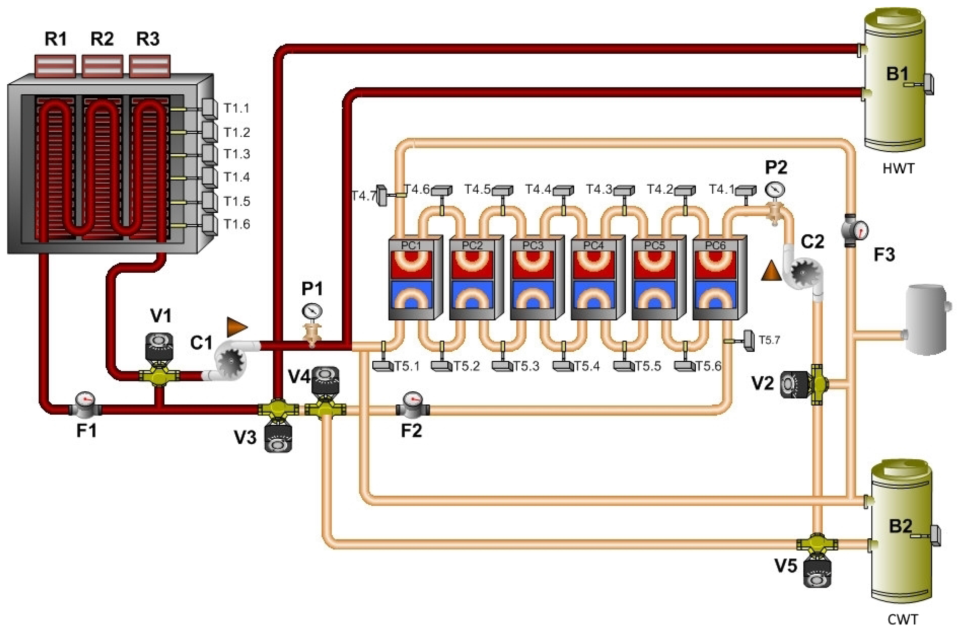
2.3.2. Heating of Thermal Panels from the Hot Water Tank
The tube heat exchanger to transfer heat from the hydraulic part of the technology is placed inside the thermal panels. The hot water tank can be heated by any installed technology that is available. It is possible to use a heat pump, solar thermal collectors or an electric boiler in this case. This mode of the technology is shown in
Figure 7.
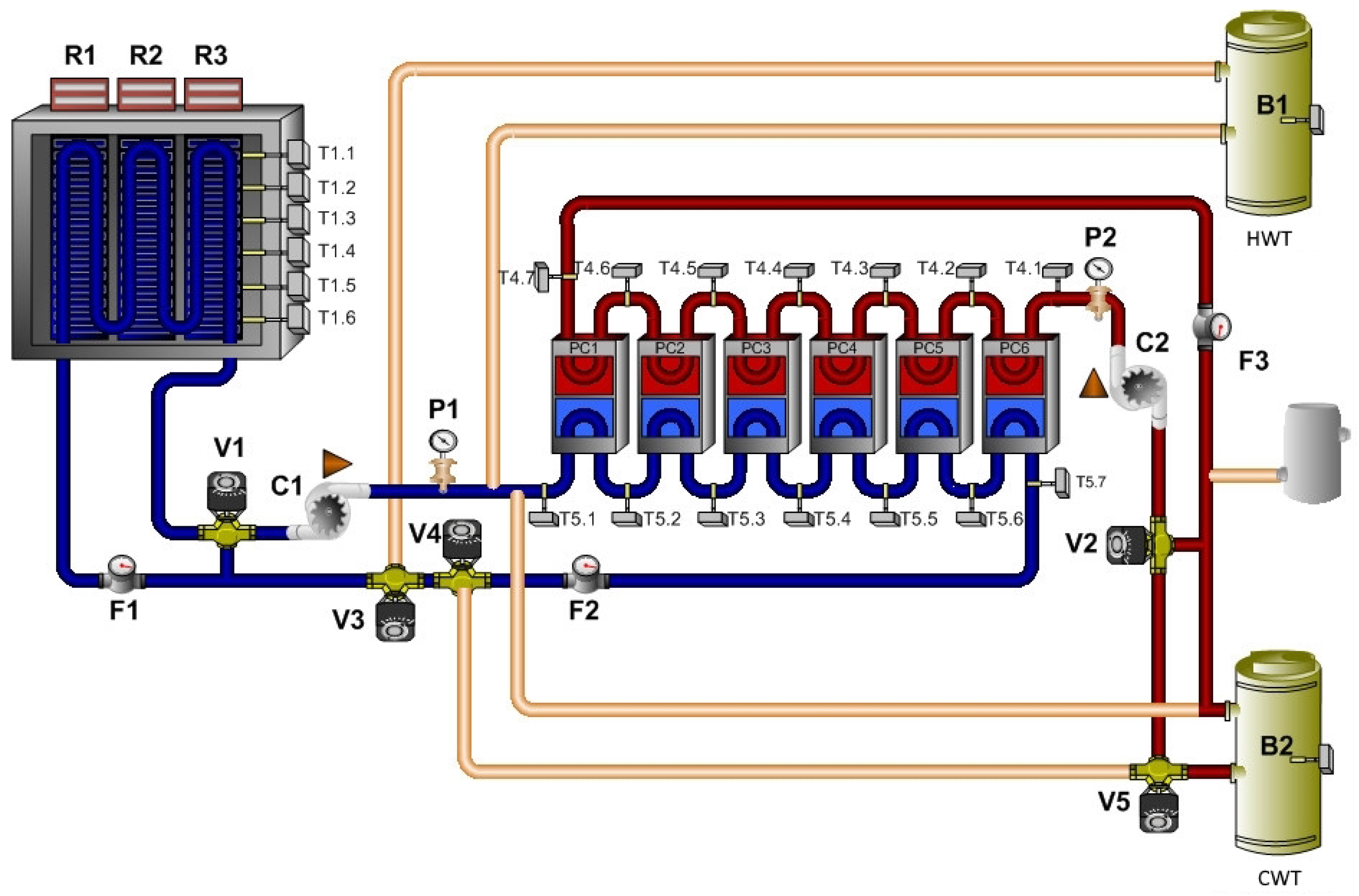
2.3.3. Cooling of Thermal Panels from the Cold Water Tank
The principle of this mode is similar to the previous mode, and it also uses the heat exchanger. It is possible to use the cooling mode of the heat pump. This mode of the technology is shown in
Figure 8.
2.3.4. Cooling of Thermal Panels by Thermoelectric Coolers
The cooling mode uses the thermocouples, which are able to reach a low temperature for the water. However, it is necessary to ensure the cooling of their hot side, because this side produces a large amount of waste heat. The installed system uses a hydraulic circuit for removing the cold from the thermoelectric elements into the thermal panels and a second circuit for waste heat dissipation. The number of switched on elements depends on the amount of supplied energy from the PVs [
35]. This mode of the technology is shown in
Figure 9.
2.3.5. Removing of Heat or Cold from the Thermal Panels
The technology can also be used without active cooling or heating. In this mode, it is possible to drain away the stored energy from the panels into the hot or cold water tank.
2.4. Measurement
The aim of the measurement was to determine the changing of the ambient temperature during the heating mode and cooling. The different parameters of the system were measured, but the most important were the inside temperature, the surface temperature and the heat flux of the panel, as well as the temperature at the inlet and outlet of the heat exchanger. Furthermore, the inside air temperature and the outside air temperature were measured by the specific weather station.
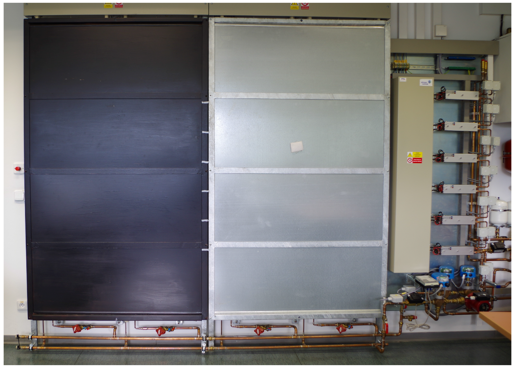
As you can see in
Figure 10, the surface of one panel was painted with black matte paint. This change caused a growth of the emissivity of the surface and, thus, also the heat transfer coefficient. The emissivity was measured by the thermal imager and also the pyrometer. Previous research has established the average heat transfer coefficient to be a value of 4.1
for the unmodified surface and 8.3
for the panel with a modified surface. The heat transfer coefficient was determined by a calculation involving natural convection and radiation; below are Equations (5)–(7).
where
| Nusselt number | (-), |
| specific heat capacity | (), |
| temperature difference | (°C), |
| g | gravitational acceleration | (), |
| β | thermal expansion | (), |
| l | characteristic dimension | (m), |
| η | dynamic viscosity | (Pa·s), |
| ν | kinematic viscosity | (), |
| λ | coefficient of thermal conductivity | (), |
| convective heat transfer coefficient | (). |
where
| radiative heat transfer coefficient | (), |
| ε | emissivity | (-), |
| the difference of radiation angles between | |
| the two object. In this case, | (-), |
| σ | Stefan-Boltzmann constant | (), |
| g | gravitational acceleration | (), |
| T | thermodynamic temperature | (K). |
where
h is the total value of the heat transfer coefficient (
).
The dynamical parameters of the PCM panel can be described by the time constant, which could express the course of the temperature growth or drop; it can be described as energy release in time. The time constant was determined by several methods from measuring the cooling process and calculation. Calculations were carried out according to the following Equations (8)–(10) [
36].
where
| θ | initial temperature | (°C), |
| temperature reached | (°C), |
| temperature stabilization | (°C), |
| Biot number | (-), |
| Fourier number | (-). |
where
| h | heat transfer coefficient | (), |
| l | characteristic dimension | (m), |
| λ | coefficient of thermal conductivity | (), |
| a | thermal conductivity | (), |
| τ | time constant | (s). |
where
| ρ | density | (kg·), |
| V | volume | (), |
| A | area | (). |
The time constant is about 6.8 h for the unmodified surface and about 5.5 h for the modified surface. The results of the measurement and calculation of these parameters are described in [
37].
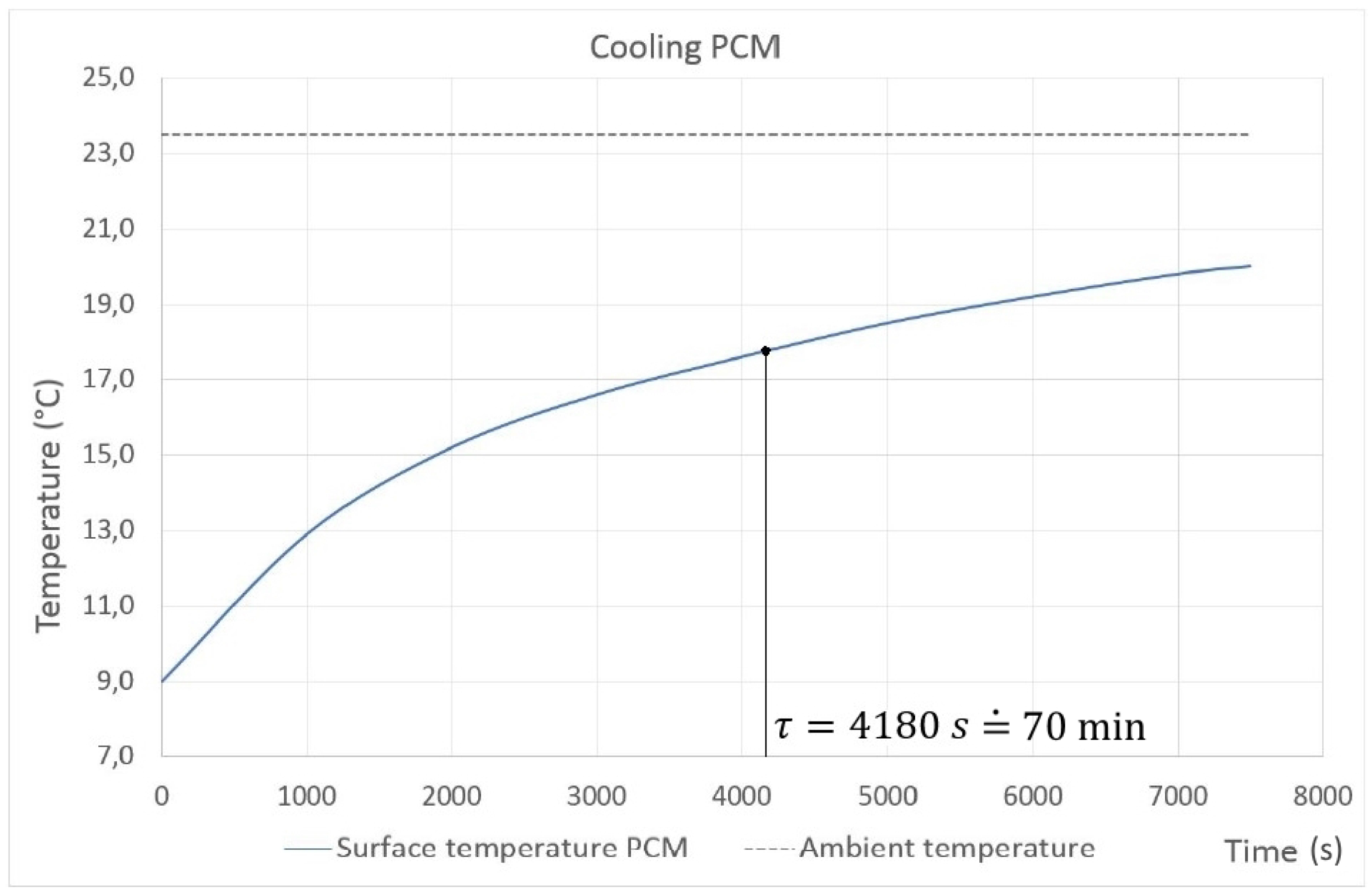
The measurement of the thermal time constant of the PCM sample was performed in the temperature range from 9 to 24 °C, where the thermal heat capacity of the PCM sample was established. The dimensions of the test sample were 0.5 m × 0.5 m and a thickness of 5 mm. The aim of the measurement was to specify the time constant in the cooling cycle. The sample was cooled to 9 °C in a cooling chamber, and then, it was placed in a room with an ambient temperature of 23.5 °C. The thermal time constant can be determined by the following Equation (
11).
where
| temperature in time t | (°C), |
| initial temperature | (°C), |
| ambient temperature | (°C), |
| t | elapsed time | (s), |
| τ | time constant | (s). |
The measured parameters of the PCM panel were the heat transfer coefficient, the time constant and the specific heat capacity. The next parameters measured were the mass flow and the water inlet/outlet temperatures. From all of these parameters, it was possible to determine the amount of heat that was delivered into or removed from the thermal panels by the heat exchanger. The amount of heat can be calculated from Equation (
1) and the power from the following Equation (
12).
where
is mass flow (kg·
).
3. Results and Discussion
The measurement of the heating of PCMs has already been examined many times. Thus, the main objective of the measured results presented in the following was to examine some possibilities of using PCMs for cooling and consequently proposing some improvements. In other words, its intention was to find out how the PCM behaves in the temperature range that is specific for cooling. For this purpose, the specific heat capacity is a very important parameter. The used PCM has this value around 6800 in the temperature range from 10 to 21 °C. The main limiting factor of cooling devices is the risk of the condensation of water vapor. Therefore, it must be ensured that the surface temperature is at least 1 K above the dew point temperature.
First of all, it was necessary to determine the thermal time constant of the piece of the PCM plate. The measurement has been made as simple as possible, focusing on the temperature changes; see
Figure 11. As described in Equation (
11), the thermal time constant is the time taken for attaining 63% of the ambient temperature for the test sample. As can be seen, the time constant is almost 70 min. The value is quite high for such a small test sample because of its high specific heat capacity. The chart shows the behavior of the material, especially in terms of the time that is required to reach room temperature. This material represents a nonstandard possibility of being used in cooling systems, mainly due to its good parameters.
Three different measurements on the proposed technology have been made there. The first measurement represents the use of active heating mode (
Figure 7). The second measurement represents the standard passive mode (
Figure 8). The last measurement represents the active cooling mode (
Figure 9). It is good to mention here that the heating and cooling of water in water tanks were done by the solar thermal collectors and the heat pump.
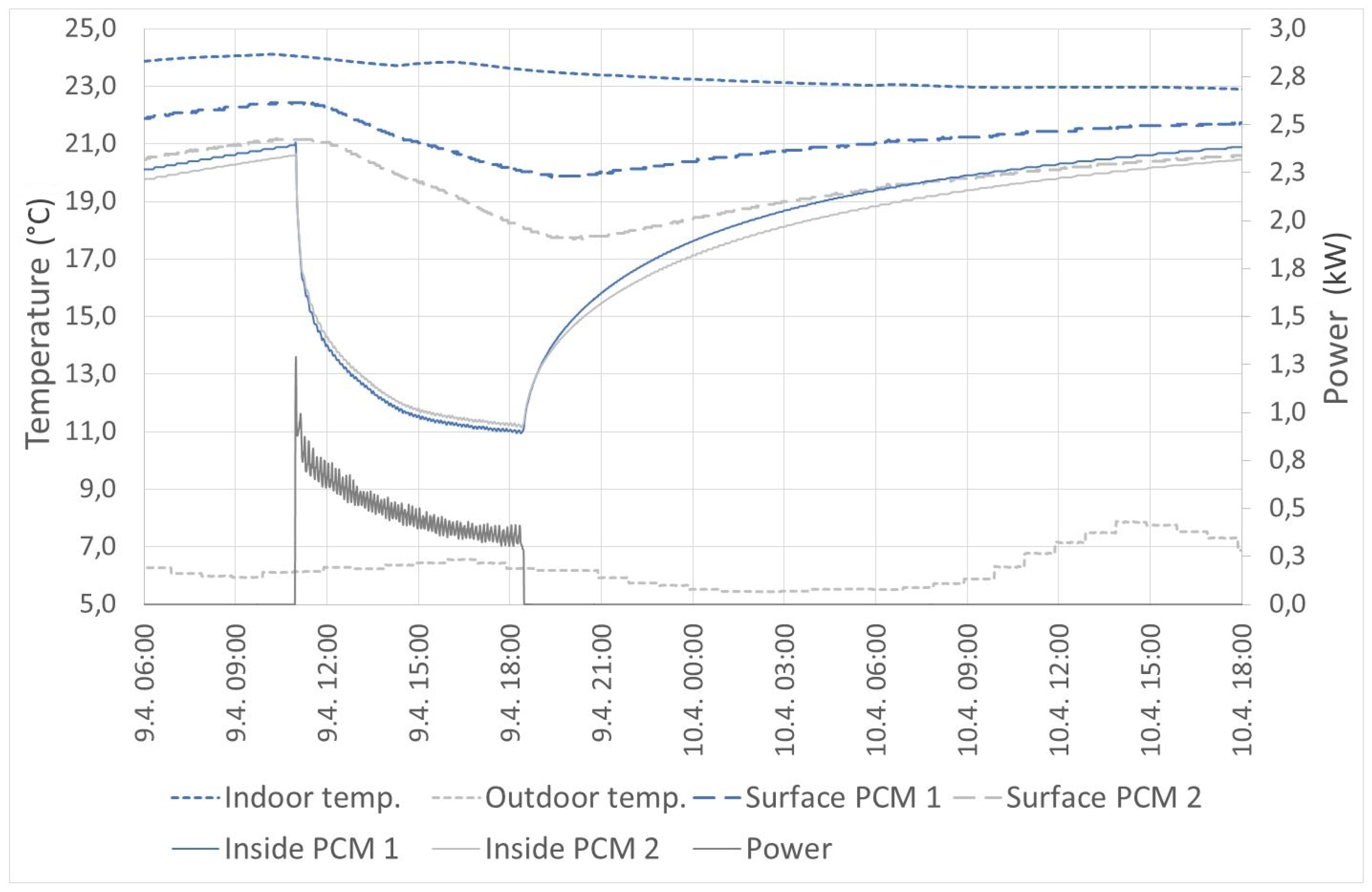
The active heating mode in
Figure 12 shows the progress of the heating of the thermal panels. The outdoor temperature ranged from 7 to 20 °C. At the beginning, it is possible to see that the surface temperature increased slightly, but then, the temperature began to rise dramatically. This effect occurred when the material ceased to accumulate latent heat and started to accumulate only sensible heat. The thermal panels were able to increase the temperature of the air in the room during the day and keep it stable during the following night. Energy supplied to the panels was 1.9 kWh. This energy was made by the heat pump, because the outdoor ambient temperature was too low for using the solar thermal collectors.
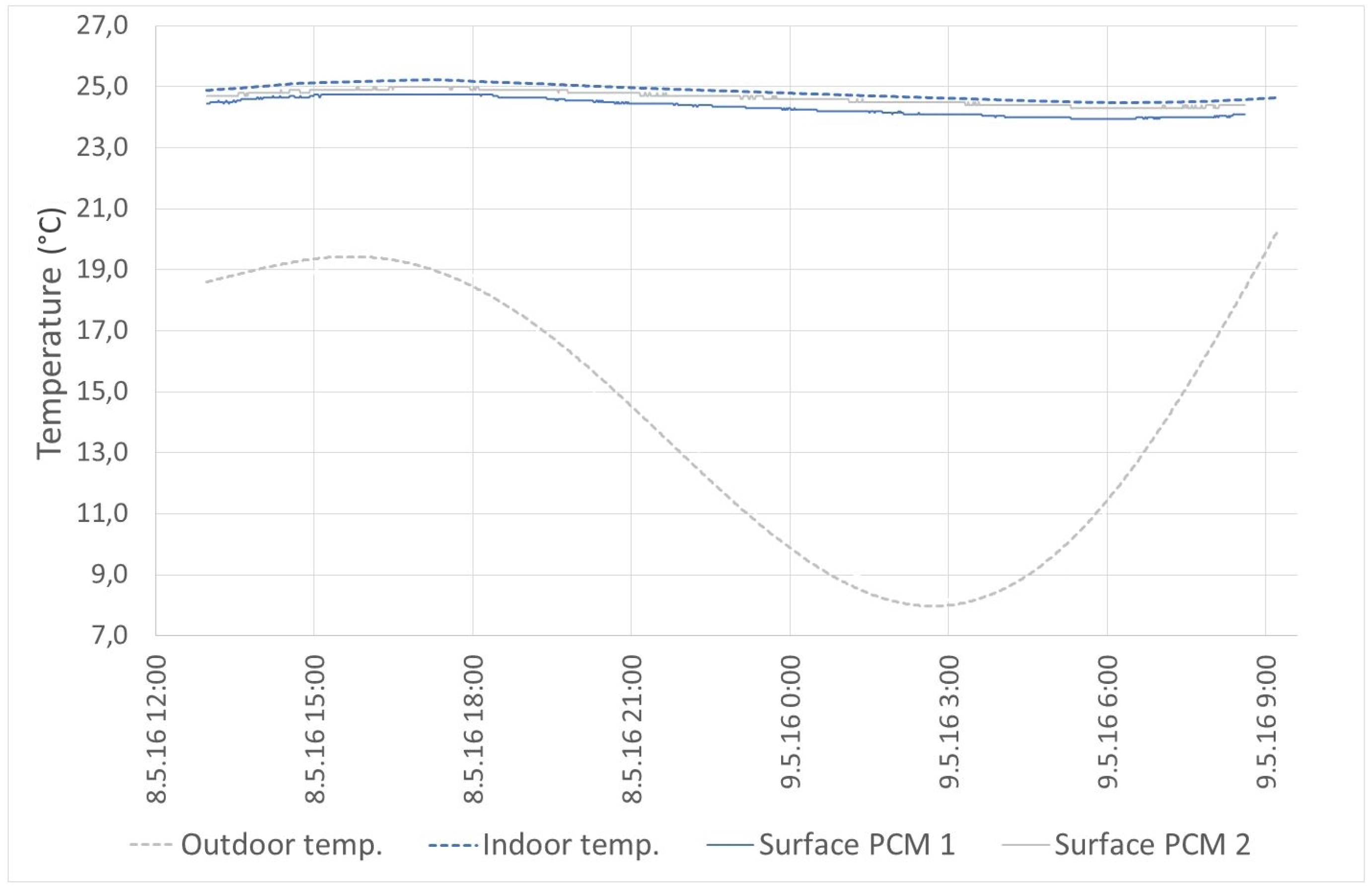
In passive mode, PCMs are used especially to reduce the temperature fluctuation and also to stabilize the indoor air temperature. An example of this behavior can be seen in
Figure 13. This mode ensured stabilization of the indoor air temperature at 25 °C when the outdoor temperature oscillated from 8 to 20 °C.
On the other hand, the active mode allows one to use PCM panels as a reservoir of excess energy.
Figure 14 shows an example where the PCM panel was used as a cold reservoir. It is possible to see the effect of surface modification. The modified surface with higher emissivity has a higher heat flux, which caused its higher surface temperature. In practice, it is appropriate to ensure the highest possible emissivity value. The time of change of the surface temperatures from 21.2 to 17.7 °C (unmodified surface) and from 22.4 to 19.8 °C (modified surface) was around 9 h. During this cooling, the total amount of energy drained from thermal panels was 3.7 kWh. The heating time was approximately 24 h.
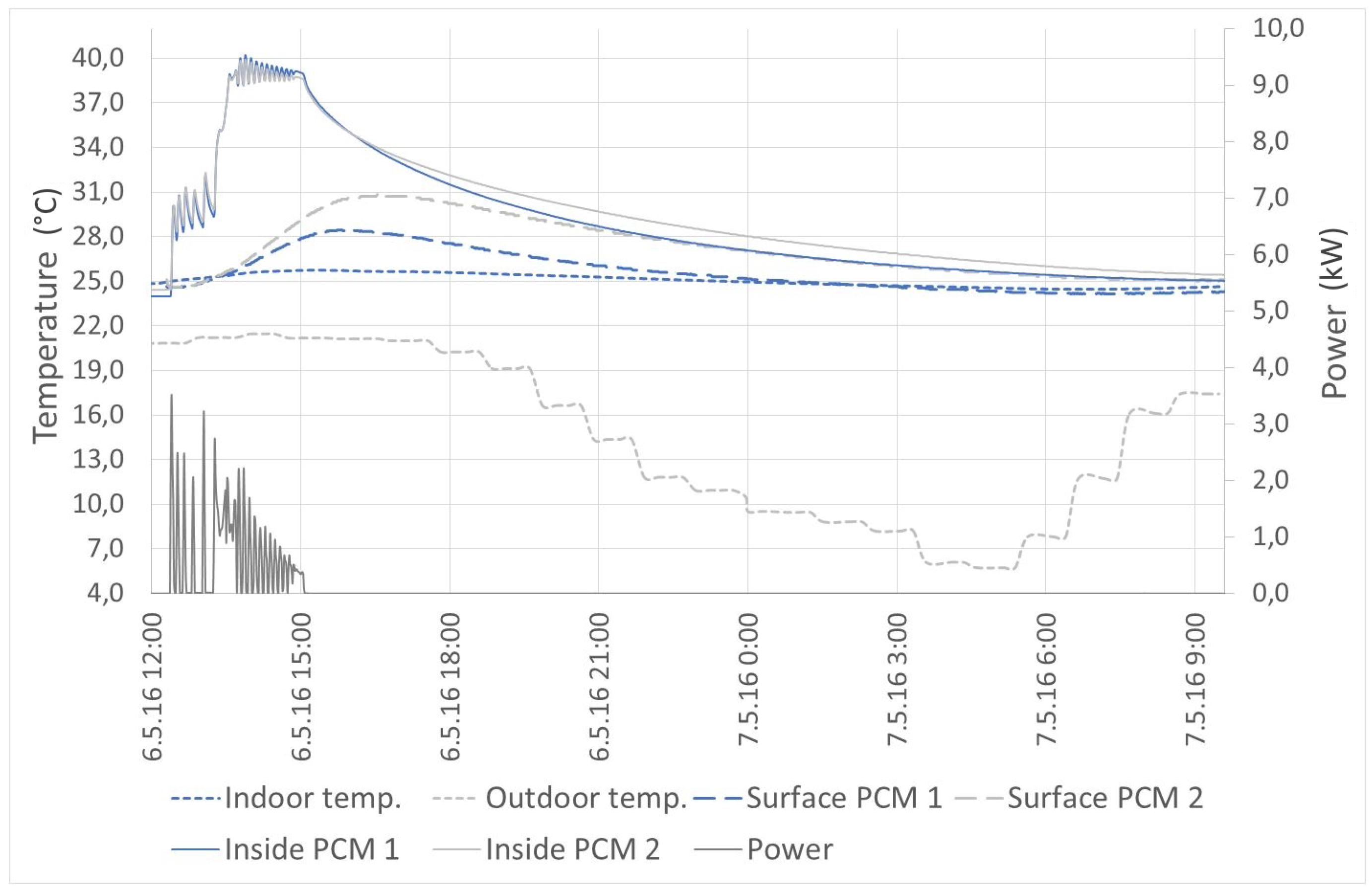
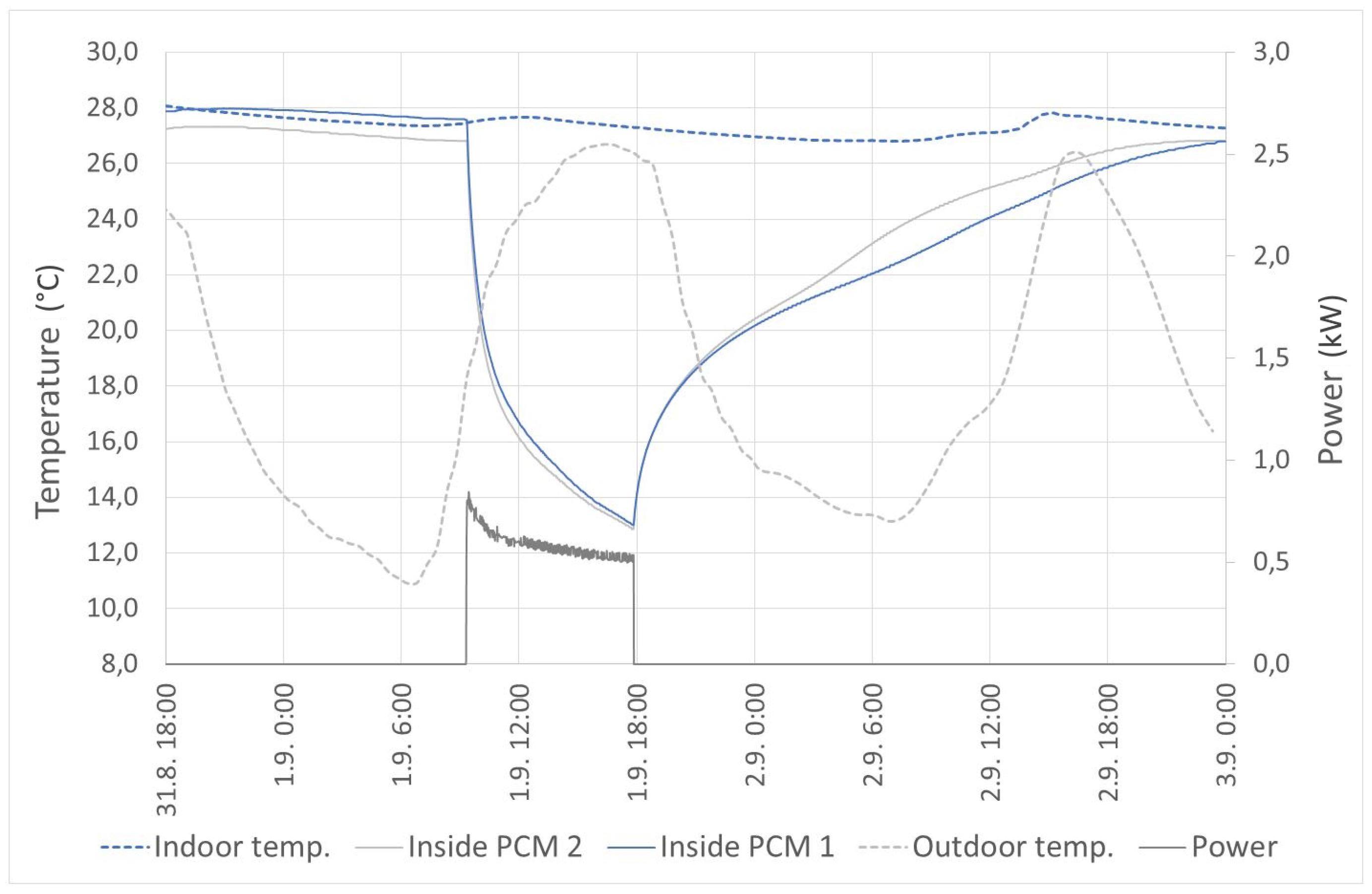
The last measured mode is active cooling by integrated thermoelectric coolers. The measurement was done during many hot summer days when the outdoor temperature reached up to 27 °C. In this mode, the thermal panels were able to reduce the indoor temperature from 27.8 to 26.5 °C. The measured parameters are shown in
Figure 15.
In
Figure 15, it is possible to see the slight decrease of the temperature in accordance with the outdoor temperature during the first 15 h. The active cooling was turned on in the next day at nine o’clock. When the outdoor temperature was increasing, the indoor temperature was increasing slightly, as well, and reached the top at 12 o’clock. The outdoor temperature was still increasing the next few hours. However, the thermal panels had been already cooled, so the indoor temperature began to decrease. The cooling was turned off at 18 o’clock, and the temperatures were still measured. The indoor temperature was steadily decreasing the next 12 h. After that, the indoor temperature was increasing again because the temperature of the thermal panel was above the phase change temperature range. It is possible to judge that the area of the thermal panels is low in comparison with the total area of the room. However, it can be resolved by higher heat flux, which can be improved, for example, by forced convection.
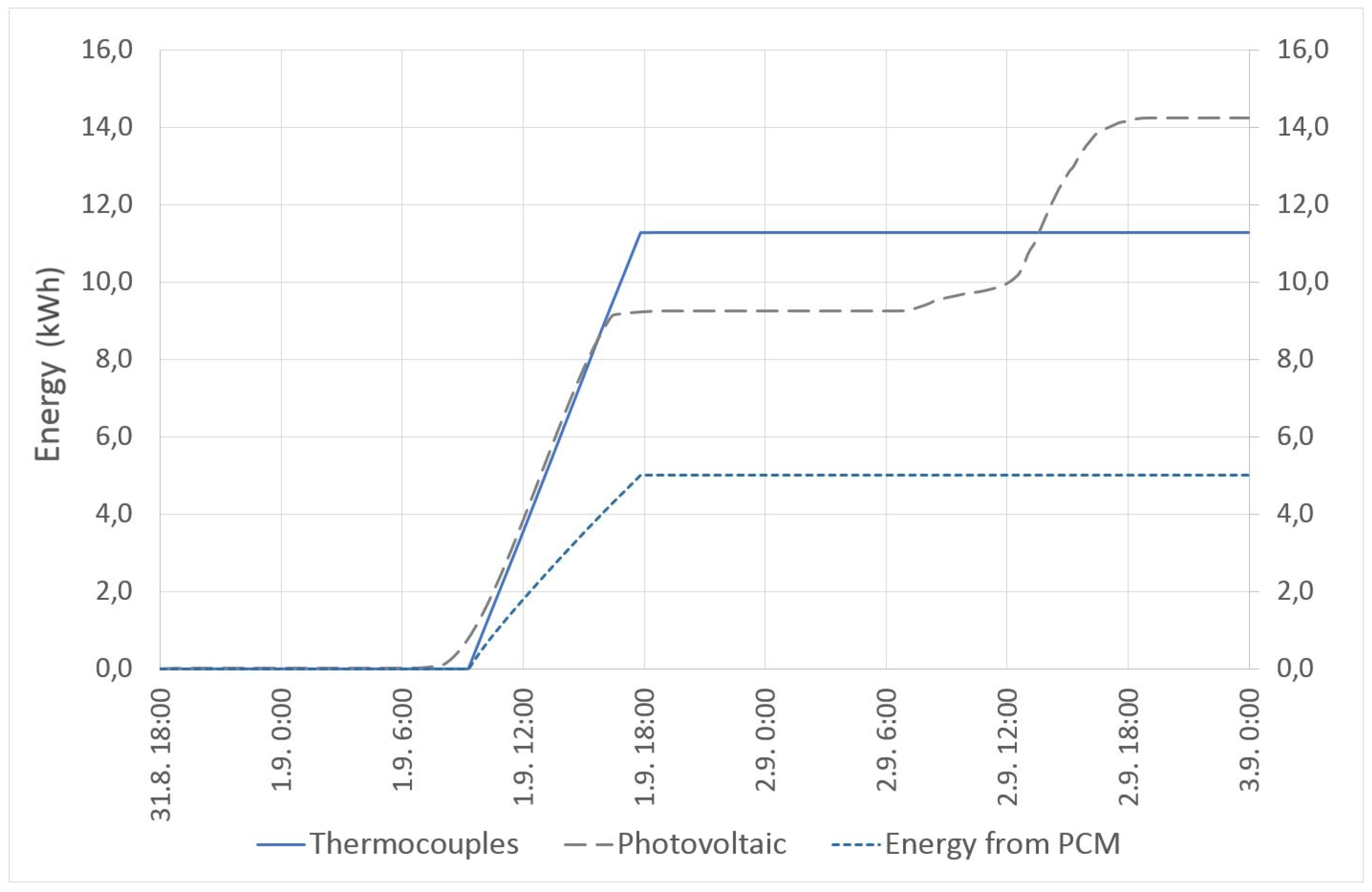
The thermoelectric coolers were powered by the energy produced by the installed PV system. The PV system produced over 14 kWh during the active cooling mode. The heat energy removed from the thermal panels was about 5 kWh. The thermoelectric coolers consumed over 11 kWh. The measured values show about 50% efficiency of the thermocouples (this was expecting during the designing of the technology). The energy consumption of the thermoelectric coolers and energy production from renewable energy sources are shown in
Figure 16.
The disadvantage of the thermoelectric cooling is producing much waste heat on the opposite side of the thermocouples. The hot side of TEC is cooling by a liquid cooler connected to the cold water tank. There is an opportunity to save some energy: use the waste heat for preheating hot water to save energy.
Table 1 shows measured and calculated energies that were produced by the PV system or thermal solar collectors and energy consumed by cooling or heating. The installed heat pump, Mitsubishi Zubadan, has an average COP (coefficient of performance) over 3.5 and an EER (energy efficiency rating) over 2.7. The table shows energies gained or removed from the thermal panels (PCM), energy gained from the PV system, energy consumed by the heat pump (HP) and thermoelectric coolers (TEC), and the last one is the balance of these energies (SUM). All of these examples have a positive energy balance. However, the performance and efficiency is dependent not only on the weather condition, but especially on the application of the energy source in the proper temperature range. The active and passive heating modes were measured when the outdoor temperature ranged from 7 to 20 °C. The active thermoelectric cooling was measured when the outdoor temperature ranged from 13 to 27 °C.
The opportunity for the implementation of the PCM in the thermal device that could have improved the utilization of renewable energy was presented in this work. The storage material was tested in the laboratory of environmental energy. As a heat or cold source, several sources of energy were used as described. All of these cases show a different efficiency and effect of the indoor environmental quality. The used PCM material has advantages in the case of the stabilization of the air temperature in the room.
In the case of the standard solution without PCM (radiators or/and air-conditioner), the thermal mass of the room is low. Therefore, the indoor temperature can rise and drop dramatically during the day and night. In this case, the indoor temperature must be regulated by active heating and cooling.
The experiment was done during a typical spring in the Czech Republic. The high outdoor temperature in combination with high solar radiation can cause overheating of the room during the day, but there can also be a problem with the low temperature at night. Moreover, most of the buildings have the heating system already turned off, and the cooling system is not turned on yet. The proposed technology is able to deal with this by passive or active mode. Therefore, the measurements were done when it was difficult to maintain the thermal comfort inside the building.


